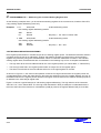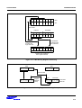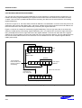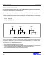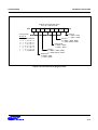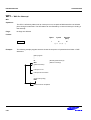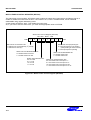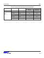
1
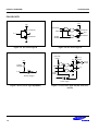
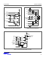
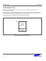
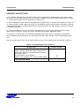
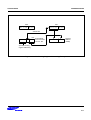
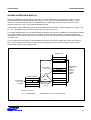
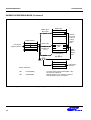
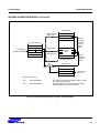
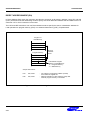
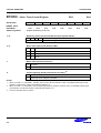
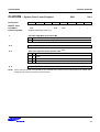
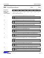
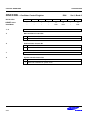
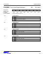
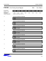
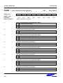
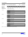
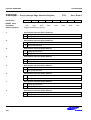
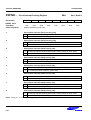
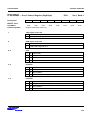
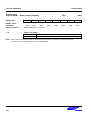
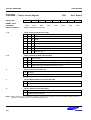
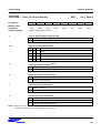
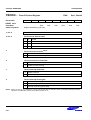
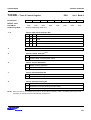
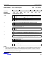
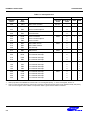
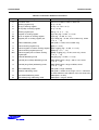
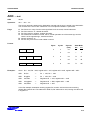
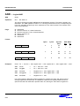
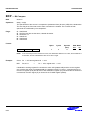
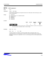
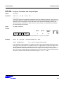
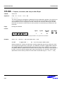
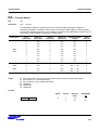
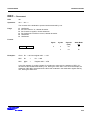
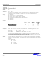
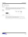
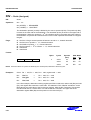
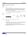
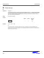
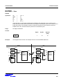
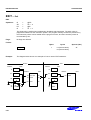
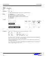
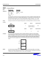
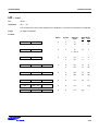
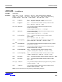
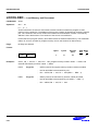
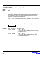
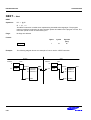
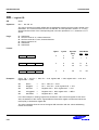
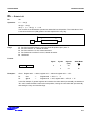
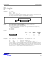
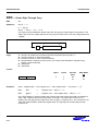
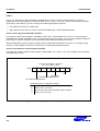
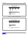
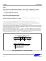
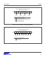
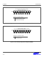
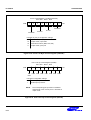
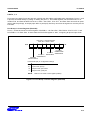
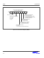
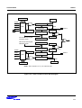
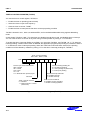
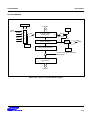
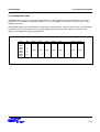
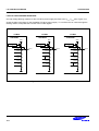
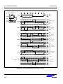
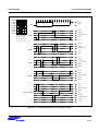
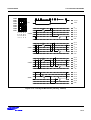
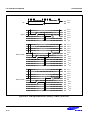
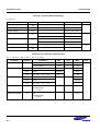
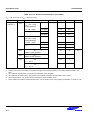
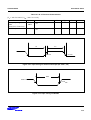
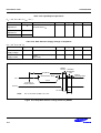
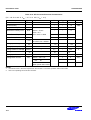
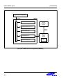
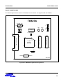
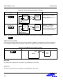
DEVELOPMENT TOOLS
S3C825A/P825A
Table 22-1. Power Selection Settings for TB825A
"To User_VCC" Settings
Operating Mode
Comments
The SMDS2/SMDS2+
supplies VCC to the target
board (evaluation chip) and
the target system.
To User_VCC
Off
TB825A
On
Target
System
VCC
VSS
VCC
SMDS2/SMDS2+
To User_VCC
Off
TB825A
On
External
VCC
The SMDS2/SMDS2+
supplies VCC only to the
target board (evaluation
chip). The target system must
have its own power supply.
Target
System
VSS
VCC
SMDS2/SMDS2+
NOTE: The following symbol in the "To User_Vcc" Setting column indicates the electrical short (off) configuration:
SMDS2+ Selection (SAM8)
In order to write data into program memory that is available in SMDS2+, the target board should be selected to
be for SMDS2+ through a switch as follows. Otherwise, the program memory writing function is not available.
Table 22-2. The SMDS2+ Tool Selection Setting
"SW1" Setting
SMDS2
SMDS2+
Operating Mode
R/W
SMDS2+
IDLE LED
The Yellow LED is ON when the evaluation chip (S3E8250) is in idle mode.
STOP LED
The Red LED is ON when the evaluation chip (S3E8250) is in stop mode.
22-4
R/W
Target
Board