1
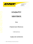
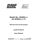
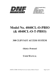
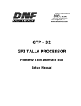
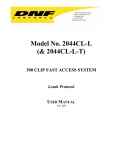
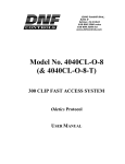
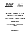
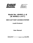
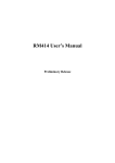
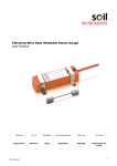
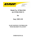
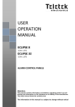
12843 Foothill Blvd.,
Suite D
Sylmar, CA 91342
818 898 3380 voice
818 898 3360 fax
www.dnfcontrols.com
Model No. ST400-CP
Protocol Description
&
USER MANUAL
ST400-CP User Manual
Page 1 of 19
Table of Contents
_____________________________________________________________________________________________
1. REVISION HISTORY
3
2. OVERVIEW
4
a.
b.
DESCRIPTION
FUNCTION CHART
4
5
3. INSTALLATION
5
4. POWER UP DEFAULTS
9
5. PROTOCOL DESCRIPTION
9
a.
b.
c.
d.
COMMUNICATIONS FORMAT
COMMANDS
CONFIGURATION TABLES
COMMAND EXAMPLES
6. SPECIFICATIONS
9
9
14
16
17
POWER CONNECTOR
SP2 Connector, RS232 PINOUT
SP2 Connector, RS422 PINOUT
17
17
17
7. KEY LAYOUT
18
8. DNF CONTROLS LIMITED WARRANTY
19
Manual Version …………..…….……………… 1.4 073004
Document No. …….…….……. ST400-CP User Manual.doc
ST400-CP User Manual
Page 2 of 19
1.
REVISION HISTORY
122203 Rev. 1.0
Original Document
010804 Rev. 1.1
Added Highlight Byte to the LCD command.
012304 Rev 1.2
Added RS422 Controller jumper configuration
071304 Rev 1.3
Added “I” command to draw tables.
073004 Rev. 1.4
Added “P” command to clear a part of the display.
ST400-CP User Manual
Page 3 of 19
2.
OVERVIEW
a.
DESCRIPTION
The ST400 will operate as an event driven device, transmitting information to the External Control
System (ECS) when a change is detected.
In addition, the ECS may poll the ST400-CP at any time for current status information.
Key Press Decoding
The ST400 will automatically detect and decode changes in the state of its 46 keys. It will return
the state of all keys on the keyboard any time there is a change detected. The state of the keyboard
is returned as 12 bytes, 6 bytes for Key Change bitmap (each key is represented by a bit) and 6
bytes for Key State bitmap of the key (each key is represented by a bit). If a bit is set in the Key
Change Bitmap – the corresponding key’s state was changed. If a bit is cleared in the Key Change
Bitmap, the corresponding key’s state was not changed. If a bit in the Key State bitmap is set – the
corresponding key is pressed. If the bit is cleared, the corresponding key is released.
Key LEDs
The Key LEDs are controlled by the ECS. Using appropriate commands, each led may be
individually controlled, turned ON or OFF. The ECS sends a five (5) byte, bit mapped value to
the ST400 to control the state of each LED. When a bit is set, the LED is turned on. When a bit
is cleared, the LED is turned off.
LCD Display
The LCD Display is controlled by ECS. Using appropriate commands, the ECS can display nullterminated strings at a specified row and column. It can display characters of 4 different sizes –
normal, double-high, double-wide and double-high-double-wide characters. It can also display
highlighted text and draw tables in various parts of the display.
Wheel
The Wheel mode is configured by ECS. Three different wheel modes are supported– Off, Jog, and
Shuttle (with mechanical detents). Wheel Position information will be automatically sent to the
ECS when wheel movement is detected and the current wheel mode is not OFF.
In OFF mode, the wheel will not return position information and the mechanical detents will not
be energized.
In JOG mode, the Wheel Position will be returned as a one byte, signed value that represents the
pulse rate (pulses per time period). A pulse rate of zero means that the wheel has not moved. A
positive position value represents Clockwise movement. A negative position value represents
Counter-Clockwise movement. The mechanical detents will not be energized in JOG mode.
In SHUTTLE mode, Wheel Position will be returned as a one byte, signed value that represents
the position of the wheel. When the SHUTTLE mode command is received, the ST400 sets the
current wheel position as the STILL or zero position of the wheel. The Wheel Position value
indicates movement of the wheel from the STILL position. A positive Wheel Position value
represents Clockwise wheel movement from the STILL position. A negative Wheel Position
value represents Counter-Clockwise wheel movement from STILL position. The mechanical
detents will automatically energize when the maximum clockwise or maximum counter-clockwise
Wheel Position value is reached. The mechanical detents will automatically de-energize when the
Wheel Position value is less than the maximums. Using appropriate commands, the wheel mode,
resolution, maximum clockwise, and maximum counter-clockwise values may be set.
ST400-CP User Manual
Page 4 of 19
T-bar
The T-bar is always enabled and will automatically send position information to the ESC when
movement is detected. The lowest point in its travel is the STILL or zero position. The T-bar
Position is a one byte, unsigned value that represents the position of the T-bar relative to the
STILL position. The T-bar cannot be configured by the ECS. It’s resolution, maximum and
minimum position values are set by the factory.
b.
3.
FUNCTION CHART
Control Panel
Functional Area
Controlled
By
Wheel Movement Detection
ST400
T-bar Movement Detection
ST400
Key Press Detection and Decoding
ST400
Wheel Mode Configuration
External Control System (ECS)
Key LEDs On/Off
ECS
LCD Display Text
ECS
INSTALLATION
a.
Connect the supplied power supply, Model AP4108, into the connector labeled POWER on the
rear of the ST400. Plug the Power Supply into a wall outlet, 90 VAC to 240 VAC.
b.
Plug one end of a 9-conductor, RS422 serial cable into the 9-pin connector labeled SP2 on the rear
of the ST400. Plug the other end of the cable into the 9-pin connector on the External Control
System (ECS).
c.
SP2 is configured for RS232 DTE when shipped from the factory. Refer to the following sections
“RS422 DEVICE Configuration” and “RS232 DTE Configuration”, to change the configuration
of SP2.
Installation is complete.
ST400-CP User Manual
Page 5 of 19
RS422- CONTROLLER Configuration
10A – JUMPER 1 TO 2, 3 TO 4, 5 TO 6, AND 7 TO 8
(Located behind the SP2 connector on the main pcb)
2
4
6
8
10A
1
3
5
7
10C – JUMPER 2 TO 3
10D – JUMPER 2 TO 3
10E – JUMPER 2 TO 3
10F – JUMPER 2 TO 3 (V4.1 pcb)
10H – JUMPER 1 TO 2 (V4.1 pcb)
(All located directly in front of 10A header)
10C 10D, & 10E
3
2
JUMPER - W1B, W2B. W3B, AND W5B
(Located between the SP1 and SP2 connectors on the main pcb)
2
2
2
2
2
1
W1
1
W2
1
W3
1
W4
1
W5
ST400-CP User Manual
Page 6 of 19
1
RS422 DEVICE Configuration
10A – JUMPER 1 TO 3, 5 TO 7, 2 TO 4, AND 6 TO 8
(Located behind the SP2 connector on the main pcb)
2
4
6
8
10A
1
3
5
7
10C 10D, & 10E
10C – JUMPER 2 TO 3
10D – JUMPER 2 TO 3
10E – JUMPER 2 TO 3
(All located directly in front of 10A header)
3
JUMPER - W1B, W2B. W3B, AND W5B
(Located between the SP1 and SP2 connectors on the main pcb)
2
2
2
2
2
1
W1
1
W2
1
W3
1
W4
1
W5
ST400-CP User Manual
Page 7 of 19
2
1
RS232 DTE Configuration
10A – JUMPER 1 TO 2 AND 5 TO 6 ONLY
(Located behind the SP2 connector, on the main pcb)
2
4
6
8
10A
1
3
5
7
10C 10D, & 10E
10C – JUMPER 1 TO 2
10D – JUMPER 1 TO 2
10E – JUMPER 1 TO 2
(All located directly in front of 10A header)
3
JUMPER – W4B ONLY
(Located between the SP1 and SP2 connectors on the main pcb)
2
2
2
2
2
1
W1
1
W2
1
W3
1
W4
1
W5
ST400-CP User Manual
Page 8 of 19
2
1
4.
POWER UP DEFAULTS
The ST400 powers up in the following default state:
The LCD display is blank.
All LEDs are off.
The wheel is set to OFF mode.
The ST400 is ready to receive commands from ECS.
5.
PROTOCOL DESCRIPTION
a.
COMMUNICATIONS FORMAT
Baud Rate
Parity
Data Bits
Start Bit
Stop Bit
b.
38.4K
ODD
8
1
1
COMMANDS
Command Format: STX + BC + CMD + DATA + CHECKSUM
STX =
BC =
0x02
Byte Count, 1 byte
Byte Count includes all data bytes between BC and Checksum, exclusively.
CMD =
1 byte
DATA =
Data bytes, command specific
CHECKSUM = Simple 8 bit sum of ALL preceding bytes (including STX)
ACK =
NAK =
STX + 01 + 0x04 + Checksum
STX + 01 + 0x05 + Checksum
ST400
External Control System
Key Change Command:
STX+ BC + ’K’+ KeyChange0 + KeyChange1 + … + KeyChange5 + KeyData0 + KeyData1 +
… + KeyData5 + ChecksumÆ Æ
BC: Byte count = 13
KeyChange0 … KeyChange5 – bitmap of the keys that have changed their state
If a corresponding bit is set - there was a change, if a bit is cleared – no change from the
previous state. See Keyboard Decode Table for bitmap decoding
KeyData0 … KeyData5 – state of the keyboard
If a corresponding bit is set - the key is pressed, if a bit is cleared – the key is released.
See Keyboard Decode Table for bitmap decoding.
Å Å No response required
NOTE- Key Press/Release status is sent on every key change. If all KeyData = 0, then all keys
have been released.
ST400-CP User Manual
Page 9 of 19
Key Change Status Request Command:
Å Å STX + 01 + ‘S’ + Checksum
STX+ BC + ’S’+ KeyData0 + KeyData1 + … + KeyData5 + Checksum Æ Æ
BC: Byte count = 7
KeyData0 … KeyData5 – state of the keyboard
IF a corresponding bit is set - the key is pressed, if a bit is cleared – he key is released.
See Keyboard Decode Table for bitmap decoding.
ST400
External Control System
Key LED Control:
Å Å STX + BC + ‘L’ + Led Data1 + Led Data2 + … + Led Data5 + Checksum
BC: Byte count = 6
Data1= LED1 (Lsb) to LED8 (Msb)
Data2= LED9 (Lsb) to LED16 (Msb)
Data3= LED17 (Lsb) to LED24 (Msb)
Data4= LED25 (Lsb) to LED32 (Msb)
Data5= LED33 (Lsb) to LED34 (Msb)
STX + 01 + ACK + Checksum Æ Æ
Wheel Mode:
Å Å STX + BC + ‘M’+ Wheel Divide + Min Position + Max Position +
Mode byte + Checksum
BC: Byte count = 5
Wheel Divide = 1 (highest resolution) to 96 (lowest resolution)
Min Position = The lowest number that may be returned as the wheel
position. It’s a signed value that ranges between 0 and –127.
Max Position = The highest number that may be returned as the wheel
position. It’s a signed value that ranges between 0 and +127.
Mode byte:
0= Off
1= Jog
2= Shuttle
STX + 01 + ACK + Checksum Æ Æ
Wheel Position: (Automatically sent when movement is detected)
STX + 02 + ‘W’ + Wheel Position Byte + Checksum Æ Æ
BC: Byte Count = 2
Wheel Position Byte = -16 Æ +16
Å Å No response required
T-bar Position: (Automatically sent when movement is detected)
STX + BC + ‘T’ + T-bar Position Byte + Checksum Æ Æ
BC: Byte Count = 2
T-bar Position Byte = 0 Æ +64
Å Å No response required
ST400-CP User Manual
Page 10 of 19
Wheel Position Request:
Å Å STX + BC + ‘W’ + Checksum
BC: Byte Count = 1
STX + 02 + ‘W’ + Wheel Position Byte + Checksum Æ Æ
BC: Byte Count = 2
Wheel Position Byte = -16 Æ +16
T-bar Position Request:
Å Å STX + BC + ‘T’ + Checksum
BC: Byte Count = 1
STX + BC + ‘T’ + T-bar Position Byte + Checksum Æ Æ
BC: Byte Count = 2
T-bar Position Byte = 0 Æ +64
ST400
External Control System
Blank the LCD Display:
Å Å STX + BC + “B” + Checksum
BC: Byte Count = 1
STX + 01 + ACK + ChecksumÆ Æ
When this command is received, the whole display is cleared.
Display On:
Å Å STX + BC + “N” + Checksum
BC: Byte Count = 1
STX + 01 + ACK + ChecksumÆ Æ
When this command is received, the display turns ON.
Display Off:
Å Å STX + BC + “F” + Checksum
STX + 01 + ACK + ChecksumÆ Æ
When this command is received, the display turns OFF.
ST400-CP User Manual
Page 11 of 19
LCD Display Text:
Å Å STX + BC + “D” + Row + Column + Size + Highlight Byte + Text (nullterminated) + Checksum
BC – Byte count of all bytes of the command excluding STX and Checksum
Row – Starting row of the display from 0 to 29
Column – Starting column of text – from 0 to 39
Size - 00 – Normal
01 – Double Wide
02 – Double High
03 – Double Wide, Double High
Highlight Byte – 00 – Highlight off (black characters on the white background)
01 – Highlight on (white characters on the black background)
Text – Up to 248 bytes of data, null terminated.
STX + 01 + ACK + ChecksumÆ Æ
NOTES:
The row and column are always set based on normal (the smallest) character size.
You should double the row number if you’re using Double High characters (size = 2 or 3) and you
should double the column number anytime you’re using Double Wide Characters (size = 1 or 3).
When the text reaches the end of line, it wraps around to the next line, starting with Column 0.
When the text reaches the bottom of the screen, it does not wrap around to the top of the display.
The text is truncated.
If there is no text added to the command (NULL-termination immediately follows the SIZE byte),
the specified row gets cleared (column byte is disregarded).
LCD Insert Table:
Å Å STX + BC + “I”
+ Border style (single-line or double-line)
+ Intersections style (single-line or double-line)
+ Number of Rows
+ Number of Columns
+ X coordinate of the Upper Left-hand Corner
+ Y coordinate of the Upper Left-hand Corner
+ Width of Column 1 (in characters)
+ ...
+ Width of Column n (in characters)
+ Height of Row 1 (in characters)
+ ...
+ Height of Row n (in characters)
+ Checksum
Where:
BC – Byte count of all bytes of the command excluding STX and Checksum
Single Line = 0
Double Line = 1
Number of Rows = 1 – 29
Number of Columns = 1 – 39
X coordinate of the Upper Left-hand Corner = 0 – 39
Y coordinate of the Upper Left-hand Corner = 0 – 29
The Width of an individual column may vary between 0 and 39 depending on the number of
columns defined (see Note 1 below)
The Height of an individual row may vary between 0 and 29 depending on the number of rows
defined (see Note 2 below)
STX + 01 + ACK + ChecksumÆ Æ
ST400-CP User Manual
Page 12 of 19
NOTES:
1. Total width of (Column1+ ...+ Column n) cannot exceed Maximum Width.
Maximum Width = Total Display Length – X coordinate of the Upper Left-hand Corner – Number of Lines
Total Display Length = 40 characters
Number of Lines = Number of Columns + 1
2. Total height of (Row1 + ... + Row n) cannot exceed Maximum Height
Maximum Height = Total Display Height – Y coordinate of the Upper Left-hand Corner – Number of Lines
Total Display Hight = 30
Number of Lines = Number of Rows + 1
3. All intersections are drawn in the same style lines (single-line or double-line depending on the specified style).
4. All outside boarders are drawn in the same style lines (single-line or double-line depending on the specified
style).
5. The display within the table will be cleared. The display outside the table borders will not be touched.
LCD Clear Part of the Display:
Å Å STX + BC + “P”
+ Number of Rows (height of the space to clear),
+ Number of Columns (width of the space to clear)
+ X coordinate of the Upper Left-hand Corner
+ Y coordinate of the Upper Left-hand Corner
+ Checksum
Where:
BC – Byte count of all bytes of the command excluding STX and Checksum
Number of Rows = 1 – 29
Number of Columns = 1 – 39
X coordinate of the Upper Left-hand Corner = 0 – 39
Y coordinate of the Upper Left-hand Corner = 0 – 29
STX + 01 + ACK + ChecksumÆ Æ
This command allows to clear a box on the display. All parameters assume small-size characters.
ST400-CP User Manual
Page 13 of 19
c.
CONFIGURATION TABLES
1)
LED Data Format Table:
LED DATA1:
Led ON: Bit= 1 Led
OFF: Bit= 0
Bit7= LED #8
Bit6= LED #7
Bit5= LED #6
Bit4= LED #5
Bit3= LED #4
Bit2= LED #3
Bit1= LED #2
Bit0= LED #1
Bit0= LED #17
LED DATA4:
Led ON: Bit= 1 Led OFF: Bit= 0
Bit7= LED #32
Bit6= LED #31
Bit5= LED #30
Bit4= LED #29
Bit3= LED #28
Bit2= LED #27
Bit1= LED #26
Bit0= LED #25
LED DATA2:
Led ON: Bit= 1 Led
OFF: Bit= 0
Bit7= LED #16
Bit6= LED #15
Bit5= LED #14
Bit4= LED #13
Bit3= LED #12
Bit2= LED #11
Bit1= LED #10
Bit0= LED #9
LED DATA5:
Led ON: Bit= 1 Led OFF: Bit= 0
Bit7= Undefined
Bit6= Undefined
Bit5= Undefined
Bit4= Undefined
Bit3= Undefined
Bit2= Undefined
Bit1= LED #34
Bit0= LED #33
LED DATA3:
Led ON: Bit= 1 Led
OFF: Bit= 0
Bit7= LED #24
Bit6= LED #23
Bit5= LED #22
Bit4= LED #21
Bit3= LED #20
Bit2= LED #19
Bit1= LED #18
ST400-CP User Manual
Page 14 of 19
2)
Keyboard Decoding Table:
In a Change Bitmap:
Bit = 1 – the key’s state has changed, Bit = 0 – the state has not changed.
In a State Bitmap:
Bit = 1 – the key is pressed, Bit = 0 – the key is released.
KeyData0:
Bit0= Key 1
Bit1= Key 2
Bit2= Key 3
Bit3= Key 4
Bit4= Key 5
Bit5= Key 6
Bit6= Key 7
Bit7= Key 8
KeyData3:
Bit0= Key 25
Bit1= Key 26
Bit2= Key 27
Bit3= Key 28
Bit4= Key 29
Bit5= Key 30
Bit6= Key 31
Bit7= Key 32
KeyData1:
Bit0= Key 9
Bit1= Key 10
Bit2= Key 11
Bit3= Key 12
Bit4= Key 13
Bit5= Key 14
Bit6= Key 15
Bit7= Key 16
KeyData4:
Bit0= Key 33
Bit1= Key 34
Bit2= Key 35
Bit3= Key 36
Bit4= Key 37
Bit5= Key 38
Bit6= Key 39
Bit7= Key 40
KeyData2:
Bit0= Key 17
Bit1= Key 18
Bit2= Key 19
Bit3= Key 20
Bit4= Key 21
Bit5= Key 22
Bit6= Key 23
Bit7= Key 24
KeyData5:
Bit0= Key 41
Bit1= Key 42
Bit2= Key 43
Bit3= Key 44
Bit4= Key 45
Bit5= Key 46
Bit6= Undefined
Bit7= Undefined
ST400-CP User Manual
Page 15 of 19
d.
COMMAND EXAMPLES
ST400
External Control System
1) Keyboard status request with the response that indicates that all keys are released.
ÍÍ 0x2 + 0x01 + ‘S’ + 0x56
0x2 + 0x07 + ‘S’ + 0x00 + 0x00 + 0x00 + 0x00 + 0x00 + 0x00 + 0x5C ÎÎ
2) Instruction to turn on LEDs 1 and 9.
ÍÍ 0x2 + 0x06 + ‘L’ + 0x01 + 0x01 + 0x00 + 0x00 + 0x00+ 0x56
0x02 + 0x01 +0x04 +0x07 ÎÎ
ST400-CP User Manual
Page 16 of 19
6.
SPECIFICATIONS
Power:
90 VAC to 265 VAC adapter supplied with IEC connector
APX Model #AP4108
+5v @ 4A, +12v @ 1.0A, -12V @ 0.6A
Size:
[L” x W” x H”] 12 3/4” x 8” x 1 3/4” (front) 3 5/8” (rear)
[8 5/8” high to top of display]
Weight:
10 lbs.
Rear Panel Connectors:
VTR1, 2, 3, 4, 5, 6, 7, 8
GPI
Power
Keyboard
Ref. Video In
Ground
Display:
Easy to read, back-lit LCD display
Jog/Shuttle Wheel:
With mechanical detents
(All DB9F)
(DBF25F)
(DB9M)
(6-pin mini DIN)
(BNC)
Threaded stud
POWER CONNECTOR
9-Pin D-Type, Female (DB9M)
Pin #
1
2
3
4
5
+5v DC
+5v DC
Ground
+12 VDC
–12 VDC
6
7
8
9
+5 VDC
Ground
Ground
Ground
SP2 Connector, RS232 PINOUT
9-Pin D-Type, Female
Pin #
1
2
3
4
5
No connection
Receive Í
Transmit Î
No connection
Ground
6
7
8
9
No connection
No connection
No connection
No connection
SP2 Connector, RS422 PINOUT
9-Pin D-Type, Female
Pin #
1
2
3
4
6
Frame Ground
Transmit A Î
Receive B Í
Ground
No connection
ST400-CP User Manual
6
7
8
9
Page 17 of 19
No connection
Transmit B Î
Receive A Í
Frame Ground
7.
KEY LAYOUT
ST400-CP User Manual
Page 18 of 19
8.
DNF CONTROLS LIMITED WARRANTY
DNF Controls warrants its product to be free from defects in material and workmanship for a period of one (1) year
from the date of sale to the original purchaser from DNF Controls.
In order to enforce the rights under this warranty, the customer must first contact DNF’s Customer Support
Department to afford the opportunity of identifying and fixing the problem without sending the unit in for repair. If
DNF’s Customer Support Department cannot fix the problem, the customer will be issued a Returned Merchandise
Authorization number (RMA). The customer will then ship the defective product prepaid to DNF Controls with the
RMA number clearly indicated on the customer’s shipping document. The merchandise is to be shipped to:
DNF Controls
12843 Foothill Blvd., Suite D
Sylmar, CA 91342
USA
Failure to obtain a proper RMA number prior to returning the product may result in the return not being accepted, or
in a charge for the required repair.
DNF Controls, at its option, will repair or replace the defective unit. DNF Controls will return the unit prepaid to
the customer. The method of shipment is at the discretion of DNF Controls, principally UPS Ground for shipments
within the United States of America. Shipments to international customers will be sent via air. Should a customer
require the product to be returned in a more expeditious manner, the return shipment will be billed to their freight
account.
This warranty will be considered null and void if accident, misuse, abuse, improper line voltage, fire, water,
lightning or other acts of God damaged the product. All repair parts are to be supplied by DNF Controls, either
directly or through its authorized dealer network. Similarly, any repair work not performed by either DNF Controls
or its authorized dealer may void the warranty.
After the warranty period has expired, DNF Controls offers repair services at prices listed in the DNF Controls Price
List. DNF Controls reserves the right to refuse repair of any unit outside the warranty period that is deemed nonrepairable.
DNF Controls shall not be liable for direct, indirect, incidental, consequential or other types of damage resulting
from the use of the product.
###
ST400-CP User Manual
Page 19 of 19