1
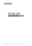
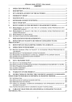
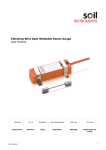
“Acoustic Control Systems” Ltd.
OPERATION MANUAL
Ultrasonic Thickness Gauge
A1207 / A1207C
Moscow, 2005
ULTRASONIC THICKNESS GAUGE - A1207 (A1207C)
2
Acoustic Control Systems, Ltd.
Moscow, 2005
ULTRASONIC THICKNESS GAUGE - A1207 (A1207C)
1.
GENERAL INFORMATION................................................................. 4
1.1.
1.2.
1.3.
2.
GENERAL APPLICATION........................................................................... 4
DESCRIPTION ............................................................................................ 5
DELIVERY SET........................................................................................... 7
DEVICE OPERATION......................................................................... 8
2.1. PREPARATIONS TO MEASUREMENTS ................................................... 8
2.2. MEASUREMENTS
USING
PRESET
ULTRASOUND
VELOCITIES .......................................................................................................... 8
2.3. MEASUREMENTS AND ADJUSTMENT OF DEVICE................................. 9
3.
ADDITIONAL ADJUSTMENTS OF THE DEVICE............................. 11
3.1. ADJUSMENTS ON THE KNOWN VELOCITY IN TESTIND
MATERIAL ........................................................................................................... 12
3.2. ADJUSTMENT ON THE ARBITRARY ULTRASOUND
VELOCITY IN TESTING MATERIAL WITH THE KNOW THICKNESS ................ 13
3.3. SET OF THE LOW THICKNESS LIMIT..................................................... 16
4.
TECHNICAL SPECIFICATION ......................................................... 17
5.
PRINCIPLES OF OPERATION......................................................... 18
6.
SOME NOTES ON OPERATION ...................................................... 19
7.
MAINTENANCE WORKS ................................................................. 21
7.1.
7.2.
7.3.
RECHARGING OF ACCUMULATORS ..................................................... 21
ADAPTATION TO THE PROBE’S NOISE LEVEL..................................... 21
REPLACEMENT OF THE PROBE’S CAPSULE ....................................... 22
8.
WARRANTY ..................................................................................... 24
9.
ATTACHMENT ................................................................................. 26
3
Acoustic Control Systems, Ltd.
Moscow, 2005
ULTRASONIC THICKNESS GAUGE - A1207 (A1207C)
1.
GENERAL INFORMATION
1.1.
GENERAL APPLICATION
A1207 and A1207C are small hand-held Ultrasonic Echo-pulse Thickness Gauges in a
form of marker-pen, designed for general thickness measurements. A1207C is a special
version of A1207 that is equipped with single crystal probe (“C” in the end of the marking
means ‘single crystal probe’).
A1207 – is applicable for measurements of wall thickness on tubes, pipes (including
pipe-turns), pressure vessels, boilers and other subjects from black and non-ferrous
metals with flat and corroded surfaces, which roughness is up to Rz160 and curvature
radius is from 10 mm. The range of thickness for measurements on steel is 0,8 up to 30
mm.
A1207C – is applicable for measurements of height for rails and other metallic subjects
with surface roughness up to Rz160 and curvature radius from 40 mm. Range of
thickness for measurement on steel is 10 up to 200 mm.
Range of ultrasound velocity in the testing materials can vary from 1000 to 9000 m/s.
As a couplant can be used different technical oils, glycerin, gel and other.
Operating conditions for these devices are as follows:
•
•
•
Environmental temperature: -30°C up to +50°C;
Relative humidity 85% at 25°C;
Atmosphere pressure up to 106,7 kPa
4
Acoustic Control Systems, Ltd.
Moscow, 2005
ULTRASONIC THICKNESS GAUGE - A1207 (A1207C)
1.2.
DESCRIPTION
3
10
9
1
4
6
2
7
8
5
рис. 1.
1.Electronic unit in the plastic case
2. Digital light-emitting diode display
3. Capsule of piezoelectric transducer
4. On/Off button
5. Ultrasonic velocity choice button
6. Plug for charging unit
7. Finger holders
8. Cap
9. Clip for wearing on clothes
10. Additional set up buttons
A1207 is equipped with double crystal piezoelectric probe on 10MHz operating frequency
and with 6 mm operating surface diameter.
A1207C version is equipped with single crystal probe on 5MHz operating frequency and
with 10 mm operating surface diameter.
The structure of A1207 and A1207C allows replacing the probe’s capsule in case of
5
Acoustic Control Systems, Ltd.
Moscow, 2005
ULTRASONIC THICKNESS GAUGE - A1207 (A1207C)
wearing. This replacement can be made by the operator himself and is described in the
item 7.3 of this manual.
The digital light-emitting diode display makes possible the application of the device in a
wide range of temperatures (from -30°C up to +50°C). The device should be switched on
right before the measurement. The power on condition of the device is indicated with four
strokes on the display or result of thickness readings or any other information on the
display.
The continuous operating time from the built-in accumulator is not less then 24 hours.
Recharging of the accumulator is made through the special plug [6] (Pic 1). Time of
charging is about 11 hours. It is also possible to work with the external power supply that
should be connected to the same plug.
For adjustment of the ultrasound velocity in testing material there is a button for choice
of ultrasound velocity [5] (Pic 1). Usually there are four most frequently used velocity
meanings for structural alloys are preset in the device.
5400 m/s
5950 m/s
6060 m/s
6300 m/s
Stainless Steel
Low-alloyed Steel
Steel 40Х13
Aluminium Alloy D16
For more exact adjustment of the ultrasound velocity for a particular material there are
three additional (hidden) buttons [10] in the device. These buttons are hidden behind
the front panel of the case (Pic 1). With these buttons you can set the meaning of
ultrasound velocity from 1000 up to 9000 m/s with a step of 10 m/s. These set-up buttons
allows the operator adjust the meanings of four saved velocity meanings under his own
testing materials and then choose them already with external button of velocity choice.
Besides with the help of these additional buttons the operator can also set the following
parameters:
•
•
•
•
Time interval, that compensates signal’s delay time in prisms of ultrasonic probe;
The lower limit of measuring thickness range;
Contrast level of the display;
Dimension of the testing readings (metric or English).
All the set characteristics of the thickness gauge are saved after turning off the device
and at empty accumulators.
There are also finger holders on the device’s case that stop fingers when measuring,
special clip for wearing the device on the clothes and a cap that has two purposes at the
same time:
•
•
It protects the surface of the probe from damaging during transportation and
storage.
It efficiently covers the probe’s surface with contact liquid.
6
Acoustic Control Systems, Ltd.
Moscow, 2005
ULTRASONIC THICKNESS GAUGE - A1207 (A1207C)
1.3.
DELIVERY SET
The basic delivery set for A1207 (A1207C):
№
Description
Quantity
1.
Ultrasonic Thickness Gauge A1207 (A1207C) with built-in
accumulator and built-in probe
1 item
2.
Cap
1 item
3.
Clip for wearing on clothes
1 item
4.
Bag
1 item
5.
External charging unit for A1207 (A1207C)
1 item
6.
Steel control testing block for A1207
1 item
7.
Passport of the device
1 item
8.
User’s Manual
1 item
As the additional accessories to the basic set there are also available:
•
•
•
•
Probe’s capsule on 10 MHz (5 MHz);
Accumulator NiMH (1,2V);
Cable for external power supply;
Spare nameplates
7
Acoustic Control Systems, Ltd.
Moscow, 2005
ULTRASONIC THICKNESS GAUGE - A1207 (A1207C)
2.
DEVICE OPERATION
2.1.
PREPARATIONS TO MEASUREMENTS
Attention! Before starting measurements clean the surface of the testing object from dirt,
friable rust or calx and then put enough contact liquid on the area of testing
2.2.
MEASUREMENTS USING PRESET ULTRASOUND VELOCITIES
To measure object’s thickness you need to do following:
Press On/Off button
On the display you will see four horizontal
strokes.
Press and hold the button of velocity choice.
On the display you will see the preset meanings
changing each other in 2-3 seconds. When you
see the necessary meaning, appearing on the
display, leave the button.
Put the device on the testing object and hold it 12 seconds until you get the thickness readings,
screened on the display.
8
Acoustic Control Systems, Ltd.
Moscow, 2005
ULTRASONIC THICKNESS GAUGE - A1207 (A1207C)
Notes: When you hold the device on the testing surface there is an
indication of an acoustic contact on the display.
•
In a metric system in the upper left corner you will see the symbol
as at the picture on the right.
•
In Imperial system in the lower right corner there is a symbol as
presented on the picture.
In a case of a bad contact with the surface the symbol will disappear.
Take the device from the object and see the
result of the reading. The reading will be
screened during 7-10 seconds and then will be
changed on four horizontal strokes.
Sometimes at the moment, when you take the
device of the object, the reading can change. In
this case you need to repeat measurement.
2.3.
MEASUREMENTS AND ADJUSTMENT OF DEVICE
If you get doubtful readings, when measuring thickness, you may need to test the device.
For that you need to use the steel testing sample block that is in the basic set of the
device.
To test the device (both A1207 and A1207C) you need to do the following:
Press the On button.
9
Acoustic Control Systems, Ltd.
Moscow, 2005
ULTRASONIC THICKNESS GAUGE - A1207 (A1207C)
On the screen you will see horizontal strokes.
With the help of Velocity choice buttons set the
ultrasound velocity for the control steel sample
block.
Put the device on the control block and hold for 12 seconds, until the reading stops changing on
the display.
Take the device of the block and see the result of
testing. The device’s reading should be the same
as the real thickness of the sample block.
If the reading of the device differs from the real thickness of the block, then you will have
to adjust the threshold unit of the device under the new noise level of the probe (see item
7.2) and then test the device one more time.
10
Acoustic Control Systems, Ltd.
Moscow, 2005
ULTRASONIC THICKNESS GAUGE - A1207 (A1207C)
3.
ADDITIONAL ADJUSTMENTS OF THE DEVICE
Under the holes on the front panel there are internal buttons for additional adjustments
of the device.
“menu”- chooses the item of the adjusted parameter;
“+” / “-“ – increase or reduce the adjusted parameter.
These buttons make it possible for the
operator to adjust the preset meanings of
ultrasound velocity under the velocity in the
given materials.
After that the adjusted and saved meaning
of velocity can be chosen with the help of
velocity choice button.
+
-
menu
Besides with the help of these additional buttons the operator can also set the following
parameters:
•
•
•
•
Time interval, that compensates signal’s delay time in prisms of ultrasonic probe;
The lower limit of measuring thickness range;
Brightness level of the display;
Dimension of the testing readings (Metric or Imperial).
Attention!
The changed meaning of ultrasound velocity is being saved in the device memory
with pressing velocity choice button.
There are 8 (eight) items in the “hidden menu” of the device:
•
First four items of the menu are the preset meanings of the ultrasound velocity.
«1» - 5400 m/s,
«2» - 5950 m/s,
«3» - 6060 m/s,
«4» - 6300 m/s;
• «5» – meaning of time delay of the signal in the probe’s prism;
• «6» - meaning of the minimal thickness that can be measured;
11
Acoustic Control Systems, Ltd.
Moscow, 2005
ULTRASONIC THICKNESS GAUGE - A1207 (A1207C)
• «7» - Brightness level of the display (in general there are 7 levels in the device
from 0 till 6);
• «8» - dimension of the results of measurement (English or metric).
METRIC (Euro) – all the results will be in metric units.
IMPERIAL (Inch) – all the results will be represented in Imperial units.
All the adjusted and saved in the memory parameters will be saved after turning off the
device.
3.1.
ADJUSMENTS ON THE KNOWN VELOCITY IN TESTIND MATERIAL
To adjust the device on the known velocity you need to do the following actions:
Press On / Off button.
On the screen you will see horizontal strokes.
Press menu button with a thin stick.
On the screen you will see “One”. This is the item
of the Menu to which the new meaning will be
saved. Pressing the Menu button you can choose
the necessary item in the menu.
To change the meaning of ultrasound velocity
saved on the chosen location («1» ÷ «4»), you
have to press one time «+» or «-» button and the
velocity meaning, that was saved in this item of
menu, will start to change.
12
Acoustic Control Systems, Ltd.
Moscow, 2005
ULTRASONIC THICKNESS GAUGE - A1207 (A1207C)
Note: In this case on the screen you will see on 10 m/s higher (or lower) meaning,
(depending on which button you have pressed) then the preset meaning on this menu
item
To set the new meaning you should press these
buttons («+» or «-») until you have the necessary
figures on the display. You can change the sound
velocity in the range from 1000 up to 9000 m/s
with the step of 10 m/s.
To save the set velocity, press the button of
velocity choice.
3.2. ADJUSTMENT ON THE ARBITRARY ULTRASOUND VELOCITY IN
TESTING MATERIAL WITH THE KNOW THICKNESS
When you work with the material, ultrasound velocity for which is not known, you can
adjust the device with the help of sample block made from the same material as the
object of testing. When you don’t have the sample block you can measure the thickness
of the object (if it is possible) with the exact measuring device, such as slide gauge or
micrometer. And then you can adjust the device the same way as adjustments by the
sample block.
For example, you need to test the object from steel of the unknown type. For that you
need to do the following steps:
4.9
5,4мм
Measure the thickness of the sample block.
13
Acoustic Control Systems, Ltd.
Moscow, 2005
ULTRASONIC THICKNESS GAUGE - A1207 (A1207C)
Press On button.
On the screen you will see the horizontal strokes.
With the help of Velocity Choice button choose
the rarely used meaning of ultrasound velocity,
that can be changed (for ex. 5400 m/s)
Put the device on the sample block.
On the display you will see the reading that will be
the approximate thickness of the sample.
Notes: If the reading of the device differs from the thickness of sample block, you need to
change the ultrasound velocity (see art. 3.1 of this manual). The right ultrasound velocity
can be picked up or calculate from the following equation:
С = С1·d1/d,
where С – the calculated ultrasound velocity,
С1 – the chosen ultrasound velocity,
d1 – the real thickness of the sample block,
d – the measured with the device thickness of the sample block
For example:
С=5400·5,4/5,1=5720 m/s – the necessary ultrasound velocity.
14
Acoustic Control Systems, Ltd.
Moscow, 2005
ULTRASONIC THICKNESS GAUGE - A1207 (A1207C)
Change the ultrasound velocity in the device. Put
the device on the sample block and compare the
real thickness with the readings of the device.
If it is necessary you will need to repeat these actions until the device shows the same
thickness of the sample block as it’s real thickness is. Each time you change the meaning
of ultrasound velocity you have to save it in the memory of the device (see art.3.1 of this
manual).
15
Acoustic Control Systems, Ltd.
Moscow, 2005
ULTRASONIC THICKNESS GAUGE - A1207 (A1207C)
3.3.
SET OF THE LOW THICKNESS LIMIT
Compulsory limitation of the low limit in the range of measured thicknesses allows to
avoid the wrong readings of the device.
The low limit (the minimal thickness) can be set with the internal buttons. It is the item
“6” of the menu.
For A1207 it is typical to set the low limit in the range from 0,4 up to 10 mm with a step
0,1 mm. Regularly the low limit set in the device (for steel) is 0,8 mm.
In A1207C version the range of low limit that can be set is from 0,4 to 100 mm with the
step of 0,1 mm. The minimal thickness meaning regularly set in the device for steel is 10
mm.
The procedure of setting the arbitrary minimal thickness is similar to the procedure of
velocity settings (see art. 3,2 of this Manual).
16
Acoustic Control Systems, Ltd.
Moscow, 2005
ULTRASONIC THICKNESS GAUGE - A1207 (A1207C)
4.
TECHNICAL SPECIFICATION
Parameters
Metric units
Inch units
Range of thickness for measurement on
steel:
А1207
А1207С
0.8…30 mm
10…250 mm
0,03…1,18 in
0,24…10,2 in
Step of thickness indication:
0,1 mm
0.002 in
Main error of measurements
± (0.005 *x + 0,1 mm),
± (0.005 *x + 0.002 in),
where X – thickness reading
where X – thickness reading
Range of ultrasound velocities in materials:
1000…9000 m/s
0.394…3.540*105 in/s
• 6 mm
• 10 mm
• 6 mm
• 10 mm
Power supply: (NiMH accumulator, 1,2V)
850 mAh
850 mAh
Duration of non-stop operation from the full
accumulator:
24 h
24 h
Temperature:
Relative air humidity:
Atmosphere pressure:
-30º С…+50º С
85% at t +25º С
84 ÷ 107 kPa
-30º С…+50º С
85% at t +25º С
84 ÷ 107 kPa
Sizes:
143х26х18 mm
143х26х18 mm
Weight with power supply elements:
55 g
55 g
Diameter of probe’s operating surface:
•
•
on 10 MHz (А1207)
on 5 MHz (А1207С)
Operation conditions:
17
Acoustic Control Systems, Ltd.
Moscow, 2005
ULTRASONIC THICKNESS GAUGE - A1207 (A1207C)
5.
PRINCIPLES OF OPERATION
A1207 and A1207C operate on the ultrasonic pulse-echo principle. The device measures
the time of double travels of ultrasonic oscillations through the material from one surface
to another. This time is recalculated to the meaning of thickness.
Ultrasonic probe, which is integrated in the case of the device, operates as sending and
receiving element for ultrasonic oscillations and their reflections.
This probe is put on the testing surface in the point where the thickness should be
measured.
If there are hollows on the opposite surface then ultrasonic pulses will be reflected from
the hollows and the thickness will be equal to the destination from the upper surface to
these hollows.
18
Acoustic Control Systems, Ltd.
Moscow, 2005
ULTRASONIC THICKNESS GAUGE - A1207 (A1207C)
6.
SOME NOTES ON OPERATION
Factors that can influence the operation of the device and exactness of readings.
State of the surface.
Loose or exfoliating rust, corrosion or dirt on the surface of testing object can influence
the ultrasound transmission to the material. That’s why before measuring on such a
surface you need to clean it from rust and calx and put more contact liquid then when
testing on flat surfaces.
Cleaning of the rough corroded surfaces can not only make the readings more exact but
also it can prolong the life-time of the ultrasonic probe.
If there is a thick layer of paint on the surface and the paint started to exfoliate, it is also
necessary to remove it. The thick paint reduces the level of signal and can make a false
echo, and that courses to the wrong readings of the device. The measuring can be made
through a thin layer of paint that is about 0,1 – 0,3 mm. But you will have to take into the
account that the thickness of the paint layer will be added to the result of measuring.
How you put the probe on the surface.
To have a good transmission of the ultrasound into the material you need to press the
probe tightly to the surface of the object.
When you measure the wall thickness of cylindrical objects, especially of small
diameters, it is recommended to use tough contact liquids and put more liquid on the
point of contact. Electro-acoustic screen (that is the line on the operating surface of the
probe) in A1207 should be directed perpendicular to the tube’s axle. Pressing the probe
to the tube’s surface and watching the readings of the device, you need to lean the probe
from side to side in the plane perpendicular to the tube’s axle. Move the probe step by
step along the tube’s wall, do not slide with it. The device’s readings when leaning from
the middle are increasing a little.
For a real thickness of the wall take the minimal stabile reading of the device at
contacting the tube’s wall with the middle of the probe’s operating surface. When the
probe leans strongly from this position the readings of the device will change in leaps and
bounds.
Objects with double convex curvature (tube’s turning, spherical coverings and so on) –
are the most difficult for testing, because the contact with them is only possible in one
point. The probe should contact the object with the middle of it’s operating surface.
Non-parallelism or eccentricity.
If the external and internal surfaces of the testing material are not parallel or are eccentric
to each other, then the reflected wave (the echo-pulse) deviates from the necessary
direction and the exactness of readings decreases.
19
Acoustic Control Systems, Ltd.
Moscow, 2005
ULTRASONIC THICKNESS GAUGE - A1207 (A1207C)
Acoustic characteristics of material.
Some characteristics of constructive materials can essentially limit the exactness of
measurement and range of measured thickness.
1. Sound dispersion
In some materials (for example, some types of stainless steel, cast-iron, composites) the
sound energy is dispersing (on crystallite moulding or on additions in composites). This
effect reduces the possibility of quality receipt of reflected from back-side signal and
because of that limits the possibility of ultrasound testing.
2. Velocity changes.
In some materials there are essential changes of ultrasound from point to point inside the
material. In some types of stainless cast steel and copper this effect is coursed by the
relatively big sizes of grains and by anisotropy of sound velocity with respect to the grain
orientation.
20
Acoustic Control Systems, Ltd.
Moscow, 2005
ULTRASONIC THICKNESS GAUGE - A1207 (A1207C)
7.
MAINTENANCE WORKS
7.1.
RECHARGING OF ACCUMULATORS
When the accumulators are almost empty, this
state will be indicated with four red dots blinking
on the display.
Charging is made through the special plug in the
gauge’s case with the help of the charging unit,
delivered in the basic set of the device. Time of
charging is 10 hours.
Notes: You can use the device while it is being charged without any limitation, but the
time of charging will increase.
7.2.
ADAPTATION TO THE PROBE’S NOISE LEVEL
During the exploitation because of wearing of the probe the level of its noises is
continuously increasing.
To have low possibility of wrong readings you need from time to time (approximately 1
time pro week) adapt the device to the new noise level of the ultrasonic probe.
Before the adaptation of the device, you need to wipe the probe’s surface until it is
fully dry.
When power off press velocity choice button
and holding it press On button.
On the display you will see four symbols.
21
Acoustic Control Systems, Ltd.
Moscow, 2005
ULTRASONIC THICKNESS GAUGE - A1207 (A1207C)
After that leave the velocity choice button.
On the display you will see horizontal strokes. In
1-2 seconds they should blink, and that will mean
that the device is ready for work.
7.3.
REPLACEMENT OF THE PROBE’S CAPSULE
When the probe’s capsule is worn out it is possible to replace it. For that, do the following
actions:
Unstick the nameplate from the rear side of the
device.
Loose two screws that fasten two parts of the
case.
Take the front panel of the case off.
22
Acoustic Control Systems, Ltd.
Moscow, 2005
ULTRASONIC THICKNESS GAUGE - A1207 (A1207C)
Take the plate out of the case.
Seal the cables from the capsule off the plugs on
the plate and take it from its frame.
Put the new capsule in A1207 in such a way, that
the separating line on its operating surface is
parallel to the width of the device’s case.
When replacing the probe’s capsule you need
carefully solder the marked cable from the
sending prism to the lamella of the X1 plug and
another cable of the receiving prism – to the
lamella of X2 plug. Pay attention to the
polarization of signal and screen wires.
After that you need to assemble the device and adapt it to the new probe’s noise level
(see art. 7.2 of this manual).
After you have replaced the probe’s capsule you need to check the exactness of
measurement on the testing samples. A1207 is tested on the testing samples with known
ultrasound velocity in them with the thickness of 0,8 – 30 mm. The A1207C version is
tested on the samples of 10 – 250 mm thick. If the readings of the device at testing differ
from the real thickness of the samples on more then 0,1 mm, then you need to set the
time, that compensate the signal delay in probe’s prisms. The procedure of this setting is
similar to the setting of ultrasound velocity (see art. 3.1 of this Manual). This is item 5 of
the Menu. At setting the time you need to reduce it, if the readings of the device less then
the real thickness of the samples, or increase the time, if the readings are higher then the
real thickness.
23
Acoustic Control Systems, Ltd.
Moscow, 2005
ULTRASONIC THICKNESS GAUGE - A1207 (A1207C)
8.
WARRANTY
Acoustic Control Systems Ltd. (ACS Ltd.) warrants the device for 1 year from the date of
sale, excluding the transducer. The standard warranty period for the transducer is 3
months from the date of sale. If something happens to the device during the warranty
period for reasons covered by the warranty, ACS Ltd. at its option will:
•
•
Repair the Product or
Replace the product if is unable to repair it.
This warranty does not cover damages due to external causes, including accident, usage
not in accordance with product instruction, misuse. The warranty also looses its validity if
the customer tried to repair the device himself or under mechanical effect the device
became nonrepairable.
For all the questions of repair, spare parts replacement and delivery of additional
accessories, such as clip for the wearing on the cloths, additional cable for external
power supply and additional nameplates, call manufacture under the following address:
Acoustic Control Systems Ltd. (“AKS”)
Russia, 119048, Moscow, PO.Box 148, “AKS”
Tel. / Fax. (095)244-31-94, 244-25-35, 245-58-96
E-mail: [email protected]
Website: www.acsys.ru
24
Acoustic Control Systems, Ltd.
Moscow, 2005
ULTRASONIC THICKNESS GAUGE - A1207 (A1207C)
Production number:
Sales date
Checking
Period of checking - 1 year.
INFORMATION ABOUT REPAIRMENT
Date
Damage type
Kind of repair
Sign of execution
25
Acoustic Control Systems, Ltd.
Moscow, 2005
ULTRASONIC THICKNESS GAUGE - A1207 (A1207C)
9.
ATTACHMENT
Velocity of Longitudinal ultrasonic waves in materials, m/s
Aluminium
Rubber
Aluminium alloyD16T
Lead
Beryllium
Silver
Phosphorus bronze
Glass ceramic
Vanadium
Steel
Stainless steel
Bismuth
Tungsten
Iron
Gold
Canoe
Kapron
Constantan
Ebonite
Epoxy resin
Copper
6260
1480
6320
2160
12800
3600
3530
6740
6000
6060
5400
2180
5460
5850
3240
2787
2640
5240
2400
2580
4700
Plexiglas
Brass
Soda-lime glass
Tantalum
Magnesium
Textolite
Manganin
Teflon
Manganese
China, porcelain
Chrome
Molybdenum
Zinc
Nickel
Zirconium
Tin
Cast iron
Osmium
Plexiglas
Polystyrene
2550
4430
5500
4235
5790
2920
4660
1350
5561
5340
6845
6290
4170
5630
4900
3320
5000 – 5600
5478
2670
2350
26
Acoustic Control Systems, Ltd.
Moscow, 2005
ULTRASONIC THICKNESS GAUGE - A1207 (A1207C)
27
Acoustic Control Systems, Ltd.
Moscow, 2005