1
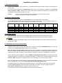
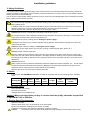
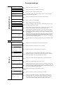
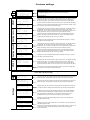
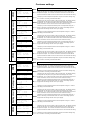
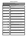
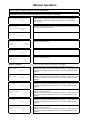
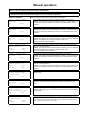
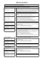
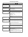
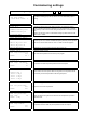
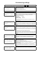
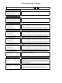
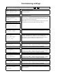
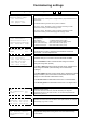
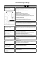
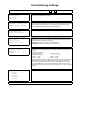
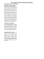
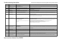
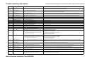
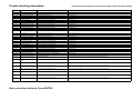
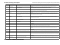
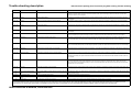
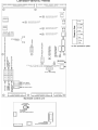
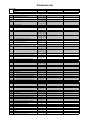
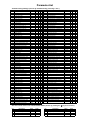
Trouble-shooting description
Disconnect the polarity proof connector plug befor solving Trouble shooting
Report no. Origin
Reason/Problem
Solution (when done solving the problem push the Enter button)
Display is blank and none of the green lights on the I/O
board are lit
Fuse F16 is broken or connection (clamps1,3) could be interrupted; level
indicator or STB defective.
Change fuse F16 (see the according scheme) or check the connection at clamps 1 and 3; check level indicator and STB connections!
Fuse F10 or control panel are broken
Change fuse F16 (see the according scheme), check the ribbon cable that connects the board and the control panel, contact the service department if those
measures can't remove the problem.
-"-
and green light H3 is not lit (while H4-H6
are)
-"-
and green light H3 is glowing
Ribbon cable isn't correctly connected or control panel is broken.
Check the ribbon cable or replace the cable or the control panel;
-"-
2 black bars that are displayed
EPROM is missing or plugged in incorrectly, control panel is broken
Plug in an EPROM at the backside of the control panel (according to the scheme on the guard plate) ; replace EPROM if it was plugged in incorrectly or
replace the control panel;
----
Display light not lit
Display light is broken
Contact the service department, replace the control panel;
----
Fault light doesn't work
Fuse F17 destroyed by short circuit or fault light not connected
fix the short circuit; correctly connect D40 or fault light;
001
Safety thermostat (STB)
Over temperature at boiler or STB connection jammed
Cool down the boiler below 90°C; remove STB protection cap and press the button, else have STB connection checked by an electrician; (short term
emergency operation is possible, see "operation without hardware test" at the end of error description)
002
Overcurrent stoker auger
Combustion chamber jam-packed, stoker auger clogged with slag or debris
jamming rotary gate valve
While mode switch is set to "Manual"
- open the pusher grate (no.2) and where required, remove jammed debris or slag;
- check stoker auger, if the motor doesn't work correctly there most likely is debris stuck in the rotary gate valve; unscrew lid and remove pellets and debris;
-contact the service department if the motor still doesn't work properly;
003
Overcurrent extraction auger
Extraction auger motor not connected properly or defective (Capacitor);
Extraction auger jammed (water or humidity in the storage room); Level
indicator defective or not adjusted properly;
Debris stuck in the extract auger;
004
Thermal protection extraction auger
Extraction auger rough-running, jam-packed or jammed by debris; auger motor Treat like error no. 003; indication for this fault if the motor has been rough-running for a while orerror no. 003 occurs repeatedly.
(capacitor) defective.
005
Pusher grate rough-running
Pusher grate rough-running
Empty ash box - then press Enter. Run ash removal by pushing the + button while display no.3 is shown in "Manual mode". Then use the + and - buttons to
check if the pusher grate is working properly while display no.2 is shown in "Manual mode" (the current must not excceed 1,2A), otherwise contact the
service department;
006
Overcurrent pusher grate
Pusher grate jammed
see no. 005
007
Pusher grate won't open
Neither the open end position nor the closed end position have been correctly In "Manual" operation mode check if the pusher grate can be fully opened/closed using the +/- buttons; If it can't, contact the service department;
reached.
008
Pusher grate won't close
The closed end position hasn't been reached correctly (while the open end
position has).
see no. 007
009
Overcurrent cleaning device
Cleaning device is rough-running
In "Manual" operation mode, check if the cleaning device is rough running. If the current is close to or above 5A contact the service department;
0010
Flue gas sensor connected incorrectly
Reverse polarity (can only happen when commissioning the boiler) or I/O boardHave connection polarity checked by an electrician, else replace the sensor or the I/O board;
defective.
0011
Flue gas sensor interrupted
Sensor not connected or connection interrupted.
Unscrew the extraction auger's maintainance lid and remove jammed pellets, check the storage room for water leaks or humidity; try to run the motor in both
directions while the mode switch is set to "Manual"; Check the auger's direction of rotation by pressing the + and - buttons. If no jammed parts can be found,
check or replace the motor and capacitor;
While the mode switch is in "Manual" position and either display no.7 or no. 7a is shown, check the level indicator and it's orange diode as follows:
- if the display shows "empty" and the level indicator diode is lit while the intermediate bin is jammed, replace the level indicator;
If there is a pellet suction turbine, a jammed or defect turbine may be the origin If there is a suction turbine, perform the following steps while in "Manual" mode:
of the problem.
- briefly rotate extract auger (no.6) backwards, remove both hoses, remove jammed material and empty the hoses;
- start the suction turbine (no.5) and check it for free pass, where required clean the turbine;
Contact the service department if you find brown deposits.
After correction of defects, Press ENTER !
Connect sensor or replace connection; check clamps and make sure that plugs 74 and 75 are connected firmly, else replace sensor or I/O board;