1
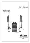
SP
OT
L
IG
4. CONTROL
CONTROLELEMENTS
ELEMENTS
3.
HT
12 MAIN LEVEL
This control sets the amount of signal simultaneously sent to the MAIN MIX
OUTPUT and TAPE OUT.
MAIN
15
15 10
9
9
0
0
14
OPERATING
11
9
9
15
15
0
13
0
dB
-10
LEVEL
12
-
63
160
400
1K
2.5K
6.3K
8
-30
+10dB
16K
13 LED METER
This meter has 4 leds with range of 30 dB to +10 dB (CLIP). The 0 led
corresponds to a level output of 0 dBu.The +10 led comes to life when the
output reaches +10 dBu. Set the MAIN LEVEL control so that the 10 led
only flashes occasionally. In general you get a good mix level when the Meter
leds operates in the range 10 to 0. If you exceed 0, you will get distortion.
If even 30 leds are sleeping your signal-to-noise ratio will suffer.
14 OPERATING
This LED indicates when your PBM4 is switched-on.
MASTER SECTION AND CONNECTIONS
22
DSP
15
16
1
2
MUTE
3
4
5
13
6
12
11
21
CLIP
DSP
MUTE
14
20
23
7
10
9
8
PRESETS
0
10
AUX/DFX RET
PRESETS
1.
2.
3.
4.
5.
6.
7.
8.
9.
10.
11.
12.
13.
14.
15.
16.
WARM HALL
BRIGHT HALL
WARM ROOM
BRIGHT ROOM
VOCAL 1
VOCAL 2
VOCAL 3
PLATE
STEREO DELAY1
STEREO DELAY2
REV + DELAY1
REV + DELAY2
REV + DELAY3
REV + DELAY4
REV + CHORUS1
REV + CHORUS2
18
FX SEND
19
FX RETURN
1
7
2
POWER AMPLIFIER
OUTPUT
MONITOR OUT
FOOTSWITCH
15
16
17