1
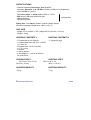
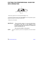
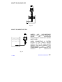
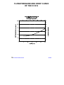
PROPORTIONAL INJECTOR D 30 S
USER’S MANUAL
SUMMARY
CHAPTER 1
INSTALLATION
.............................................................. PAGE 3
CHAPTER 2
PUTTING THE PROPORTIONAL
INJECTOR INTO OPERATION
............................................................ PAGE 15
CHAPTER 3
MAINTENANCE
............................................................ PAGE 19
D 30 S
DOSATRON INTERNATIONAL
1
SPECIFICATIONS
- Practical operating flow range : 8 to 30 m³ /h
- Operating pressure : 2 to 110 PSI (0.5 Bar to 8 Bar) for a temperature
lower than 40° C (104° F)
- Adjustable ratios : 1:400 to 1:80 (0.25% to 1.25%)
- 500 microns, 32 mesh protective filter
- Mixing chamber
- Hydraulic by-pass
incorporated
Fitting size : Inlet 2″ male thread, outlet 2‘’ female thread
Maximum operating temperature : 40° C (104° F)
UNIT SIZE
- Length 33”1/2 x width 17”2/3 x height 45”2/3 (85 x 45 x 116 cm)
- Weight : 24 kg
SHIPPING CONTENTS 1
SHIPPING CONTENTS 2
- 1 Proportional 8 m³/h Injector
- 1 suction intake tube 3/4’’ID x 1″1/8OD
or ∅ 20 x 28
- 1 By-pass tube 1/4″ID x 3/8″OD
or ∅ 6 x 9 mm
- 1 strainer
- 1 user’s manual
- 1 inlet adaptor + 1 nut to be fitted to
the turbo block
- 1 supporting legs
SHIPPING SIZE 1
SHIPPING SIZE 2
- 22”7/8 x 21”2/3 x 21”1/8
(58 x 55 x 41 cm)
34”2/3 x 28” x 1/4”
(88 x 71 x 6 cm)
SHIPPING WEIGHT 1
SHIPPING WEIGHT 2
- 23 kg
- 7 kg
2 DOSATRON INTERNATIONAL
D 30 S
CHAPTER 1
INSTALLATION
RECOMMENDATIONS
1-
GENERAL REMARKS
- In a case where the installation is higher than the Proportional Injector
unit itself, there is a possible risk of water flowing back through the unit.
Installation of a gate valve or non-return valve downstream is
recommended.
- Do not install the unit above a corrosive container (risk of fumes
attacking the Proportional Injector).
- Do not install the Proportional Injector on the suction side of the
supply pump (risk of siphoning).
2-
ASSEMBLY SHOULD BE CARRIED OUT WITHOUT TOOLS
3-
CLOUDY WATER
In the case of cloudy water, it is imperative to install a 300 microns 50 mesh filter upstream of the unit.
4-
WATER HAMMER
Installations subject to water hammer should incorporate a suitable
protection device such as a pressure regulator or expansion chamber.
For automatic installations, use slow opening solenoid valves.
For installations in different sectors, install the valves in cross mode,
i.e. as one opens, another one closes.
D 30 S
DOSATRON INTERNATIONAL
3
ASSEMBLY OF THE D 30 S
ASSEMBLY SHOULD BE CARRIED OUT WITHOUT THE USE OF TOOLS
WITH THE EXCEPTION OF THE WRENCH SUPPLIED FOR TIGHTENING
THE COUPLINGS.
The assembly of the Proportional Injector should be carried out in the
following order :
A
B
Fig. 1
D
C
C
D
B
A
E
- Remove the red protective caps (types A & B) from the Proportional Injector
and the turbo block inlets and outlets. Retrieve the spacing rings (D) and Orings (C) and fit them on to the inlet and outlet adaptors as shown in Fig. 1
(fit plastic spacing ring first, rubber O-ring second).
- Remove the protective caps (Fig. 1 - E) from the Proportional Injector
concentrate intake.
4 DOSATRON INTERNATIONAL
D 30 S
GENERAL VIEW
D 30 S
DOSATRON INTERNATIONAL
5
1/ First couple the stainless steel manifold A by the adaptor (Fig. 2 - A1) to the
Proportional Injector water outlet (note direction of arrow or Proportional
Injector).
A
Fig. 2
A1
2/ Couple the turbo block B, by the adaptor (Fig. 3 - B1) to the Proportional
Injector water inlet and by the threaded outlet to the manifold.
B
B1
Fig. 3
3/ Tighten the 3 nuts with the wrench supplied.
Fig. 4
6 DOSATRON INTERNATIONAL
D 30 S
4/ Fit the support legs to the manifold (T1 and T2).
A
T2
T1
Fig. 5
D 30 S
DOSATRON INTERNATIONAL
7
5/ Position the fixing plates (Fig. 6 - P) on the turbo block, fit the 4 washers
and wing nuts and tighten.
Fit the 2 spacing rods (Fig. 6 - M).
P
WATER
INLET
E
WATER
OUTLET
L
M
Fig. 6
8 DOSATRON INTERNATIONAL
D 30 S
CONNECTING TO THE WATER SUPPLY
NOTE ! You should obtain and fit the components necessary for
connection to the water supply depending on your installation.
Connect the unit to the water supply making certain that the water flows
in the direction of the arrow on the Proportional Injector body.
WHEN CONNECTING A SYSTEM EITHER TO THE PUBLIC WATER
SUPPLY OR TO ITS OWN WATER SOURCE, YOU MUST RESPECT THE
REGULATIONS IN FORCE CONCERNING PROTECTION OF THE
SOURCE I.E BACFLOW PREVENTION, ETC.
ADJUSTING THE DOSAGE RATIO
D 30 S
DOSATRON INTERNATIONAL
9
IMPORTANT ! Use no tools
RATIO ADJUSTMENTS MUST BE MADE WHEN THERE IS NO PRESSURE
IN THE UNIT
K
Fig. 7
Hold the lower part of the unit with the left hand and turn the barrel (Fig. 7 - K)
with the right hand until its upper edge is aligned with the required dosage.
10 DOSATRON INTERNATIONAL
D 30 S
INCORPORATED HYDRAULIC BY-PASS
A mechanism to select either the dosing function or the by-pass mode.
The control fluid must have a minimum pressure of 12 PSI (0.8 Bar) in order
to operate the by-pass.
ON
OFF
M
L
= Injecting function
= By-pass function
= Barbed fitting
= By-pass lever
M
L
M
L
Fig. 8
Fig. 9
By-pass mode :
- Put the lever (Fig. 8 - L) in the OFF position.
Dosing mode :
- Put the lever (Fig. 9 - L) in the ON position.
NOTE :
D 30 S
- When changing the lever (L) from the OFF to the ON
position, it is normal that a small jet of water escapes from
the barbed fitting.
- To stop the injection of the product, when the pressure of
your mains is outside the limits of the correct by-pass
operation (0.8 Bar to 8 Bar) (12 PSI to 120 PSI), take out the
suction pipe from the solution tank.
DOSATRON INTERNATIONAL
11
AUTOMATIC BY-PASS
A mechanism to select either the dosing function or the by-pass mode.
The control fluid must have a minimum pressure of 12 PSI (0.8 Bar) in order
to operate the by-pass.
M
N
OP
= 1/8″ barbed fitting (supplied with Proportional Injector)
= 1/4″ ID x 3/8″ OD flexible tube
= solenoid valve (not supplied with Proportional Injector)
L
M
N
O
P
Control fluid
(Air or Water)
Pressure of
12 PSI (0.8 Bar)
to 120 PSI (8 Bar).
Fig. 10
To operate the automatic by-pass :
- Open the solenoid valve (Fig. 10 - O).
- The by-pass control fluid is introduced.
- The Proportional Injector is put into the by-pass mode (injection stops).
To operate the injection function :
- Close the solenoid valve.
- The control fluid is turned off and the residue flows to waste (Fig. 10 - P).
- The injecting function is connected.
NOTE : Using the automatic by-pass, L must be in the ON position.
12 DOSATRON INTERNATIONAL
D 30 S
Automatic anti-siphon valve for additive :
- This automatically recreates normal atmospheric pressure in the
Proportional Injector in the event of an accidental vacuum in the line (Fig. 18
- Q).
Its use depends on the regulations in force in your country. You must comply
with the local water authority’s requirements.
- To put it into operation, unscrew the nut (Item. Q), remove the solid metal
disc and replace it by the washer supplied with the Proportional Injector.
Ball
Rubber washer
Metal washer
Fig. 11
D 30 S
DOSATRON INTERNATIONAL
13
14 DOSATRON INTERNATIONAL
D 30 S
CHAPTER 2
PUTTING THE
PROPORTIONAL
INJECTOR INTO
OPERATION
MAXIMUM FLOW
If your Proportional Injector clicks more than 36 times, that is 18 cycles in 15
seconds, you have exceeded MAXIMUM FLOW.
You should therefore install an Proportional Injector with a higher flow
capacity.
D 30 S
DOSATRON INTERNATIONAL
15
PUTTING THE PROPORTIONAL INJECTOR
INTO OPERATION
L
Fig. 12
- Place the by-pass lever in the ON position (Fig. 12 - L).
- Connect the product suction tube with strainer to the Proportional Injector
fitting and immerse it in the stock solution tank.
- Slowly turn on the water.
IMPORTANT !
- Ensure that the strainer is a least 4″ (10cm) above
the bottom of the tank to avoid sucking up the
insoluble particles that may damage the Proportional
Injector assembly (Fig. 13).
- Do not put the strainer on the ground.
NOTE :
The time required to prime the unit depends on the rate of water
flow.
16 DOSATRON INTERNATIONAL
D 30 S
WHAT YOU SHOULD DO
Fig. 13
WHAT YOU MUST NOT DO
UNDER
NO
CIRCUMSTANCE
SHOULD THE SOLUTION LEVEL BE
ABOVE
THE
DOSATRON
PROPORTIONAL INJECTOR WATER
INLET LEVEL.
WHEN CONNECTING A SYSTEM
EITHER TO THE PUBLIC WATER
SUPPLY OR TO ITS OWN WATER
SOURCE, YOU MUST RESPECT THE
REGULATIONS
IN
FORCE
CONCERNING PROTECTION OF THE
SOURCE
IE
BACKFLOW
Fig. 14
D 30 S
DOSATRON INTERNATIONAL
17
FLOW/PRESSURE MINI DROP CURVE
OF THE D 30 S
18 DOSATRON INTERNATIONAL
D 30 S
CHAPTER 3
MAINTENANCE
RECOMMENDATIONS
1-
When using soluble products to be made up into solutions, it is
recommended to periodically dismantle the entire injecting portion,
copiously rinse it with water and re-assemble it after having previously
lubricated the seal with a silicone lubricant W (Fig. 15).
Fig. 15
W
2-
An air inlet, an impurity or a seal’s failure can interrupt the injecting
function ; periodically check out that the product is correctly drawn up,
thus incorporated into the water.
D 30 S
DOSATRON INTERNATIONAL
19
TO CLEAN THE INCORPORATED FILTER
500 microns - 32 mesh
Frequency : Once per month depending on use.
Fig. 16
Filter
Seal V
Fig. 17
20 DOSATRON INTERNATIONAL
D 30 S
To remove the filter :
- Close the valve upstream of the unit and allow the pressure to drop.
- Unscrew the bell housing by hand and remove it.
Note ! Water will flow from bell housing.
- Carefully remove the piston assembly holding it upright (Fig. 19 - page 22).
- Remove the seal V (Fig. 17 - page 20).
- Remove the filter.
- Clean it and rinse in clear water.
To reassemble the filter :
- Before re-assembly ensure that the filter supports and seal V are clean and
free of foreign bodies.
- Apply silicone grease to the thread on the body.
- Then proceed in reverse order to the above.
IMPORTANT : IN ALL CASES TIGHTENING MUST BE DONE BY
HAND.
D 30 S
DOSATRON INTERNATIONAL
21
HOW TO DRAIN THE UNIT
R
W
Seal
V
Q
Fig. 18
Fig. 19
(In case of frost risks)
1/ Close the valve upstream of the unit.
2/ Allow the pressure to drop.
3/ Close the valve downstream of the unit.
4/ Once the valves upstream and downstream of the unit have been shut off :
- Unscrew the bell housing by hand (Fig. 18 - Rep. R), and remove it.
- Lift out the piston assembly taking care to hold it upright (Fig. 19) so that
the plunger seal (Fig. 22 - Rep. Y) engages correctly in the sleeve.
If the seal does not engage in the sleeve, refer to the procedure for
dismantling the dosing assembly (Fig. 19).
- Empty the body by turning upside down (Fig. 19 - Rep. W).
- Draining is now completed and the unit can be reassembled, having first
lubricated the thread on the body with silicone grease.
22 DOSATRON INTERNATIONAL
D 30 S
CHANGING SEALS IN THE INJECTOR
ASSEMBLY
(White part)
IMPORTANT ! Use no tools
1 - CHANGING THE PISTON PLUNGER SEAL
a/ Unscrew the bell housing by hand and remove it (Fig. 20).
b/ Remove the piston assembly holding it upright (Fig. 21).
c/ Remove the seal Y (Fig. 22 - page 24).
Fig. 20
D 30 S
Fig. 21
DOSATRON INTERNATIONAL
23
- If it is found necessary to
remove the piston plunger, pay
attention when replacing it to
screw it in until you reach a
stop, and not to overtighten it.
There should be some play in
the plunger allowing it to be
easily
inserted
into
the
Proportional Injector body.
Piston plunger
Y
Fig. 22
24 DOSATRON INTERNATIONAL
D 30 S
2 - CLEANING AND RE-ASSEMBLING OF THE SUCTION VALVE
3
- Unscrew the black nut and pull downwards to release the valve.
- Change the flat valve seal.
- Change also the O-ring (item 3).
D 30 S
DOSATRON INTERNATIONAL
25
FAULT FINDING
FAULTS
1 - MOTOR
INCIDENTS
DIAGNOSIS
REMEDIES
Check that your
installation allows a
correct operation of
Proportional Injector.
e.g. direction of flow.
YOUR PROPORTIONAL
INJECTOR DOES
NOT START OR STOP
Check that the water is
ON or that the solenoid
valves are energised
(switched on).
The by-pass is either
closed or half opened.
Open the by-pass (page
11).
Clogged up filter.
Clean up the filter
(see page 20).
Maximum flow
exceeded.
Unscrew the bell housing.
Remove the piston and
ensure that the 2 lower
valve seals and the 4
higher valves seals are in
their correct positions.
Reduce the flow, and put
again into operation.
Damage in the Injector Return the Proportional
body.
Injector to us.
THE PROPORTIONAL
INJECTOR WORKS IN
SPITE OF USING THE BYPASS (STOP OF THE
INJECTING SOLUTION)
The pressure of your
mains system, after
the Proportional
Injector, is inferior to
12 PSI before it.
The flow is higher than
the maximum flow.
PLUNGER DETACHED
Too high pressure.
FROM THE PISTON MOTOR
26 DOSATRON INTERNATIONAL
Increase the pressure
(110 PSI max.) or set up
the Proportional Injector
in by-pass mode with
isolating valves.
Fit a new plunger.
D 30 S
FAULTS
DIAGNOSIS
REMEDIES
2 - DOSING
INCIDENTS
WATER FLOWING BACK
INTO THE SOLUTION
TANK
Worn out or contaminated
seals.
Clean or change the
suction valve (see p. 25).
NO SUCTION OF
PRODUCT OR UNDER
DOSING
The hydraulic motor is
stopped.
See above Chapter
MOTOR INCIDENTS
(page 28).
Check out the suction
height.
Important ! The limit is 4 m
(13 feet).
Reduce it if necessary.
Air inlet in the suction pipe.
Check the tighteness of
the black nut at the
lower end of the
Proportional Injector
body and the clamp
ring on the suction
intake tube.
Blocked suction tube or
clogged up strainer.
Clean these items
Important : Avoid
putting the strainer at
the bottom of the drum.
Always leave a
minimum of 10 cm (4″).
Suction of air.
Maximum flow exceeded.
Worn plunger or plunger
seal.
Worn Proportional Injector
body.
Reduce the flow.
Change.
Change.
IMPORTANT !
In case of leaks between the pump body (blue) and the Proportional
Injector body see page 28 – LEAKS.
D 30 S
DOSATRON INTERNATIONAL
27
FAULTS
DIAGNOSIS
REMEDIES
3 - LEAKS
LEAKS BETWEEN THE
(BLUE) BODY AND THE
PROPORTIONAL
INJECTOR BODY
Watertight seal is badly
positioned.
Check the seal :
Hold the black nut (item
A) to prevent its turning
and unscrew the sleeve
loosen the interior screw
(item B).
Note ! Take care to align
the components when reassembling.
LEAKS BETWEEN THE
BODY AND THE BELL
HOUSING
Seal V absent or badly
positioned (see Fig. 17 page 20)
Remove the bell
housing, clean the seal
seating and put back the
seal.
Apply silicone grease to
the thread and screw on
the bell housing keeping
it upright.
CONNECTION LEAKS
Seal is badly positioned or
cut.
Position it correctly or
replace it.
Pipe is not correctly
inserted.
Insert it correctly.
DOSATRON INTERNATIONAL
DECLINES ALL RESPONSIBILITY IF THE PROPORTIONAL INJECTOR IS USED UNDER
CONDITIONS OUTSIDE OF ITS OPERATING TOLERANCE AS INDICATED HEREIN.
28 DOSATRON INTERNATIONAL
D 30 S
This document does not form a contractual engagement on the part of DOSATRON INTERNATIONAL and is
for information only.
The company reserves the right to alter product specification or appearance without prior notice.
D 30 S
WARRANTY
DOSATRON INTERNATIONAL, will replace any part
considered as originally defective during the first 12
months from the date of purchase.
This guarantee will operate provided that the faults
noted do not come from a defective installation or
misuse of the Proportional Injector.
Any damage caused by the use of a tool will not be
covered by the manufacturer’s warranty.
DOSATRON INTERNATIONAL
29
KNOW YOUR FLOW……………………………….A SIMPLE METHOD
THE DOSER IS COMPOSED OF :
- A driving volumetric hydraulic piston motor.
- A dosing piston.
The speed rhythm of the motor is proportional to the flow of water passing
through the system. Thus the rate of injection will likewise remain
proportional. In its reciprocating motion the piston motor « clicks ».
Once in the up position
Once in the down position
SMALL MODEL : Count the number of clicks in 90 seconds x 10
= Flow of water in litres/hour.
D 30 S MODEL : Count the number of clicks in 30 seconds x
400
= Flow of water in litres/hour.
30 DOSATRON INTERNATIONAL
D 30 S
Rue Pascal - B.P. 6 - 33370 TRESSES (Bordeaux) FRANCE
Tel.33(0)557971111 – Telex 541931F-Fax33(0)557971129
http://www.dosatron.com – E.MAIL : [email protected]
PATENTED PRODUCTS
D 30 S
DOSATRON INTERNATIONAL
31