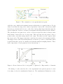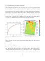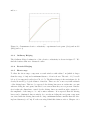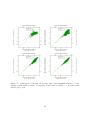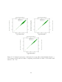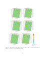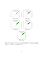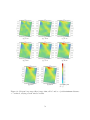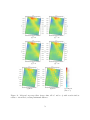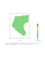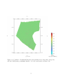
1
Faculty of Sciences Factorial Kriging of Soil Sensor Images using ISATIS Sam Vanloocke Master dissertation submitted to obtain the degree of Master of Statistical Data Analysis Promotor: Prof. Dr. Ir. Marc Van Meirvenne Tutor: Ir. Eef Meerschman Faculty of Bio Engineering Department of Soil Management Academic year 2011-2012 Faculty of Sciences Factorial Kriging of Soil Sensor Images using ISATIS Sam Vanloocke Master dissertation submitted to obtain the degree of Master of Statistical Data Analysis Promotor: Prof. Dr. Ir. Marc Van Meirvenne Tutor: Ir. Eef Meerschman Faculty of Bio Engineering Department of Soil Management Academic year 2011-2012 The author and the promotor give permission to consult this master dissertation and to copy it or parts of it for personal use. Each other use falls under the restrictions of the copyright, in particular concerning the obligation to mention explicitly the source when using results of this master dissertation. Foreword First of all I would like to thank my promotor Prof. Marc Van Meirvenne. He was the one who introduced me to, and made me enthousiastic about the scientific field of spatial statistics. He provided me with an interesting research topic where I could contribute due to its novelty. He also helped me with providing much insight into the topic, while still keeping an open mind when I found something interesting. Eef Meerschman, my tutor, showed great interest into my topic, and was always prepared to listen to me and discuss. I hope that she enjoys early motherhood, and I really appreciate the time we worked together. Ellen Van De Vijver did do a great job serving as a substitute tutor for Eef when she was home, recovering from childbirth, but even before that I enjoyed our conversations about geostatistics and faits divers. Thanks go to Timothy Saey and Valentijn Van Parys for their work attaining and cleaning up the data I would base my thesis on, and especially to Timothy for taking the time to give me background information which makes this thesis much more enjoyable to read, or so I hope. Now for the hidden person behind the man who did this, a special thanks goes towards my girlfriend Nele for being ever so patient with me and making me believe in myself, even as I frequently doubted myself. I hope I can provide the same support next year when she is working on her thesis. Contents 1 Abstract 1 2 Introduction 2.1 Goals . . . . . . . . . . . . . . . . . . . . 2.2 Theory . . . . . . . . . . . . . . . . . . . 2.2.1 Spatial statistics . . . . . . . . . 2.2.2 The variogram . . . . . . . . . . 2.2.3 Ordinary Kriging . . . . . . . . . 2.2.4 Factorial Kriging . . . . . . . . . 2.3 The datasets . . . . . . . . . . . . . . . . 2.3.1 Data collection methods . . . . . 2.3.2 Dense data . . . . . . . . . . . . 2.3.3 Anisotropy of density . . . . . . . 2.4 The software: ISATIS . . . . . . . . . . . 2.4.1 Short manual and ISATIS specific 2.5 Research procedure . . . . . . . . . . . . 3 Methods and Results 3.1 Initial method development . . . . 3.1.1 Data exploration . . . . . . 3.1.2 Experimental variogram and 3.1.3 Ordinary Kriging . . . . . . 3.1.4 Factorial Kriging . . . . . . 3.1.5 Short range . . . . . . . . . 3.1.6 Long range . . . . . . . . . 3.2 Testcase 1 . . . . . . . . . . . . . . 3.2.1 Data exploration . . . . . . 3.2.2 Experimental variogram and 3.2.3 Ordinary Kriging . . . . . . 3.2.4 Factorial Kriging . . . . . . 3.2.5 Short range . . . . . . . . . 3.2.6 Long range . . . . . . . . . 3.3 Testcase 2 . . . . . . . . . . . . . . 3.3.1 Data exploration . . . . . . 3.3.2 Experimental variogram and . . . . . . . . . . . . . . . . . . . . . . . . . . . . . . . . . . . . . . . . . . . . . . . . . . . . . . . methods . . . . . . . . . . . . . model . . . . . . . . . . . . . . . . . . . . . . . . model . . . . . . . . . . . . . . . . . . . . . . . . model . . . . . . . . . . . . . . . . . . . . . . . . . . . . . . . . . . . . . . . . . . . . . . . . . . . . . . . . . . . . . . . . . . . . . . . . . . . . . . . . . . . . . . . . . . . . . . . . . . . . . . . . . . . . . . . . . . . . . . . . . . . . . . . . . . . . . . . . . . . . . . . . . . . . . . . . . . . . . . . . . . . . . . . . . . . . . . . . . . . . . . . . . . . . . . . . . . . . . . . . . . . . . . . . . . . . . . . . . . . . . . . . . . . . . . . . . . . . . . . . . . . . . . . . . . . . . . . . . . . . . . . . . . . . . . . . . . . . . . . . . . . . . . . . . . . . . . . . . . . . . . . . . . . . . . . . . . . . . . . . . . . . . . . . . . . . . . . . . . . . . . . . . . . . . . . . . . . . . . . . . . . . . . . . . . . . . . . . . . . . . . . . . . . . . . . . . . . . . . . . . . . . . . . . . . . . . . . . . . . . . . . . . . . . . . . . . . . . . . . . . . . . . . . . . . . . . . . . . . . . . . . . . . . . . . . 2 2 3 3 3 7 10 12 12 13 14 15 15 17 . . . . . . . . . . . . . . . . . 18 18 18 19 19 20 20 21 25 25 26 27 28 28 28 31 31 31 3.4 3.3.3 Ordinary Kriging . . . . . . . . . . . . . . . . . . . 3.3.4 Factorial Kriging . . . . . . . . . . . . . . . . . . . 3.3.5 Short range . . . . . . . . . . . . . . . . . . . . . . 3.3.6 Long range . . . . . . . . . . . . . . . . . . . . . . New insights and theoretical considerations . . . . . . . . . 3.4.1 Computation times . . . . . . . . . . . . . . . . . . 3.4.2 Comparison of filtered images and real components 3.4.3 Separating local structures from global patterns . . . . . . . . . . . . . . . . . . . . . . . . . . . . . . . . . . . . . . . . . . . . . . . . . . . . . . . . . . . . . . . . . . . . . . . . . . 32 32 32 34 36 36 36 40 4 Discussion 44 A figures 46 B ISATIS manual 59 1 Abstract When dealing with dense spatially distributed numerical datasets, one frequently observes spatial variation acting on different scales simulateously. When trying to obtain these components individually, the common solution lies in applying a classical filtering method based on the spatial spectrum of the data, or on regularization. However these methods do not take advantage of the rich spatial variational information contained inside the data. In this thesis we try to gain insight and determine a workable method based on the Factorial Kriging equations. FK is a promising filtering method based on a statistical interpolation method called Kriging, that is based on the spatial variability of the data. Densely packed datasets that provide full area coverage provide an abundant and highly detailed source of information on the studied location. However with extra detail comes extra complexity. The first major finding of this thesis is that unlike the Ordinary kriging method, FK estimations can not rely on highly localised information alone, but requires information from all over the range of the component. In order to avoid exponentially growing computational requirements, a way to reduce complexity has to be found. This solution lies in using only a small subset of the data within the range of the component. We found that we can reduce the comutation times greatly by forcing a minimum distance between datapoints to be used for the estimation, a procedure that is unique for the software package ISATIS that was used in this thesis. This minimum distance be chosen a decent fraction of the range of the component while still retaining a decent quality of the filtered image. Unfortunately a limiting requirement seems to be that the minimum distance should be smaller than the range of all other components with a smaller range. We found some evidence that this limit is due to the inner workings of the implementation of the minimum distance in ISATIS, but no defenite proof has been found. Finally the Factorial Kriging procedure was used to filter localised structures from global patterns, even as the two have similar ranges and are thus hard to separate in the variogram. The pattern was modeled and the structures were filtered as the residual of the spatial variability within the considered range. 1 2 Introduction It is quite common that spatial variation of a property in the environment occurs on different scales simultaneously. The physical processes that bring about this variation are often caused by different sources. For example soil conditions and their variability arise from plant roots, agricultural activity and geological activity, all are processes that work on very different scales. The emergence of more and more detailed datasets that manifest variability on different scales, has necessated the investigation of nested variation. Factorial Kriging is a method based on Kriging estimation that utilizes this nested variation in order to produce filtered images that represent the physical property caused by only one component at a time. 2.1 Goals The main goal of this thesis is to provide a usable method for Factorial Kriging for high density datasets. Of primary importance is to find out what is the optimal configuration to calculate the Factorial Kriged (filtered) images. Apart from the correctness of the images we also want to find out what are the main restrictions for this method, and other aspects to be aware of. As a researcher often has to cope with time restrictions, this thesis should provide the user with ways to reduce the computation time but minimize their drawbacks, and some insight on how changing the configuration changes the computation time. The research will be conducted principally with the ISATIS software package, a powerful commercial geostatistical software package and one of the only software packages that provide a Factorial Kriging routine. One of the end results of this thesis is a user manual for Factorial Kriging for high density datasets when using ISATIS, so the reader can immediately test the method. 2 2.2 2.2.1 Theory Spatial statistics Geostatistics is a branch of statistics dealing with spatially distributed datasets. It has many applications among which mining, soil science, hydrology, environmental control and agriculture. It distinguishes itself from classical statistics in the underlying assumptions regarding the data. In classical statistics the data are generally assumed to be independent after removal of a trend, which means that it does not take into account any correlations between different data. In geostatistics it is normally assumed that the data are correlated, as nature generates only in rare cases phenomena without spatial correlation. The first major goal of a geostatistical analysis is to model this spatial correlation. The most used methods in geostatistics are prominently -but not restricted to- interpolation methods. Not all methods make use of the available correlational data, such as trend surfaces and inverse distance weighting, but those that do, generally give much better results. The most important method based on spatial correlation is Kriging. 2.2.2 The variogram In order to make estimations based on correlation between spatial data, one has to know how the variable at the location to be estimated, correlates with this variable in the surrounding area. Sometimes this information is given, but most of the time the correlation has to be estimated from the collected data. In order to do Kriging, some assumptions regarding the data have to be made. Suppose the variance between an observation Z(x) at a location x and a second observation Z(x+h) at x+h depends only on h. This means that the variance is a function only of h: V ar[Z(x+h) − Z(x)] = E[(Z(x+h) − Z(x))2 ] = 2γ(h) (1) γ(h) is the semi-variance of variogram function. Here the vector h represents the lag or spatial distance between two observations. An extra assumption has to be made regarding the mean: E[Z(x+h) − Z(x)] = 0 Or the mean m is supposed to be constant. Together these two assumptions 2 and 1 form the intrinsic hypothesis. 3 (2) The experimental variogram: In the simple case that the variable that is considered is correlated equally in all directions, -isotropical correlations-, the variogram function is one dimensional. From (1) we find that the variogram at a certain lag distance h can be estimated by averaging the mean squared difference of all pairs of observation at a distance h from each other. This can only be done in the case that the samples are taken from a regular grid. In an irregular grid we will find for each lag distance that is present in the sample, only one corresponding pair. In that case we can resort to indirect methods using a variogram cloud, or using lag classes. 2 The variogram cloud is simply the plot of the experimental values of (z(xi )−z(2 xi −h) against the lag distance h. It is often used in explorative data analysis to identify pairs of extreme differences. One can use a variogram cloud to fit a model directly, but due to the large amount of points it is often very impractical. Usually the experimental points are combined in a limited amount of lag classes. First a class width or lag separation has to be defined. This is analogous with creating a zone of two concentric circles around each sample location in real space. If another sample resides inside the aforementioned zone, it creates a pair that is used for the variogram calculation. This is done for all valid pairs. Afterwards the values are combined and averaged. The average lag distance is h and the average variogram value is γ(h). It is common that the largest lag distance of any class does not exceed half the largest dimension of the surface covering the data. This measurement avoids that some points are not represented in the variogram for large lag distances. If the experimental variogram is anisotropic or suspected to be, one can also define directional classes on top of lag classes γ(h, β). The directional classes indicate certain directions in the 2D space. Similar to lag separation, an angular tolerance is chosen: samples that reside inside the angular tolerance from the considered directional class, form valid pairs that are used for the directional variogram. Often a maximum bandwidth is also defined which determines the maximum Cartesian distance from a direction. This avoids the risk that a point is chosen that is far from the intended direction for large lag values. The variogram model: Typically the experimental variogram γ(h) is a function which increases from low values near the origin (low h) to larger values as h increases. Often this function stabilizes around a maximum for large h values. This maximum is called the sill. This sill represents the total variance. The lag h at which the sill is reached is 4 Figure 1: The construction of an experimental variogram called the range which is the maximal extent at which there is a spatial relation. For lag values lower than the range, there exists a dependence between the observations, which increases as observations lie closer to each other. At lag values larger than the range the expected difference between observations is maximal and independent from the distance. Theoretically the variogram is zero at h = 0. However in practice there is always a minimal distance between the two closest points. This can cause the variogram to have a positive value, even when extrapolated to the origin. The value at at the origin is called the nugget effect. The nugget represents a random noise term for the measured variable. The nugget can be caused by measurement errors but also by sources of variability caused by phenomena that operate at a smaller scale than the smallest sampling distance. These basic components of a variogram model are shown in fig. 2. Figure 2: Shown: Basic models of variograms: 1. Spherical; 2. Exponential; 3. Gaussian The fitting of a theoretical model to the experimental variogram in practice is often done using a select few mathematical functions. The mathematical limitations on the 5 possible functions are that the resulting matrix is invertible, and positive definite (see section 2.2.3). The following contains a list of the most commonly used models (a is the range), see also fig. 2: Nugget effect: γ0 (h) = 0; h = 0 γ0 (h) = C0 ; h > 0 Spherical model: γ1 (h) = C1 3h 1 − 2a 2 3 ! h ;0 < h ≤ a a γ1 (h) = C1 ; h > a Exponential model: 3h ;0 < h γ1 (h) = C1 1 − exp − a Gaussian model: 3h2 ;0 < h γ1 (h) = C1 1 − exp − 2 a Power: γ1 (h) = hω ; 0 < h; 0 < ω < 2 In the exponential and Gaussian models a practical range is used, defined by the hvalue for which the function reaches 95% of the sill C1 . If possible the Gaussian model is to be avoided as it causes instability during the inversion of the Kriging matrices see section 2.2.3). It represents a large degree of homogeneity of the variability over short distances. The power model is unbound. It represents increasing variability with increasing distance, and may indicate a spatial trend (non-stationary mean). However it is possible that the spatial dimension of the sampling area is chosen too small to capture the range of the underlying model. This non-stationarity of the second order can still fall under the assumptions of the intrinsic hypothesis as long as the increase is of less steep than h2 . 6 nested model: Any set of variograms can be summed and again form a variogram: γ(h) = γ1 (h) + γ2 (h) + ... + γn (h) This so called nested variogram can be used to describe complex patterns over multiple spatial scales. An often recurring combination is that of a nugget effect and a simple model. The components of a nested variogram need not necessarily represent any physically occurring phenomena, but if it does, it will facilitate the interpretation of the variogram and its resulting estimations. An example of a nested variogram is shown in figure 6a further ahead, where 2 spherical components are combined to fit the experimental anisotropic models: After the calculation of the experimental directional variograms it is often possible to find the two orientations in which the spatial variability has its largest continuity and smallest continuity (respectively the experimental variogram with the largest range and the shortest range, mostly these two directions are perpendicular). If the sill of all directional variograms are the same, and only the range changes as a function of the orientation, we are confronted with geometric anisotropy. The range of the variogram in any direction β can be found by first calculating the ellipse for which the major axes are the orientations of the two aforementioned variograms, and their lengths are their respective ranges, and subsequently calculating the distance between the origin and the point at which the ellipse cuts the direction of the variogram to be found. If the sill of the directional variograms are different, there is zonal anisotropy. This can be modeled by adding a second anisotropic structure with a very large range in one direction, so that this component disappears in the considered direction. variogram properties The variogram provides a measure of the statistical distance between two points. The smaller the variogram at a certain lag h, the more information both points have in common. 2.2.3 Ordinary Kriging As mentioned at the start of this chapter, the Kriging interpolation method is an estimation method that makes use of the spatial correlation of the data at hand. Deriving the Kriging estimation starts at the criteria of unbiased and optimal interpolation: E[Z ∗ (x0 ) − Z(x0 )] = 0 (3) s2 (x0 ) = E[(Z ∗ (x0 ) − Z(x0 ))2 ] = minimum (4) 7 With Z ∗ (x0 ) being the estimation at x0 and Z(x0 ) being its real value. Since the Kriging estimation method is a interpolation method, the interpolated value can be written as a weighted linear combination of measurements in the neighborhood around x0 : n(x0 ) X ∗ Z (x0 ) = λα Z(xα ) (5) α=1 In its most general form the general Kriging equation is: n(x0 ) ∗ Z (x0 ) − m(x0 ) = X λα [Z(xα ) − m(xα )] (6) α=1 In this form we do not have to suppose that the mean is stationary. For the Ordinary Kriging equation it is supposed that m(x) is locally stationary, which means that we suppose that in the neighborhood of x where measurements contribute to the Kriging estimation (6) the mean is supposed to be constant. Combining this assumption with the general equation (6) and supposing that the sum of the weights λα is equal to 1: n(x0 ) X λα = 1 (7) α=1 Yields the Ordinary Kriging estimator: n(x0 ) ∗ ZOK (x0 ) = X λα Z(xα ) (8) α=1 Equations (7) and (8) together should obey the two criteria of an unbiased and optimal interpolation (3) and (4). The first criterion is easilly checked, the second criterion requires the introduction of the variogram. After some mathematical manipulations the ordinary point Kriging system in terms of the variogram is attained. Pn(x ) 0 β=1 λβ γ(xα −xβ )+ψ=γ(xα −x0 );α=1,...,n(x0 ) n(x0 ) X λβ = 1 β=1 (9) Here ψ is a Lagrange multiplier used to add the condition (7) to the equation. Ordinary Kriging is also able to provide a measure of the precision of the interpolation, the Ordinary 8 Kriging variance s2OK : n(x0 ) s2OK (x0 ) = X λα γ(xα − x0 ) + ψ (10) α=1 It allows to estimate the relative precision of the Kriged estimates. The Ordinary Kriging system can be written in matrix form: [A][λ] = [B] (11) The solution can be found by inverting [A] and multiply with [B]: [λ] = [A]−1 [B] (12) This yields the weights λα which are used to find the estimator Z ∗ (x0 ) and its variance s2OK (x0 ). properties of the Kriging system The Kriging system does not use any information on the measurements directly. The measurements are used to construct the variogram γ(x) which are then used in the Kriging equations. Aside from this the Kriging estimates only depends on the spatial distribution of the observations. The Kriging equations also show us that next to the variogram between the observation points and the point x0 to be estimated (the [B] matrix), the variogram between the observation points (the [A] matrix) also plays a large role. Kriging is an exact interpolator, meaning that the estimation Z ∗ (xα ) at an observation point xα will be equal to the observed variable Z(xα ) and its associated Kriging variance s2OK (xα ) will be equal to zero. There are no restrictions to the weights apart from eq. 7. It is entirely possible that a weight is negative or larger than 1. This means that Kriging is able to extrapolate above or below extreme values, but this is not without its risks: it is possible that unphysical estimations are obtained. screening effect Kriging incorporates information on the sampling configuration. If multiple observation points lie closely together, the weights they receive for interpolation will decrease. Also the observation point closest to the point of estimation will receive the highest weight and subsequently the points lying behind the closest point will receive a lower weight, depending on the variogram. This phenomenon is called the screening effect. This is the result from the information contained in [A]. The observation closest 9 to x0 will contain the most information on Z(x0 ), so it takes priority over observations in its close neighborhood. Kriging has an inherent declustering effect. search neighborhood The neighborhood around x0 where the observations are taken into account to interpolate Z(x0 ) is called the search neighborhood. Usually the shape of this neighborhood is taken to be a circle in case of an isotropic variogram, or an ellipse if the variogram is anisotropic. The dimensions of the neighborhood are generally taken to be the ranges of the variogram, as observations lying at further distances are considered to be uncorrelated. The maximum number of neighbors to be used for interpolation can be limited to a small number, usually < 50. Observations at a large distance will generally receive a small weight, both due to a smaller correlation with Z(x0 ), and the screening effect from points closer to x0 . A minimum number of neighbors is usually also specified, between 2-5. When not enough points are in the search neighborhood, the interpolation is not performed and the non-interpolated points are usually reported as missing data. If observations are very inhomogeneously distributed, such as highly clustered data, it might be advantageous to divide the search neighborhood into segments. On top of the overall maximum and minimum neighbors, a maximum of points to be used per segment should be specified. This ensures that information in all directions from x0 is represented more or less equally. There are other interpolation method based on Kriging such as simple Kriging (without or with a trend surface, with varying local means), lognormal Kriging, block Kriging, coKriging, indicator Kriging,... 2.2.4 Factorial Kriging A statistical process Z(X) can be treated as a combination of different independent nested processes. If this is true, the variogram of Z(X), γ(h) itself is a combination of different variograms: γ(h) = γ 1 (h) + γ 2 (h) + ... + γ S (h) (13) If the processes are uncorrelated the total variogram can be written as a linear combination of S basic variograms g k (h): S X γ(h) = bk g k (h) (14) k=1 Here g k (h) is the k-th basic variogram used to construct γ(h), not necessarily in any particular order, and bk is the coefficient that represents the relative contribution of g k (h) 10 to the total variance. The components need not necessarily represent any physical process, but if they are modeled after such a process, mainly by manipulation of the range of the components, it will improve the interpretability of the resulting images. If second order stationarity is in order for Z(X), it can be represented as the sum of its components: S X Z(x) = Z k (x) + µ (15) k=1 with the expectation of Z k (x) equal to 0 and µ the mean of the variable. The squared differences are 1 0 0 E[(Z k (x) − Z k (x + h))(Z k (x) − Z k (x + h))] = δkk0 bk g k (h) 2 (16) with δkk0 = 1 if k = k 0 , and 0 otherwise. If the process is non-stationary, the last component Z S (x) with basic variogram g S (h) is unbounded with gradient bS . Each component Z k (x) can be estimated similarly to Ordinary Kriging (9). The estimation again is a linear combination of the values of its neighbors. However to obtain an unbiased estimation the sum of the weights should be equal to 0: Pn(x ) 0 λk γ(x −x )+ψ k (x )=bk g k (x ,x );α=1,...,n(x ) α α 0 0 0 β β β=1 n( x ) 0 X λkβ = 0 β=1 (17) with ψ k (x0 ) being the Lagrange multiplier for each component. The system has to be solved for each component and is of the same complexity as the Ordinary Kriging system. Each component will generally yield different λk -values and using these, the filtered image for each component can be constructed. Note that we do not need to know the solution of any component except for the considered component, to make a filtered image. This means that all components can be reconstructed independently. If there is a long range trend, this does not necessarily obstruct the reconstructions, as often we can assume the mean to be locally stationary in the search neighborhood of x0 . We can rewrite (15) as: S X Z(x) = Z k (x) + µ(x) (18) k=1 The local mean µ(x) can be considered a long range component. To be complete, the local mean also has to be estimated as a linear combination of the neighbors. The sum 11 of the weights is 1 to obtain unbiasedness. This can be done by Kriging: Pn(x ) 0 λ γ(x −x )+ψ k (x )=0;α=1,...,n(x ) α 0 0 β β β=1 n(x0 ) X λβ = 1 β=1 (19) To estimate a spatial component, the neighborhood should cover at least its range. However in dense dataset there are so many data inside this neighborhood that only a small portion of them are used in practice due to the screening effect. The biggest obstacle associated with solving the (Factorial) Kriging equations is the inversion of the matrix containing the interactions between the neighbors, and its complexity rises quickly with increasing neighbors. Also including a high amount of data tends to make the inversion of this matrix less stable. Furthermore distant points are generally shielded by the nearest observations so that the actual range of the neighborhood is smaller than the specified neighborhood. This means that the range of the estimated component will be smaller than the range determined by the earlier analyses (construction of variogram). Some solutions to this problem have been proposed. When working with data on a regular grid, Galli et al. (1984) proposed to use a smaller selection of the data only including every second or fourth point. This ensured that the data will be selected from all over the search neighborhood. Others have proposed to add the long range component and local mean together, so that the search window is only relevant for shorter range components, see Jaquet (1989); Goovaerts and Webster (1994). 2.3 2.3.1 The datasets Data collection methods A very useful way of taking measurements in a non-destructive way is by making use of the properties of the electromagnetic spectrum. For frequencies that are not too high, electromagnetic waves merely interact with soil by scattering without energy loss. Soils with different electromagnetic properties -such as permittivity and permeability- will scatter electromagnetic fields differently, and will thus result in image contrast when emitted and measured. The department of Soil Management of the Faculty of Bio-Engineering at UGent has high tech electromagnetic induction (EMI) measuring devices at its disposal. These devices are able to perform simultaneous measurements of electric conductivity and magnetic 12 susceptibility at different depths. The measurements of the electric conductivity and magnetic susceptibility were made using the DUALEM-21S. This sensor consists of a 2.41 m long tube, and has one transmitter and four receiver coils at a different spacing (see Fig. 3), but also with different orientations to perform measurements at different depths. The sensor is mounted on a non-metallic sled and pulled by an all terrain vehicle across the surface of the terrain of interest. In order to try to cover the terrain as fully as possible in order to attain a complete image of the terrain, the vehicle is driving in close parallel lanes back and forth with a distance that is as constant as possible. Obviously it is not always possible to drive straight forward because of obstructions like trees. However this shouldn’t necessarily lead to problems when analyzing the data. It just means that the information density at the location of the three will be less dense. A GPS was used to georeference the measurements with an accuracy of approximately 0.10 m. The GPS and sensor are connected to a field computer to gather their information. Measurements are made at constant time intervals, with a frequency of 8-10Hz. [5] Figure 3: Transmitter and receiver dipole orientations and coil spacings of DUALEM-21S 2.3.2 Dense data The fact that we are working with a dataset that fully covers the terrain of interest means that the data are very densely packed. This abundance of information leads to a few complications and theoretical consequences. As a consequence of the central limit theorem, a statistic converges asymptotically to a certain value as the sample size increases. If the used statistic is unbiased, the statistic 13 will be an unbiased estimator. The experimental variogram as a function of lag distance is an estimator of the spatial variability of the measured phenomenon. As the dataset is very large, the the amount of available couples for each lag class will be very large. This makes it possible to refine the experimental variogram, by using a smaller lag distance and more lag classes. If the lag distance is small enough, the experimental variogram will be a good approximation of the actual spatial variance at this distance, if the assumptions of 2nd order stationarity apply. If the the spatial variability is a smooth function of lag distance, the obtained experimental variograms will also behave very smoothly. This will be almost always the case when working with natural data, as natural phenomena seldomly are discontinuous. The high density of the data also means that the nugget of the experimental variogram will be a good approximation of the real nugget effect, except if phenomena working on a comparable or even smaller scale than the minimal lag distance are important for the measured variable. The nugget effect is a measurement of the noise of a variable. Since natural phenomena are rarely noisy, a very dense dataset will often show a very small nugget effect. The high density of the datasets will lead to problems regarding the inversion of the Kriging system (12). Since it is advised to use samples that completely cover the range of the variogram to calculate the solution of this matrix equation, the matrix tends to become very big. The inversion of a matrix tends to be very computer intensive with its growing size, so a large part of this thesis will be dedicated at attempts to mitigate this effect. 2.3.3 Anisotropy of density The density of the data is composed of two components as can be seen in figure 4. First there is the distance between two consecutive measurements inside the same driving lane. This is determined by the time between two measurements (constant), and the vehicle velocity which can fluctuate depending on the vehicle and and driver. The average distance inside a driving lane tends to be of the order of 10cm. The distance between nearby measurements on separate driving lanes is usually around 70cm. Of course these distances can be regulated to fit the requirements of the soil survey. The difference between the information density inside the driving lanes and between consecutive driving lanes leads to an anisotropy of information density, where generally the information density is highest parallel to the driving lanes and least dense perpendicular to the driving lanes. This might lead to complications for Factorial Kriging of a short 14 range component if its range is of the order of the intra driving lane distance. In that case the amount of information used in the direction parallel to the driving lanes might be much higher compared with the direction perpendicular to the driving lanes. This can lead to artifacts. The direction in which the vehicle moves alternates between consecutive driving lanes. This might lead to perturbations in the data which have to be dealt with during the post-processing stage of the data acquisition. However it is possible that small artifacts are still present during the stage of data analysis. 2.4 The software: ISATIS ISATIS is a Geostatistical software that can be used in all steps of statistical data analysis, ranging from data exploration, data analysis to the creation of complex images and data representations and simulation based on user created models. ISATIS is one of the only commercially available software packages that can perform Factorial Kriging, and handle non-regularly spaced datasets. Furthermore the fact that the user can force ISATIS to impose a minimum distance between samples (see further in this chapter) without the use of a predetermined subset of the data, makes this software a good choice to tackle the problems set by the research design. ISATIS does have its flaws however, such as its black box approach that impedes the user to have much direct control on the process, and ISATIS forcing the datapoint nearest to the location to be estimated to be included in the Kriging system when using a minimum distance. Most time intensive calculations are parallelized so working with a cluster of computers will decrease real time calculations significantly. 2.4.1 Short manual and ISATIS specific methods The ISATIS manual specific for handling the used dataset can be found in Appendix B. The search window Just like any software allowing Kriging estimations, ISATIS allows the user to define the search window. The search window is the area around the location to be estimated, from which the points used for interpolation can be included. The search window is an ellipse, and the user provides the length of its main axes (fig. 4a). Minimum distance between points ISATIS provides the user a useful setting for dealing with dense datasets. When doing a Kriging estimation one can ask ISATIS to choose a configuration of points so that each point in this configuration has a minimal 15 distance, provided by the user, to any other point in the configuration (fig. 4b). This allows the variable to be estimated to use information from a large area while limiting the amount of observations to be used. This method is different from other methods that reduce sample sizes such as estimation on a regular grid that is an interpolation from an irregular grid, or thinning out the sample size before applying the estimation method. When using this method, no information is thrown away a priori, and each location to be estimated makes use of a different subsample. A constant in the subset selection is that ISATIS always includes the datapoint that is nearest to the location to be estimated in the subset. (a) radius of search window (b) minimum distance Figure 4: The selection of samples to be used for estimation at the rectangle in the center Maximum number of points ISATIS allows the user to define a maximum number of points to be used for the estimation of the variable at a location. If more than this maximum amount of points lie within the restrictions -search window, minimum distance, points per segment- ISATIS tends to only choose the points nearest to the location to be estimated. As we do not want this number to influence the results of this thesis, it is always set very high (10000), unless stated otherwise. Images To make an image of an estimated component, ISATIS requires a regular grid with quantitative values. At each location of this regular grid the the variable to be 16 imaged should be estimated. One can avoid estimation at certain points or regions by making use of selection variables. 2.5 Research procedure To achieve the goal of finding an optimal configuration for Factorial Kriging, we will execute a parameter sweep, varying both the search window dimensions and the minimum distance. First we must define a regular grid which allows us to plot an image of the estimated variable. A satisfactory configuration will be achieved when the estimated image stabilizes thus if changing the parameter does not change the image qualitatively. This can also be evaluated by making a scatterplot of subsequent estimations and seeing if the points are located on the first bisection line, which indicates a perfect one-on-one match. 17 3 3.1 Methods and Results Initial method development The first dataset was collected on a rectangular field in Meigem (fig. 5). The dataset maps the electric conductivity up to a certain depth (fig. 6b). The measurements contains a network of polygonal crop marks caused by ice wedges during the glacial period, and a former field track running in a north-southeast direction. The data were attained using an EMI sensor. [6] Figure 5: (a) Aerial photograph showing polygonal crop marks and a former field track with a rectangle delineating the test area and (b) a closeup of the test area 3.1.1 Data exploration Due to the possible long range spatial trends it is often difficult to identify outliers. A value that is a local outlier might not so special when compared to values at that are far away which would make it hard to identify when displayed using classical data exploration methods such as a histogram. However variogram clouds often make it possible to identify local outliers. In the Meigem dataset, a few adjacent points are clearly different than others. In the upper left corner of figure 6b there is a small scale disruption with a large amplitude. This disruption is a clear departure from the overall spatial variational trend. However upon closer inspection, the disruption is not a discontinuity but a gradual but quick deviation from the local value. We decided to leave the outliers, also because it might provide some insight in how the Factorial Kriging procedure works. 18 3.1.2 Experimental variogram and model The experimental variogram has a smooth variation (fig. 6a). It was constructed using 20 classes with lag distance of 2 m with a maximum lag distance of 40 m. Larger lag distances than 40 m exceed half the largest dimension of the measured surface, and thus are not present in the variogram (see Chapter 2.2.2). When extrapolating the experimental variogram to a 0 m lag, the nugget effect seems to disappear entirely. A model was fitted with 2 components: a short range component with a range of 7 m and a sill of 4.5 mS m−1 , and a long range component with a range of 40 m and a sill of 6.5 mS m−1 . The short range component can be identified as the component corresponding with the ice wedges. No explanation has been found for the long range component. (a) Experimental Variogram (dots) and Model (line) (mS m−1 ) (b) Ordinary Kriging Image (mS m−1 ) Figure 6: Meigem: (left) Variogram, (right) Ordinary Kriging Image with outlier indicated by the arrow 3.1.3 Ordinary Kriging The Ordinary Kriging method was used to estimate the electrical conductivity on a regular grid. The used variogram model was the one described earlier. Each point used up to 5 nearest neighboring points in each of the 8 used sectors of space. This means that optimally 40 neighboring points are used, which is almost always the case. The sectors 19 were used to counteract the anisotropy of the sampling density (see Ch 2.3.3). The result of the Ordinary Kriging estimation can be seen in figure 6b. 3.1.4 Factorial Kriging The model contains two components, working at a short range of 7 m and one working on a longer range of 40 m. The information that is relevant for the long range component covers a much larger area around the location to be estimated than the small range component. As the time to invert the matrix A rises very quickly with the amount of points considered, we first execute the parameter sweep for the short range component and try to implement the learnt lessons for the long range component. 3.1.5 Short range First the search window is varied keeping the minimum distance between samples used for the estimation at zero. This means that all datapoints inside the search window will be included for the calculation of the filtered component image. We proceeded by Kriging the first variogram component for circular search windows, with different diameter lengths in steps of 1 m, from 1 m up to 8 m. In figures 25 and 26 it can be seen that the image of the short range component stabilizes when the search window reaches the range of the short range component. This is further illustrated in figure 27 which shows the scatterplots of consecutive images. As the search window increases the dots are located closer to the bisection line. This means that images tend to a stable configuration with increasing search window. If we look at the filtered images of the small range component for search windows smaller than the range of the considered component we see structures appear that have a smaller range than this component. This is not the result of any specific limits on shape that are set up but are purely resulting from the restriction of the area where information is used to make the filter. This also means that the screening effect (see Chapter 2.2) as used in Ordinary Kriging as a way of restricting the amount of datapoints to be used, does not apply in the same way for Factorial Kriging. Otherwise a search window with radius 7 m contains hundreds of datapoints which would be more than enough for the outer datapoints to be shielded by the ones closer to the location to be estimated. Subsequently we evaluate a series of Factorial Kriged images where the search window is kept fixed at 8 m, which is larger than the range, and we vary the minimum distance between points that are used for Kriging. The pictures (fig. 28) and the scatterplots (fig. 29) show that making the minimum distance larger has only a small influence on 20 the image quality. Making the minimum distance large enough to become a significant fraction of the search window dimensions, leads to the image becoming slightly more grainy. The fact that the minimum distance can be pretty large before significant loss of quality ensues is a good sign. This means that it might be possible to only use a small subsection of the available data to estimate the filtered component at one location. This could reduce computation times drastically. There seems to be no clear and distinct value at which the minimum distance still yields a good image, but when increased the image quality deteriorates quickly. This enables the user to adapt the minimum distance according to his needs. It appears that using a minimum distance that is a large fraction (such as 1/3) of the range of the considered component still results in a good image. A clear image of the filtered short range component is found in figure 7(a). It shows the polygonal network caused by the ice wedges without much influence of other sources. 3.1.6 Long range First the minimum distance is kept constant at 5 m and the search window radius is increased in steps (fig. 30). Again we see that the structures we expect to see only show up when the search window radius becomes equal or larger than the range of the component (40 m). Subsequently the search window radius is kept constant at 40 m (the range of the long range component) and the minimum distance between measurements used is increased (fig. 31). We see that not only the image becomes more grainy as the minimum distance increases, but also that a different structure appears besides the long range component. This structure has a much smaller scale. It is strikingly similar to the short range component. Furthermore it seems to appear when the growing minimum distance approaches the range of the short range component. With a minimum distance of 5 m, there are no signs of this anomalous structure, but at a minimum distance of 6 m the structure starts to appear. There is a strong indication that for minimum distances larger or comparable to the range of components with a smaller range than the one considered, the filtered image will include at least a fraction of these smaller range components. To avoid this, we could choose to use a minimum distance that is significantly larger than the range of the smallest range component. To put more force to this proposition, consider the experimental variograms constructed from the filtered image of the long range component, one constructed with a minimum distance of 5 m, the other one 12 m (fig. 8). The one for a minimum distance of 12 m clearly shows on top of the long range component an 21 extra component with a much smaller range, where the one for a minimum distance of 5 m shows only a large range component. A clear image of a correctly filtered long range component is found in figure 7(b). The figure shows the influence of the field track running in the north-southeast direction. There seems to be other sources of variability which have not been identified. However since the range of the long range component approaches the 1/2 dimension of the domain, it might be difficult to filter out a genuine local source of variability from a trend. (a) short range (b) long range Figure 7: Meigem short range component with search window 8m minimum distance 0m (left) and long range component with search window 40m minimum distance 5m (right). A possible explanation for the occurrence of the short range component in the image of the large range component is in the inner workings of ISATIS. We are able to choose a minimum distance between points to be krigged, which is necessary for Factorial Kriging in dense datasets to limit the size of the Kriging system and at the same time allow that the datapoints cover the whole area. This last aspect is necessary to correctly filter a component. But when choosing a minimum distance, ISATIS always includes the datapoint that lies nearest to the location that we want to estimate. The next datapoint included in the Factorial Kriging system meets the minimum distance requirement. In this case it lies at least 5 m from the first datapoint. However this means that in a very dense dataset, the first datapoint to be chosen will almost always be located very close to the location that we try to estimate. Subsequently we will find a circular region with a radius thats a little bit smaller than the minimum distance that almost never contains a datapoint that 22 (a) mindist 5 m (b) mindist 12 m Figure 8: Variogram of the filtered images of the long range component for different minimum distance (mS m−1 ) is included in the Kriging system. Beyond this region the distribution of included points will remain irregular but stabilizes. We refer to figure 9 for a graphical representation of the problem. If we would construct a density profile of the chosen datapoints relative to the point to be estimated, we will find a density that is very high for very small distances, up to approximately the average distance between datapoints, then a region where the density drops to 0 up until approximately the minimum distance, and finally rises to stabilize at a fixed value. Optimally a homogeneous density profile is needed as the chance for each datapoint to be used for estimation within the search window should be equal. This is an unbiased approximation of the ideal instance that the chance for a datapoint to be included is 100%, so each datapoint is included. The fact that ISATIS always includes the nearest datapoint in the Kriging system leads to the overrepresentation of information at a very small lag distance in the filter. We use more information than expected in the immediate surroundings of the point to be estimated and less from further locations. This will lead to the artifacts previously seen. This phenomenon is also clearly shown in the variogram of the long range component (fig. 8b). Unlike what we would expect, the variogram also contains part of the short range component. The variogram of a well filtered image should not contain a component different from the one to be filtered. 23 Figure 9: Basic problem while using a minimum distance: area 1 almost always contains one used observation, area 2 almost never uses any observation, search window 3 contains all observations 24 3.2 Testcase 1 To test the method, a different dataset is used. The site of Carnuntum is set in Austria at the location of the ruins of a Roman gladiator school [7]. The dataset contains many different measurements among which magnetic susceptibility of the soil (MS, fig. 12) which is discussed in this chapter and the electric conductivity (EC, fig. 17) which is discussed in the next chapter. Apart from the gladiator school (appearing in MS, see fig. 10) some other interesting features are present in the datasets. These include ice wedges (in EC) from the last ice age comparable to the ones found in the Meigem dataset and a series of eroded water draining channels (in EC). There are traces from an old Roman aqueduct running across the domain (both EC and MS). There are graves from the period that the gladiator school was in use south of the aqueduct (in MS). In this chapter the measurements of the the magnetic susceptibility is used, and it is composed of only one measurement, MS2HCP opposed to the electric conductivity measurements (see Ch. 3.3.1). Figure 10: Closeup of the Roman gladiator school at the site of Carnuntum 3.2.1 Data exploration This dataset is very dense. There is a distinction between the driving direction and the direction perpendicular to the driving direction. The driving lanes lie approximately parallel to each other at a distance of approximately 0.7 m. On the driving lanes the 25 measurement points are very densely packed, with a distance between nearest neighbor of approximately 0.2 m and at some locations even more dense. 3.2.2 Experimental variogram and model As the dataset contains so many measurements it takes a very long time to calculate the experimental variogram. As explained in chapter 2.2 the amount of pairs used to calculate a value of the experimental variogram should be at least 100. However due to the density of the dataset the amount of pairs for each lag class is much larger than 100, even if a large amount of lag classes are used. Therefore it is sensible to use a subset of the data, while making sure that this dataset contains enough pairs in lag classes that are of our interest. The subset was made by dividing the 2D space in small rectangles and randomly choosing one datapoint in each rectangle. In our case the rectangles had a dimension of 1 m by 1 m. The resulting subset (59455 datapoints) was used for the calculation of the experimental variogram with 100 lag classes of 1 m and another experimental variogram with 50 lag classes of 0.2 m (fig. 11). The variogram behaves very smoothly. Two components were fitted, one spherical component with a very small range of 1 m and a sill of 0.005 MSU (magnetic susceptibility units) which we will call the short range component, and one spherical component with a longer range of 80 m and a sill of 0.12 MSU. The reason why we chose to include the short range component is because we expect the structures of interest (Roman gladiator school building, aqueduct, graves) to exhibit variability exclusively on a very small scale too. (a) (b) Figure 11: Experimenta Variogram (dots) and model (line) of the Carnuntum magnetic susceptibility dataset (MSU), right: zoom for small lag values 26 3.2.3 Ordinary Kriging The Ordinary Kriged images show variation at a large range and local distortions that can be identified as the contours of a building in the center of the plot. Even harder to discern but still somewhat visible is the ancient Roman aqueduct remains that runs from the bottom left corner to the upper right corner. Figure 12: Ordinary Kriged image of the Carnuntum magnetic susceptibility dataset (MSU). The features of interest are 1:Gladiator school, see figure 10; 2: Aqueduct; 3: Graveyard 27 3.2.4 Factorial Kriging 3.2.5 Short range Of interest are the structural remains of the Roman gladiator school. However it is reasonable that the short range component (range 1 m) mostly represents deviations from the background due to the act of driving in close parallel lanes. We also want to show that the image does not change when the search window radius becomes larger than the range of the short range component. The search window is varied from 0.6 m to 2.5 m in steps. The minimum distance between datapoints is 0.2 m. Figures 32 show the the filtered images for a search window radius of 0.6 m and 1.5 m, figure 13 shows the filtered image for a search window radius of 2.5m. The images stabilize when the search window radius becomes larger than 1 m. The correlations between subsequent plots become equal to one and the points on the corresponding scatterplots move to the bisection line which indicates stable images (See fig. 33). As expected the filtered images of the short range component exhibit a major flaw. The short range component mostly contains the artifacts caused by the driving lanes. However we are only interested in the buildings and structures. The variability that is associated with these structures are found at lag distances that are comparable with the distance between driving lanes. As the mostly local structures are less represented in the area that is analyzed than the omnipresent driving lanes, the component of the structures is not identifiable in the variogram. Also it should be noticed that the fact that the structures are a local and not a global source of variability institutes a transgression of the intrinsic hypothesis of the Kriging system, which supposes the structure of variability is a global constant. However, filtering the short range component still enables us to better identify the buildings than Ordinary Kriged images allowed, so the filter is partly successful (fig. 13). 3.2.6 Long range The big difference between the scales of the short range component and the long range component lead to many difficulties. It is practically impossible to follow the recommendations following the Meigem dataset (see Ch. 3.1.6): as the ranges of the short and long range components are very different it is impossible to both use a search window radius at least equal to the range of the long range component, and a minimum distance smaller than the range of the short range component. As the requirements on the search window are most important, a compromise has to be made regarding the minimum distance. We 28 Figure 13: Filtered image of Carnuntum Magnetic susceptibility short range filter (MSU), search window radius of 2.5 m, minimum distance of 0.2 m 29 took a minimum distance of 8 m and a search window radius of 80 m. This implies that we use a fairly large amount of datapoints (≈ (802 ∗ π)/(82 ∗ π) = 102 ∗ 4 = 400) to estimate the filtered image at each pixel. Again we see the occurrence of the short range component in the image of the long range component (fig. 14), similar to what happened in Chapter 3.1.6. This is also confirmed by the variogram of the filtered long range component (fig. 15). It seems to contain a nugget, but this is basically just the short range component, which has a range too short to be properly displayed. The difference between the ranges of the short range and long range components are too large to be able to check the hypothesis developed there, namely that reducing the minimum distance to a value smaller than the range of the smallest component, would avoid the occurrence of the anomalies. Figure 14: Filtered image of Carnuntum Magnetic susceptibility long range filter (MSU), search window radius of 80 m, minimum distance of 8 m 30 Figure 15: Variogram of Carnuntum Magnetic susceptibility long range filter (MSU), search window radius of 80 m, minimum distance of 8 m 3.3 Testcase 2 This dataset contains the electrical conductivity measurements recorded at the site of Carnuntum. Contrary to the magnetic susceptibility (see Ch. 3.2), the electrical conductivity consists of measurements of 4 different electric conductivity measurements combined. These 4 electric conductivity measurements have different penetration depths: EC1PRP up to 0.5 m, EC2PRP up to 1.0 m, EC1HCP up to 1.5 m and EC2HCP up to 3.2 m. These 4 measurements allow the construction of the electric conductivity from 0 m to 0.5 m. 3.3.1 Data exploration The measurements of the electric conductivity on the Carnuntum site contain more information on geological features that did not show up in the magnetic susceptibility measurements, namely the ice wedges from the glacial period and the naturally eroded water draining channels (Fig. 17). The measurements, albeit different in nature, are equally densely packed. 3.3.2 Experimental variogram and model The attained experimental variogram is shown in figure 16. Again there are two components. Contrary to the magnetic susceptibility measurements, we find a small range component with a range that is much larger than the average minimum distance between datapoints. A model is fit with two components. The small range component has a range of 4 m and a sill of 0.8 mS m−1 . The long range component has a range of 90 m and a sill of 15.3 31 mS m−1 . Figure 16: Carnuntum electric conductivity: experimental variogram (dots) and model (line) (mS m−1 ) 3.3.3 Ordinary Kriging The Ordinary Kriged estimation of the electric conductivity is shown in figure 17. We find the features that were discussed earlier. 3.3.4 Factorial Kriging 3.3.5 Short range To filter the short range component a search window with radius 5 m (which is larger than the range of 4 m) and a minimum distance of 1 m is chosen. The ratio of 1/5 is well below 1/3 as suggested earlier (see Ch. 3.1.5). The filtered image is shown in figure 18. It clearly shows the geological features of interest. There are also some very faint residuals of the driving lanes. This is to be expected: the driving lanes were not taken into account when modeling the variogram, but this does not mean that they are not present. But the fact is that the disturbance caused by the driving lanes are small enough compared to the amplitude of the image to be only a minor nuisance. It is expected that the driving lanes can be eliminated almost entirely by correctly modeling the variogram component associated with the driving lanes and choosing a minimum distance smaller than the driving lane distances (≈ 0.7 m). For the reasoning behind this claim we refer to Chapter 3.4.3 32 Figure 17: Carnuntum electric conductivity (mS m−1 ) Ordinary Kriged image. The features of interest are 1: Ice wedges; 2: water draining channels; 3: aqueduct 33 Figure 18: Carnuntum electric conductivity, filtered image of short range (mS m−1 ), search window radius 5 m, minimum distance 1 m 34 It should also be noted that the amplitude of variation in the filtered image is far from homogeneous. In the upper left corner shows the region that contained ice wedges, and display very strong variations, in the center left corner the region with the water draining channels displays moderately strong variations, and the rest of the image shows only small variations, which are possibly forced by the method used in stead of being produced by a genuine presence of a short range component. If we were to calculate a separate variogram for the different regions we would probably find very large differences. The sills of the short range components would obviously be very different, but it is very probable that also the ranges themselves would differ because the variability found in the electric conductivity are made by very different processes. It is a coincidence that the ranges of the variogram components these processes lead to are more or less the same. Nonetheless the variogram itself might be better modeled by two or more short range components. 3.3.6 Long range To filter the long range component a search window with radius 100 m (which is equal to the range) and a minimum distance of 20 m is chosen. The resulting filtered image clearly shows that both short and long range components are still present (See fig. 34a). This is to be expected as the chosen minimum distance is much larger than the range of the short range component (4 m). Except for the scale of the values of the electric conductivity, there is not a large difference between the Ordinary Kriged image and Factorial Kriged long range image. Reducing the minimum distance to 3 m (See fig. 34b), shows a clear reduction in the amplitude of the short range component. However we have not been able to filter out this short range component entirely. Further reducing the minimum distance might improve the image, but the process becomes very time consuming. We suspect that the short range component might be better represented by more than one localized components. The structures in the upper left corner might be better represented with a component with a shorter range than 3 m. When comparing the variogram of the long range component with minimum distance 20 m and 3 m, it is clear that the short range component becomes less outspoken when the minimum distance becomes small. Comparing both filtered images, the small range components looks more blurred when the minimum distance is small. 35 3.4 3.4.1 New insights and theoretical considerations Computation times As mentioned before, the computation times for matrix inversion are one of the largest obstacles to do Factorial Kriging successfully. During the first Factorial Kriging estimations on the Meigem dataset, when the short range component was estimated with a fixed minimum distance of 0 m and increasing search window radius (see Ch. 3.1.5), the computation times were recorded. The computation times, the radii and surface area’s of the search window are written down in Table 1. Table 1: Meigem EC short range component min dist 0 m: Computation times compared with search window radius and area Radius (m) 1 2 3 4 5 6 7 8 Surface area (m2 ) 3.14 12.6 28.3 50.2 78.5 113 153 201 computation time (s) 7 125 594 1931 4696 10815 20281 44226 The surface area is proportional to the amount of datapoints contained within. Exposing the relationship between the surface area and the computation time should expose the complexity of the matrix inversion operation. Of multiple trends for the computational complexity of the matrix inversion process, the one corresponding with the CoppersmithWinograd algorithm with a complexity order of O(n2.376 ) did fit best (fig. 19). This means that the computation time increase with a power of 2.376 of increasing amount of datapoints used for the estimation. This also means that doubling the search window radius (or halving the minimum distance) will multiply the computation time with 22.376∗2 ≈ 27! 3.4.2 Comparison of filtered images and real components The results of the Factorial Kriging method are encouraging. One could ask oneself however whether the resulting images correspond with the real life patterns we expect them to represent. This can be checked by calculating the variogram of the images and comparing them with the variogram of the component they represent. If they do not correspond the images have a different variational configuration than the model that the filter was based 36 Figure 19: Computation times vs search window area (line) with a fitted trend (dots) on. It should be noted that a Kriged estimation itself does not retain the variogram as it is an interpolation method, not a simulation method. Thus it is expected that there will be some difference between the variograms of the filtered images and their corresponding components. The comparison was done for the images of the short and long range component of the Meigem dataset (fig. 20). We see that the image holds quite well compared to the model for lag distances smaller than the range. However for lag distances larger than the range the variability drops which means that if two points lie further apart than a certain threshold value, their values are more similar, where we would expect their values to be uncorrelated because the distance is larger than the range of the component. A first thought is that to attain these images we tend to use a search window that is more or less equal to the range of the component, so variability at larger lag distances is not kept into account. However the drop in correspondence of the image variogram with the model for lag values larger than the range is not explained by this as the filtered image tends to converge to a stable image as the search window radius grows to and larger than the range of the component. The experimental variogram that results from the filtered image could also mean that 37 (a) short range component (mS m−1 ) (b) long range component (mS m−1 ) Figure 20: Meigem electric conductivity Left: The variogram of the short range component image; Right: The variogram of the long range component image in reality the different components exhibit this spatial variability, and that the model we created is in fact incorrect. This thought however has not been further explored. Very often the original dataset also exhibits a trend, which is the spatial variability over a lag distance greater than the range of the largest component. This trend is filtered in Factorial Kriging as the local mean (Ch. 2.2.4). One could reason that subtracting all filtered images (corrected by a factor) of the components with a limited range from the image obtained from Ordinary Kriging, would yield the trend. This was attempted with the Meigem dataset. The correctness of the trend was evaluated both visually and by its variogram (fig. 21). When using the factors obtained by dividing the sill of the component in the model by the sill of the filtered image of the component, the supposed trend still contains traces of the components. The ’correct’ factors were found manually, which we did by checking the variogram and controlling the trend visually. These factors are somewhat different than the calculated ones. Also we were still unable to filter out the short range component from certain regions of the image. This might imply that the amplitude of the filtered image of the short range component is incorrect in certain areas of the domain. Or that the ’correct’ factor is in fact not a constant across the entire domain, but a function of location. 38 (a) naive trend (mS m−1 ) (b) ’correct’ trend (mS m−1 ) (c) (mS m−1 ) (d) (mS m−1 ) Figure 21: Meigem electric conductivity: naive trend = OK - SR - LR (Left); manually optimized trend = OK - 2.2SR - 2.3LR (Right) 39 3.4.3 Separating local structures from global patterns When modeling the Carnuntum magnetic susceptibility dataset (Ch. 3.2) something peculiar appeared. The configuration that was used for the short range component was also applied to the long range component: search window of 1.5 m, minimum distance of 0.2 m. The resulting image still only shows short range variable structures as is expected (only info over a short lag distance is used), but the image showed the structures much more clearly. The idea rose that the unwanted artifacts (driving lanes) can be separated from the desired structures by modeling the variogram of these artifacts as closely as possible and extracting the structures as a residual. Since the driving lanes are parallel and approximately equidistant and seem to show an alternating perturbation possibly due to alternating driving directions, it makes sense to model the perturbation as an attenuating wave (sinusoidal) in the direction perpendicular to the driving direction, and as a constant in the driving direction. We have to make sure that the period of the attenuated wave is approximately twice the distance between driving lanes. There is no clear indication how fast the function should attenuate so a guess has to be made. The way to model this in ISATIS is a little tricky and means some trial and error while trying to measure period and let this component fit the experimental variogram as close as possible. It might be possible to deduce the model from the experimental variogram (using a lot of small lag steps), but we decided to estimate the model with prior knowledge. The resulting variogram is shown in figure 22. Both the short range component and the residual component (a derivative of the long range component for small search windows) are estimated using a search window of 2.5 m radius and a minimum distance of 0.2 m. The image of the short range component shows almost exclusively the influence of the driving lanes, while the image of the residuals shows almost none of the driving lane artifacts (fig. 24 and fig. 35). Besides the fact that the outlines of the building are now much more clear, the new image shows a region in the part of the domain below the Roman aqueduct that show small rectangular features. This place is a graveyard with grave monuments, that were not apparent in previous images of the short range component. This method shows that it is possible to extract structures that are not clearly represented in the variogram due to the fact that they are limited in space of amplitude, even when there are strong perturbations, as long as these perturbations can be modeled approximately. 40 (a) (b) Figure 22: Variogram of the Carnuntum magnetic susceptibility dataset with a decaying sinusoidal small range component (MSU), right: zoom for small lag values (line: fitted model, dots: experimental variogram) The usefulness of this trick is of course limited by the range of the artifacts and the structures of interest. If the range of the artifacts to subtract is very different from the range of the structures of interest, no trick has to be applied, and the component in the variogram corresponding with the structures of interest should be modeled separately instead. If the artifacts are irregular, and show no structure -unlike to the straight and equidistant parallel driving lines we deal with- it might be impossible to separate artifacts from useful structures in a similar matter because the artifacts can not be modeled correctly. However it might be possible to try to model (or estimate) the structures of interest using properties that distinguish them from the artifacts. If the artifacts show regularity but are different in different subareas (such as change of driving direction), one could image the subareas separately. Each subarea receives its own variogram model. The aspects that sets this method apart from other filtering methods is that Factorial Kriging uses almost exclusively statistical information on spatial correlation, only including a limited amount of a priori information. 41 Figure 23: Carnuntum magnetic susceptibility (MSU), filtering the driving lanes by using an anisotropic decaying sine wave as a model for the short range component 42 Figure 24: Carnuntum magnetic susceptibility (MSU), the remainder of the short range variability after the driving lanes are filtered out 43 4 Discussion The goal of this thesis is to provide a method for applying Factorial Kriging on a dataset with multiple spatial variational components. In the following we will discuss whether we have achieved our goal. First of all, when applying Factorial Kriging, it is important to use a correct model. If a component has a range that is too short, the filtered images will partly represent this wrongly modeled component, and partly accommodate the real data. It has been shown multiple times in this dissertation that the filtered image does not necessarily have exactly the same variogram as the model. In Chapter 3.3.5 (Carnuntum electric conductivity), the filtered image of the short range component is not homogeneous with large amplitude differences in different locations. However the model supposes a short range component that does not change over the domain. In Chapter 3.4.2 we discussed how the model and the variogram of the filtered images are different, even if the component is fairly homogeneous. The reason for this difference of behavior is probably that Factorial Kriging is still an estimation method (as is Ordinary Kriging), which gives optimal estimations, but not necessarily an image that displays the component realistically. The most important element of using Factorial Kriging is that the search window covers the entire range of the component that we want to filter. This not only means adapting the search window dimensions, but also making sure that the data are -preferably homogeneously- distributed over the entirety of the range. This means using more data, or using a larger minimum distance between samples to cover a larger area. Next to this, when using ISATIS, you will want to use a minimum distance that is smaller or equal to the range of all components with a shorter range (see Ch. 3.1.6). Otherwise the filtered image will retain features of these short range components. When using a different software than ISATIS, you should first determine how the software chooses the sample of the original datapoints inside the search window. If it always chooses the nearest neighbor in tandem with imposing a minimum distance, the warning still applies. Otherwise no problems are foreseen. A possible solution to the problem with the minimum distance, apart from reducing it to the range of the shortest range component, is to work with subsets of the data (randomly selected), with an appropriate amount of data to allow a sufficiently quick evaluation of the Factorial Kriged images while still retaining enough information to correctly filter the images. In this case the minimum distance should be set to 0 in ISATIS. To compensate 44 for loss in information due to working with subsets of the data, many different subsets can be used, and an average filtered image calculated. This would also enable the calculation of a variance if desirable. It is also reasonable to believe that if an existing feature in the dataset is not included in the model, it will not simply disappear in the filtered images of the compenents that are modeled but will be included in some form, especially if range of the component that is not modeled fits inside the used search window. We have seen this occur when evaluating the Meigem dataset and the Carnuntum electric conductivity dataset, where the filtered images show signs of the driving lanes, which were not modeled. While applying the proposed restrictions (search window covers range of component, minimum distance larger than range of smallest range component), it is possible to use sparse samples by increasing the minimum distance. This will reduce computation times significantly -up to a factor of 5 when halving the sample size (see Ch. 3.4.1)- without a considerable loss of image quality (see Ch. 3.1.5 where a minimum distance up to 1/3 of the component range has been tried). When dealing with spatial features with qualitative differences that are hard to distinguish from the variogram because they have a similar range, it is sometimes possible to filter them by modeling using a priori knowledge. In Chapter 3.4.3 we have been able to separate structures produced by the ruins of a building from artifacts produced by driving lanes from the measurements, by modeling the driving lanes as one component and applying Factorial Kriging on the remainder of the model while using a search window corresponding with the component range. When dealing with features that are to small to observe in the variogram, it might be a better practice to approximately model this component (guess range, isotropy, shape of the model) and give it a very small sill. We have not tried this so it remains to be seen wether this approach works. 45 Appendices A figures (a) 1 m (b) 2 m (c) 3 m (d) 4 m (e) legend (mS m−1 ) Figure 25: Meigem short range filter (range 7m, sill 4.5 mS m−1 ) with minimum distance = 0 m (no min dist), varying search window radius (given). Continued in figure 26. 46 (a) 5 m (b) 6 m (c) 7 m (d) 8 m (e) legend (mS m−1 ) Figure 26: Continuation of figure 25. Meigem short range filter (range 7m, sill 4.5 mS m−1 ) with minimum distance = 0 m (no min dist), varying search window radius (given). 47 (a) 1 m vs 8 m (b) 2 m vs 8 m (c) 3 m vs 8 m (d) 4 m vs 8 m Figure 27: Scatterplots of Meigem short range filter with minimum distance = 0 m, varying search window radius. Comparing search window radius of 8 m with search window up to 4 m. 48 (e) 5 m vs 8 m (f) 6 m vs 8 m (g) 7 m vs 8 m Figure 27: Continued scatterplots of Meigem short range filter with minimum distance = 0 m, varying search window radius. Comparing search window radius of 8 m with search window 5 m - 7 m. 49 (a) 0 m (b) 0.5 m (c) 1 m (d) 2 m (e) 3 m (f) 4 m (g) legend (mS m−1 ) Figure 28: Meigem short range filter (range 7m, sill 4.5 mS m−1 ) with search window radius = 8 m fixed, varying minimum distance. 50 (a) 0 m vs 0.5 m (b) 0 m vs 1 m (c) 0 m vs 2 m (d) 0 m vs 3 m (e) 0 m vs 4 m Figure 29: Scatterplots of Meigem short range filter (range 7m, sill 4.5 mS m−1 ) with search window radius = 8 m fixed, varying minimum distance. Comparing minimum distance of 0 m with longer minimum distance. 51 (a) 15 m (b) 20 m (c) 25 m (d) 30 m (e) 35 m (f) 40 m (g) 50 m (h) 60 m (i) legend (mS m−1 ) Figure 30: Meigem long range filter (range 40m, sill 6.5 mS m−1 ) with minimum distance = 5 m fixed, varying search window radius. 52 (a) 4 m (b) 5 m (c) 6 m (d) 8 m (e) 10 m (f) 12 m (g) legend (mS m−1 ) Figure 31: Meigem long range filter (range 40m, sill 6.5 mS m−1 ) with search window radius = 40 m fixed, varying minimum distance. 53 (a) 0.6 m (b) legend (MSU) Figure 32: Carnuntum Magnetic susceptibility short range filter (range 1m, sill 0.005 MSU) using a minimum distance of 0.2 m, search window radius 0.6m 54 (c) 1.5 m (d) legend (MSU) Figure 32: Continued. Carnuntum Magnetic susceptibility short range filter (range 1m, sill 0.005 MSU) using a minimum distance of 0.2 m, search window radius 1.5m 55 (a) 0.6 m vs 2.5 m (b) 1 m vs 2.5 m (c) 1.5 m vs 2.5 m (d) 2 m vs 2.5 m Figure 33: Carnuntum Magnetic susceptibility scatterplots comparing short range filter (range 1m, sill 0.005 MSU), search window radius of 2.5 m 56 (a) minimum distance 20 m (mS m−1 ) (b) minimum distance 3 m (mS m−1 ) (c) (d) Figure 34: Carnuntum Electric conductivity long range filter (range 90m, sill 15.3 mS m−1 ), search window radius of 100 m, varying minimum distance with corresponding variogram 57 Figure 35: Carnuntum magnetic susceptibility (MSU), the remainder of the short range variability after the driving lanes are filtered out 58 B ISATIS manual This manual is meant to be used with Isatis version 2012.1 WinNT64. Different versions could present slightly different or new options. New project When starting your first project in ISATIS or simply have the desire to start a new project, it should first be created. First go to the data file manager: File → Data File Manager.. Once arrived in the data file manager create a new study by selecting: Study → Create.. Each project gets its own space on a hard drive. Choose an appropriate name. Disable ’Automatic Location on Disk ’ and choose the location of your own choice. Choose ’None’ for ’Study for Default Parameters’. Then click ’Create’. If you want to change projects you can do this at any time by selecting in the Data File Manager: Study → Set.. And select the Study Name... of your desire. Warning: all unsaved progress of your original project will be discarded. Reading in the data ISATIS provides an easy way to read in datasets of a myriad of predefined data types, such as Gslib, Excel, AutoCAD... File → Import Neither the Meigem nor the Carnuntum datasets are stored as predefined types. The dataset can be read in as an ASCI type. We are going to handle the importing of the Carnuntum electric conductivity (named ’elektrisch.csv ’ in our case) in the following: First make sure that first line does not contain the names of the variables. However be sure to remember the names (x,y,z,t,ELEK ). File→import→ASCII On the ASCII File Import screen do the following: Search the file ’elektrisch.csv ’ Uncheck the box ’Header is Contained in the ASCII Data File’ Make a new header file: Click ’Build New Header ’ 59 We arrive in a new window called ’Editing a new header ’. First click ’New Header File...’, choose an appropriate location and name for the header file. In tab ’data organization’ ’Type of File:’ select Points ’Dimension:’ select 2D points In tab ’Options’ Check ’CSV input (Comma Separated Value)’, for ’Values Separator ’ check Other and type ’,’, for ’Decimal Symbol ’ type ’.’. This will depend on how the data are ordered in the original dataset so be sure to check. Leave the rest as it is. In tab ’Base Fields Create 5 fields (’New field...’ ), and name them ’x’, ’y’, ’z’, ’t’, ’ELEC’ Select the 5 variables subsequently and edit the format of the variables: x : ’Field Type:’ select X gravity center, ’Unit...’: select length (m) y: ’Field Type:’ select Y gravity center, ’Unit...’: select length (m) z : ’Field Type:’ select numeric 32 bits, ’Unit...’: select length (m) t: ’Field Type:’ select numeric 32 bits, ’Unit...’: select float(s) ELEC : ’Field Type:’ select numeric 32 bits, ’Unit...’: select float() Save the header file (’Save As...’) Arriving back in the ASCII File Import window, under Isatis File, select ’Create a New File’ if not already selected, and make a ’NEW Points File’. We arrive at the File and Variable Selector window, and if necessary (in case of a brand new project) or desirable, create a New Directory, and make a New File. Press ’OK ’. We arrive back in the ASCII File Import window. Now press ’Import’ on the bottom of the window. The new dataset will be made. 60 Exploratory data analysis and the Variogram Statistics → Exploratory Data Analysis... The first thing you will want to do with a new dataset is see how the data look like. First we should select suitable variables in the dataset we just made. First press ’Data File’ at the top of the window. A new window called File and Variable Selector opens. In the top left part the directory and available selections of your datapoints (constructed by an area or subset, more on that later) are shown. If you want to use only a limited selection of your data to be analyzed, highlight the selection in the upper left part of the window. The upper right part of the window shows the available variables. Pressing the variables puts them in a stack of variables shown in the bottom of the window. Go to the map you created and select at least the variable ’ELEC ’, then press ’OK ’. Back in the Exploratory Data Analysis window the location of your chosen variables are shown on top along with the chosen selection, and below that the chosen variables are shown to be selected. Right next to this, you can press ’Statistics’ to review some basic statistics on the variable. In the bottom 8 buttons are shown to be pressed. Hover over them for a moment to see what they do. Evidently you need to have at least 2 variables selected to make a scatterplot. The the analysis tools can be adapted to personal choices by following Application → Calculation Parameters in the window of the graphic. This graphic window is obtained by first pressing their icon with a variable selected, waiting for the calculation to end or -if you are impatient- aborting the calculation by going to the main window mentioning the version number of ISATIS and pressing the button showing red stop sign (which becomes a yellow smiley face if no calculations are done). Changing the graphical parameters is extremely useful for the creation of the experimental variogram. Arriving in the ’Variogram Calculation Parameters’ window, we see some options that look familiar. We can load previous parameters, we can change the type of variogram, and we can change the variogram (if a classical variogram) from Omnidirectional (isotropic) to Directional (anisotropic). First we will keep the variogram anisotropic. In the bottom of the window is the variogram definition. Clicking on any value will open a new window called ’Directions Definition’. Here we can change the values that define the experimental variogram (see 2.2.2). Also it is possible to display the pairs using a button on the bottom of the window. 61 When using the option of Directional variogram in the ’Variogram Calculation Parameters’ window, the lower part of this window show new options. We can define the amount of different directions and a reference direction. Now the Directions Definition window shows an extra option, Tolerance on Direction. Each direction can be selected individually and adapted. Pressing ’OK ’ on the bottom of either the Variogram Calculation Parameters or the Directions Definition window will recalculate the variogram. A directional variogram will show multiple individual variograms each corresponding with a single direction. To make a variogram model, the experimental variogram should be saved: Application → Save in Parameter File... in the window of the graphic. In the ’Save in Parameter File’ window press ’(NEW) Experimental...’ Type in a New File Name, ISATIS will automatically put it in an appropriate direction. If desirable you can overwrite an existing variogram by selecting it from the list that will appear if experimental variograms already exist in the project. Press ’OK ’ and then ’Save’. If the dataset is very large (say N datapoints), it is possible that it takes a very long time to calculate the experimental variogram, as the number of pairs rises with the square of the amount of points. In that case it might be useful to work with a subset of the original dataset by selecting a ’selection’ in the File and Variable Selector window. Available selections for a dataset (or grid file, see later) are found in the upper left side, and are distinguished from files and folders as they are identified by an ’S’ in front of their names. Just press their name and it will highlight. Then press the variables you want to work with on the upper right side. More information on the selections we used can be found in the paragraph on selections (B) Fitting a variogram Statistics → Variogram Fitting... When arriving at the Variogram Fitting window the first thing you should do is select an experimental variogram, at the top of the window click ’Experimental Variograms...’. This takes you to the Experimental Variogram window which should show all available experimental variograms in the current project. Select the correct variogram and press ’OK ’. To make fitting easier, check ’Fitting Window ’ in the Variogram Fitting window. You can choose to select an already existing model under ’Model Initialization’ by clicking ’Source Model...’ and choosing a model. You can make ISATIS do the fitting automatically, but we will choose to do the fitting manually. Press ’Manual Fitting’ and then press ’Edit...’ under the options that have appeared. Always use the Fitting Window to check the correctness of your model. 62 Arriving at the Model Definition window, one can select whether or not we work with an anisotropical (directional) model by checking ’Anisotropy’. We can add a ’Nugget Effect’, and ’Add Structure’. Each new structure will initialize with default values. Change the structure type by pressing the button next to Structure Type:, with traditional options like ’Spherical’, ’Exponential’ and ’Gaussian’, next to some other, more unusual variogram components. One can change the range and the sill of the component under the Structure Type button. When using anisotropy, two values for the range are present, one for the U direction and one for the V direction. You can check which directions U and V represent by pressing the button next to ’rotation’. The directions that U and V represent can be adapted under ’Azimuth’by changing the slidebar or by submitting the value manually. You can check the valability of your model any time by pressing the ’Test’ button in the bottom left part of the Model Definition window. The current model will be shown in the Fitting Window. When satisfied press ’OK ’ in the bottom right. Back in the Variogram Fitting window, press the ’Model...’ button in the lower left corner and submit a file name (or replace an existing model). Press ’Run (Save)’ to save the model. Creating a grid Before any estimations can be made, we need to define at which locations the estimations should be made. To create an image of the estimated values, it is most common to create a grid. This is done under File → Create Grid File.... In the Create Grid File window first a ’New Grid File...’ has to be created. In the File and Variable Selector window, choose or create a directory, and press ’New File’. Choose a new name and press’OK ’ twice. Arriving back at the Create Grid File window, you can select an ’Auxiliary File...’ to help in choosing the extents and the dimension of the grid. Check ’Graphic Check ’ to help. Since we are working with 2D data, select ’2D Grid File’. ISATIS will automatically use (approximately) the minimum X and Y coordinates as ’Origin’ values. Next to ’Mesh’ you give in values that represent the distance between 2 nearest points of the grid in the X resp Y direction. ’Nodes Number ’ represents how large the grid is in the X resp Y direction. You can rotate the grid to better cover the dataset which can in turn reduce the amount of superfluous grid points. Just press ’Rotation...’. In the 2D Grid Rotation Definition window, the tilt of the grid can be adapted by sliding the slidebar or manually submitting the value. Back in the Create Grid File window window press’Run’ on the bottom left to save the grid file. 63 Kriging and Factorial Kriging Estimation → (Co-)Kriging In the Standard (Co-)Kriging window, the first thing we do is selecting the dataset to be used. Press the ’Input File...’ button. Here we select a possible selection (subset) on the top left, and a variable on the top right. We do not need to select anything for the other two possible input variables (Variance of Measurement error, Kriging Weights). Press ’OK ’. Back on the Standard (Co-)Kriging window, press ’Output File...’. Now select the desired grid with eventual selection on the right. For example we can use a cropped grid to reduce redundant calculations. Cropping is done by making a polygon and applying a selection operation, see B. After selecting the right grid file, a ’New Variable’ has to be made. Submit an appropriate name an press ’OK ’. Back on the Standard (Co-)Kriging window, press ’Model...’. In this window a model can be selected. ISATIS will only accept variogram models that correspond with the the correct input variable submitted earlier. If the model was constructed using exactly the same data as the input variable (both variable and selection apply), then the model will be accepted. Otherwise you can also make a new model (submit a name next to ’New File Name’ and press ’Add ’). The new model can be changed manually after pressing ’Edit...’, see B. One also has to create a ’Neighborhood ’ before proceeding. Just submit a name next to ’New File Name’ and press ’Add ’). One can also use a previously defined neighborhood. The neighborhood contains information on the search window, number of samples used, minimum distance,... Now press ’Edit...’. We arrive at the Neighborhood Definition window. The first tab called ’Sectors’ allows you to define a Search Ellipsoid. The directions of the major axes U and V are found after pressing ’rotation’. One can also adapt the directions of the axes. If desirable one can also define the minimum amount of samples that are in the search window before an estimation is done. You can also define the amount of sectors to be used, and the maximum number of samples per sector to be used. This last one basically limits the amount of samples to be used for estimation. For example if the number of sectors is 1, the amount of samples to be used will always be a maximum of the ’Optimum Number of Samples per Sector ’. The tab ’Advanced ’ allows one to tweak the sample selection procedure, among which selecting a ’Minimum Distance Between two Selected Samples’(see 2.4.1). Now press ’Run’ to save the neighborhood and return to the Standard (Co-)Kriging window. Back on the Standard (Co-)Kriging window, one can define whether to do Ordinary Kriging or Factorial Kriging by in the window that is opened by pressing ’Special Model Options...’. To perform OK, just uncheck any boxes. To perform Factorial Kriging, check 64 the box next to ’Factorial Kriging’. Extra options will appear. In the box on the left one can highlight the component for which a Factorial Kriging estimation should be made. When the selection is made, just press ’Apply’ to save and return to the Standard (Co)Kriging window. You can test the setup by pressing the ’Test’ button. This will at first give an overview of the locations of the input variable. You can close in by scrolling. When clicking on the variable once, you see the output grid appearing (no selection applied). When clicking again on a location of your choice, ISATIS takes the time to calculate the (OK or FK) estimation at that location and the weights of the used neighboring samples. The used samples are highlighted and their corresponding weights are shown. The used search window and -if applicable- sectors are also shown. This view is very useful to determine if the Kriging procedure is set up correctly. When working with very dense datasets, and no minimum distance is instituted, its is possible datapoints are located so closely to eachother that ISATIS will run into problems when inverting the Kriging matrix, a so called inversion problem. Normally ISATIS will stop the Kriging procedure when running into such problems, but ISATIS can be forced to still proceed by checking the box next to ’Stop at First Inversion Problem’ under the ’Special Model Options’ which also contains the Factorial Kriging options. However this will lead unresolved points in the image. A way to avoid these problems is to use the ’Look for Duplicates’ tool or to work with a subset of the dataset (see below). Selections A selection is a variable with the same spatial distribution as the original, but its values are composed of ones and zeros. When choosing variables in any File and Variable selector window, mostly you can choose a selection to apply to the chosen variable. The selection can only be applied to variables that belong to the same object (like points, grid, ...). Ordinarily ISATIS will know what to do with the selection. It is possible to apply a logical operation on a selection (NOT) or on two selections (OR, AND, XOR), to make more complex selections (File → Selection → Logical Operations...). Tools → Look for Duplicates A fist selection method for your dataset that is advisable if some datapoints lie very close to eachother is to look for duplicates and mask them. In the Look for Duplicates window, first select your data file. In the File and Variable selector window, select your variable, and create a new variable that will contain information on whether or not a datapoint is a duplicate. This new variable must be selected for the ’New Selection Name’. Next submit 65 a small value next to ’Minimum Distance’. Next to ’Masking Option’, select ’Mask all Duplicates but First’ and press ’Run’. File → Selection → Sampling... Another selection method is to make a random subset of points, a Sampling selection. The samples are not entirely randomly chosen. First we have to choose a data file and if wanted a previous selection. Also we have to create a new selection variable. Then we have to define a grid, and is mostly analogous to the creation of a grid object (see B), so this will not be elaborated upon. Now in each grid cell only one point is chosen. Which point is chosen depends on whether you select ’Random Point’ (point is chosen randomly in the grid cell) or ’Center Point’ (the point closest to the center is chosen). If ’Random Point’ is chosen, there is a choice to set a ’Seed for the Random Number Generator ’, which will choose different configurations for different numbers. Pressing ’Run’ will create and save the new selection. This procedure is useful not only to create subsets, but in particular for the generation of variograms if the dataset is particularly dense. Using all data available will ensure that there is a superabundance of available pairs, possibly in the range of hundreds of thousands or more for every single lag distance, even the very small ones. Since a stable experimental variogram needs only approx. 100 pairs for each lag distance, one can see that this superabundance creates overly long computation times. Especially since the creation of a variogram is a trial and error process before a final variogram can be made. The fact that one sample is randomly chosen in each grid cell, ensures that there will be enough pairs of samples that lie significantly closer to one another than the cell dimensions, as long as there are a large amount of grid cells. This means that lag distances smaller than the cell dimension can also be represented in the experimental variogram. File → Selection → From Polygons... At last it is also possible to define selections over whether or not a datapoint resides inside a predetermined space. It is possible to manually draw a polygon using the Polygon Editor : File → Polygon Editor.... Inside the Polygon Editor window, select ’Application’, then ’New Polygon File’. Create a new polygon file, and next to ’This Polygon File will contain’, select ’2D polygons’. Now press’create’. Now select ’Application’, then ’Auxiliary Data...’. Here you can select any variable that will be used as a background for the creation of a polygon. Back to the Polygon Editor window, start creating a polygon by pressing the right mouse button on the location you desire. Click on a location to create 66 an extra vertex. Press the right mouse button to close the vertex (first and last vertex created are connected). Press right mouse button again to end the ’create polygon mode’. Pressing the right mouse button again allows you to edit existing polygons, move, add and delete their vertices,... Scrolling the middle mouse button will zoom in and out. To save the polygons, select ’Application’, then ’Save and Run’. Now that you have created the polygon file this has to be applied to create a selection in File → Selection → From Polygons.... Select the polygon file that was just created, create a new output file based on the object that you want to apply the selection on. Select ’Sample selected if inside 1 polygon’, which mean that the selection variable becomes one if it is inside at least one polygon that you selected, zero if not. Then select the polygons which you want it to apply to. Then press ’Run’. This selection is particularly useful to refine a grid if the area that covers the sample is particularly irregular. This means that for OK or FK, estimations will not be made outside areas of interest, reducing the computation time by an order of the fraction of removed area. ISATIS has many more selection tools, many of them worthwhile for a Geostatistician. For more information we refer you to the ISATIS Manual and Case studies book. Images Display → New Page... First you have to submit a Page Name. One can save complex representations of the dataset, as is clearly shown in the Contents tab below. We will limit us to simple images. First go to the ’View Label ’ tab, and deselect ’Automatic from One Item’. This removes the text containing the name of the variable that will be imaged, from the image itself. In the Contents tab, on the left, select Raster and push the arrow pointing to the right. The Item contents for: Raster window appears. First select the variable that you want to represent, here it is a variable from a grid file. You can already take a look at your image by pressing the ’Display Current Item’ on the bottom of the window. You can submit a Legend Title. Now choose a color scale. There are some preset color scales such as greyscales, rainbow,... We used a custom made color scale that was based on the Rainbow Reversed scale. To make your own scale, press the ’Color Scale...’ button. In the Selector window, select ’New Color Scale’. Give the scale a name. Then press the ’Edit...’ button. It shows the Color Scale Definition window. You can Load Color Scale, but we will define our own color scale. Next to ’Bounds Definition’, select User Defined Classes. press ’Palette 67 Name...’ and select ’Rainbow Reversed [READONLY] ’. You can change the Number of Classes, but we leave them at default 32. It is advisable to first Calculate from file... which sets the bounds of the scale at the minimum and maximum value, and adjust afterwards. Pressing ’Bounds...’ brings up the Contiguous Bounds window. As a starter, just change the maximum and minimum bounds, then press ’OK ’. For ’Undefined Values’, we chose ’Transparent’. Now press ’OK ’. Back in the Item contents for: Raster window, you can Display Current Item. Back in the Contents window, press the ’Legend ’ button to add the legend to the image, which will be located at the right side. Now press ’Display’ again to show the image with legend. If desired the legend can be relocated by dragging and dropping it (both times press left button). You can save the image as a file by going to Management → Print... in the ’MyPageName’ window. In the Print window, check ’Print to File’, press Output Format..., and select a format that you can work with (ex PNG can be read by most Ordinary image display software). Press Output File Name... and select the location where you want to save the image, and submit a file name. This concludes a basic tutorial which shows how to get to most of the results which were obtained for this thesis. It should also put new ISATIS users on the way to become proficient in the use of this powerful software package. Many more aspects of ISATIS were not touched upon but we are sure that with some patience so much more can be done. 68 References [1] M. Van Meirvenne, Geostatistics. I000256 Geostatistics, UGent, 2011, unpublished. [2] P. Goovaerts, Geostatistical tools for characterizing the spatial variability of microbiological and physico-chemical soil properties. Biol Fertil Soils, Springer-Verlag, 1998, 27, p. 315-334. [3] R. Webster, M.A. Oliver, Geostatistics for Environmental Scientists. Wiley, Chichester, 2nd Edition, 2007. [4] P. Goovaerts, R. Webster Scale-dependent correlation between topsoil copper and cobalt concentrations in Scotland. European Journal of Soil Science, 1994, 45, p. 79-95. [5] T. Saey, Integrating multiple signals of an electromagnetic induction sensor to map contrasting soil layers and locate buried features. Ph.D. thesis, UGent, Belgium, 2011. [6] E. Meerschman, M. Van Meirvenne, P. De Smedt, T. Saey, M.M. Islam, F. Meeuws, E. Van De Vijver, G. Ghysels Imaging a polygonal network of ice-wedge casts with an electromagnetic induction sensor. Soil Science Society of America Journal, 2010, 75, p. 2095-2100. [7] Ludwig Boltzmann Institute for Archaeological Prospection and Virtual Archaeology, Carnuntum Roman urban landscape[website]. http://archpro.lbg.ac.at/casestudies/austria, 2012. 69