1
Establishing Communication Connections
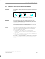
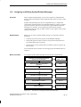
Requirements
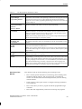
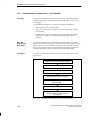
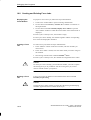
Before you can enter a connection in the connection table, you must have
done the following:
S Created a project
S Assigned parameters to a subnet
S Configured at least two programmable modules (CPU/function module)
in the project and connected them in a network (between which you want
to set up communication connections)
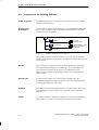
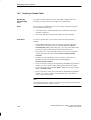
Opening the
Connection Table
You must have opened your project and have opened the station containing
the module for which you want to create the connection table.
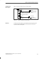
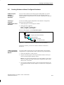
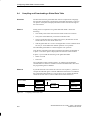
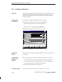
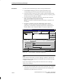
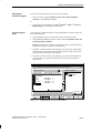
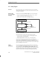
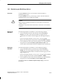
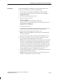
To open a connection table, follow the steps outlined below:
1. Double-click on the programmable module.
2. Select the “Connections” object.
3. Double-click the object or select the menu command Edit " Open
Object.
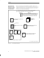
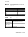
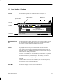
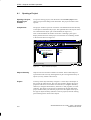
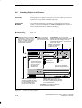
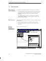
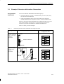
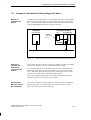
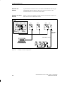
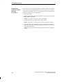
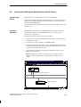
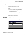
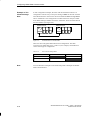
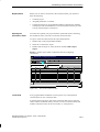
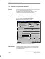
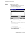
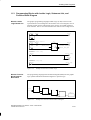
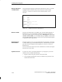
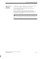
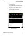
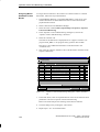
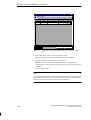
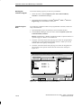
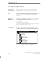
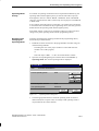
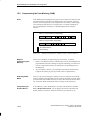
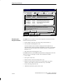
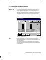
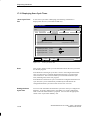
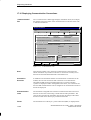
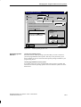
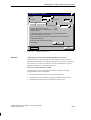
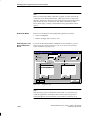
Result: A window opens which contains the table for configuring
connections.
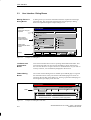
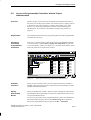
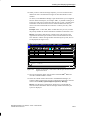
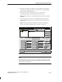
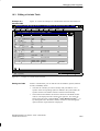
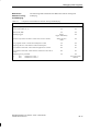
CPU414-2DP - Configuring Connections
Connection Table
Edit
Insert
Station:
SIMATIC 400-Station(2)
Local
ID (hex.)
Partner
ID (hex.)
1
2
4
5
Local Node
Help
View
Module:
CPU414-2DP(1)
Partner
Type
SIMATIC 400-Station(3)/CPU412-1(1)
SIMATIC 400-Station(3)/CPU416-1(1)
S7 Connection.
S7 Connection.
Row: 1 – Loc. ID:1
Ready
Figure 10-2
PLC
Active
Send Op. Mode
Connection Setup Messages
Yes
No
Yes
No
Sel. 1 of 2
View of the Connection Table
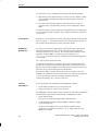
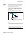
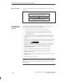
Every programmable module that can be a partner in a communication
connection has its own connection table.
In the list boxes in the upper part of the connection table screen, select the
station and the module for which you want to create a connection table (this
module is then known also as the “local node” or “local partner”).
Standard Software for S7 and M7 – STEP 7 User Manual
C79000-G7076-C552-01
10-3