1
GE Fanuc Automation
Programmable Control Products
Genius™ Modular Redundancy
Flexible Triple Modular Redundant (TMR) System
Technical Product Overview
GFT-177A
February 1998
GFL-002
Warnings, Cautions, and Notes
as Used in this Publication
Warning
Warning notices are used in this publication to emphasize that hazardous voltages,
currents, temperatures, or other conditions that could cause personal injury exist in this
equipment or may be associated with its use.
In situations where inattention could cause either personal injury or damage to equipment,
a Warning notice is used.
Caution
Caution notices are used where equipment might be damaged if care is not taken.
Note
Notes merely call attention to information that is especially significant to understanding and
operating the equipment.
This document is based on information available at the time of its publication. While efforts
have been made to be accurate, the information contained herein does not purport to cover all
details or variations in hardware or software, nor to provide or every possible contingency in
connection with installation, operation, or maintenance. Features may be described herein which
are not present in all hardware and software systems. GE Fanuc Automation assumes no
obligation of notice to holders of this document with respect to changes subsequently made.
GE Fanuc Automation makes no representation or warranty, expressed, implied, or statutory
with respect to, and assumes no responsibility for the accuracy, completeness, sufficiency, or
usefulness of the information contained herein. No warranties of merchantability or fitness for
purpose shall apply.
The following are trademarks of GE Fanuc Automation North America, Inc.
Alarm Master
CIMPLICITY
CIMPLICITY Control
CIMPLICITY PowerTRAC
CIMPLICITY 90–ADS
CIMSTAR
Field Control
GEnet
Genius
Genius PowerTRAC
Helpmate
Logicmaster
Modelmaster
PowerMotion
ProLoop
PROMACRO
Series Five
Series 90
Series One
Series Six
Series Three
VuMaster
Workmaster
©Copyright 1995-1998 GE Fanuc Automation North America, Inc.
All Rights Reserved.
Contents
Section 1
Introduction.................................................................................
1-1
Section 2
Operation ....................................................................................
2-1
Section 3
GMR System Architectures .........................................................
3-1
Section 4
Product Specifications .................................................................
4-1
Section 5
Configuring & Programming a GMR System...............................
5-1
Section 6
Communications..........................................................................
6-1
Appendix A
Memory Allocation......................................................................
A-1
Appendix B
Estimating Scan Time..................................................................
B-1
Appendix C
Computer Requirements for Configuration & Programming .........
C-1
Appendix D
GMR System Glossary................................................................
D-1
iii
Section
Introduction
1
T
M
R
G M R
TM
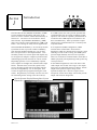
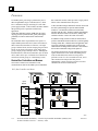
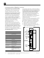
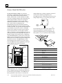
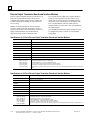
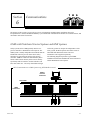
The GE Fanuc Genius Modular Redundancy (GMR)
system combines the flexibility and power of the
Series 90-70 PLC with the advanced functionality of
Genius I/O. The result: an excellent PLC-based,
fault-tolerant, Triple-Modular Redundancy (TMR)
choice for Critical Control Applications. GMR is GE
Fanuc’s sole offering for safety-critical applications.
In a GMR system, the CPUs provide optional data
synchronization only at startup, not during normal
operation. The need for repeated synchronization is
avoided because GMR inputs are broadcast to all
PLCs simultaneously. Other systems that require
ongoing CPU synchronization risk a common point
of system failure.
Genius Modular Redundancy is an extremely flexible
system that is able to provide variable redundancy
from the input modules through one, two or three
PLC CPU processors to the output modules. This
flexibility means less-critical inputs and outputs may
be configured for simplex or duplex operation while
maintaining triplicated elements for critical control.
In its triplicated (TMR) configuration, GMR
includes three isolated PLCs and extensive
diagnostics which are integrated into a single system.
Utilizing two-out-of-three voting, the GMR system
provides high reliability and error-free operation.
There are no hardware common failure modes due to
GMR’s physically uncoupled design and separate leg
circuit protection.
Depending upon the level of redundancy required,
sensor signals are brought into isolated Genius input
blocks. Isolated CPUs, located in separate racks,
receive the input signals from each Genius I/O bus.
The CPUs independently vote on the inputs, then
execute the application program utilizing the voted
results. Programs may be initially stored to one CPU
for monitoring before storing to the other CPU(s).
In the TMR configuration, each of the three CPUs
sends output state results of the logic to the output
subsystem via triplicated Genius I/O busses. Genius
output blocks perform output voting on the
triplicated output data. Discrete output circuits
incorporate current and voltage sensors that provide
output and load state diagnostics.
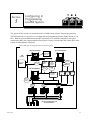
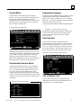
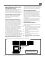
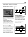
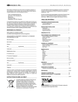
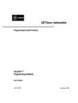
Typical Operator Display Showing Basic System
Components
GFT-177A
1-1
1
GMR identifies system faults, compensates for them
automatically, and allows repair or replacement without
interrupting system operations. Faults are handled by a
software alarm processor function that time-stamps and
logs I/O and system faults in two diagnostic tables that
can be displayed by the programmer or uploaded to a host
computer or other coprocessor.
Each PLC executes continuous diagnostics to detect overt and
covert failures, reducing mean time to repair (MTTR) and
generating automatic fault reports for maintenance or
operations personnel. This fault information is readily available
to the application program, making it possible to take
appropriate control action and alerting maintenance personnel.
Memory errors are detected via parity or checksum, along with
data and address line testing.
Genius I/O, with its distributed design and technology,
allows the I/O to monitor the actions of other intelligent
devices in the system and provide automatic diagnostics
without long wiring runs. Genius I/O accommodates both
local and remote installation requirements and can reduce
installation costs up to 50 percent.
Special Features of a GMR System
In addition to the normal features of typical TMR
systems, such as fault tolerance, comprehensive
diagnostics, remote I/O, online module repair, and high
reliability and availability, GMR provides these benefits:
n
n
n
n
n
n
Application flexibility. Configurable per-point
redundancy makes it possible to customize system
hardware to specific application requirements,
thereby saving money.
Genius I/O speeds startup and eliminates long wire
runs, saving time and money.
Elimination of fuses. Temporary shorts are electronically
cleared, reducing Mean Time To Repair (MTTR)
Fault identification to point level, further reducing
MTTR. Ability to stage and debug input and output
circuitry before CPU installation using a Hand-held
Monitor.
Readily available modules through worldwide
distribution channels.
Software driven and self-documenting configuration.
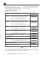
System Programming and Configuration
System configuration and programming are done
using software that installs on an IBM ®-PC or
1-2
compatible computer. Configuration and programming
can be done with the programming computer either online
or offline from the PLC.
The software architecture provides a structured platform
upon which to build application programs. An application
program may be built of many smaller program blocks
each related to a specific machine or process function.
This approach makes it easier to isolate and associate
control logic with machine and process functions.
GMR is shipped as a complete package providing all
safety system functions such as voting, diagnostics, and
startup control. A programmer macro allows all three
PLCs to appear as one for the purpose of downloading
and verification of the application program, saving time
and increasing accuracy.
Communications
A variety of communications options make it possible to
interface the GMR system to Distributed Control Systems
(DCS), operator interfaces or workstations, host computers,
and other devices which communicate using serial
communications, either RTU MODBUS® or GE Fanuc
protocols, Ethernet TCP/IP, or GE Fanuc’s Genius LAN.
Quality is Built In
GE Fanuc has been awarded ISO 9001 certification,
assuring built-in product quality. GMR products are built
in our award-winning Charlottesville, Virginia
manufacturing facility.
GMR is based on two thoroughly field-tested product
families: the Series 90-70 PLC and the Genius I/O
system. Both have demonstrated mean time between
failure (MTBF) statistics that allow system designers to
easily achieve the safety integrity level (SIL) required in
critical applications. In addition, they are both approved
for hazardous location, Class I, Division II installation.
TÜV has certified GMR for classification to these
requirements: triplex Class 5, duplex Class 4 and 5
according to the DIN V19250/DIN V VDE 081 standards.
Field data has been accumulated and submitted for Class 6
type approval, anticipated by the end of 1997. For
information about using the GMR system in a TÜV
approved safety critical installation, refer to information in
the GMR User’s Manual (GFK-1277).
Genius® Modular Redundancy Flexible Triple Modular Redundant (TMR) System
Technical Product Overview – February 1998
GFT-177A
1
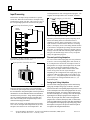
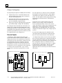
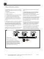
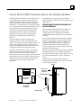
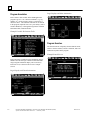
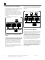
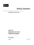
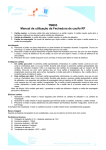
GMR Applications
The GMR input subsystem, PLC subsystem, and output subsystem combine to provide a high-availability, highreliability system.
PLC Subsystem
PLC A
PLC B
ABC
PLC C
ABC
ABC
Load
A
B
No redundancy
or Hot Standby
or Duplex
Input Group
C
2-Block (T)
Fault Tolerant
Output Group
(HighAvailability)
Typical uses of Genius Modular Redundancy technology
are applications that require operation on demand—high
system availability. These applications include equipment
protection, environmental release protection, and
safety-critical protection systems. For details of the
following typical applications of the GE Fanuc Series
90-70 GMR system technology, please contact your local
GE Fanuc distributor or sales representative.
Emergency Shutdown
The GMR system was specifically designed, tested, and
certified to provide redundancy in both CPU and I/O
subsystems, together with the latent fault diagnostic
coverage required for Emergency Shutdown applications
in refining, chemical manufacturing, and other
continuous/batch operation environments.
Functions that cannot be implemented in traditional relay,
DCS, or PLC-based systems are standard features of
GMR. Typical factors that contribute to its reputation for
operation on demand are High Availability (99.999%),
fault coverage that extends to the field device, elimination
of nuisance trips, and fail safe/fault tolerant design.
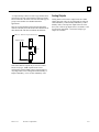
Environmental Protection Systems
Environmental Protection systems are becoming extremely
important in many processing facilities. Uncontrolled events in
chemical production centers can lead to release of toxic
substances into the environment, exposing plant personnel and
adjacent communities to materials now controlled by OSHA.
By monitoring critical variables on reactors, vapor
recovery, and other potentially volatile process units,
GMR can react to bring the unit back to a controlled
GFT-177A
Section 1 Introduction
A
A
Load
2-Block (I)
Fail-safe
Output Group
Shutdown
B
Load
C
D
4-Block (H)
Output
Group
state, eliminating the unwanted activation of other levels
of mitigation such as mechanical pressure-relief devices.
Boiler/Burner Management Systems
If a process boiler stops operating reliably, other parts of
the system are soon affected, leading to loss of both
quality and profits. With the fail-safe and fault-tolerant
GMR system, operations such as purge sequencing, fuel
control, burner ignition, and flame safety can also be
cost-effectively integrated into a single system-meeting
even the most stringent NFPA requirements.
Fire and Gas Detection Systems
Fire and Gas Detection systems require many of the same
high-integrity considerations as Emergency Shutdown (ESD)
applications. However, special design strategies must be
integrated in a Fire and Gas Detection system for monitoring
the field wiring of de-energized control devices and other
functions specific to “energize-to-trip” systems.
GE Fanuc Genius I/O blocks are easily configured to
meet these special application requirements. They can be
certified by leading specification underwriters. In
addition, reduction in spare parts costs can be achieved
through commonality of component requirements for
ESD and Fire & Gas systems, and through the availability
of more than 250 stocking distributors around the globe.
On-line Replacement of Modules
The reliability of GE Fanuc Series 90-70 products has
been field-proven by millions of hours of operation. If a
GMR system component should ever need repair, the
faulty module can be replaced online. Process protection
continues without interruption.
1-3
Section
T M
Operation
R
*05
2
TM
The purpose of this section is to explain how a GMR
system operates—how field inputs are gathered, stored,
and processed, how field outputs are generated, how
voting occurs, and how the extensive diagnostics
capabilities of a GMR system assure maximum I/O data
integrity.
Genius Modular Redundancy is an extremely flexible
system that is able to provide variable redundancy from
the input modules through one to three PLC CPU
processors to the output modules.
Input data is gathered from field input devices wired to
groups of one to three Genius discrete or analog blocks,
or Field Control analog input modules. Each input may
be simplex (single), duplex (double) or triplex (triple)
depending on the needs of the application.
Each Genius or Field Control device transmits input data
once each scan on a Genius bus. Because these devices
broadcast their input data, the same inputs are available
to all PLCs on the bus.
Depending on the redundancy needs of the application,
there may be one, two, or three PLCs in the GMR
system. Each PLC CPU votes on the input data it has
received before each execution of the application
program.
CPUs run asynchronously from each other and do not
share their I/O data, which eliminates the possibility of
one CPU corrupting input data memory in another CPU.
This feature reduces overall system components, and
prevents a common mode single point failure. Any input
voting discrepancies are reported to the built-in PLC
Fault Table in each PLC.
Each CPU executes the same application program,
processing the input data and creating new output data.
Each bus scan, each PLC sends output data to groups of
Genius I/O blocks that control field output devices.
The intelligent Genius output block groups perform
output voting. The manner of voting is configurable for
the application. Because output voting is performed by
the block groups at the point of control, output data
discrepancies are caught by the voting process.
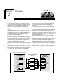
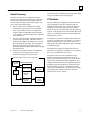
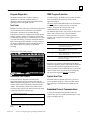
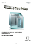
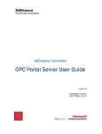
Overview of GMR System Operation
Single, Dual, or Triple
Voted Inputs
Field Input
1
Input
Single, Dual, or Triple
CPUs
Logic
A
2oo3 Voted Outputs
Simplex or
Fault Tolerant
Output
Output
Field Input
2
Field Input
3
Input
Input
Logic
B
Logic
C
Output
Field
Output
Output
a45497
GFT-177A
2-1
2
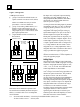
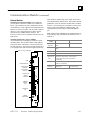
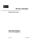
Input Subsystem
A GMR Input sub-system is
A group of 2 or 3 discrete GENIUS blocks (16 or
32 points each with 1 circuit reserved for autotest)
connected to redundant GENIUS lans. Either
common or redundant sensors may be used as
represented in the next two illustrations.
A group of 2 or 3 analog GENIUS blocks (2 or 6
channels) or Field Control modules (4, 8, or 16
channels) connected to redundant GENIUS lans.
Voltage inputs may use a common sensor; current
inputs requires separate sensors.
A single GENIUS or Field Control device (not
safety-related).
■
■
■
Two-block Groups
Bus A & B
or B & C
or C & D
Duplex Sensors
Single Sensor
Each input can be configured for Input Autotesting,
default state, and Voting Adaptation mode. The
Voting Adaptation method determines how the PLC
will perform voting when fewer than three input
signals are present in a group.
All voting for discrete and analog inputs is performed
independently at each PLC. For a two- or three-block
input group, the CPU performs a 2-out of 3 vote on
corresponding inputs. Depending on the
configuration of the input group, input voting may
adapt from three inputs to two inputs to one input or
from three inputs to two inputs to the configured
Default State. When three inputs are present the vote
is a simple majority vote. If only two inputs are present
the PLC uses the point’s configured “duplex” state as
the third input and performs a majority vote. If only
one input is present and the circuit is configured for 3,
2, 1, 0 voting adaptation, the single input is used as
the voted input value. However, if the circuit is
configured for 3, 2, 0 voting adaptation the circuit’s
configured default value is used instead. The result of
voting is provided to the application program.
Single Genius input blocks of any type can be
connected to any Genius bus. The actual input value is
used by the application program.
Analog Inputs
Three-block Groups
Bus A
Bus B Bus C
Triple Sensors
Bus A
Bus B Bus C
Single Sensor
Discrete Inputs
Each Genius block is attached to a separate Genius
bus. Each block independently broadcasts its inputs to
all PLCs, so each PLC CPU receives an independent
copy of all inputs.
2-2
Genius analog blocks and Field Control analog input
modules can be used in GMR input groups in the input
subsystem. Analog input blocks can support 0 to 10V,
+/-10V, +/-5V, 0 to 5V and 4ma to 20ma. RTD and
thermocouple modules are also available.
Analog inputs are handled very much like discrete
inputs. Groups of one to three analog input blocks are
connected to separate Genius busses. They broadcast
their inputs to all PLCs. The PLCs select the
mid-value from among the three corresponding inputs.
Depending on the configuration of the input group,
input voting may adapt from three inputs to two inputs
to one input, or from three inputs to two inputs to the
configured Default Value. The result of the voting is
provided for use by the application program.
The ability of Genius Analog blocks and Field Control
Analog Input modules to convert raw data to
engineering units and directly drive discrete preset
alarm limit points reduces the complexity of software
at the CPU and increases system reliability.
Genius® Modular Redundancy Flexible Triple Modular Redundant (TMR) System
Technical Product Overview – February 1998
GFT-177A
2
Input Diagnostics
The GMR input subsystem provides extensive diagnostic
capabilities through:
■
■
■
Genius diagnostics.
Input Discrepancy Reporting flags any input which
is not in agreement with the majority vote.
Input Autotest determines the ability of each input to
attain the safe state (opposite of its normal state) and
checks for channel-to-channel shorts.
Genius Diagnostics. Genius devices provide extensive
diagnostics protection.
16-circuit DC Sink/Source blocks detect line faults on
tristate inputs (“supervised inputs”). For blocks that are
configured to be in GMR mode, this diagnostic detects
short circuit faults on the field wiring.
On blocks set up for autotesting, power to the input
device is provided by Power Feed Outputs from the
blocks in the Input Group, as illustrated below. (This
output occupies one of the block’s I/O circuits, leaving
either 15 or 31 circuits available for use with input
devices, depending on the block type.) On a configurable
time interval, Input Autotest pulses the Power Feed
Output to Off (this does not change the input reported to
the application). If an input does not turn Off during the
Autotest period, the CPU places a message in the I/O
Fault Table. Off inputs are also tested to ensure that the
blocks’ input circuits can detect the On state.
Input-to-input shorts are also detected.
Input Autotest
TRIPLICATED
BUS
Some analog Input devices allow embedded detection of
open wire and other faults.
Genius blocks identify fault type and exact location to
the point level, and automatically provide that
information to the PLC fault tables. The information is
also available to the application program. This level of
precision in the diagnostics makes it possible to perform
specific repairs without disrupting other elements of the
system unnecessarily.
Input Autotest. The GMR Input Autotest feature
accommodates normally-closed and normally-open
devices with the devices in either state. Input Autotest
detects any failure associated with an input that would
result in a failure to respond. It does not cause spurious
inputs.
Input Autotesting is configurable on a circuit-by-circuit
basis for discrete GMR input circuits.
GFT-177A
Section 2 Operation
*
*
*
*POWER FEED
OUTPUT CHANNELS
a45496
2-3
2
Processors
In a GMR system, processing is performed by one to
three Programmable Logic Controllers (PLCs). Each
PLC is modular in design, consisting of a rack with a
power supply module, a CPU module, and other modules
that perform specific operations needed for the
application.
Unlike other triplicated systems, GMR does not require
ongoing processor synchronization, greatly reducing the
probability of software and hardware common-mode
failures.
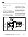
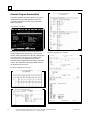
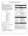
The illustration below represents the basic parts of a
sample GMR system--three PLCs, three Genius busses,
three Genius Bus Controllers in each PLC, one input
group of Genius blocks, and one output group of Genius
blocks. In an actual system, there can be many input
groups, output groups, and triplex busses. Although the
illustration shows each block connected to just one field
device, there can be up to 32 field devices connected to
each block or block group (31 if autotesting is used).
Genius Bus Controllers and Busses
One to three Genius busses transmit I/O and
communications data for the GMR system. Redundant
Bus Controllers and bus cables prevents a single point of
failure in the communications subsystem.
A Bus Controller manages data transfer between its bus and
the CPU by maintaining two separate on-board RAM
memories. One interfaces with the bus and the other
interfaces with the CPU. The Bus Controller automatically
transfers data between these two memories, making data
available to the bus or to the CPU when it is needed.
In addition to being used for I/O data, the Genius busses
provide communications between the PLCs, which regularly
exchange status data. A limited amount of application data
can also be exchanged. Separate busses can be used for
additional data exchanges between the PLCs and with host
devices that communicate using Genius protocol.
The Genius Bus Protocol provides inherent protection
against transmission errors. Each transmitting device
sends each bit three times. Each receiving device
performs a 2-out of 3 vote on each bit received, and a
CRC checksum on each packet This process
automatically corrects any bits received in error and
eliminates the need for retransmission.
PLCs, Bus Controllers and Busses
C
P
U
Input
Device
B
U
S
B
U
S
B
U
S
C
O
N
T
R
O
L
L
E
R
C
O
N
T
R
O
L
L
E
R
C
O
N
T
R
O
L
L
E
R
C
P
U
B
U
S
B
U
S
B
U
S
C
O
N
T
R
O
L
L
E
R
C
O
N
T
R
O
L
L
E
R
C
O
N
T
R
O
L
L
E
R
Geni
C
P
U
B
U
S
B
U
S
B
U
S
C
O
N
T
R
O
L
L
E
R
C
O
N
T
R
O
L
L
E
R
C
O
N
T
R
O
L
L
E
R
Geni
LOAD
46629
2-4
Genius® Modular Redundancy Flexible Triple Modular Redundant (TMR) System
Technical Product Overview – February 1998
GFT-177A
2
Synchronization
PLC Diagnostics
Unlike other triplicated systems, GMR does not require
ongoing processor synchronization, greatly reducing the
probability of software and hardware common mode
failures. In a GMR system, each PLC typically runs the same
Each PLC executes continuous diagnostics to detect
internal overt and covert failures. Memory errors are
detected via parity or checksum.
application program. Application program data is optionally
synchronized among the PLCs during system startup. It is also
optionally synchronized whenever one or more PLCs is taken
offline and then restarted.
Initial System Program Synchronization
Upon initialization of the application program, each PLC
runs a startup diagnostic, checks the status of all system
components and provides an orderly, controlled startup. If
any errors occur, they are logged into a fault table in the
PLC and made available to the application program
through diagnostic status bits. Initialization errors may or
may not stop the PLC; this is determined by the GMR
configuration set up for the application.
Partial Restart System Program Initialization
If one or more CPUs are taken offline while the system
continues to operate, a “warm start” is automatically initiated
when the offline CPU(s) are re-introduced. This optionally
allows data to synchronize with the other CPU(s), verifies that
system operation is correct, and determines the application
logic is equal in the PLCs. Optional data synchronization
eliminates potential discrepant control commands being issued
between individual processors that are joining the online
operational system.
Inputs and Outputs
Genius and Field Control devices broadcast the status of
all inputs simultaneously to all online CPUs. Each CPU
independently solves the application logic and transmits
the resulting commanded output states independently to
the output modules.
Global Data
During GMR system operation, the PLCs use Global Data to
automatically exchange eight registers of system status and
diagnostic data. This data is directly available for the
application program in each PLC. Global Data transfer
occurs on two of the fault-tolerant GMR busses, so each PLC
actually receives two sets of Global Data from each of the
other PLCs. The use of two busses provides redundant
operation in case a bus or bus controller is not available.
In some applications, it may also be desirable to regularly
exchange additional application data between the PLCs.
Up to 56 registers of application data can be exchanged
on the redundant GMR busses using Global Data.
GFT-177A
Section 2 Operation
Each CPU receives the other CPUs’ status as part of the
Global Data exchange. This status information is
available for the diagnostic fault table, system default
operation, and application program. Each PLC can
monitor the actions of the two other PLCs to detect voting
discrepancies. Each PLC also compares its application
program checksum with those of the other PLCs and can
be shut down if it is in discrepancy with the other two. A
PLC that goes off-line is reported by the other two.
The application program can make use of additional
diagnostics mechanisms provided by the Series 90-70 PLC
and special diagnostics features of the GMR system software.
n
System Status References.
n
Fault and Alarm contacts.
n
GMR Status and Control references.
System Status References are pre-defined references
that can be included in the application program to check
for specific fault-related conditions. Additional system
status references indicate when the fault table has a new
entry, has any entry, or is full.
Fault and Alarm Contacts: The GMR system software
can optionally utilize the Fault and Alarm contacts
capability of the Series 90-70 PLC to make fault and
alarm information available to the application program.
Fault and No Fault contacts can be used to detect fault or
lack of fault conditions on a discrete or analog point.
Fault and No Fault contacts can also be programmed with
the Series 90-70’s built-in fault-locating references.
Fault-locating references identify faults associated with
the system hardware to the point level. Alarm contacts
can be used to indicate when an analog value has reached
an assigned alarm limit.
GMR Status and Control References. The GMR system
includes many status and control bits that can be used in an
application program. Status bits provide information about
GMR operations such as: system fault at startup, output
discrepancy, autotest in progress, I/O reset in progress, PLC
is online, I/O shutdown is activated, PLC is OK. These
references can be read as needed by the application program.
Control bits can be used to command system operations
such as: clearing fault tables, initiating or inhibiting
autotesting, and canceling I/O shutdown.
2-5
2
Input Processing
Voted Inputs data is used in the application program. The
original, unvoted input data is also available, if needed.
Each block in an Input Group is attached to a separate
Genius bus. When the Genius blocks in the Input Group
broadcast their inputs, each PLC CPU receives a copy of
the corresponding inputs from each block in the group.
Input Table Mapping in Each CPU
GMR
Inputs
VOTED
INPUTS
A
Input Group Broadcasting Inputs
B
Input
Device
Bus A
Bus B
Bus C
INPUT
VOTING
LOGIC
C
a45492
Genius
Input Discrepancy Reporting
Genius
Genius
46630
In each PLC, the Bus Controller on each bus receives the
input data and provides it to the CPU.
Inputs from Bus Controllers to a CPU
C
P
U
Bus A
Bus B
Discrete Input Voting Adaptation
For a two or three block input group, the CPU performs a
2-out of 3 vote on corresponding bits in each section (A,
B, C) and places the result in the Voted input section of
the input table. For single Genius input block, the actual
input value is used by the application program. If a
discrepancy fault, Input Autotest fault or Genius fault
occurs on any point, the CPU rejects that input.
Depending on the configuration of the input group, input
voting may adapt from three inputs to two inputs to one
input (a 3, 2, 1, 0 degradation path) or from three inputs
to two inputs to the configured Default State (a 3, 2, 0
degradation path).
Analog Input Voting Adaptation
Bus C
46631
Each CPU places the input data it receives from the Bus
Controllers in separate input tables, shown as A, B, and C in
the next illustration. The parallel update of these input tables
eliminates the need for additional I/O data communication
networks between processors – along with the possibility of
one CPU corrupting input data memory in another CPU.
This reduces overall system components and prevents a
common-mode single point failure.
Before each execution of the application program each
CPU votes on the input data in input tables A, B, and C
and places the results into its Voted Inputs table. The
2-6
Each PLC performs Input Discrepancy Reporting on all
discrete and analog blocks for which the feature is
enabled. For discrete inputs, a discrepancy exists if one
input remains at variance with the other two. For analog
inputs, a discrepancy exists if one analog channel deviates
by more than a configurable percentage from the selected
mid-value. If a discrepancy is detected, the PLC places a
message in the I/O fault table indicating which input does
not agree. The fault message can be seen by an operator
and by the application program.
For a three-block analog input group or Field Control analog
input group, the Input Voting Logic in each PLC selects the
mid-value from three corresponding inputs and places the result
in the Voted Input section of the Analog Input Table for use by
the application program. For a group with two analog inputs,
the CPU uses the high, low, or average value of the two inputs,
depending on how that input group has been configured. If
there is only one input value, that is used for the application
program value. If a failure (discrepancy fault, or Genius fault)
occurs, the GMR software rejects the faulty data. Depending on
the configuration of the input group, input voting may go from
three inputs to two inputs to one input, or from three inputs to
two inputs to the configured default value.
Genius® Modular Redundancy Flexible Triple Modular Redundant (TMR) System
Technical Product Overview – February 1998
GFT-177A
2
Output Processing
The Genius blocks in GMR output groups perform output
voting, as described on the following pages.
Each CPU executes the same application program,
processing the input data and creating new output data.
The PLC uses separate areas of the Output Table for
non-voted discrete outputs, fault-tolerant outputs, and
copies of the fault-tolerant outputs.
n
n
n
Data for blocks that are included in the GMR
configuration is placed at the start of the Output
Table. In the illustration below, the application
program outputs for redundant blocks are labeled
“logic outputs”. This data is followed by outputs for
non-voted blocks.
The CPU copies these logic outputs into the bottom
portion of the Output Table. This data, shown as
Fault-tolerant Outputs in the illustration, is used for
physical outputs for the blocks. This separation of
physical outputs from logical outputs prevents
disruption of outputs such as latches and seal circuits
during autotesting.
Each bus scan, the Bus Controllers automatically
send the non-voted outputs plus the copied
fault-tolerant outputs to the Genius blocks.
Discrete Output Processing in Each CPU
Application
Program
Discrete Output Table
Available for
Simplex Outputs
Non-voted
Outputs
GMR
Logic
I/O Shutdown
When the GMR system diagnoses a discrete I/O fault, it
logs the appropriate faults in its fault tables and sets
appropriate fault contacts. For certain types of discrete
I/O faults, the system optionally allows a predefined
amount of time for the problem that caused the fault to be
repaired. If the problem is not rectified within this period
of time, an I/O Shutdown of the I/O corresponding to the
affected block(s) occurs.
I/O Shutdown is defined as setting the affected I/O to its
safe state. For outputs, this is the Off state. For discrete
inputs, the shutdown state is the “default” state for an
input group in the GMR configuration. This is selectable
for each input group.
The application program can monitor status bits to be
made aware of a pending I/O Shutdown, or to completely
prevent an I/O Shutdown from occurring.
The period of time before an I/O Shutdown occurs
depends on the autotest interval which is set for the
system. The initial autotest interval is set by the autotest
interval value selected in the GMR configuration. The
configured autotest interval can be adjusted in each CPU
through the application program by varying the value in
the autotest interval register. For example, the system
allows a total maximum time of 24 hours between a fault
occurring and the resultant I/O shut down when the
autotest interval is set to 8 hours.
Reserved
memory
Fault-tolerant
Outputs
Fault-tolerant
Output
Devices
46632
GFT-177A
Section 2 Operation
2-7
2
Output Subsystem
The output subsystem portion of a GMR system can include:
Output Groups of two or four Sink and Source DC
discrete Genius blocks wired to up to 32 actuators
and other field output devices
Individual Sink and Source DC discrete Genius
blocks wired to up to 32 field output devices, for
processor redundancy and pulse testing.
Other types of discrete and analog blocks, which can
provide Hot Standby or Duplex PLC Redundancy.
n
n
n
The intelligent Genius Sink and Source DC blocks store
multiple sets of outputs in internal output tables. These
block groups perform the voting. The manner of voting is
configurable for the application. Because output voting is
performed by the blocks at the point of control, bus errors
are compensated for by the voting process.
Discrete Outputs
A standard “H” pattern output Genius block group
provides fault-tolerant control for discrete outputs. An
output group consists of two parallel Source-type blocks
connected to one side of the actuator or other device and
two parallel Sink-type blocks connected to other side.
The diagram below represents connections between a
triplicated bus, a group of 16-circuit Genius blocks and
one load device. Up to 16 field devices can be connected
to a group of four 16-circuit blocks. Up to 32 field
devices can be connected to a group of four 32-circuit
blocks.
4-Block Discrete Output Group
For each output device, each PLC sends a commanded
state output to each of the four blocks. Under ordinary
circumstances, the outputs received from all the PLCs
match. For each output, the block group performs voting
on the data received from the PLCs to determine the
output state.
If the blocks receive outputs from three PLCs, they
perform 2 out of 3 voting. If only two outputs are
received, the blocks do either 1 out of 2 or 2 out of 2
voting. The method of voting is easily configured for each
output group. If only a single output is received, the
outputs follow the commanded state. The system can be
configured to default the outputs if only a single output is
received.
In a four-block output group, the combination of the
voted output states of all four blocks controls the load,
due to the electrical characteristics of the four blocks.
“T” Output Groups consist of of two source-type (shown
here) or sink type Genius blocks, connected in parallel on
one side of the load. The other side of the load is tied to
ground. when two source blocks have been configured. In
the T configuration where two sink blocks have been
used, the other side of the load is tied to 24V. A 2-Block
T Output group is “fault tolerant”. This type of group
might be used in high-availability or fire-and-gas
applications where it is necessary to be able to turn ON a
critical load.
2-Block “T” Discrete Output Group
+24 Volts
Separate Busses
Source
Source
TRIPLICATED
BUS
Source
Source
FIELD
LOAD
LOAD
Sink
Sink
0 Volts
0 Volts
2-8
Genius® Modular Redundancy Flexible Triple Modular Redundant (TMR) System
Technical Product Overview – February 1998
GFT-177A
2
“I” Output Groups consist of a source-type Genius block
connected to one side of the load and a sink-type Genius
block connected to the other side of the load. This type of
group is most suitable for redundant shutdown
applications
This type of group might be used in fail-safe applications
where it is necessary to be able to turn OFF a critical load. If
either block faults. The other can still turn the load OFF.
Analog Outputs
Analog blocks can be used as single blocks in a GMR
output subsystem. They can be configured for either No
CPU Redundancy or Hot Standby Redundancy. In Hot
Standby mode, a block prefers outputs from one of the
PLCs, but it will accept outputs from a second PLC if the
first becomes unavailable. Current and voltage type
outputs are available.
2-Block “I” Discrete Output Block Group
Separate Busses
Source
LOAD
Sink
Non-critical discrete outputs may be wired to Genius
blocks of any type. GMR capable blocks can be
configured to perform GMR voting as described above.
Any single block can be configured for Hot Standby or
Duplex redundancy, or for no CPU redundancy at all.
GFT-177A
Section 2 Operation
2-9
2
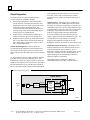
Output Diagnostics
Circuit diagnostic message which is received by each
PLC CPU. In the event of a transient short, normal
operation can be restored by clearing the fault in any of
the PLCs.
In a GMR system, the output subsystem provides
extensive diagnostic capabilities through:
n
n
n
Genius Output Diagnostics, which include Short
Circuit detection, Overtemperature detection, and
Failed Switch detection (which compares the actual
output state with the commanded state). The
16-circuit DC Sink/Source blocks also perform No
Load reporting, which monitors individual outputs
for the presence of a minimum load.
Output Autotest, which determines whether each
output can attain the opposite of its normal state.
Output Discrepancy Reporting, which informs each
PLC of any output which is not the same among all
PLCs. Discrepancy reporting also reports on each
PLC’s online/offline status.
Genius Output Diagnostics. Each I/O point on a
16-point discrete DC Sink/Source block incorporates a
current sensor and a voltage sensor in the smart switch
design. This provides data about output circuitry and load
state.
On 16-point blocks, discrete output circuits are protected
by a short circuit sensor at the switching device. If the
instantaneous current on an output exceeds 20 Amps, the
output turns off within several microseconds. The Genius
block automatically tries to restart the load. If repeated
tries fail, the block turns the output Off and sends a Short
Output Autotest. Each output can be configured for
Output Autotesting. The GMR Output Autotest checks
the ability of each discrete output block to respond to the
commanded output state. Discrete Output Autotest works
on outputs that are either On or Off, with or without load
monitoring. Output Autotest does not cause spurious
faults to be logged and does not affect field output
devices-the Genius blocks still control the physical
outputs. Output Autotest can be inhibited for repair. The
test uses the blocks’ built-in Pulse Test capability.
Single blocks configured for Duplex or No CPU
Redundancy cannot be autotested, but can be pulse-tested.
Output Discrepancy Reporting. If the blocks receive
different outputs for the same load from the PLCs, they
report the discrepancy back to each PLC, where a
discrepancy message is placed in the Fault Tables. At the
same time, a status bit is set. By checking this bit, the
application program can automatically be alerted to
output discrepancies at the blocks.
Output Discrepancy reporting also supplies the
online/offline status of each PLC to the other PLCs.
Genius Output Diagnostics
SMART SWITCH
Genius
Bus
Input Data
COMM
VLSI
IC
MICRO
SWITCH
DRIVE
and
PROCESSOR
Output Data
DIAGNOSTICS
LOGIC
+V
Switch
Drive
Load Current
I
Feedback
Load Voltage
LOAD
Feedback
V
a45495
2-10
Genius® Modular Redundancy Flexible Triple Modular Redundant (TMR) System
Technical Product Overview – February 1998
GFT-177A
Section
3
T M
GMR System
Architectures
R
*05
TM
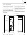
Larger applications can include up to seven Expansion
Racks daisy-chained from the Main Rack of each
GMR PLC. In a system with Expansion Racks, there
must be a Bus Transmitter Module in the Main Rack
and a Bus Receiver Module (BRM) in each Expansion
Rack. The last Expansion Rack can be up to 50 feet
(15 meters) from the Main Rack.
Each Expansion Rack supports up to nine modules,
with one slot used for a BRM. A GMR system with
three PLCs can include up to 24 racks with to 93
Genius Bus Controllers (31 triplicated sets). Some
intelligent modules must be located in the Main Rack.
GMR Bus Controllers can be located in the Main Rack
or in any Expansion Rack.
No spare slots are required in any rack for “spares” or
“hot replacements”. Mechanical keying prevents modules
from being inserted into the wrong location. The
architecture of a GMR system makes it possible to replace
any module while the system continues operating.
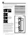
The purpose of this section is to give an overview of the
elements that make up a GMR system, and to describe
different types of GMR systems that can be designed.
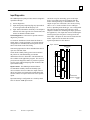
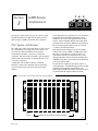
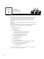
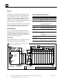
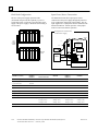
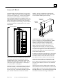
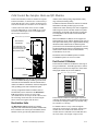
PLC System Architecture
The GMR CPU resides in the Main Rack of a Series 90-70
PLC, immediately to the right of the power supply. The
rest of the slots in the Main Rack can be used for
communication modules, coprocessors, Genius Bus
Controllers, and rack–based I/O modules. Special-purpose
modules and custom modules (as illustrated below in slot
9) can also be included.
A Main Rack with six Bus Controllers can handle
hundreds of single, dual, and triple discrete and analog
I/O points using Genius I/O blocks and Field Control
modules.
Series 90-70 PLC 19-inch Main Rack with Typical Modules
CENTRAL
POWER SUPPLY
PROCESSOR
UNIT
BUS
TRANSMITTER
GENIUS
BUS CONTROLLER
GENIUS
BUS CONTROLLER
GENIUS
BUS CONTROLLER
PROGRAMMABLE COMMUNICATIONS
COPROCESSOR
COPROCESSOR
ETHERNET
CONTROLLER
GE Fanuc
SERIES 90-70
PROGRAMMABLE
CONTROLLER
Power
Supply
1
2
3
4
5
6
7
8
9
Modules can be selected to suit the application
a46600
GFT-177A
3-1
3
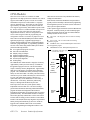
PLC Redundancy Options
For maximum system integrity, two or three PLCs
protect against failure of the PLC CPU or power source,
or even loss of an entire PLC system. The ability to have
processing performed by two or three independent PLCs
is an additional important advantage of GMR.
Redundancy options for the PLC portion of a GMR
system include:
■
■
■
Simplex: one PLC
Duplex: two PLCs
Triplex: three PLCs
Each PLC CPU resides in an independent rack,
eliminating mechanical and electrical common mode
failure. Individual PLC CPU racks may be located up to
7500’ apart (the maximum distance between PLCs
depends on the baud rate selected for the Genius bus that
connects them).
A minimum of two bus controllers per PLC are required
for fault-tolerant inter-processor communications. This
allows the GMR PLCs to exchange initialization data at
startup and exchange up to 64 words of global data
during operation.
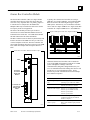
Even when only one PLC is used, triplicated Genius Bus
Controllers and bus cables, along with the ability to have
triplicated inputs and fault tolerant, failsafe voted
outputs, provides significant levels of redundancy.
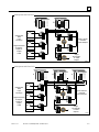
The GMR redundancy options for both inputs and
outputs can be used with one, two, or three GMR PLCs,
as shown by the following illustrations. For clarity, the
illustrations show PLCs without expansion racks and
only a few Genius blocks per bus. In an actual system,
there can be up to eight racks per PLC and 32 devices
(Genius blocks, Bus Controllers, etc) per Genius bus.
GMR System with One PLC
C
P
U
B
U
S
C
O
N
T
R
O
L
L
E
R
B
U
S
C
O
N
T
R
O
L
L
E
R
B
U
S
C
O
N
T
R
O
L
L
E
R
Geniu
Independent
Field
Input
Device(s)
Geniu
Fault Tolerant
Fail Safe
Voted Outputs
LOAD
Geniu
Geniu
Single Nonvoted
or Simplex,
Duplex or
Triplex
Voted
a46601
3-2
Genius® Modular Redundancy Flexible Triple Modular Redundant (TMR) System
Technical Product Overview – February 1998
GFT-177A
3
GMR System with Two PLCs
B
U
S
C
O
N
T
R
O
L
L
E
R
C
P
U
B
U
S
C
O
N
T
R
O
L
L
E
R
B
U
S
C
O
N
T
R
O
L
L
E
R
B
U
S
C
O
N
T
R
O
L
L
E
R
C
P
U
B
U
S
C
O
N
T
R
O
L
L
E
R
B
U
S
C
O
N
T
R
O
L
L
E
R
Geniu
Independent
Field
Input
Device(s)
Geniu
Fault Tolerant
Fail Safe
Voted Outputs
LOAD
Geniu
Geniu
Single Nonvoted
or Simplex,
Duplex or
Triplex
Voted
Single
Hot Standby
or Voted
Outputs
Geniu
LOAD
a46602
GMR System with Three PLCs
B
U
S
C
O
N
T
R
O
L
L
E
R
C
P
U
B
U
S
C
O
N
T
R
O
L
L
E
R
B
U
S
C
O
N
T
R
O
L
L
E
R
C
P
U
B
U
S
C
O
N
T
R
O
L
L
E
R
B
U
S
C
O
N
T
R
O
L
L
E
R
B
U
S
C
O
N
T
R
O
L
L
E
R
B
U
S
C
O
N
T
R
O
L
L
E
R
C
P
U
B
U
S
C
O
N
T
R
O
L
L
E
R
B
U
S
C
O
N
T
R
O
L
L
E
R
Geniu
Geniu
Independent
Field
Input
Device(s)
Geniu
Fault Tolerant
Fail Safe
Voted Outputs
LOAD
Geniu
Geniu
Single Nonvoted
or Simplex,
Duplex or
Triplex
Voted
Geniu
Geniu
Geniu
LOAD
Single
Hot Standby
or Voted
Outputs
a46603
GFT-177A
Section 3 GMR System Architectures
3-3
3
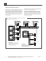
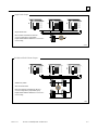
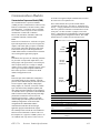
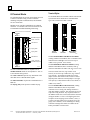
Input Redundancy Options
The flexibility of the GMR system makes it possible to
apply the exact mix of input redundancy options needed
for the application. The use of duplex or triplex sensors
that provide signals to either two or three Genius blocks
or Field Control analog input modules from the same
portion of the monitored process provides maximum
input redundancy.
Redundancy options for input devices in a GMR system
are shown in the following illustrations.
The types of redundant input options shown in these
illustrations are available for both discrete inputs and
analog inputs. Note that analog inputs can use either
Genius or Field Control devices, including inputs from
thermocouples and RTDs.
Three Input Devices Connected to Three Blocks or One Input
Device Connected to Three Blocks
B
U
S
C
O
N
T
R
O
L
L
E
R
C
P
U
Field Device
B
U
S
C
O
N
T
R
O
L
L
E
R
B
U
S
C
O
N
T
R
O
L
L
E
R
C
P
U
B
U
S
C
O
N
T
R
O
L
L
E
R
B
U
S
C
O
N
T
R
O
L
L
E
R
B
U
S
C
O
N
T
R
O
L
L
E
R
B
U
S
C
O
N
T
R
O
L
L
E
R
C
P
U
B
U
S
C
O
N
T
R
O
L
L
E
R
B
U
S
C
O
N
T
R
O
L
L
E
R
Geniu
Field Device
Geniu
Geniu
Geniu
Geniu
Triplex sensors
Discrete, analog, thermocouple, RTD
Separate Genius bus for each block
All PLCs receive all inputs
Geniu
Single sensor
Discrete, analog, thermocouple, RTD
Separate Genius bus for each block
All PLCs receive all inputs
a46604
3-4
Genius® Modular Redundancy Flexible Triple Modular Redundant (TMR) System
Technical Product Overview – February 1998
GFT-177A
3
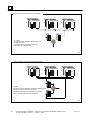
Two Input Devices Connected to Two Genius Blocks or One Input
Device Connected to Two Blocks
B
U
S
C
O
N
T
R
O
L
L
E
R
C
P
U
Field Device
B
U
S
C
O
N
T
R
O
L
L
E
R
B
U
S
C
O
N
T
R
O
L
L
E
R
C
P
U
B
U
S
C
O
N
T
R
O
L
L
E
R
B
U
S
C
O
N
T
R
O
L
L
E
R
C
P
U
B
U
S
C
O
N
T
R
O
L
L
E
R
Geniu
Field Device
Geniu
Geniu
Geniu
Single sensor
Discrete, analog, thermocouple, RTD
Separate Genius bus for each block
All PLCs receive all inputs
Duplex sensors
Discrete, analog, thermocouple, RTD
Separate Genius bus for each block
All PLCs receive all inputs
a46605
One Input Device Connected to Simplex or Non-voted Block
B
U
S
C
O
N
T
R
O
L
L
E
R
C
P
U
Field Device
C
P
U
B
U
S
C
O
N
T
R
O
L
L
E
R
C
P
U
B
U
S
C
O
N
T
R
O
L
L
E
R
Geniu
Simplex or non-voted
Discrete, analog, thermocouple, RTD
All PLCs receive all inputs
a46606
GFT-177A
Section 3 GMR System Architectures
3-5
3
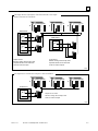
Output Redundancy Options
Output redundancy options can be mixed as appropriate
within the system. Options for output devices in a GMR
system include:
■
■
■
■
■
Single, hot standby outputs.
Single voted outputs.
H–pattern group for fault–tolerant, failsafe outputs.
T–pattern group for fault tolerant outputs.
I–pattern group failsafe for shutdown outputs.
A single block in GMR mode receives outputs from all
CPUs and performs voting (2 out of 3, 2 out of 2, or 1
out of 2).
For Hot Standby redundancy, a load must be connected
to one sink-type or source-type discrete Genius block.
Blocks in Hot Standby mode receive outputs from all
GMR CPUs and use the output data from the CPU with
the Bus Controllers at the highest serial bus address (31,
30, 29) that are currently online.
Output loads that must be both failsafe and fault-tolerant
are connected to a standard “H” pattern group of two
parallel source-type blocks and two parallel sink-type
blocks.
A T-pattern output group can provide fault–tolerant
operation with two parallel sink-type or source-type
blocks. This type of group might be used in
high-availability or fire–and–gas applications where it is
necessary to be able to turn ON a critical load.
An I-pattern output group can provide failsafe operation
with one sink–type and one source-type block wired in
series with a load. This type of group might be used in
failsafe applications where it is necessary to be able to
turn OFF a critical load.
Non-critical outputs can be wired to individual discrete
or analog blocks. Such blocks can be configured for no
redundancy, or for one of the three CPU redundancy
modes: Hot Standby, Duplex or GMR (2 out of 3).
For clarity, the illustrations show only one output load
connected to a single block or to a group of blocks.
However, each block or group of blocks can control
outputs to 16 or 32 loads, depending on the block type.
Single Hot Standby Output
C
P
U
B
U
S
C
O
N
T
R
O
L
L
E
R
B
U
S
C
O
N
T
R
O
L
L
E
R
B
U
S
C
O
N
T
R
O
L
L
E
R
C
P
U
B
U
S
C
O
N
T
R
O
L
L
E
R
B
U
S
C
O
N
T
R
O
L
L
E
R
B
U
S
C
O
N
T
R
O
L
L
E
R
C
P
U
B
U
S
C
O
N
T
R
O
L
L
E
R
B
U
S
C
O
N
T
R
O
L
L
E
R
B
U
S
C
O
N
T
R
O
L
L
E
R
Single Genius block
Block receives command from all PLCs
Geniu
LOAD
LOAD
For Hot Standby redundancy, a load must be
connected to one sink-type or source-type discrete
Genius block. Blocks in Hot Standby mode receive
outputs from all GMR CPUs and use the output data
from the CPU with the Bus Controllers at the highest
serial bus address that are currently online.
a46607
3-6
Genius® Modular Redundancy Flexible Triple Modular Redundant (TMR) System
Technical Product Overview – February 1998
GFT-177A
3
Single Voted Output
C
P
U
B
U
S
C
O
N
T
R
O
L
L
E
R
B
U
S
C
O
N
T
R
O
L
L
E
R
B
U
S
C
O
N
T
R
O
L
L
E
R
C
P
U
B
U
S
C
O
N
T
R
O
L
L
E
R
B
U
S
C
O
N
T
R
O
L
L
E
R
B
U
S
C
O
N
T
R
O
L
L
E
R
C
P
U
B
U
S
C
O
N
T
R
O
L
L
E
R
B
U
S
C
O
N
T
R
O
L
L
E
R
B
U
S
C
O
N
T
R
O
L
L
E
R
Single Genius block
Block receives command from all PLCs
Geniu
LOAD
2 out of 3 voting done by output block
Duplex default selection determines 1 out of 2 or 2
out of 2 voting
a46608
Fail Safe and Fault Tolerant Output
C
P
U
B
U
S
C
O
N
T
R
O
L
L
E
R
B
U
S
C
O
N
T
R
O
L
L
E
R
B
U
S
C
O
N
T
R
O
L
L
E
R
C
P
U
B
U
S
C
O
N
T
R
O
L
L
E
R
B
U
S
C
O
N
T
R
O
L
L
E
R
Geniu
B
U
S
C
O
N
T
R
O
L
L
E
R
C
P
U
B
U
S
C
O
N
T
R
O
L
L
E
R
B
U
S
C
O
N
T
R
O
L
L
E
R
B
U
S
C
O
N
T
R
O
L
L
E
R
Geniu
Standard “H” pattern
Sink and source blocks
Each block receives command from all PLCs
2 out of 3 voting done by output block group
Duplex default selection determines 1 out of 2 or 2
out of 2 voting
LOAD
Geniu
Geniu
a46609
GFT-177A
Section 3 GMR System Architectures
3-7
3
2 Block T-Pattern Group for High Availability
C
P
U
B
U
S
C
O
N
T
R
O
L
L
E
R
B
U
S
C
O
N
T
R
O
L
L
E
R
C
P
U
B
U
S
C
O
N
T
R
O
L
L
E
R
B
U
S
C
O
N
T
R
O
L
L
E
R
SRC
B
U
S
C
O
N
T
R
O
L
L
E
R
B
U
S
C
O
N
T
R
O
L
L
E
R
SRC
Geniu
"T" pattern
Two Source or Two Sink blocks. Blocks must be on
two different busses
Each block receives command from all PLCs
Either block can control the load
C
P
U
Geniu
LOAD
a46634
2 Block, I-Pattern Group for Redundant Shutdown
C
P
U
B
U
S
C
O
N
T
R
O
L
L
E
R
B
U
S
C
O
N
T
R
O
L
L
E
R
C
P
U
B
U
S
C
O
N
T
R
O
L
L
E
R
B
U
S
C
O
N
T
R
O
L
L
E
R
C
P
U
B
U
S
C
O
N
T
R
O
L
L
E
R
B
U
S
C
O
N
T
R
O
L
L
E
R
Geniu
"I" pattern
One Source and One Sink block connected to different busses
Each block receives command from all PLCs
Both blocks must be active to control the load. If either
fails On, turning the other Off turns the load Off
LOAD
Geniu
a46633
3-8
Genius® Modular Redundancy Flexible Triple Modular Redundant (TMR) System
Technical Product Overview – February 1998
GFT-177A
Section
Product
Specifications
4
T
M
R
G M R
TM
The purpose of this section is to describe in detail the Series 90-70 PLC, Genius
I/O, and Field Control I/O products that might be included in a GMR system.
The section begins with a group of lists of components. Each list includes
product catalog numbers and the individual TÜV approval status of each
component.
Following the component listings, you will find information on agency approvals
and standards.
Detailed product information begins on page 4-8, immediately after the listings.
The product descriptions are included under the following headings:
n
n
n
n
n
n
n
n
n
Racks
Power Supply Modules
CPU Modules
Communications Modules
o Communications Coprocessor Module (CMM)
o Programmable Coprocessor Module (PCM)
o Factory LAN Ethernet Controller Module
Bus Transmitter & Bus Receiver Modules
Genius Bus Controller Module
o Genius I/O Network
Genius I/O Blocks
Genius Hand-Held Monitor
o Genius Block GMR Termination Boards and Interface Modules
Field Control Bus Interface Units and I/O Modules
o Field Control Analog Input Modules
o
I/O Terminal Blocks
If you need more information about any of these products, please refer to other GMR,
Series 90-70 and Genius manuals for further details.
GFT-177A
4-1
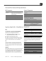
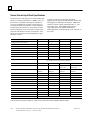
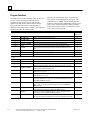
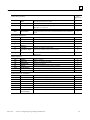
4
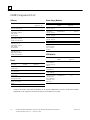
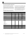
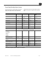
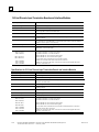
GMR Components List
Software
Power Supply Modules
Description
Catalog Number
TÜV
Approved
Refer
To:
Description
Catalog
Number
GMR System Software for
CPU 788, 789, and 790
IC641SWP715
Yes
n/a
120/240Vac,
125Vdc, 50 Watt
Logicmaster 90-70
Programming Software
w/CD–ROM
Documentation
IC640HWC706
Yes
n/a
Logicmaster 90-70
Programming Software
w/Paper Documentation
IC640HWP706
TCP/IP Ethernet
Logicmaster 90–70
Programming Software
w/CD–ROM
Documentation
IC641SWC713
TCP/IP Ethernet
Logicmaster 90-70
Programming Software
w/Paper Documentation
IC641SWM713
Yes
n/a
n/a
n/a
Catalog
Number
9–slot rear mount
IC697CHS790D
(panel mount)
9–slot front mount (19– IC697CHS791
inch rack mount)
TÜV
Refer To:
Approved
Yes
Page 4-8
*
Page 4-8
5–slot rear mount
(panel mount)
IC697CHS750
*
Page 4-8
17–VME-slot rear
mount (panel mount)
IC697CHS782
*
Page 4-8
17–VME-slot front
mount (19–inch rack
mount)
IC697CHS783
*
Page 4-8
Rack Fan Assembly
IC697ACC721/724
*
-
*
4-2
Refer To:
IC697PWR710
*
Page 4-9
120/240Vac,
125Vdc, 50 Watt
IC697PWR712
*
Page 4-9
115/240Vac,
125Vdc, 100 watt
IC697PWR711
Yes
Page 4-9
115/240Vac,
125Vdc, 100 watt
IC697PWR713
*
Page 4-9
24Vdc, 90 watt
IC697PWR724
*
Page 4-9
48Vdc, 90 Watt
IC697PWR748
*
Page 4-9
Power Supply
Expansion Cable
(For 2–rack P/S
function)
IC697CBL700
*
Page 4-9
CPU Modules
Racks
Description
TÜV
Approved
Description
Catalog
Number
TÜV
Refer To:
Approved
790 GMR CPU
(2048 TMR I/O).
Includes 1 meg. of
memory
IC697CPM790
Yes
Page 4-11
788 GMR CPU
(100 TMR I/O)
IC697CPU788
Yes
Page 4-11
789 GMR CPU
(2048 TMR I/O)
IC697CPU789
Yes
Page 4-11
512K byte Memory
Daughterboard
IC697MEM735
Yes
--
(One required for
each CPU 788 or
CPU 789)
All Series 90–70 PLC and Genius I/O products can be used in a GMR system, however, not all of the available
components are TÜV approved for use in the safety relevant portion of a system.
Genius® Modular Redundancy Flexible Triple Modular Redundant (TMR) System
Technical Product Overview – February 1998
GFT-177A
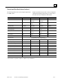
4
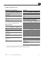
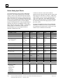
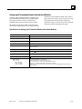
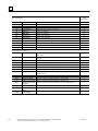
GMR Components List
Communications Interface Modules
Description
Catalog
Number
Cables, Etc...
TÜV
Approved
Refer To:
Description
Catalog
Number
Ethernet
IC697CMM741
Communication Module
**
Page 4-15
Multi-Drop SNP Cable
IC690CBL714
*
n/a
RS232/RS485 Converter IC690ACC901
*
n/a
Comm. Coprocessor
Module (CMM)
IC697CMM711
**
Page 4-13
Parallel I/O Expansion IC600WDXXX
Cables
*
n/a
Programmable
Coprocessor Module
(PCM)
IC697PCM711
**
Page 4-14
Parallel Bus Terminator
Plug
*
n/a
Genius Bus Controller
(GBC) Module
IC697BEM731
Yes
Page 4-17
**These communications interface modules may be used
in a TÜV approved system when the appropriate variable
write access protection is configured in the CPU.
Expansion Interfaces
Description
Catalog
Number
Bus Transmitter
Module
IC697BEM713F
Bus Receiver Module
IC697BEM711J
Field Control Genius
Bus Interface Unit
IC670GBI002/102
Field Control I/O
Terminal Block with
Barrier Terminals
IC670CHS001/101
Field Control I/O
Terminal Block with
Box Terminals
IC670CHS002/102
Field Control I/O
Terminal Block with
Wire to Board
Connectors
IC670CHS003/103
*
TÜV
Refer To:
Approved
Yes
Page 4-16
IC697ACC702
TÜV
Approved
Refer
To:
Termination Boards & Interface Modules
Description
Catalog
Number
TB, 16 Disc. Src Inputs
GBC1-SC-DI16
TB, 16 Disc. Sink Inputs
GBC1-SK-DI16
IM, 16 Disc. Src Inputs
IMC3-SC-DI16
IM, 16 Disc. Sink Inputs
IMC1-SK-DI16
TB, 32 Disc. Src Inputs
GBC1-SC-DI32
TB, 32 Disc. Sink Inputs
GBC1-SK-DI32
IM, 32 Disc. Src Inputs
IMC3-SC-DI32
TÜV
Refer To:
Approved
Yes
Page 4-27
Page 4-27
Yes
Page 4-27
Page 4-27
Yes
Page 4-27
Page 4-27
Yes
Page 4-27
Yes
Page 4-16
IM, 32 Disc. Sink Inputs
IMC1-SK-DI32
*
Page 4-31
TB, 6 Analog Inputs
GBC1-CK-AI6
Yes
Page 4-27
IM, 6 Analog Inputs
IMC3-CK-AI6
Yes
Page 4-27
TB, 16 Discrete Outputs
GBC1-CK-DO16
Yes
Page 4-27
IM, 16 Discrete Outputs
IMC4-CK-DO16
Yes
Page 4-27
TB, 32 Disc. Src Outputs
GBC1-SC-DO32
Yes
Page 4-27
Sink GBC1-SK-DO32
Yes
Page 4-27
Yes
Page 4-27
*
*
Page 4-32
Page 4-32
TB, 32
Outputs
*
Page 4-32
Disc.
Page 4-27
IM, 32 Discrete Outputs
IMC4-CK-DO32
TB to IM Cable
CBL1-CK-RRnn
Page 4-27
Cable w/2 ELCO 8016 CBL1-CK-EEnn
connectors
Page 4-27
Cable w/1 ELCO 8016
CBL1-CK-EBnn
connector, stripped,
tinned connectors at other
end
Page 4-27
All Series 90-70 PLC and Genius I/O products can be used in a GMR system, however, not all of the available
components are TÜV approved for use in the safety relevant portion of a system.
GFT-177A
Section 4 Product Specifications
4-3
4
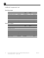
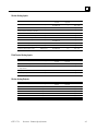
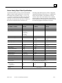
GMR I/O Components List
Genius Discrete Inputs
Description
Type
Catalog
Number
TÜV
Approved
Refer To:
24/48Vdc Source 15/16 Circuit
TMR/Simplex
IC660BBD020M
Yes
Page 4-20
24/48Vdc Sink 15/16 Circuit
TMR/Simplex
IC660BBD021M
Yes
Page 4-20
12/24Vdc Source 31/32 Circuit
TMR/Simplex
IC660BBD024N
Yes
Page 4-20
5/12/24Vdc Sink 31/32 Circuit
TMR/Simplex
IC660BBD025N
Yes
Page 4-20
115Vac 8 Circuit
Simplex
IC660BBD101
*
Page 4-21
115Vac/125Vdc 8 Circuit Isolated
Simplex
IC660BBS102
*
Page 4-21
115Vac/125Vdc 8 Circuit Isolated
Simplex
IC660BBS103
*
Page 4-21
115Vac 16 Circuit Isolated
Simplex
IC660BBD110
*
Page 4-21
Genius Discrete Outputs
Description
4-4
Type
Catalog
Number
TÜV
Approved
Refer To:
24/48Vdc Source 15/16 Circuit
TMR/Simplex/HSB
IC660BBD020M
Yes
Page 4-22
24/48Vdc Sink 15/16 Circuit
TMR/Simplex/HSB
IC660BBD021M
Yes
Page 4-22
24/48Vdc Source 31/32 Circuit
TMR/Simplex/HSB
IC660BBD024N
Yes
Page 4-22
5/24/48Vdc Sink 31/32 Circuit
TMR/Simplex/HSB
IC660BBD025N
Yes
Page 4-22
115Vac 8 Circuit
Simplex/HSB
IC660BBD101
*
Page 4-23
115Vac/125Vdc 8 Circuit Isolated
Simplex/HSB
IC660BBS102
*
Page 4-23
115Vac/125Vdc 8 Circuit Isolated
Simplex/HSB
IC660BBS103
*
Page 4-23
Relay N.C. 16 Circuit
Simplex/HSB
IC660BBR100
*
Page 4-23
Relay N.O. 16 Circuit
Simplex/HSB
IC660BBR101
*
Page 4-23
Genius® Modular Redundancy Flexible Triple Modular Redundant (TMR) System
Technical Product Overview – February 1998
GFT-177A
4
Genius Analog Inputs
Description
Type
Catalog
Number
TÜV
Approved
Refer To:
115Vac Volt/Current 4In/2Out
TMR/Simplex/HSB
IC660BBA100
*
Page 4-245
24/48Vdc Volt/Current 4In/2Out
TMR/Simplex/HSB
IC660BBA020
*
Page 4-24
115Vac/125Vdc Current Src. 4In/2Out
TMR/Simplex/HSB
IC660BBA104
*
Page 4-24
24/48Vdc Current Src. 4In/2Out
TMR/Simplex/HSB
IC660BBA024
Yes
Page 4-24
115Vac/125Vdc Current Src. 6 Input
TMR/Simplex
IC660BBA106
Yes
Page 4-24
24/48Vdc Current Src. 6 Input
TMR/Simplex
IC660BBA026
Yes
Page 4-24
115Vac/125Vdc R.T.D. 6 Input
TMR/Simplex
IC660BBA101
*
Page 4-24
24/48Vdc R.T.D. 6 Input
TMR/Simplex
IC660BBA021
Yes
Page 4-24
115Vac/125Vdc Thermocouple 6 Input
TMR/Simplex
IC660BBA103
*
Page 4-24
24/48Vdc Thermocouple 6 Input
TMR/Simplex
IC660BBA023
Yes
Page 4-24
Field Control Analog Inputs
Description
Type
Catalog
Number
TÜV
Approved
Refer To:
0–20 or 4–20mA, 8–Input Module
TMR/Simplex
IC670ALG230
*
Page 4-33
0–20, 4–20, or 4–24mA,
16–Input Module
TMR/Simplex
IC670ALG240
*
Page 4-33
RTD Input Module
TMR/Simplex
IC670ALG620
*
Page 4-33
Thermocouple Input Module
TMR/Simplex
IC670ALG630
*
Page 4-33
Genius Analog Outputs
Description
Type
Catalog
Number
TÜV
Approved
Refer To:
115Vac Volt/Current 4In/2Out
Simplex/HSB
IC660BBA100
*
Page 4-25
24/48Vdc Volt/Current 4In/2Out
Simplex/HSB
IC660BBA020
*
Page 4-25
115Vac/125Vdc Current Src. 4In/2Out
Simplex/HSB
IC660BBA104
*
Page 4-25
24/48Vdc Current Src. 4In/2Out
Simplex/HSB
IC660BBA024
Yes
Page 4-25
115Vac/125Vdc Current Src. 6 Out
Simplex/HSB
IC660BBA105
*
Page 4-25
24/48Vdc Current Src. 6 Out
Simplex/HSB
IC660BBA025
*
Page 4-25
GFT-177A
Section 4 Product Specifications
4-5
4
GMR I/O Components List
Additional Genius Components
Description
Type
Catalog
Number
TÜV
Approved
High Speed Counter (HSC) Block
Simplex/HSB
IC660BBD120
*
See GFK–0367
PowerTRAC Block
Simplex/HSB
IC660BPM100
*
See GFK–0366
for IC660BBA020
n/a
IC660SLA020
*
n/a
for IC660BBA021
n/a
IC660SLA021
*
n/a
for IC660BBA023
n/a
IC660SLA023
*
n/a
for IC660BBA024
n/a
IC660SLA024
*
n/a
for IC660BBA026
n/a
IC660SLA026
*
n/a
for IC660BBA100
n/a
IC660SLA100
*
n/a
for IC660BBA101
n/a
IC660SLA101
*
n/a
for IC660BBA103
n/a
IC660SLA103
*
n/a
for IC660BBA104
n/a
IC660SLA104
*
n/a
for IC660BBA106
n/a
IC660SLA106
*
n/a
for IC660BBD020
n/a
IC660SLD020
*
n/a
for IC660BBD021
n/a
IC660SLD021
*
n/a
for IC660BBD024
n/a
IC660SLD024
*
n/a
for IC660BBD025
n/a
IC660SLD025
*
n/a
Genius Hand Held Monitor
n/a
IC660HHM501
*
Page 4-27
Prefab Cable 15 Inch (qty. 3)
n/a
IC660BLC001
*
n/a
Prefab Cable 3 Foot (qty. 1)
n/a
IC660BLC003
*
n/a
Red “Safety” Labels (Qty. 20)
*
Refer To:
n/a
All Series 90-70 PLC, Field Control I/O, and Genius I/O products can be used in a GMR system, however, not all
of the available components are TÜV approved for use in the safety relevant portion of a system.
NOTE: Not listed here are more than 30 other Field Control I/O, rack-based I/O and special-purpose intelligent modules
which can be used in a simplex manner with GMR systems. Please contact your GE Fanuc Sales office for more details.
4-6
Genius® Modular Redundancy Flexible Triple Modular Redundant (TMR) System
Technical Product Overview – February 1998
GFT-177A
4
General Environmental Specifications
90-70 Components
Operating
Temperature
Storage Temperature
0 to 60° C (32 to 140°F)
0 to 40° C (32 to 104°F) for CPU model
CPM790 without forced air. See I/O racks for catalog
number of fan assembly.
–40° to 85° C (–40 to 185°F)
Humidity
5 to 95% non-condensing
Vibration
5–9 Hz 3.5mm displacement: 9–150 Hz at 1.0 G
Shock
15 Gs for 11 msec
Genius I/O Components
Operating
Temperature
0 to 60° C (32 to 140°F)
Storage Temperature
–40 to +100° C (–40 to +212° F)
Humidity
5 to 95% non-condensing
Vibration
5–10 Hz 5.08mm displacement, 10–200 Hz at 1.0 G
Field Control Components
Operating Temperature 0 to 55° C (32 to 131°F)
Storage Temperature
–40 to +85° C (–40 to +185° F)
Humidity
5 to 95% non-condensing
Vibration
10 to 57 Hz 0.012 in displacement (p–p) 57
to 500 Hz at 2 g (or as specified)
Shock
15G, 11 ms, half sine wave
Agency Approvals, Compliances, Standards _________________
TÜV
TÜV Rheinland – The Genius Modular Redundancy
system has been certified by TÜV Rheinland for the
following system configurations and classes:
n
n
n
Triple Modular Redundant (TMR 2v3) Fault
Tolerant and Fail Safe up to Class 6.
Duplex (2v2) Fail Safe up to Class 5.
Duplex (1v2) Fault Tolerant and Fail Safe up to Class 4.
For details and restrictions, refer to TÜV report 945/EL
340/96 or contact GE Fanuc for more information.
ISO
GE Fanuc Automation is ISO 9000 certified and ISO 9001
registered. GE Fanuc is also registered with Underwriters
Laboratories (USA), the British Standards Institute (UK) and
the Quality Management Institute of the Canadian Standards
Association.
Standards
Most GMR components (90-70, Field Control and Genius
I/O) comply with the following standards. However not
every component complies with every standard listed. For
specific information, please refer to the appropriate
technical manual or contact your GE Fanuc Sales office.
GFT-177A
Section 4 Product Specifications
IEC No. 142, C22.2
435,380
JIS A–1978
C 0912, JIS C ANSI/IEEE
0911
CSA
C22.2
C–37.90
DIN 871–877
435, 380
VDE
805, 806,
UL A
508, 1012
FCC
15J Part
2–230.40
VME
C.1
Hazardous Location
Class I, Div II .
NEMA/ICS
Those components identified earlier in the components
list of this document which were marked as being TÜV
approved (YES) also have passed the following tests per
the identified standards, which are required for TÜV
approval.
Cold test
Dry Heat test
Shock test
Change of Temp test
Damp Heat Cyclic test
Vibration test
Electrostatic Discharge
RF & Electromag. Immunity
Burst test
Surge test
Overvoltage test
P.S. Interrupt test
P.S. Variation test
IEC 68–2–1
IEC 68–2–2
IEC 68–2–27
IEC 68–2–14
IEC 68–2–30
IEC 68–2–6
IEC 801–2
IEC 801–3
IEC 801–4
ANSI/IEEE 37.90.1
DIN VDE 0160 – 7.3
DIN VDE 0116
DIN VDE 0116
4-7
4
Racks
Standard racks are available in five-slot panel-mount,
nine-slot panel mount, and 19-inch rack-mount styles.
Also available is a rack with 17 standard VME slots
which can be used to facilitate integration of 3rd-party
modules. It is also available in panel-mount or rackmount styles. Each of the racks can function either as the
main CPU rack or as an expansion rack.
Rack fan assemblies are available for use in installations
where heat buildup is a problem. The fans have a low
noise level and use ball bearings for extended life.
Module Retention
All Series 90-70 modules have molded latches that
automatically snap onto the upper and lower rails of the
rack when the module is fully inserted. Optionally
M2.5X8 screws may be used to secure the modules to the
rack for high vibration applications.
Slot Covers
Rack and Mounting Specifications
Height
Width
Depth
Nine Slot Rack
266mm
10.47”
483mm
19.00”
190mm
7.5”
Five Slot Rack
266mm
10.47”
320mm
12.6”
190mm
7.5”
Dimensions
Note: All modules extend 43mm (1.7”)
beyond the front of the rack.
Number of Slots:
5 or 9, plus power supply slot
Maximum 5 Volt
Current:
18 amps (with 100 watt power supply)
11 amps (with 55 watt power supply)
Current Required
from I/O bus:
0.5 amps
Ground Connection
Ground terminals are provided on each side of
the rack.
Ring terminal, star washer and AWG#12 wire
is recommended
I/O Reference
Assignment
User configurable via software (no switches)
Rack Identification
Rack select jumpers at back of power supply
slot
Unused rack slots should be covered with blank slot covers to
minimize connector exposure to foreign material.
Dimensions of a Standard Series 90-70 PLC Rack
WITH OPTIONAL VME J2 BACKPLANE KIT
19.00
(483)
1.00
(25.4)
9.14
(232)
18.11 11.71
(460) (297)
17.04 10.64
(433) (270)
7.25
(184)
REMOVABLE
I/O
TERMINAL
BLOCK
.75
(19)
6.75
(172)
CONNECTOR
FOR
POWER
SUPPLY
11.5
(292)
GND
STUD
GND
STUD
3.00
(76)
1.50
(38)
SPACER
(QTY.4)
2.24
(57)
SIDE VIEW
I/O TERMINAL
RESTRAINING STRAP
12.60
(320)
CABLE
ENTRANCE
FROM BOTTOM
HINGED
DOOR
.34
(8.64)
=
DIMENSIONS FOR
5 SLOT RACK
FRONT VIEW
.25 DIA. (TYPICAL)
DIMENSIONS IN INCHES, MILLIMETERS ARE IN PARENTHESIS
a42984
4-8
Genius® Modular Redundancy Flexible Triple Modular Redundant (TMR) System
Technical Product Overview – February 1998
GFT-177A
4
Power Supply Modules
CPU and expansion rack power supplies are inherently
redundant in the GMR system, because an individual
power supply is normally used in each rack. In some
configurations a single power supply may be used to
power both a CPU rack and an expansion rack by using a
power supply expansion cable.
Power supplies are available that handle input power
sources of 24 Vdc, 48Vdc, 125 Vdc, 120 Vac and 240
Vac. Power supplies are also available with different
output wattage capabilities up to 100 watts (at 60 degrees
C). Selection of a power supply can be tailored to the
needs of your system.
The input power source connects to the power supply
through a group of protected screw connections on the
front of the power supply module.
The module LED is visible through the transparent upper
portion of the door. The LED indicates the status of the
power supply. If the LED is off it indicates an overload
condition or output voltage levels that are out of
tolerance.
Each supply provides automatic overvoltage and
overcurrent protection for its DC outputs. Some supply
types include a replaceable input power fuse.
Most supply types have an on/off toggle switch located
inside the hinged door.
Power Supply Module with Door Open and with Door Closed
LOGIC POWER
LED
ON
On / OFF
Switch
OFF
POWER SUPPLY
POWER SUPPLY MODULE
120/240VAC
1.4A/0.7A
50/60HZ
INPUT
125 VDC
1.4A
+5V AT 20A
+12 AT 2A
OUTPUT
-12 AT 1A
100 WATTS
PROGRAMMABLE
CONTROLLER
WARNING:
DO NOT DISCONNECT
WHILE CIRCUIT IS
ALIVE UNLESS AREA
IS KNOWN TO BE
NONHAZARDOUS
Replace with same
type and rating
2A/250V
INPUT
+
L1
120/240VAC
N
Protected Input
Power Source
Screws
GFT-177A
125 VDC
Torque 12 in-lb
(1.3 N-m)
75_C Copper
Conductors
Section 4 Product Specifications
4-9
4
Dual Rack Configuration
Input Power Source Connections
The use of the power supply expansion cable
(IC697CBL700) provides the capability to power a
second rack (with +5 volts only) from the same power
supply if the power supply’s maximum current rating is
not exceeded.
The illustration below shows input power source
connections to the power supply through the protected
screw connections on the front of the module. The AC
input supplies have a jumper that must be attached to the
bottom terminals for 120Vac operation. This jumper
must be removed for 240Vac operation.
Example Power Connections
to the Power Supply
POWER
SUPPLY
FIRST
RACK
a47077
IC697
RACK STUD
(8-32)
TWO
RACK
POWER
CABLE
WARNING:
DO NOT DISCONNECT
WHILE CIRCUIT IS
ALIVE UNLESS AREA
IS KNOWN TO BE
NONHAZARDOUS
#12 (3.3 mm2)
GROUND
WIRE
Replace with same
type and rating
1A/250V
EARTH
GROUND
FACE
PLATE
SECOND
RACK
INPUT
HOT
+
L1
POWER
SOURCE
120/240VAC
N
NEUTRAL
125 VDC
-
Torque 12 in-lb
(1.3 N-m)
GROUND
75_C Copper
Conductors
a46611
MODEL # (IC697)
PWR710
PWR712
PWR711/713
Version H or later
PWR724
PWR731
PWR732
PWR748
Nominal Voltage
120/240Vac
120/240Vac or 125 VDC
24Vdc
125Vdc
48Vdc
Input Voltage
90–132
90-264
N/A
N/A
N/A
@ 47–63Hz (AC)
180–264
Input Vdc
N/A
100-150VAC
18–32
100–150
35–60
Input Power
90 Watts
160 Watts
160 Watts
100 Watts
90 Watts
Output Voltage
+5Vdc
+5,+12,–12Vdc
+5,+12,–12Vdc
+5,+12,–12Vdc
+5,+12,–12Vdc
Output Power
55.8 Watts
100 Watts
90 Watts
60 watts
90 Watts
Overvoltage Limit
5.7 – 6.7 Volts
5.7 – 6.7 Volts
5.7 – 6.7 Volts
5.7 – 6.7 Volts
5.7 – 6.7 Volts
Overcurrent Limit
12 – 14.5 amps
21 amp (5V)
26 amp (5V)
32 amp (5V)
26 amp (5V)
3.5 amp (+12V)
4 amp (+12V)
10 amp (+12V)
4 amp (+12V)
1.6 amp (–12V)
2 amp (–12V)
10 amp (–12V)
2 amp (–12V)
21 ms min.
10 ms min.
10 ms min.
10 ms min.
Holdup Time
4-10
21 ms min.
Genius® Modular Redundancy Flexible Triple Modular Redundant (TMR) System
Technical Product Overview – February 1998
GFT-177A
4
CPU Modules
Three Series 90-70 CPUs are available for TMR
applications. The high-performance CPM790 CPU, which
supports 2048 TMR I/O points, is based on a 64 MHz
80486DX2 microprocessor and includes a 1-megabyte
memory daughterboard.. The model 788 CPU supports
approximately 100 TMR I/O points and the model 789
CPU supports approximately 2048 TMR I/O points. Both
the 788 and 789 have a 16 Mhz 80386DX microprocessor
and occupy one slot in the CPU rack (with memory
daughterboard attached). Software configuration of the
CPUs is done using the LM90-70 programming and
configuration software--no switches or jumpers are used.
These CPUs execute both the GMR system software and the
application program logic. Application program logic is
typically written in ladder logic form, but Sequential Function
Chart (SFC) programming and “C” programming capabilities
also exist. These CPUs along with the GMR system software
perform the following functions:
n User application program execution
n Inter-CPU communications
n Majority voting of all inputs
n Input and output autotesting
n Input and output discrepancy checking
n General system diagnostics
n Fault reporting
The CPM790 CPU module includes 1 megabyte of memory.
Approximately 512K bytes of this memory is available for
the application program. The CPU 788 and 789 modules
require a 512K-byte memory daughterboard. Approximately
200K bytes of this memory is available for the application
program. This CMOS RAM is battery-backed by a lithium
battery on each CPU module. The battery can retain memory
contents for up to six months. The battery has a life of at least
ten years. The module has two battery connectors so a
replacement battery can be added before a “low” battery is
disconnected. A low battery, dead battery and missing
battery are all diagnosed and alarmed by the CPU.
Each of up to three CPUs in a system operates entirely
independent from each other CPU. The CPUs exchange
general status information, autotesting and fault information,
program checksum and configuration data checksum
information and optionally user application data via a built–in
global data facility. This information and data is exchanged
between the physically-isolated CPUs over the same Genius
I/O buses that are already present to interface to I/O modules.
Extensive CPU module and memory diagnostics are performed
both at powerup and continuously by each CPU. Faults are
logged in a PLC fault table which can be viewed with the
Logicmaster programming and configuration software. The
GFT-177A
Section 4 Product Specifications
other CPUs are made aware of any individual CPU faults by
reading status information.
Each CPU has a built-in RS-422/RS-485 serial port which is
typically used for a multi-drop connection to the programming
and configuration system. It can also be used for connection to
a host system or operator interface.
A three–position toggle switch can be used select Run Mode or
Stop mode. A Memory Protect prevents accidental program
changes (passwords can also be used). Four status LEDs (all
normally on) show the CPU’s status:
n “OK” LED – CPU diagnostic tests executed successfully
(no faults).
n “RUN” LED – CPU is in Run mode and executing
application program.
n “ENABLED” LED –CPU has enabled outputs to turn on/off as
set in the application program
n
“MEM PROTECT” LED – Memory Protect keyswitch is on.
CPU Module with Door Open
and with Door Closed
OK
RUN
ENABLED
LEDs
Mode
Selection
Switch
B
A
T
T
E
R
Y
MEM PROTECT
CENTRAL
PROCESSOR
UNIT
Dual
Battery
Connectors
RS-485
Serial
Port
a46612
4-11
4
CPU Module Specifications
MODEL # (IC697)
CPU788
CPU789
CPM790
Max. fully triplicated TMR Digital Inputs
112
2048
2048
Max. fully triplicated TMR Digital Outputs
80
2048
2048
Max. fully triplicated TMR Digital I/O (Combined I&O)
112
4096
4096
Max. Total Digital I/O
(Simplex, Duplex & TMR)
Depends on amount of TMR I/O)
352
12288
12288
Max. Total voted analog inputs
1024
1024
1024
Max. Total simplex inputs/outputs
8192
8192
8192
Maximum Application Program Size (Approximate)
200K bytes
200K bytes
512K bytes
Cooling Fans
Not required
Not required
Not required for
ambient <40° C
Fan kit is required for
ambient
>40° C
All Remaining CPU Module Specifications are common to the CPU788, CPU789, and CPM790.
Max. Register Table Size
16 Kwords
Max. Analog Inputs
8192 (Depends on amount of TMR Analog Inputs)
Max. TMR Analog Inputs
1024
Max. Analog Outputs
8192
Autotest Time Interval
0 to 65535 Minutes
Ladder Logic Execution Rate
Boolean = 0.4ms per 1024 elements
Lithium Battery for Memory Backup
3 Volt; 1000mA hours (6 months minimum retention)
Clock
Battery Backed Calendar Clock
Ladder Instruction Set
Contacts, Coils, Links, Timers, Counters, Bit Operation, Conversion,
Relational, Control, Math, Data Table and Data Move
WatchDog Timer
Configurable from 10 to 2250 milliseconds
Digital Vote Type
2 out of 3 (also configurable for 2oo2, 1oo2, or 1oo1)
Analog Vote Type
Mid–value select (also for duplex–average, high or low select)
Degradation Options
3–2–1–0 or 3–2–0 (available for inputs, outputs, and CPUs)
On–Line Programming
Configurable as Enabled or Disabled
Write Protection for Application Program Variables
Configurable limits for (%R, %I, %Q, %AI, %AQ, %T, %M and %G)
Processor Synchronization
None – Asynchronous
Effect of CPU Failure
None – Remaining CPU(s) will report loss of CPU only and continue to
operate
4-12
Genius® Modular Redundancy Flexible Triple Modular Redundant (TMR) System
Technical Product Overview – February 1998
GFT-177A
4
Communications Modules
Communications Coprocessor Module (CMM)
each CPU can support multiple CMMs mounted in either
the CPU rack or an expansion rack.
The Communications Coprocessor Module
(CMM) provides Communications Control (CCM),
Remote Terminal (RTU) and Series Ninety (SNP)
communications. CCM, RTU (slave)* and SNP
are available on the serial ports in nine selectable
combinations: CCM/CCM, CCM/RTU,
RTU/CCM, RTU/RTU, SNP/SNP, SNP/CCM,
CCM/SNP, SNP/RTU, and RTU/SNP.
Three status LEDs at the top of the module indicate
“module OK” and “Port 1” and “Port 2” transmit/receive
activity. A single pushbutton in located beneath the LEDs
and can be pushed to reinitialize communications at both
serial ports. No other switches or jumpers exist on the
board – configuration is accomplished by using the LM9070 programming and Configuration software. The CMM
module utilizes a 12 Mhz 80C186 microprocessor.
CCM
Functions in CCM mode are: read/write of register,
input and output tables; bit set/clear of inputs and
outputs; read scratch pad; Q sequence commands
for fast reads; and modify diagnostic status word.
In the master and peer CCM configurations the
CMM module initiates communications with other
devices through the application program.
CMM Module with Door Open
LEDs
Restart
Pushbutton
RTU
In the RTU Slave protocol, the following functions
are provided: read input and output tables; read
analog input; read register table; read scratch pad;
read exception status; force a single or multiple
outputs; preset a single or multiple registers; report
device type and perform loopback maintenance.
RTU master protocol is available in the PCM
module with application code.
SNP
Each serial port on the CMM can be configured to
provide SNP master or slave capability. The SNP
protocol on the CMM module provides read and write
access to registers, inputs, outputs, analog inputs,
analog outputs, %T, %M, %P, %L and %G variable
types. Full Series Ninety datagram capability and
many status and control functions are also supported.
An “autodial” feature is provided to control a Modem.
SNP-X extensions to the SNP protocol provide high
performance read and write access to the same
variable types listed above. SNP-X is especially
useful for high-speed data acquisition and control in
multidrop configurations. In the master SNP
configurations the CMM module initiates
communications with other devices through
application program communications requests.
The CMM provides both the RS-232 and RS-485
Interfaces and communicates with the CPU over
the backplane. It is typical in a GMR system to use
one CMM in each of up to three CPUs, however
GFT-177A
Section 4 Product Specifications
RS-232
RS-485
Serial Port
RS-232
RS-485
Serial Port
a46613
MODEL # (IC697)
CMM711
Protocols
CCM, RTU, SNP/SNP–X
Port # 1 Interface type
RS–232 or RS–422/RS–485
Port # 2 Interface type
RS–232 or RS–422/RS–485
Port #1 Max Data Rate 19.2 Kbps (full duplex)
Port #2 Max Data Rate 19.2 Kbps (full duplex)
Dual Port Max Data 19.2 Kbps (full
Rate
simultaneously
duplex)
on
both
Battery
None Required
Microprocessor
12 Mhz 80C186
Configuration
Via LM90-70 Software (No Switches or
Jumpers)
port
4-13
4
Communications Modules (continued)
Programmable Coprocessor Module (PCM)
The Programmable Coprocessor Module (PCM)
functions as a coprocessor to the CPU. It can be
programmed to perform operator interface, real-time
computations, data storage and custom protocols for
data acquisition or data communications functions.
CCM2 functions provided by the PCM module are:
read/write of register, input and output tables; bit
set/clear of inputs and outputs; read scratch pad; Q
sequence commands for fast reads; and modify
diagnostic status word. In the master and peer CCM
configurations, the PCM module initiates
communications with other devices through
application program requests.
The PCM communicates with the CPU over the
backplane. It can access user and system data using
extensions to the powerful Megabasic language. No
application program support is required in the PLC
CPU. Multiple PCMs can be supported by each CPU.
The PCM board has up to 95 Kbytes of user memory.
In addition, a PCM can accommodate an optional
expansion memory daughterboard up to 512 Kbytes in
size. Both types of memory are backed by a
replaceable lithium battery.
MODEL # (IC697)
PCM711
Dual Tasking
CCM/Megabasic
Protocols
CCM2 or Custom via Megabasic
application program.
Port # 1 Interface type
RS–232 or RS–422/RS–485
Port # 2 Interface type
RS–232 or RS–422/RS–485
Port #1 Max Data Rate
19.2 Kbps (full duplex)
Port #2 Max Data Rate
19.2 Kbps (full duplex)
Dual Port Max Data
Rate
19.2 Kbps (full duplex) on both port
simultaneously
Microprocessor
12 Mhz 80C186
Memory
Up to 96 Kbytes of battery backed
CMOS RAM on board
Expansion Memory
64, 128, 256 or 512 Kbytes battery
backed CMOS RAM
Lithium Battery for
Memory Backup
3 Volt; 1000mA hours (6 months
minimum retention)
Clock
Real time calendar clock synchronized
to GMR CPU
Configuration
Via LM90–70 Programming and
Configuration Software or PCM
Development Software (No Switches or
Jumpers)
Controls/Indicators
Reset Pushbutton / Three Status LEDs
4-14
The PCM has three Status LEDs. One indicates the condition of
the module (Module OK). The others may be assigned a function.
The module pushbutton is used to restart a PCM application or to
set the PCM to its factory default configuration but retain any
application program. Both serial ports are RS-232 and RS422/485 compatible. Both ports operating simultaneously can
support up to 19.2 Kbaud full duplex communications.
The PCM is a dual-tasking processor; a custom Megabasic
program can run while the PCM is being used as a
communications interface.
Software is used to configure the port parameters, to define
the interface to the CPU, to select task functions and to
program Megabasic applications. Configurations include:
n CCM only – CCM2 master, slave or peer on both ports.
n BASIC – Megabasic only where the Megabasic
application has access to both serial ports.
n BAS/CCM – Megabasic and CCM2 together. The
Magabasic application has access to port 1 and port 2 is
used as a CCM communication interface.
PCM Module with Door Open
LEDs
Restart
Pushbutton
Dual
Battery
Connectors
RS-232
RS-485
Serial
Port
Expansion
Memory Board
RS-232
RS-485
Serial
Port
Genius® Modular Redundancy Flexible Triple Modular Redundant (TMR) System
Technical Product Overview – February 1998
a46614
GFT-177A
4
Communications Modules (continued)
Ethernet Modules
The Ethernet Controller module (IC697CMM741)
provides direct connection to IEEE 803.2 CSMA/CD
LANs. The module has an 802.3 standard D-connector
for attachment of a user-supplied AUI (Attachment Unit
Interface) or transceiver cable. The AUI cable connects
directly to a user-supplied transceiver that is directly
connected to the 10Mbps Ethernet network. The
transceiver must be 802.3 compatible and must have the
SQE option.
The Ethernet Interface (Type 2) Module
(IC697CMM742) provides high-performance TCP/IP
communications. The module’s 10BaseT and 10Base2
ports permit direct connection to a network without an
external transceiver. The AUI port permits attachment to
a user-supplied AUI cable and user-supplied transceiver.
Ethernet Interface Module
ETHERNET
INTERFACE
These Ethernet modules plug into a single slot of a PLC
rack. Module LEDs indicate status. The module’s Restart
pushbutton is used to restart the module and to reload the
software. A local serial port is provided to connect to the
Factory LAN System Manager (GSM) terminal. The
communications software may be loaded through this
port.
Note: Fault-tolerant redundant serial communications can
be provided by using communications modules in rack 1
and rack 2.
Model #
(IC697)
TCP/IP, MMS/OSI,
SRTP
Interface
IEEE 802.3 CSMA/CD Medium Access Control 10
Mbps
Media
10Base5, 10Base2, 10BaseT, 10BaseF, 10Broad36
Software
Stored in RAM Memory – easily updated
System
Management
Tools
GSM System Manager provides Network
Performance Measurement, Fault Diagnosis,
Configuration Management and Software
Downloading
Configuration
Via LM90–70 Programming and Configuration
Software “Soft Switches
Controls,
Indicators
Restart Pushbutton / Three
Status LEDs
STATUS
Station Manager
Serial Port
Service Option
Connector
Software Load
(RS-485)
Serial Port
10BaseT
Network
Port
RESTART
STATION
MGR
232
SERVICE
OPTION
S/W
LOAD
RS
485
AUI
OR
10Base2
Network Port
GFT-177A
Restart Pushbutton /
Four Status LEDs
S
E
R
I
A
L
C
O
N
N
E
C
T
I
O
N
S
10
BASE
T
OR
AUI Network
Port
TCP/IP, SRTP
LAN ONLINE
SERIAL
Restart Pushbutton
CMM742
Protocols
Supported
MODULE OK
LEDs
CMM741
E
T
H
E
R
N
E
T
C
O
N
N
E
C
T
I
O
N
10
BASE
2
Section 4 Product Specifications
4-15
4
Bus Transmitter & Bus Receiver Modules
Bus Transmitter and Receiver Modules permit expansion
from the main GMR CPU rack to a maximum of 7
additional racks, using up to 50 feet (15 meters) of
interconnecting cable.
PARALLEL
P
S
C B
P T
U M
Main Rack
Programmer
Model # (IC697)
BEM713(BTM) and
BEM711(BRM)
Expansion Racks Supported
7 Maximum
Parallel Programmed Interface
(included on BTM)
High Performance 500
Kbytes/Second
Time to Store 16 Kbyte
Program
20 to 30 seconds
Maximum Cable Length
50 Feet (15 Meters) Total
Effective I/O Data Rate
500 Kbytes/Second
Electrical Isolation
Non-isolated Differential
Communications
B
R
M
Bus Transmitter or Bus Receiver Module
with Door Open
NOTE
B
R
M
P
S
TOTAL LENGTH OF ALL
INTERCONNECTING CABLES
FROM BTM TO LAST BRM IS 50
FEET (15 METERS) MAXIMUM.
ALL RACKS MUST BE AT SAME
GROUND POTENTIAL (8
RACKS MAXIMUM).
LEDs
B
R
M
a46617
The Bus Transmitter Module is used in the main CPU
rack to begin the daisy chain of rack(s) using parallel I/O
cables (IC600WDFXXX – where XXX = length in feet).
The upper connector on the BTM can be used as a high–
performance interface to the (running LM90–0
programming and configuration software). The bottom
connector of the BTM is for daisy chain cable
connections between the Main CPU rack and all
expansion racks. LEDs at the top of the BTM module
provide Module OK, Programmer Port Enabled, and
Expansion Port Enabled status information.
Expansion
Port
Expansion
Port
The Bus Receiver Module is used in each of the
expansion racks and is always installed in slot one. Both
connectors in the BRM are for connections between
racks. LEDs on the BRM module provide Rack
Configured, Termination Installed and Expansion Port
Enabled status information.
4-16
Genius® Modular Redundancy Flexible Triple Modular Redundant (TMR) System
Technical Product Overview – February 1998
a42986
GFT-177A
4
Genius Bus Controller Module
The Genius Bus Controller (GBC) is a single-channel
controller that occupies a single rack slot in either the
CPU rack or any expansion rack. Its primary purpose is
to interface the I/O subsystem to the GMR CPUs.
Multiple GBCs may be installed in each rack to suit the
I/O capacity needs for an application.
The front of the module provides a port for direct
connection of a Genius Hand-held Monitor and screw
terminals for the Genius bus.. Two LEDs show Module
OK and Channel One OK status information.
The Bus Controller scans I/O blocks asynchronously and
transfers I/O data to the GMR CPU once per CPU scan
over the backplane of the rack. The Bus Controller also
passes fault information from the I/O devices to the GMR
CPU, which time-stamps faults and queues them in a
table.
Typically, three Genius Bus Controllers are used per
GMR PLC for a triplex GMR bus. Two triplicated GMR
Buses are shown in the following drawing of a triplex
GMR system. Alternatively, two Genius Bus Controllers
can be used for a duplex GMR bus or a single Genius Bus
Controller for a simplex GMR bus or a “non-GMR bus”.
Triplex GMR System with Two Triplicated Busses
PLC A
PLC B
C GG G G GG
P BBB B BB
U CC C C CC
A ABC A BC
C G GG G G G
P BBB B BB
U C CC C C C
B ABC A BC
PLC C
C
P
U
C
G GG G G G
BBB B BB
C CC C C C
ABC A BC
Bus A
Bus B
Bus C
Bus A
Bus B
Bus C
Genius Bus Controller Module with Door Open
46618
LEDs
Additional Genius Bus Controllers can be outside the
scope of the GMR configuration but still part of a GMR
system. Through the exchange of directed
communications (datagrams) and global data, they can
serve as communications nodes linking other devices and
provide peer–to–peer information transfer. Such a
network can provide communications between multiple
PLCs and host computers.
Connector
for Genius
Hand-held
Monitor
Terminals for
Connecting
Genius Bus
Cable
MODEL # (IC697)
BEM731
Devices Supported per
Bus
28 Blocks Typical – 31 Maximum
(including up to 3 GBCs and 1 HHM)
Communications Rates
153.6 Kbaud Standard, 153.6 Kbaud
Extended, 76.8 Kbaud, 38.4 Kbaud
Maximum Cable Lengths 2000 feet @ 153.6 Kbaud Standard
3500 feet @ 153.6 Kbaud Extended
4500 feet @ 76.8 Kbaud
7500 feet @ 38.4 Kbaud
Configuration
Via LM90–70 Programming and
Configuration Software (No Hardware
Switches or Jumpers)
Effect of Failure of One
GBC in a group
None – Loss of IOC reported – other
GBC(s) in the redundant group continue
to operate
a42985
GFT-177A
Section 4 Product Specifications
4-17
4
Genius I/O Network
Each Genius serial bus conveys data by passing a “token”
among the devices. When the token is received by a
device it is that device’s turn to communicate. A “bus
scan” occurs when all devices on the bus have received
the token one time. During one bus scan the GBC
receives all inputs from all blocks, receives any fault
information from all blocks, updates all outputs on the
I/O blocks, sends any commands received from the CPU.
The Genius bus scan is independent and asynchronous
from the GMR CPU sweep.
a43528
Bus Scan Cycle
The Genius I/O network interfaces Genius I/O blocks to the
GMR PLC system. It serves as a communications interface to
pass startup, diagnostic and application data between the CPUs
of the GMR PLC system. The Genius network also provides
an open–architecture interface to a variety of third–party
devices including personal computers.
Typical bus cable is shielded twisted pair or twinaxial
cable. No special connectors are required; saddle-clamp
screw connectors are provided on all devices. Each
physical end of a bus is terminated with appropriate
termination resistors which are provided. Fiber optics
cable with modems can be used for long distance
requirements or if additional isolation is required.
The Genius network operates at 4 speeds up to 153.6K
baud. The maximum length of a network depends on the
speed selected; it can be up to 7,500 feet. Maximum bus
cable lengths depend on which of four baud rates is
selected and the cable type as shown in the chart below.
Cable #
& Make
Outer
Diameter
Terminating
Resistor*
–10%to+20%
1/2 Watt
Number of
Conductors/
AWG
BUS
CONTROLLER
TOKEN PATH
(DEVICE 31)
1
Dielectric
Voltage
Rating
2
3
30
Maximum Length Cable Run,
feet/meters at baud rate
Ambient
Temp
Rating
153.6s
153.6e
76.8
38.4 l
(A)9823
(B)9182
(C)4596
(M)M39240
.350in
8.89mm
150 ohms
2 / #22
30v
60ºC
2000ft
606m
3500ft
1061m
4500ft
1364m
7500ft
2283m
(B)89182
.322in
8.18mm
150 ohms
2 / #22
150v
200ºC
2000ft
606m
3500ft
1061m
4500ft
1364m
7500ft
2283m
(B)9841
(M)M3993
(A)9818C
(B)9207
(M)M4270
.270in
6.86mm
.330in
8.38mm
*120 ohms
2 / #24
30v
80ºC
100 ohms
2 / #20
300v
80ºC
1000ft
303m
1500ft
455m
1500ft
455m
2500ft
758m
2500ft
758m
3500ft
1061m
3500ft
1061m
6000ft
1818m
(A)9109
(B)89207
(C)4798
(M)M44270
.282in
7.16mm
100 ohms
2 / #20
150v
200ºC
1500ft
455m
2500ft
758m
3500ft
1061m
6000ft
1818m
(A)9818D
(B)9815
(O)911264**
.330in
8.38mm
.260in
6.60mm
.approx 50in
12.7m
.315in
8.00mm
100 ohms
2 / #20
100 ohms
2 / #22 flexing
250v
80ºC
100 ohms
4 pairs #24 (solid)
>150v
80ºC
1500ft
455m
1500ft
455m
1500ft
455m
2500ft
758m
2000ft
606m
2000ft
606m
3500ft
1061m
3000ft
909m
3000ft
909m
6000ft
1818m
4500ft
1364m
4500ft
1364m
100 ohms
4 (two pair) #22
150v
60ºC
1200ft
364m
1700ft
516m
3000ft
909m
4500ft
1364m
.274in
6.96mm
100 ohms
4 (two pair) #22
150v
200ºC
1200ft
364m
1700ft
516m
3000ft
909m
4500ft
1364m
.243in
6.17mm
75 ohms
2 / #20
150v
60ºC
800ft
242m
1500ft
455m
2500ft
758m
3500ft
1061m
.244in
6.20mm
75 ohms
4 (two pair) #22
300v
80ºC
200ft
60m
500ft
152m
1200ft
333m
2500ft
758m
((E)532185
BBDN
(A)9818
(B)9855
(M)M4230
(A)9110
(B)89696
(B)89855
(A)9814C)
(B)9463
(M)M4154
(A)5902C
(B)9302
(M)M17002
Notes:
4-18
A = Alpha, B = Belden, C = Consolidated, E = Essex, M = Manhattan, O = Olflex
l = Limited to 16 taps at 38.4 Kbaud, ** = Suitable for applications requiring high flexibility, continuous flex or vibration.
Genius® Modular Redundancy Flexible Triple Modular Redundant (TMR) System
Technical Product Overview – February 1998
GFT-177A
4
Genius I/O Blocks
Genius I/O blocks provide a full range of I/O types and
densities. All block types may be used in a GMR system
as non-critical or simplex I/O. A subset of the available
blocks may be used as GMR I/O. Genius I/O blocks
make it possible to distribute I/O in quantities as low as 6
points, Distributed and remote placement of the I/O at the
point of control reduces problems associated with large
amounts and lengths of control wiring. Genius I/O blocks
can also be grouped at a central location (e.g. in a main
control panel).
assembly. All active components are located in the
electronics assembly portion of the block, which can be
removed without disturbing the field wiring.
Electronics
Assembly
Retaining
Screws
Genius I/O Block
Terminal
Assembly
GENIUS
24/48 VDC
Source In/Out
GE Fanuc
Genius blocks have no switches or jumpers and are
software-configured via a Hand-Held Monitor (HHM).
This “soft” configuration is stored in the terminal
assembly so there is no need to reconfigure if an
electronics assembly is changed. Genius blocks are
unique in that many types allow each circuit to be
configured as either an input or an output, providing
excellent flexibility and the ability to easily customize the
I/O system to the application. In the tables that follow,
you will see these block types listed in both the input
section and the output section.
2A/Pt Max 15A Max Total
a44485
Each Genius I/O block is a standalone unit with built-in
power supply, microprocessor and Genius network
communications circuitry. Each block is made of cast
aluminum and weighs about 4 pounds (1.8Kg). The size
of most block types is approximately 9” (22cm) high x
3.5” (9cm) wide x 4” (10cm) deep.
Each block consists of a matching terminal assembly and
electronics assembly. The terminal assembly forms the
base of the block and is electrically and mechanically
keyed to accept only an electronics assembly of the same
type. All field connections are made to the terminal
GFT-177A
Section 4 Product Specifications
In addition to individual circuit indicators on most blocks,
every block provides two diagnostic LEDs which show
the health of the block and its individual circuits, and
show whether a block is online or has a forced circuit.
The I/O data for each block is communicated over the
Genius bus with the Genius Bus Controllers in GMR
PLCs, Blocks can be located up to 7500 feet (or more by
using fiber optics Modems) and form a truly distributed
I/O system.
All blocks can be used in a GMR system as simplex I/O.
Those identified in the tables that follow can also be used
as triplex, duplex or in the case of some outputs, in a Hot
Stand By (HSB) mode. Optional field termination boards
are available to facilitate the wiring of TMR blocks.
4-19
4
Genius Discrete Input Block Specifications
The blocks listed on this page may be used as TMR input
blocks or as simplex input blocks in a GMR system. For
these blocks, the duplicate and triplicate input data is
received at all GMR CPUs and then voted just prior to
executing the application program to ensure the highest
integrity of the input data used. Selected discrete input
blocks can diagnose stuck-on and stuck-off input circuit
electronics and diagnose circuit-to-circuit shorts. Some
blocks also provide supervised input diagnostics (input
shorted to +24Vdc).
A failure of a block or circuit results in both the
appropriate block diagnostic LED indication and the fault
being logged into fault tables of each PLC. TMR inputs
continue to operate with the remaining blocks or “legs”
of the input group. Failed TMR input blocks may
replaced hot (power on) without disturbing the
functioning portion of the input group or any other part of
the system.
MODEL # (IC660)
BBD020*
BBD021*
BBD024*
BBD025*
Number of Points (With Autotest)
15
15
31
31
Number of Points (W/O Autotest)
16
16
32
32
Nominal Voltage
24/48Vdc
24/48Vdc
12/24Vdc
5/12/24Vdc
Source or Sink Operation
Source
Sink
Source
Sink
DC Voltage Range
18–56
18–56
10–30
10–30 & 4.9–5.3
Required DC Power (Max.)
300ma
300ma
300ma
300ma
Block Isolation
1500V
1500V
850V
850V
Point Status LEDs
1 per point
1 per point
1 per point
1 per point
Diagnostic LEDs
–––––––Unit OK (Block or Point Fault Indication)––––––––––
–––I/O Enabled (On–Line and Forced Point Indication)––––
Supervised Input Diagnostic
Yes
Yes
n/a
n/a
P.S. Dropout Time
10 ms
10 ms
4ms @ 12V
4ms @ 12V
20ms @ 24V
20ms @ 24V
Operating Modes
TMR/HSB
TMR/HSB
TMR/HSB
TMR/HSB
SIMPLEX
SIMPLEX
SIMPLEX
SIMPLEX
Input Autotest (Stuck On/Off)
Yes
Yes
Yes
Yes
Input Autotest (Channel–to–Channel Short)
Yes
Yes
Yes
Yes
Loss of Block Diagnostic
Yes
Yes
Yes
Yes
Selectable Filter Time
5–100ms
5–100ms
1–100ms
1–100ms
Input Impedance (Typical)
5.6 K ohms
5.6 K ohms
3.3 K ohms
3.3 K ohms
On Threshold (12Vdc Power)
n/a
n/a
8–12Vdc
0–4Vdc
On Threshold (24Vdc Power)
16–24Vdc
0–8Vdc
18–24Vdc
0–6Vdc
On Threshold (48Vdc Power)
32–48Vdc
0–16Vdc
n/a
n/a
Off Threshold (12Vdc Power)
n/a
n/a
0–6Vdc
6–12Vdc
Off Threshold (24Vdc Power)
0–7Vdc
17–24Vdc
0–12Vdc
12–24Vdc
Off Threshold (48Vdc Power)
0–14Vdc
34–48Vdc
n/a
n/a
Weight
–––––––––––––––––––––––4 lbs. (1.8 kg)–––––––––––––––––––––––––––––
* These blocks can operate as inputs or outputs in any combination when in HSB or Simplex Mode
4-20
Genius® Modular Redundancy Flexible Triple Modular Redundant (TMR) System
Technical Product Overview – February 1998
GFT-177A
4
Discrete Input Block Specifications Continued
The following blocks can be used as simplex input blocks
in a GMR system.
Simplex input blocks also provide a variety of diagnostic
capabilities depending on the block type. Please refer to
the Genius I/O User’s Manuals for more details.
MODEL # (IC660)
BBD101*
BBD102*
BBD103*
BBD110
Number of Points
8 Grouped
8 Isolated
(4 Groups)
8 Isolated
(4 Groups)
16 Grouped
Nominal Voltage
115Vac
115Vac
115Vac
115Vac
125Vdc
125Vdc
Operating Modes
SPLX/HSB
SPLX/HSB
SPLX/HSB
SIMPLEX
AC Voltage Range (47–63Hz)
93–132
93–132
93–13
93–132
DC Voltage Range
n/a
105–132
105–132
n/a
P.S. Dropout Time
1 Cycle
1 Cycle
1 Cycle
1 Cycle
10ms DC
10ms DC
Block Isolation
1500V
1500V
1500V
1500V
Point Status LEDs
1 per point
1 per point
1 per point
1 per point
Diagnostic LEDs
––––––––Unit OK (Block or Point Fault Indication)–––––––––––
––––I/O Enabled (On–Line and Forced Point Indication)––––––
Open Input Diagnostic
Yes
Yes
Yes
Yes
Shorted Input Diagnostic
No
No
No
Yes
Loss of I/O Power Diagnostic
Loss of Block
Yes
Yes
Loss of Block
Selectable Filter Time
10–100ms
10–100ms
10–100ms
10–100ms
Input Impedance (Typical)
13 K ohms
13 K ohms
13 K ohms
11.6 K ohms
AC On Threshold (Normal Mode)
95 VRMS
95 VRMS
95 VRMS
programmable
AC Off Threshold (Normal Mode)
60 VRMS
60 VRMS
60 VRMS
programmable
DC On Threshold (Normal Mode)
n/a
90 Vdc
90 Vdc
n/a
DC Off Threshold (Normal Mode)
n/a
55 Vdc
55 Vdc
n/a
Weight
–––––––––––––––––––––––––4 lbs. (1.8 kg)––––––––––––––––––––––––––––
* These blocks can operate as inputs or outputs in any combination
GFT-177A
Section 4 Product Specifications
4-21
4
Genius Discrete Output Block Specifications
The Genius blocks listed below may be used as GMR
Output blocks or as Hot Standby or simplex blocks in a
GMR system Output data is received individually from
each GMR CPU by each output block in a group and then
to ensure the highest integrity of the data used, the output
block group votes the data before driving critical loads on
or off.
Most output blocks employ electronic overload and short
circuit protection, which allow an output circuit to be
reset without the need to replace a fuse and cause a fault
to be logged in the fault table of each GMR CPU. Please
refer to the Genius I/O user’s manuals for more details. A
failure of a block or circuit results in both the appropriate
block diagnostic LED indication and fault logged into
fault tables of each PLC. TMR outputs continue to
operate with the remaining blocks or “legs” of the output
group. Failed TMR output blocks may replaced hot
(power on) without disturbing the functioning portion of
the output group or any other part of the system.
MODEL # (IC660)
Weight
BBD020*
BBD021*
BBD024*
BBD025*
–––––––––––––––––––––––4 lbs. (1.8 kg)–––––––––––––––––––––––––––––
Nominal Voltage
24/48Vdc
24/48Vdc
12/24Vdc
5/12/24Vdc
Source or Sink Operation
Source
Sink
Source
Sink
Operating Modes
TMR/HSB
SIMPLEX
TMR/HSB
SIMPLEX
TMR/HSB
SIMPLEX
TMR/HSB
SIMPLEX
Number of Points
16
16
32
20ms @ 24V
32
20ms @ 24V
DC Voltage Range
18–56
18–56
10–30
10–30 & 4.9–5.3
Required DC Power (Max.)
300ma
300ma
300ma
300ma
P.S. Dropout Time
10 ms
10 ms
4ms @ 12V
4ms @ 12V
Block Isolation
1500V
1500V
850V
850V
Point Status LEDs
1 per point
1 per point
1 per point
1 per point
Diagnostic LEDs
–––––––Unit OK (Block or Point Fault Indication)––––––––––
–––I/O Enabled (On–Line and Forced Point Indication)––––
Diagnostics Available:
Loss of Block
Short Circuit
Overload
No Load
Failed Switch
Overtemp
Output–to–Output Short
Short to +24 Vdc
Short to 0 Vdc
Yes
Yes
Yes
Yes
Yes
Yes
Yes
Yes
Yes
Yes
Yes
Yes
Yes
Yes
Yes
Yes
Yes
Yes
Yes
Yes
No
No
Yes
No
Yes
Yes
Yes
Yes
Yes
No
No
Yes
No
Yes
Yes
Yes
Steady State Output Current
2 amps
2 amps
0.5 amps
0.5 amps
Max. Inrush Current (for 10 ms)
10 amps
10 amps
4 amps
4 amps
Total Current per Block @35°C
15 amps
15 amps
16 amps
16 amps
Output Off Leakage Current
1.0 ma
1.0 ma
10 µa
10 µa
Output Voltage Drop
2.0 V max.
2.0 V max.
2.0 V max.
2.0 V max.
Minimum Load with No–Load Enabled – TMR
100 ma
100 ma
n/a
n/a
* These blocks can operate as inputs or outputs in any combination when in HSB or Simplex Mode
4-22
Genius® Modular Redundancy Flexible Triple Modular Redundant (TMR) System
Technical Product Overview – February 1998
GFT-177A
4
Discrete Output Block Specifications Continued
The blocks listed below, used individually, can operate in
either a simplex mode, duplex mode or Hot Stand By
(HSB) mode. HSB is a mode in which a block uses
output data from only one CPU unless that CPU fails, in
which case the block uses output data from an alternate
CPU.
MODEL # (IC660)
BBD101*
BBD102*
BBD103*
BBR100
BBR101
Number of Points
8 Grouped
8 Isolated
8 Isolated
16 Isolated
(4 Groups)
(4 Groups)
(4 Groups)
115Vac
115Vac
115/230Vac
125Vdc
125Vdc
Nominal Voltage
115Vac
Operating Modes
SPLX/HSB
SPLX/HSB
SPLX/HSB
SPLX/HSB
AC Voltage Range (47–63Hz)
93–132
93–132
93–132
5–250
DC Voltage Range
n/a
105–132
105–132
5–220
P.S. Dropout Time
1 Cycle
1 Cycle
1 Cycle
1 Cycle
10ms DC
10ms DC
Block Isolation
1500V
1500V
Point Status LEDs
1 per point
1 per point
Diagnostic LEDs
–––––––––Unit OK (Block or Point Fault Indication)–––––––––––
––––I/O Enabled (On–Line and Forced Point Indication)––––––
Diagnostics Available:
Loss of Block
Loss of I/O Power
Short Circuit
Overload
No Load
Failed Switch
Overtemp
Yes
No
Yes
Yes
Yes
Yes
Yes
Yes
Yes
Yes
Yes
Yes
Yes
Yes
Yes
Yes
Yes
No
No
No
Yes
Yes
No
No
No
No
No
No
Steady State Output Current
2amps RMS
2 amps
2 amps
2 amps
Max. Inrush Current (for 2 cycles AC or
10 ms DC)
25amps peak
25 amps
25 amps
2 amps
Total Current per Block @35°C
15 amps
15 amps
15 amps
125VA/pnt.
Output Off Leakage Current
< 7 ma
7 ma AC
2 ma DC
7 ma AC
2 ma DC
0.1 ma
Output Voltage Drop
2.5 V max.
2.5 V max.
2.5 V max.
2.0 V max.
Minimum Load with No–Load Enabled
50 ma
50 ma
50 ma
n/a
Weight
–––––––––––––––––––––––––4 lbs. (1.8 kg)––––––––––––––––––––––––––––
* These blocks can operate as inputs or outputs in any combination
GFT-177A
Section 4 Product Specifications
4-23
4
Genius Analog Input Blocks
All of the listed block types may be used as TMR Analog
input blocks. These blocks include those that can handle
Voltage, Current, R.T.D., and Thermocouple input signals.
TMR Analog input blocks function in a group of up to three
blocks (of the same type). The duplicate and triplicate input
data is received at all GMR CPUs and then voted just prior to
executing the application program to ensure the highest
integrity of the input data used. Voting on triplicated data is
mid-value select with the vote adapting to average, selecthigh or select-low in the event of a failure. A second failure
results in further vote adaptation to either use the last
operational input or go to a preconfigured minimum,
maximum or hold-last-state value.
A failure of a block or circuit results in both the
appropriate block diagnostic LED indication and the fault
being logged into fault tables of each PLC. TMR analog
inputs continue to operate with the remaining blocks or
“legs” of the input group. Failed TMR analog input
blocks may replaced hot (power on) without disturbing
the functioning portion of the input group or any other
part of the system.
All analog input blocks provide a variety of diagnostic
capabilities. In addition, the blocks perform automatic
self–calibration of internal circuitry. Please refer to the
Genius I/O user’s manuals for more details.
AC MODEL # (IC660)
BBA100
BBA104
BBA106
BBA101
BBA103
DC MODEL # (IC660)
Number of Points
(BBA020)
4In/2Out
(BBA024)
4In/2Out
(BBA026)
6 In
(BBA021)
6 In R.T.D.
(BBA023)
6 In T.C.
Operating Modes
TMR/HSB
SIMPLEX
TMR/HSB
SIMPLEX
TMR/
SIMPLEX
TMR/
SIMPLEX
TMR/
SIMPLEX
Input Range(s)
or Linearization (RTD)
or T.C. Types (T.C.)
4–20ma
0–10Vdc
–10–+10Vdc
0–5Vdc
–5–+5Vdc
4–20ma
4–20ma
Platinum
Nickel
Copper
Linear
Type J, K, T, E, B,
R, S, N
Nominal P.S. Voltage (AC)
115
115
115
115
115
Nominal P.S. Voltage (DC)
(24/48)
125
125
125
125
(24/48)
(24/48)
(24/48)
(24/48)
AC Voltage Range (47–63Hz)
98–132
93–132
93–132
93–132
93–132
DC Voltage Range
(18–56)
105–145
(18–56)
105–145
(18–56)
105–145
(18–56)
105–145
(18–56)
P.S. Dropout Time
1 Cycle
10ms DC
1 Cycle
10ms DC
1 Cycle
10ms DC
1 Cycle
10ms DC
1 Cycle
10ms DC
Block Isolation
1500V
1500V
1500V
1500V
1500V
Common Mode Rejection
60dB
0–1Khz
45dB
50,60Hz
45dB
50,60Hz
Common Mode Voltage
+/– 170V
Input Resolution
12 bits (+ sign)
1µa
1µa
0.1°C
<+/–4µv
Accuracy (@ 25°C)
+/–0.2% Typ
0.1%
0.1%
+/–0.5°C Typ
Input Filter Ranges (ms)
0–1024
16.6–400
16.6–400
400–1600
Diagnostic LEDs
–––––––––––––––––Unit OK (Block or Point Fault Indication)–––––––––––––––––
–––––––––––I/O Enabled (On–Line and Forced Point Indication)–––––––––––––
<+/–10µv
2000
Diagnostics Available:
Loss of Block
Under/Overrange
High/Low Alarm
Open Wire
Input Shorted
Wiring Error
Internal Fault
Yes
Yes
Yes
Yes
No
No
No
Weight
––––––––––––––––––––––––––––––––––4 lbs. (1.8 kg)–––––––––––––––––––––––––
4-24
Yes
Yes
Yes
Yes
No
No
No
Yes
Yes
Yes
Yes
No
No
No
Genius® Modular Redundancy Flexible Triple Modular Redundant (TMR) System
Technical Product Overview – February 1998
Yes
Yes
Yes
Yes
Yes
Yes
Yes
YEs
Yes
Yes
Yes
No
No
Yes
GFT-177A
4
Genius Analog Output Block Specifications
All of the listed block types may be used as Hot Standby
(HSB) or simplex analog output blocks. These blocks
include those that can handle Voltage (+/–10v, 0–10v,
+/–5v and 0–5v) and Current (4–20ma) type loads. Hot
Stand By is a mode in which a block uses output data
from only one CPU unless that CPU fails, in which case
the block uses output data from an alternate CPU.
All analog output blocks provide a variety of diagnostic
capabilities depending on the block type. In addition the
blocks perform automatic self-calibration of internal
circuitry. Please refer to the Genius I/O user’s manuals
for more details. A failure of a block or circuit results in
both the appropriate block diagnostic LED indication and
the fault being logged into fault tables of each PLC.
AC MODEL # (IC660)
BBA100
BBA104
BBA105
DC MODEL # (IC660)cd
(BBA020)
(BBA024)
(BBA025)
Number of Points
4In/2Out
4In/2Out
6 Out
Operating Modes
HSB/SPLX
HSB/SPLX
HSB/SPLX
Output Range(s)
4 to 20ma
0 to 10Vdc
–10 to +10Vdc
0 to 5Vdc
–5 to +5Vdc
4–20ma
4–20ma
Nominal P.S. Voltage (AC)
115
115
115
Nominal P.S. Voltage (DC)
(24/48)
125
(24/48)
125
(24/48)
AC Voltage Range (47–63Hz)
98–132
93–132
93–132
DC Voltage Range
(18–56)
105–145
(18–56)
105–145
(18–56)
P.S. Dropout Time
1 Cycle
10ms DC
1 Cycle
10ms DC
1 Cycle
10ms DC
Block Isolation
1500V
1500V
1500V
Common Mode Rejection
60dB
0–1Khz
45dB
50,60Hz
Common Mode Voltage
+/– 170V
Accuracy (@ 25°C)
+/–0.2% Typ
0.15%
0.15%
Output Resolution
12 bits (+ sign)
6µa
6µa
Output Update Frequency
4ms
6–8ms
25ms
Output Load (Voltage Mode)
>2000ohms
n/a
n/a
Output Load (Current Mode)
0–300ohms
0–850ohms
0–850ohms
Diagnostic LEDs
–Unit OK (Block or Point Fault Indication)–
–I/O Enabled (On–Line and Forced Point Indication)––
Diagnostics Available:
Loss of Block
Under/Overrange
Feedback Error
Yes
Yes
No
Weight
GFT-177A
Yes
Yes
Yes
Yes
Yes
Yes
––––––––––––––––4 lbs. (1.8 kg)–––––––––––––––––
Section 4 Product Specifications
4-25
4
Genius Hand-Held Monitor
The Hand-Held Monitor (HHM) is a convenient
maintenance, configuration and operator interface tool
for use with Genius I/O blocks, Field Control I/O
Stations, and networks. Its main functions in a GMR
system are to initially configure each Genius block and
Field Control I/O Station, to assist in verifying I/O
wiring and the operation of each I/O point, and to
monitor the performance of an I/O network. Longerterm, it can be used as a maintenance and
troubleshooting tool to track down faults and read
detailed fault information from any I/O block or Field
Control I/O module. It is typically used temporarily and
not permanently-connected to a system. The HHM
connects to any Genius I/O network at any I/O block,
Field Control I/O Station, or Genius Bus Controller
(GBC). The ability to connect the HHM at any point on
a network provides remote monitoring of any device. A
Monitor/Configure keyswitch allows the configuration
of the Hand-Held Monitor to either restrict or allow the
HHM to access certain functions such as clearing faults,
making I/O block or module configuration changes, and
forcing of I/O circuits. The HHM display is menu–
driven and utilizes four function keys to select menu
items. The HHM can be easily upgraded by replacing a
socketed PROM which defines its functions.
charger/adapter unit. In battery operation, an auto-off
circuit can be enabled to prolong battery life.
The HHM can also be continuously powered via an AC
charger/adapter from a 115 or 230 Vac power source.
120V
Voltage
Selection
Switch
230V
46620
The NiCad battery pack can be easily replaced with
freshly-charged pack for continued operation. An
optional auto-shutoff feature prevents unintentional
battery drain if a key is not pressed within 10 minutes.
Genius Hand-held Monitor
Mode Select
Keyswitch
GENIUS
46621
MODEL # (IC660)
HHM501
Display
4 line /16 character each line (0.2” – 5mm
high)– LCD
Keyboard
20 key sealed membrane with tactile
feedback
Keyswitch
2 position Monitor/Configure (with 2 keys)
Battery
NiCad pack providing 6 hours of operation
with a full charge
Hand Held Monitor
GE Fanuc
HHM
Cable
F1
F2
F3
F4
7
8
9
Home
4
5
6
s
Menu
1
2
3
Clear
+
-
0
D
On
Off
Connection for Charger/Adapter
Function Keys
Battery Charger
115/230Vac 15%, 47–63 Hz
Decimal Keys
Communications
Cable
5 feet (1.5 meter) coiled
Operation
Keys
Weight
1.3 lbs. (0.6 Kg) without case , 1.8 lbs. (0.8
Kg) with case
Size (HxWxD)
8”x3.75”x1.25” without case,
10.85”x4.3”x2.25” with case
Display Languages
English, German, French, or Italian
Communication Data
Rates
153.6 Kbaud Standard, 153.6 Kbaud Ext.,
76.8 Kbaud, or 38.4 Kbaud
46619
After system initialization, the HHM is a versatile startup and maintenance tool. At any time, the HHM itself
can be configured and locked so that functionality may
be restricted to preset parameters. The HHM may be
battery operated for up to 6 hours, or run off the AC
4-26
Genius® Modular Redundancy Flexible Triple Modular Redundant (TMR) System
Technical Product Overview – February 1998
GFT-177A
4
Genius Block GMR Termination Boards and Interface Modules
The illustration below represents an input interface
module with three ribbon connectors; the output interface
module has four.
Termination boards and interface modules which can be
used to simplify the integration of Genius blocks into
redundant groups have been developed by Silvertech
Limited. Termination boards and interface modules are
available for 2- or 4-block discrete output groups and for
2- or 3-block discrete and analog input groups. The use of
termination boards and interface modules is optional.
Discrete Input Termination Boards and
Interface Modules
Discrete input termination boards are available for 16point and 32-point sink and source Genius blocks.
Complementary discrete input interface modules are
available with polarized locking two-part connectors for
I/O wiring.
The interface modules perform basic grouping and
conditioning of I/O device signals. The termination
boards interface these signals to the Genius blocks,
performing any additional signal conditioning if
necessary.
Discrete input termination boards and interface modules
incorporate all the diodes needed for the input autotest
feature; no other diodes are required. In addition, the
termination board includes circuitry to support the
asynchronous input autotest feature. The tristate, or
supervised, input feature of 16-point blocks can be used
with these termination boards.
Interface modules are DIN-rail mountable, with
connectors for the I/O devices and termination board
wiring. 34-wire ribbon cables (the mating connector and
cable are not supplied) are used to connect interface
modules with termination boards. The interface module
segregates I/O wiring from internal panel wiring.
Termination boards attach to the side of each Genius
block in a group. The board is held in position by its
connection pins which are inserted into the screw
terminals of the Genius block. Spacers on the termination
board provide the necessary clearance between the board
and the Genius block. The termination board also has a
connector for power and ground wiring (where
appropriate).
The discrete input interface module provides the grouping
and distribution of the power and input signals. Each
input is protected from a short circuit in the power wiring
by a self-resetting thermistor. No fuse replacement is
needed.
Input autotest may be disabled by jumpering two
terminals on the termination boards. All 16 or 32 points
are then available as inputs.
Spacer
Power and
Ground
Terminals
Termination Board
S1
S2
SHLD IN
SHLD OUT
Input Interface
Module
I/O Wiring
Connector
Ribbon Cable
GFT-177A
Section 4 Product Specifications
4-27
4
16-Point Discrete Input Termination Boards and Interface Modules
Operating voltage
20V to 32V DC
Temperature range
0 degrees C to +60 degrees C
Humidity
5% to 95% non-condensing
Connectors: Interface Module
One ELCO male 8016 series, 38-pin exposed contacts.
Three 34-pin IDC connectors for ribbon cable
Size: Termination Boards
219mm length X 95mm width X 30mm depth
Size: Interface Modules
145mm length X 109 mm width X 101mm depth (including mating connector, including
mounting bracket)
External Inputs
GMR Mode: 15/16 normally closed switches with zener diodes in series for tristate inputs
(15 with autotest). Non-GMR Mode: 15/16 normally open switches with zener diodes in
parallel for tristate inputs (15 with autotest).
Open Switch Voltage
Bistate or tristate GMR Mode: supply voltage . Tristate non-GMR Mode: zener voltage
Closed Switch Current
Bistate: 11mA at 24V supply . Tristate, GMR Mode: 7mS at 24V supply. Tristate, nonGMR Mode: 11mA at 24V supply
Silvertech part numbers
GBC1-SC-DI16
GBC1-SK-DI16
IMC3-SC-DO16
IMC3-SK-DO16
CBL1-CK-RRnn
CBL1-CK-EEnn
CBL1-CK-EBnn
Termination Board for 16-circuit Source block
Termination Board for 16-circuit Sink block
Interface Module for 16-circuit Source block group.
Interface Module for 16-circuit Sink block group.
34-way ribbon cable, termination board to interface module
Field device connection cable with 2 ELCO 8016 connectors
Field device connection cable with 1 ELCO 8016 connector and stripped and tinned
connectors at the other end.
Specifications for 32–Point Discrete Input Termination Boards and Interface Modules
Operating voltage
16V to 30V DC
Temperature range
0 to +60 degrees C
Humidity
5% to 95% non-condensing
Connectors: Interface Module
Two 32-point ELCO male 8016 series, 38-pin exposed contacts. Three 34-pin IDC
connectors for ribbon cable
Size: Termination Boards
219mm length X 110 mm width X 30mm depth
Size: Interface Modules
145mm length X 109 mm width X 101mm depth (including mating connector, including
mounting bracket)
External Inputs
32 switched inputs with Short Circuit protection31 with autotest
Open Switch voltage
Supply voltage – 1V
Closed Switch current
7mA per point per Genius Block. 21mA max. with 3 blocks at 24V.
Silvertech part numbers
GBC1-SC-DI32
GBC1-SK-DI32
IMC3-SC-DI32
IMC3-SK-DI32
CBL1-CK-RRnn
CBL1-CK-EEnn
CBL1-CK-EBnn
4-28
Termination Board for 32-circuit Source block
Termination Board for 32-circuit Sink block
Interface Module for 32-circuit Source block group.
Interface Module for 32-circuit Sink block group.
34-way ribbon cable, termination board to interface module Field device connection
cable with 2 ELCO 8016 connectors
Field device connection cable with 1 ELCO 8016 connector and stripped and tinned
connectors at the other end.
Genius® Modular Redundancy Flexible Triple Modular Redundant (TMR) System
Technical Product Overview – February 1998
GFT-177A
4
Analog Input Termination Boards and Interface Modules
An analog input termination boards is available for the
6-point current input Genius block. A complementary
analog input interface module is available with a
polarized locking two-part connector for I/O wiring.
The analog input interface module converts the input
current into a voltage signal via a precision resistor for
distribution to the termination boards. The resistor is
fully protected from short circuits in the power wiring.
The termination board incorporates a high input
impedance voltage-to-current converter for each point
which is powered by the point power supply.
Specifications for Analog Input Termination Boards and Interface Modules
Operating voltage
18V to 56V DC
Temperature range
0 to +60 degrees C
Humidity
5% to 95% non-condensing
Connectors: Interface Module
One ELCO male 8016 series, 38-pin exposed contacts.
Three 34-pin IDC connectors for ribbon cable
Size: Termination Boards
219mm length X 95mm width X 30mm depth
Size: Interface Modules
145mm length X 109 mm width X 101mm depth (including mating connector, including
mounting bracket)
External Inputs
6 point isolated 4-20mA current input for sink or source operation
Input Impedance
230 Ohms + 5%
Input Protection
Thermistor limited to less than 100mA typical
Signal Accuracy
+0.2% over temperature
Silvertech part numbers
GBC1-CK-0I6
IMC3-CK-AI6
CBL1-CK-RRnn
CBL1-CK-EEnn
CBL1-CK-EBnn
GFT-177A
Termination Board for 6-circuit blocks
Interface module for 6-circuit input block group
34-way ribbon cable, termination board to interface module
Field device connection cable with 2 ELCO 8016 connectors
Field device connection cable with 1 ELCO 8016 connector and stripped and tinned connectors
at the other end.
Section 4 Product Specifications
4-29
4
Discrete Output Termination Boards and Interface Modules
Discrete output termination boards are available for 16point and 32-point sink and source Genius blocks.
Complementary discrete output interface modules are
available with polarized locking two-part connectors
for I/O wiring.
Both the 16- and 32-point discrete interface modules
group the output signals and incorporate a diode for
each point to prevent reverse load leakage current. It is
highly recommended that an external kickback
suppression diode be fitted to the field loads.
The 16-point discrete output uses a single termination
board type which operates with either sink or source
blocks. The 32-point source block termination board
incorporates a self–indicating fuse, in accordance with
TÜV recommendations, which is visible from the
installed position. A blown fuse will be revealed during
the output autotest.
The termination boards and interface module can easily
be configured for either a 4-block or 2-block output
arrangement.
Specifications for 16-Point Discrete Output Termination Boards and Interface Modules
Operating voltage
20V to 36V DC
Temperature range
0 degrees C to +60 degrees C
Humidity
5% to 95% non-condensing
Connectors: Interface Module
One ELCO male 8016 series, 38-pin exposed contacts. Four 34-pin IDC connectors for ribbon cable
Size: Termination Boards
219mm length X 95mm width X 30mm depth
Size: Interface Modules
145mm length X 109 mm width X 101mm depth
Outputs
16 loads at 2 Amps per channel max, 15 Amps total at 35°C
Load Voltage at 1A
Supply Voltage –2V typical
Minimum Load
100mA with No Load Reporting enabled
Silvertech part numbers
GBC1-CK-DO16
IMC4-CK-DO16
CBL1-CK-RRnn
CBL1-CK-EEnn
CBL1-CK-EBnn
Termination Board for Source or Sink block
Interface Module for 16-circuit output block group.
34-way ribbon cable, termination board to interface module
Field device connection cable with 2 ELCO 8016 connectors
Field device connection cable with 1 ELCO 8016 connector and stripped and tinned connectors at the other
end.
Specifications for 32-Point Discrete Output Termination Boards and Interface Modules
4-30
Operating voltage
10V to 30V DC
Temperature range
0 degrees C to +60 degrees C
Humidity
5% to 95% non-condensing
Connectors: Interface
Module
Two ELCO male 8016 series, 38-pin exposed contacts. Four 34-pin IDC connectors for ribbon cable.
Size: Termination Boards
219mm length X 110mm width X 30mm depth
Size: Interface Modules
145mm length X 109 mm width X 101mm depth
Outputs
32 loads at .5 Amps per channel max
Load Voltage at .5A
Supply Voltage –1V typical
Fusing
0.5A indicating fuses, Bussman type GMT
Silvertech part numbers
GBC1-SC-DO32
GBC1-SK-DO32
IMC4-CK-DO32
CBL1-CK-RRnn
CBL1-CK-EEnn
CBL1-CK-EBnn
Termination Board for 32-circuit Source block
Termination Board for 32-circuit Sink block
Interface Module for 32-circuit output block group.
34-way ribbon cable, termination board to interface module
Field device connection cable with 2 ELCO 8016 connectors
Field device connection cable with 1 ELCO 8016 connector and stripped and tinned connectors at the other end.
Genius® Modular Redundancy Flexible Triple Modular Redundant (TMR) System
Technical Product Overview – February 1998
GFT-177A
4
Field Control Bus Interface Units and I/O Modules
Field Control modules, which are mounted on separate
terminal assemblies, are interfaced to a Genius bus by a
Genius Bus Interface Unit. Together, the Bus Interface
Unit and its modules are referred to as an “I/O Station.”
A Field Control I/O Station can be used in a GMR
system as GMR inputs or as non-GMR I/O. It can not
be used for GMR outputs or non-voted GMR inputs
and it cannot be autotested.
Field Control I/O Station
modules, such as fault reporting, output defaults, analog
range selection, and analog scaling.
The BIU has four status LEDs and a connector for a Handheld Monitor. The BIU provides logic power for the
modules in the station. External power must be supplied for
field wiring of I/O devices. The BIU mounts on a separate
terminal block, to which all of the bus wiring is connected.
The configuration of the I/O station is stored in the BIU
terminal block
BIUs IC670GBI002F or GBI102A or later support Hot
Insertion/Removal of I/O modules. Modules can be removed
and replaced while station power is applied without affecting
the BIU and other modules in the I/O Station. Separate
power must be off to the module being inserted or removed.
Hot Insertion/Removal requires I/O modules having catalog
number suffix J and above and I/O Terminal Blocks
IC670CHS101, 102, or 1034.
Bus Interface
Unit Module
Terminal Block with
Communications and
Power Terminals for
Bus Interface Unit
Bus Interface Unit IC670GBI002 operates on 24VDC.
IC670GBI102 operates on 115VAC/125VDC.
I/O Modules
Field Control I/O Modules
Field Control I/O modules are available in a wide range of
I/O types and densities. All module types may be used in a
GMR system as non-critical or simplex I/O. Field Control
analog input modules may be used as TMR I/O.
I/O Terminal Block
Field Control Analog Input Module
DIN Rail
46403
I/O Terminal Blocks provide universal field wiring terminals
for two I/O modules, allowing I/O module types to be mixed
on the same I/O Terminal Block. The I/O Terminal block is
mounted on a DIN rail. The DIN rail, which is an integral part
of the grounding system, must be mounted to a panel.
As many as eight Field Control I/O modules (four I/O
terminal blocks) can be connected to one Bus Interface
Unit. One optional 21-inch (0.53 meter) cable
(IC670CBL002) can be used per Field Control station.
The remaining connections must be made using the
shorter connectors supplied with the bases.
Bus Interface Units
The Bus Interface Unit provides the I/O scanning,
diagnostics, and communications capabilities needed to link
the I/O modules to the control system. In addition, the Bus
Interface Unit may provide many characteristics for I/O
GFT-177A
Section 4 Product Specifications
Status
LED
46406
Field Control I/O modules are small rugged components
with sturdy aluminum housings. Modules are approximately
3.25 inches (8.2 cm) high x 2 inches (5.25 cm) wide. They
are 2.90 inches (7.3 cm) deep
I/O Module LEDs are easily visible through the
transparent central portion of the label. Analog input
modules have one module status LED. Discrete
modules also have individual circuit LEDs that show
the on/off status of each input or output circuit.
4-31
4
I/O Terminal Blocks
Terminal Styles
I/O Terminal Blocks are generic wiring bases for Field
Control I/O modules. They provide I/O module
mounting, backplane communications, and terminals
for user connections.
I/O Terminal Blocks are available with the I/O terminal
styles shown below. Different I/O Terminal Block
types can be intermixed within a station.
Modules screw onto the terminal block for vibration
resistance. I/O modules can be removed from the I/O
Terminal Block without disturbing field wiring.
Field Control I/O Terminal Block
Terminals
for
Module 1
16
14
12
10
8
6
4
2
B
15
13
11
9
7
5
3
1
A
Keying Slots
16
14
12
10
8
6
4
2
B
15
13
11
9
7
5
3
1
Keying Slots
Cable Connector
A
Panel Mounting Foot
Terminals
for
Module 2
Panel Mounting Foot
Cable Connector
DIN rail latch
Barrier
Terminals
Wire to Board
Connectors
46418
DIN rail latch
46418
The I/O Terminal Block has two separate sets of
module terminals. Each set corresponds to a “slot” in
a conventional rack-type PLC.
The cable connectors provide easy attachment of the
cable that carries communications signals.
The DIN rail latches clip the I/O Terminal Block to a
DIN rail
The keying slots permit protective module keying.
4-32
Box
Terminals
The I/O Terminal Block with Barrier Terminals
(catalog number IC670CHS101) has 37 terminals. Each
terminal can accommodate one or two wires up to
2
AWG #14 (avg 2.1mm cross section).
The Terminal Block with Box Terminals (catalog
number IC670CHS102) has 51 terminals, each of
2
which accommodates one AWG #14 (avg 2.1mm cross
2
section) to AWG #22 wire (avg 0.36mm cross
2
section), or two wires up to AWG #18 (avg. 0.86mm
cross section). An insulated external 5mm (0.2in)
jumper such as Altech #8879 can be used to connect
adjacent points. When an external jumper is used, the
2
wire capacity is reduced from AWG #14 (2.10mm ) to
2
AWG #16 (1.32mm ).
The I/O Terminal Block with Connectors (catalog
number IC670CHS103) has two 20-pin male
connectors for I/O wiring. The mating connector is
Amp part number 178289-8. The connectors are keyed
to prevent wrong insertion. Any tin-plated contact in
the AMP D–3000 series can be used with the connector
(Amp part number 1-175217-5 for high contact force
receptacle for 20-24 gauge (0.20–0.56mm2) wires), 1175218-5 for high contact force receptacle for 16-20
gauge (0.56-1.42mm2)). A kit containing two mating
connector housings and contacts is available as GE
Fanuc part number C670ACC003.
Genius® Modular Redundancy Flexible Triple Modular Redundant (TMR) System
Technical Product Overview – February 1998
GFT-177A
4
Field Control Module Specifications
The Bus Interface Units Field Control analog input modules
and Terminal Blocks listed below may be in GMR input
groups. TMR Analog inputs are provided by a group of up
to three Field Control I/O stations with modules of the same
type. The duplicate and triplicate input data is received at all
GMR CPUs and then voted just prior to executing the
application program to ensure the highest integrity of the
input data used. Voting on triplicated data is mid-value select
with the vote adapting to average, select-high or select-low in
the event of a failure. A second failure results in further vote
adaptation to either use the last operational input or go to a
preconfigured minimum, maximum or hold-last-state value.
A failure of a BIU, module, or circuit results in both the
appropriate diagnostic LED indication and the fault being logged
into fault tables of each PLC. TMR analog inputs continue to
operate with the remaining “legs” of the input group.
Bus Interface
Units
I/O Terminal
Blocks
IC670ALG630
IC670GBI002
IC670GBI102
(IC670CHS 101,
102, and 103)
Field Control Analog Input Modules
Catalog Number
IC670ALG230
IC670ALG240
IC670ALG620
Number of Points
8 In
16 In
4 In RTD
8 Thermocouple or
Millivolt Inputs
--
--
Operating Modes
TMR/
SIMPLEX
TMR/
SIMPLEX
TMR/
SIMPLEX
TMR/
SIMPLEX
TMR/
SIMPLEX
TMR/
SIMPLEX
Input Range(s)
or Linearization
(RTD)
0–20ma
4–20ma
0–20ma
4–20ma
0–24ma
Platinum, Copper,
Nickel,
Nickel/Iron,
Resistance
Inputs from J, K, T, E,
S, R, B, N, G, C, D,
Platinel II
Thermocouples
Spans from +/-19.5mV
to +/-625mV
--
--
Nominal P.S. Voltage
24VDC
24VDC
Powered from BIU
Powered from BIU
24VDC (GBI002)
--
115VAC, 125VDC
(GBI102)
--
18-30VDC
(GBI002)
90-135VAC, 105150VDC (GBI102)
--
1500VAC for 1 min,
250 VAC continuous
--
--
120dB / 50, 60Hz
--
--
250V RMS
--
--
Voltage Range
18–30VDC)
20–28VDC
--
Isolation
1500VAC for 1
min, 250 VAC
continuous
1500VAC
1500VAC for 1
min, 250 VAC
continuous
Common Mode
Rejection
--
86db
120dB / 50, 60Hz
Common Mode
Voltage
None
None
250V RMS
Input Resolution
5µa
381 nanoamps
(16 bits)
15 bits (+ sign)
15 bits (+ sign)
--
--
Accuracy (@ 25°C)
+/–0.05% Typ
0.05%
+/–0.15% Typ
+/–0.15% Typ
--
--
Input Filter Ranges
(ms)
RC
10ms/20ms
digital
--
--
--
--
--
--
Diagnostic LED
–––––––––– Module status –––––––––
Diagnostics Available:
Loss of Block
Under/Overrange
High/Low Alarm
Open Wire
Input Shorted
GFT-177A
Yes
Yes
Yes
Yes
No
Yes
Yes
Yes
Yes
No
Section 4 Product Specifications
Yes
Yes
Yes
Yes
Yes
Yes
Yes
Yes
Open T’couple
Thermistor error
4-33
Section
5
T
Configuring &
Programming
a GMR System
M
R
G M R
TM
The purpose of this section is to explain the basics of GMR system software setup and programming.
The illustration below is an overview of configuration and programming for three GMR 788/798 or 790
PLCs. Both the special GMR Software and the Logicmaster 90-70 Software contribute to the system
configuration and to the completed application program. Genius I/O blocks and Field Control BIUs in the
system are independently configured.
Basic GMR System Configuration and Programming Steps
GMR CONFIGURATION
LM90 CONFIGURATION
GMR
Configuration
Printout
GMR
Diskette
788/789
CONFIG.EXE
GMRxxyy
KEY0.DEF
LM90
Copy Folder
LM90 PROGRAMMING
G_M_R10
Program
Block
LM90
Librarian
790
LM90
Copy Folder
G_M_R_ _
Program
Folder
LM90
Copy Folder
Embed
Config.
Data
The
Application
Program
CONFIGA
CONFIGB
CONFIGC
future
program
updates
LM90
Store
PLC A
LM90
Store
PLC B
LM90
Store
PLC C
I/O Block Configuration with
Hand-held Monitor
GFT-177A
5-1
5
GMR Configuration
The GMR characteristics of a system are set up using
special GMR software on a personal computer.
n
n
The GMR configuration is the same for the redundant PLCs;
there is only one GMR configuration for the system.
Fault actions for the system
All GBC (bus controller) groups, with all Genius I/O
blocks that will use GMR features
The GMR configuration presents the configuration items as
choices on menu screens like the examples on this page.
Typical GMR Configuration Screen
The GMR Configuration Software automatically supplies
default values. Only items that are different from the
defaults need to be changed. Configurable items include:
n
n
n
5-2
n
I/O addresses and other features of GMR block
groups:
n
For each circuit, synchronous or asynchronous
Autotest, at intervals ranging from 1 minute to more
than 45 days.
n
How long inputs may be discrepant before the CPU
places a message in the I/O Fault Table and sets a
fault contact. The range is 1 second to 18 hours.
Starting addresses and lengths for any memory areas
to which data can be written to through a CMM,
PCM, or Ethernet Communications Module.
The number of CPUs, CPU type, ability to
enable/disable online programming, ability to shut
down if only one PLC remains operating, timeout
period from 1 second to 18 hours.
I/O limits for the system
Initialization data for the system
n
Genius® Modular Redundancy Flexible Triple Modular Redundant (TMR)
System Technical Product Overview – February 1998
GFT-177A
5
PLC System Configuration
The overall PLC system configuration is completed using
the Logicmaster 90-70 software, which also runs on a
personal computer. Modules are quickly selected from
lists by function key. It is possible to completely
configure the system offline with no PLC hardware
present.
Zooming into a slot shows a detailed description of the
module configuration:
Detail Screen for a Module
Typical Module Type Selection Menu
Automatic Configuration Documentation
After selecting a module, it appears on a screen that
represents that rack being configured.
Example Rack Definition Screen
The configuration information for the GMR system can
be sent to a printer so a hard copy of the current
configuration documentation is easily prepared. The
information may also be exported to documentation
software under the DOS or Windows operating systems.
I/O Configuration
Genius I/O blocks and Field Control Bus Interface Units
in the system are configured separately to assign
parameters such as address, type, diagnostics, operation,
communication, and mode settings.
GFT-177A
Section 5 Configuring & Programming a GMR System
5-3
5
Programming
The Logicmaster 90-70 software is also used to create the
Relay Ladder Logic GMR application program. An
example screen of logic during edit is shown below. The
top of the Logicmaster screen always shows the current
assignments of the function keys, which are used to select
program functions. For example, on the program editing
screen illustrated below, the second row shows Contacts.
Each Contact can be selected with one key press. The
status information at the bottom of the screen can be
turned off for even more program display area.
Function Blocks for Complex Functions
Function blocks simplify programming complex functions
in the GMR application program using Relay Ladder
Logic. Multiple parameters are easily included in a
function block, in a clearly-understood fashion. The
illustration screen below shows two Addition function
blocks.
Example Function Block
Example Relay Logic with Contacts
The Series 90-70 PLC provides a large and extremely
versatile set of coils, contacts, relational functions, logical
functions, and many advanced functions for use in the
application program. They are described in the table that
begins on page 5-10.
For more complex function blocks, a ZOOM feature
opens a window on the instruction.
The same application program is used for each GMR
PLC, eliminating the need for individual logic programs
and simplifying user programming.
Application programming assistance is available from
your GE Fanuc sales office, or GE Fanuc’s 24 hour
support hotline @ 804 978–5747.
Through Logicmaster 90, the GMR CPU supports
structured programming techniques. Program logic can
be separated by functionality, equipment areas, or other
logical sections. The GMR programmer may write an
efficient program with reduced effort using structured
programming tools, which include:
n
n
n
5-4
Function Blocks for complex functions
Custom Parameterized Subroutine Blocks
Program Blocks
Genius® Modular Redundancy Flexible Triple Modular Redundant (TMR)
System Technical Product Overview – February 1998
GFT-177A
5
Program Blocks
Programming Languages
Program blocks can be used to organize program
sections. Up to 255 program blocks can be declared in
the main program block. Program blocks may be
individually “Locked”. That aids software security while
allowing access to required functions such as specific
timers, counters, and other data.
The main part of the GMR application program is created
in familiar Relay Ladder Logic. Additional program
blocks can be in Relay Ladder Logic or in ‘C’. Program
Blocks in ‘C’ are created externally and imported into the
main Relay Ladder Logic program.
Program Block Declarations
Coprocessing modules may be added and programmed in:
C
MegaBASIC
Toolkit provided by GE Fanuc.
Programming languages other than Relay Ladder Logic
are restricted to non-critical portions of the program.
Logic for non-safety functions must be in separate
program block(s).
Timed Interrupts
Each program block may be executed from the main
GMR application program block based upon time, scan,
or logical pre-conditions. Additional subprogram blocks
can be called from within program blocks. Nesting of
program blocks is generally limited to two layers for
safety-related application logic. In non-critical portions of
the program, there can be up to eight nested layers.
The timed interrupt feature enables the interrupt
declaration editor to specify timed execution of program
blocks (including external blocks). A time base of 1.0,
0.10, 0.01, or 0.001 seconds may be selected for each of
the 16 timed interrupts. The following example screen
shows various types of interrupts in the program logic.
Timed Interrupts Calling Program Blocks
Parameterized Subroutine Blocks
A parameterized subroutine block is a user–definable
function block with up to seven input/output parameter
pairs. A parameterized subroutine block allows the re–
use of logic within the same GMR program, which
simplifies programming and reduces the overall amount
of logic. A parameterized subroutine block can have up to
16K bytes of logic with up to 1000 local nicknames and
descriptions.
Parameterized Subroutine Block
GFT-177A
Section 5 Configuring & Programming a GMR System
Time of Day/Date Clock
A time of day clock can be set to synchronize with
Distributed Control Systems, the programmer PC CPU,
and other devices. It is battery-backed.
5-5
5
Program Annotation
Logic Display with More Annotation
Each contact or data variable in the GMR application
program is given a 1 to 7 character nickname, (e.g. tag
number, etc.). Each reference can have a four line by 7
character ‘label’. The nickname and label can be entered
in the program, imported from a cut / paste utility (such as
found in Windows), or through the Logicmaster Variable
Declaration table, illustrated below.
Example Variable Declaration Table
Program Searches
The Search function will quickly find an identifier name,
and/or a reference address, and/or a nickname, and/or an
instruction anywhere in the program.
Example Search Screen
Rung comments (expanded text documentation) may be
added to describe the logic contained within individual
rungs. Program annotation display can be selectively
turned off or on, as shown in the next two example
screens.
Logic Display with Partial Annotation
5-6
Genius® Modular Redundancy Flexible Triple Modular Redundant (TMR)
System Technical Product Overview – February 1998
GFT-177A
5
Program Diagnostics
GMR Program Protection
The GMR system provides extensive diagnostic
capabilities by combining standard Genius I/O
diagnostics with the special autotesting and discrepancy
reporting features of the GMR software.
To assure integrity, the GMR system provides selectable
levels of hardware and software protection for the
application program.
Fault Tables
Each PLC provides a full range of fault table and program
access to fault and status information in two detailed
Fault Tables. Both tables are available through
Logicmaster 90 software, CIMPLICITY Intouch operator
interface software, and the Access Display System with
no additional programming. Upon the detection of a fault
or system status change, a location, description and time
appear in the appropriate fault table. Pressing a function
key displays additional descriptive information about a
fault. Options allow for a print log for permanent
recording.
The entire program and GMR software can be hardwarelocked using the keyswitch at the top of each CPU
module. An LED on the CPU provides visual
confirmation that the keyswitch is locked.
For additional protection, a range of four privilege levels
can be used to restrict access to specific software
functions. Each level may have a unique password
assigned. The example shown below applies to a TÜV
TMR system:
Access Level
Software Security Access Description
4
Change Password, Write or Modify Program
Logic and/or Configuration
3
Write or Modify Program Logic and/or
Configuration,
2
Write to data memory, i.e. change timer and
counter values, presets, ...
1
Read PLC data only, except passwords. No
PLC memory changes.
Typical PLC Fault Table Display
Protection even extends to individual Program Blocks
within the application program, which can be locked and
passworded. This flexible program protection scheme
makes it possible to allow authorized users to access non–
critical sections of the program while preventing entry
into areas of the logic that must not be changed.
Fault and No Fault Contacts
System Scan Time
To integrate specific diagnostics actions into the
application program, discrete or analog fault and non–
GMR configured analog alarm bits can be associated with
voted or physical inputs and simplex and fault–tolerant
outputs. The following example shows Fault Contacts
associated with a specific rack and circuit and a No Fault
Contact associated with a specific slot.
Estimated scan time depends on the PLC system, I/O
system, program complexity, and several other factors.
Appendix B gives information about estimating scan
times.
Example Fault Contacts
Embedded Protocol Communications
A variety of communication protocols, media and
connectivity types are available for interfacing to a wide
range of intelligent devices.
RACK_01 SLOT_15 %I1033
%Q00002
-[FAULT]-[NOFLT]-[FAULT]----------------------------------( )-_
Fault bits are reset when a fault is cleared from the fault
table.
GFT-177A
Section 5 Configuring & Programming a GMR System
5-7
5
Automatic Program Documentation
Logicmaster 90 includes the ability to produce many types of
documentation about the GMR application program. The
Logicmaster Print Menu is used to specify the content and
format of the printout.
Logicmaster Print Menu
Selecting items from this menu customizes the printout to
include configuration data, program logic, cross references,
variables, and program annotation for the entire GMR program
or a selected section of the program. The example below
shows portions of a rack configuration printout and an
individual module configuration printout from the Logicmaster
software. The configuration made using the GMR software is
also printed out (not shown here).
Partial Program Logic Printout
Partial Configuration Printout
5-8
Genius® Modular Redundancy Flexible Triple Modular Redundant (TMR)
System Technical Product Overview – February 1998
GFT-177A
5
Online Programming and Storing of the
GMR Application Program
revision to the system. A hard copy printout of the GMR
configuration is a valuable reference to configuration, I/O
addressing assignment and overall system memory map.
Online application program storing may be done from a
PC through a standard serial port (without any
reconnection of cables), and to all CPUs connected on the
multidrop cable provided in the GMR programmer’s kit.
Offline Program Downloading
The download utility file included with the GMR
software allows multiple CPUs to have programs stored
conveniently. The utility is prompt-driven. Single
keystroke entries move the utility through the
downloading steps.
Once commissioned, a TÜV approved system normally
receives new program changes offline. All CPUs are
downloaded without cable reconnection through the
single connection from the programmer while in STOP
mode. When the CPUs are placed in RUN mode, the
checksums are compared to assure that the same program
exists in all CPUs.
Because online changes are considered potentially
dangerous, the GE Fanuc TMR system provides an
alternative method of downloading. Using this alternate
method, a single CPU may receive the new program
alone. If there are any discrepancies, they are reported
via the CPU fault tables. If any undesired response is
observed, the program may be modified without any
averse effect on the control system operation.
The programmer may be located local to the CPU racks.
For some applications, remote programming and/or
monitoring may be accomplished via a network, phone
modem, or other means. .
NOTICE: Once a critical system has been implemented,
TÜV requires that online programming be disabled
during the final commissioning [TW1]. This is done
using the GMR configuration software utility.
n
Additional Reference Material
The following reference manuals are available in printed
form and on CD-ROM:
n
After storing the configuration and program logic to the
CPU, the system hardware is checked upon initialization.
The configuration data is checked with the actual
hardware system to insure it matches. GMR configuration
mismatches are reported through the Logicmaster 90 fault
tables, with a location and description of the fault. The
GMR configuration utility allows the source code to be
saved in a separate file for future review, update and
n
n
n
n
Genius Modular Redundancy (GMR) User’s Manual
(GFK-1277). The current revision of this document
supersedes information in other manuals.)
Genius I/O System and Communications Manual
(GEK-90486-1)
Genius Discrete and Analog Blocks User’s Manual
(GEK-90486-2)
Series 90-70 PLC Installation and Operation
Manual (GFK-0262).
Logicmaster 90-70 User’s Manual (GFK-0263).
Series 90-70 Genius Bus Controller User’s Manual
(GFK-0398).
Multidrop Programmer Connection Between Programmer and GMR PLCs
PLC A
C
P
U
PLC B
PLC C
C
P
U
C
P
U
Multidrop Cable
RS-232/422
Converter
Multidrop cable is catalog number
IC690CBL714 (1 cable). Two cables
are needed for 3 CPUs.
46623
GFT-177A
Section 5 Configuring & Programming a GMR System
5-9
5
Program Functions
The GMR system can take advantage of the extensive set
of coils, contacts, and program functions that are
available for the Series 90-70 PLC. These include
standard coils and contacts, fault and alarm contacts,
logical and relational functions, math functions, bit
operations, timers and counters, and many other advanced
functions as listed in the following table.
All Series 90-70 instructions can be used in the non–
safety portion of the GMR application program. The
comprehensive set of TÜV-supported ladder program
functions, indicated in the righthand table column, can be
used to create complete Emergency Shutdown (ESD),
Safety Interlock System (SIS), or Critical Safe Control
(CSC) safety system programs.
Contacts
–| |–
TÜV
Approved?
Normally Open
Passes power if the associate reference is ON.
yes
–|/|–
Normally Closed
Passes power if the associated reference is OFF.
yes
–|↑|–
Positive Transition
Passes power if the reference is ON and was OFF for the previous scan.
yes
–|↓|–
–|fault|–
Negative Transition
Passes power if the reference is OFF and was ON for the previous scan.
yes
Fault
Passes power if the associated discrete point or rack/slot/ module has a fault.
yes
–|noflt|–
No Fault
Passes power if the associated discrete point or rack/slot/module does not have a
fault.
yes
–|hialr|–
High Alarm
Passes power if the associated analog point has a high alarm fault.
yes
–|loalr|–
Low Alarm
Passes power if the associated analog point has a low alarm fault.
yes
<+>–––
Continuation
Passes power to the right if the preceding continuation coil is set ON.
yes
Normally Open
The associated reference is set ON if the coil receives power.
yes
Coils
–( )–
–(/)–
Negated
The associated discrete reference is set ON if the coil does not receive power.
yes
–(↑)–
Positive Transition
If the associated discrete reference is OFF when the coil receives power, the
reference will be set ON for one logic scan. This coil can be used as a one–shot.
yes
–(↓)–
Negative Transition
If the associated discrete reference is ON and the coil is not receiving power, the
reference will be set ON for one logic scan.
yes
–(S)–
SET
The associated discrete reference is set ON if the coil receives power. It remains set
until reset by an –(R)– coil.
yes
–(R)–
RESET
The associated discrete reference is set OFF if the coil receives power. It remains
reset until set by an –(S)– coil.
yes
–(SM)–
Retentive SET
The associated reference is set ON if the coil receives power. The reference
remains set until reset by an –(RM)– coil. Its state is retained through power failure
and STOP–TO–RUN transitions.
yes
–(RM)–
Retentive RESET
A discrete reference is reset OFF if the coil receives power. It stays reset until set
by an –(SM)– coil. Its state is retained through power failure and STOP–TO–
RUN transitions.
yes
–(/M)–
Negated Retentive
A discrete reference is set ON if the function does not receive power. The state is
retained through power failure and STOP–TO–RUN transitions.
yes
–(M)–
Retentive
A discrete reference is set ON if the coil receives power. The state is retained
through power failure and STOP–TO–RUN transitions.
yes
Continuation
If power to the coil is ON, the continuation coil sets the next continuation contact
ON. If power is OFF, the continuation coil sets the next continuation contact OFF.
yes
–––<+>
5-10
Genius® Modular Redundancy Flexible Triple Modular Redundant (TMR)
System Technical Product Overview – February 1998
GFT-177A
5
Timers and Counters
TÜV
Approved?
On–Delay Stopwatch
Timer
Accumulates time while receiving power. The current value is reset to zero
when the Reset input receives power
yes
ofdt
Off–Delay Timer
Accumulates time while NOT receiving power.
yes
tmr
On–Delay Timer
Accumulates time while receiving power The current value is set to zero
when there is no power flow.
yes
upctr
Up Counter
Increments by 1 each time the function receives transitional power.
yes
dnctr
Down Counter
Counts down from a preset value every time the function receives transitional
power.
yes
ondtr
Relational Operations
eq
Equal
Tests for equality between two numbers.
yes
ne
Not Equal
Tests for non–equality between two numbers.
yes
gt
Greater Than
Tests for one number greater than another.
yes
ge
Greater Than or
Equal To
Tests for one number greater than or equal to another.
yes
lt
Less Than
Tests for one number less than another.
yes
le
Less Than or Equal
To
Tests for one number less than or equal to another.
yes
Compare
Compares two numbers and determines if one is less than, equal to, or greater
than the other.
yes
cmp
Math Functions
add
Addition
Adds two numbers.
yes
sub
Subtraction
Subtracts one number from another.
yes
mul
Multiplication
Multiplies two numbers.
yes
div
Division
Divides one number by another, yielding a quotient.
yes
mod
Modulo Division
Divides one number by another, yielding a remainder.
yes
sqrt
Square Root
Finds the square root of an integer value.
yes
abs
Absolute Value
Finds the absolute value of an integer, double precision integer, or real value.
yes
Data Conversion Functions
to bcd–4
Convert to BCD–4
Converts a value to 4–digit BCD format.
yes
to bcd–8
Convert to BCD–8
Converts a value to 8–digit BCD format.
yes
to uint
Convert to UINT
Converts a value to unsigned integer format.
yes
to int
Convert to INT
Converts a value to signed integer format.
yes
to dint
Convert to DINT
Converts a value to double precision integer format.
yes
Convert to Real
Converts a value to real value format.
yes
trun to int
Truncate to Integer
Truncates to a 16–bit signed number.
yes
trun to dint
Truncate to Double
Precision Integer
Truncates to a 32–bit signed number.
yes
to real
GFT-177A
Section 5 Configuring & Programming a GMR System
5-11
5
Bit Operations
TÜV
Approved?
Logical AND
Performs logical AND of two bit strings.
yes
or
Logical OR
Performs logical OR of two bit strings.
yes
xor
Logical Exclusive OR
Performs logical Exclusive OR of two bit strings.
yes
not
Logical Invert
Performs logical inversion of a bit string.
yes
and
shl
Shift Left
Shifts a bit string left.
yes
shr
Shift Right
Shifts a bit string right.
yes
rol
Rotate Left
Rotates a bit string left.
yes
ror
Rotate Right
Rotates a bit string right.
yes
bittst
Bit Test
Tests a bit within a bit string.
yes
bitset
Bit Set
Sets one bit within a string to true.
yes
bitclr
Bit Clear
Sets one bit within a string to false.
yes
bitpos
Bit Position
Locates a bit set to true within a bit string.
yes
Masked Compare
Performs a masked compare of two arrays.
yes
mkcomp
Data Table Functions
tblrd
Table Read
Increments the pointer by 1, then reads the entry currently being pointed to
in the table.
yes
tblwr
Table Write
Increments the pointer by 1, then writes into the location being pointed to in
the table.
yes
liford
LIFO Read
Removes the entry at the pointer location and decrements the pointer by 1.
yes
lifowr
LIFO Write
Increments the pointer by 1 then adds an entry above the pointer location.
yes
fiford
FIFO Read
Removes the first entry from the table.
yes
fifowr
FIFO Write
Increments the pointer by 1, then adds an entry above the pointer location.
yes
Sort
Sorts an array into ascending order.
yes
arrmov
Array Move
Copies a specified number of data elements from a source array to a
destination array.
yes
srh eq
Search Equal
Searches an array for values equal to a specified value.
yes
srh ne
Search Not Equal
Searches an array for values not equal to a specified value.
yes
srh gt
Search Greater Than
Searches an array for values greater than a specified value.
yes
srh ge
Search Greater Than
or Equal
Searches an array for values greater than or equal to a specified value.
yes
srh lt
Search Less Than
Searches an array for values less than a specified value.
yes
srh le
Search Less Than or
Equal
Searches an array for values less than or equal to a specified value.
yes
sort
arrrng
5-12
Array Range
Tests an input value against two arrays of delimiters.
Genius® Modular Redundancy Flexible Triple Modular Redundant (TMR)
System Technical Product Overview – February 1998
yes
GFT-177A
5
Data Move Functions
TÜV
Approved?
Move
Moves one or more bits of data within PLC memory.
yes
blkmov
Block Move
Moves a block of up to 7 constants to a PLC memory.
yes
blkclr
Block Clear
Clears (0) one or more bytes/words of PLC memory.
yes
shfreg
Shift Register
Shifts one or more words or bits of data through a block of PLC memory.
yes
bitseq
Bit Sequencer
Sequences a 1 through a group of bits in PLC memory.
yes
swap
Swap
Swaps two types of data in a word, or two words in a double word.
yes
comreq
Communication
Request
Sends a communications request to a smart module in the PLC.
yes
vme rd
VME Read
Reads data from a third–party VME board at a specified VME address.
yes
vme wr
VME Write
Writes data to a third–party VME board at a specified VME address.
yes
vme rmw
VME
Read/Modify/Write
Updates a data element on a third–party VME board using the read/modify/write
cycle on the VME bus.
yes
vme ts
yes
move
VME Test and Set
Handles semaphores located on third–party VME boards.
vme cfgrd
VME Configuration
Read
Reads the configuration for a VME module.
*
vme cfgwr
VME Configuration
Write
Writes the configuration to a VME module.
*
Program Control Functions
call
Call
Causes a program execution to go to a specified program block or external block.
*
do io
Do I/O
Services a specified range of inputs or outputs immediately. Optionally, a copy of
the scanned I/O can be placed in internal memory.
*
sus io
Suspend I/O
Suspends all normal I/O updates except those specified by the Do I/O instructions.
mcr
Master Control Relay
Starts a master control relay range. All logic rungs between the MCR and its
subsequent ENDMCR will be executed with no power flow.
yes
End Master Control
Relay
Ends a Master Control Relay range.
yes
jump
Jump
Jumps to a specified location indicated by LABEL in the logic.
yes
label
Label
The target location of a JUMP instruction.
yes
Comment.
A rung explanation.
svcreq
Service Request:
A special PLC service function.
pidisa
ISA Algorithm
Selects the standard ISA PID algorithm.
*
pidind
Independent
Algorithm
Selects the non–interacting independent PID algorithm.
*
Start, End, Exit
FOR loop.
Used to repeat rung logic a specified number of times while varying the value of
the FOR INDEX VAR in the loop.
*
SFC Reset
Resets the SFC topology and, if the OVR input is active, clears all overrides.
*
endmcr
commnt
for/endfor/exit
sfcres
*
GFT-177A
*
yes
yes (except
functions 1, 3,
4, 6, 8, 14, 19)
*
Can be used only for operations that are not required by the GMR system and which are not safety-related. These
portions of the system may receive I/O status from TÜV or non-TÜV approved I/O, including certain other Genius
blocks, non-approved rack-based modules, or any other allowable Genius and Series 90 Family components not
specifically approved for use in a safety application.
Section 5 Configuring & Programming a GMR System
5-13
5
System Data Types Supported, and Typical Use in a GMR System
In order to process information, execute logic
comparisons, and move information within the CPU,
several data types are available for use in the GMR
application program. The table below indicates the
various types and notation used for the referenced bit and
word–oriented operations. It also indicates which memory
types can potentially be written to by a communications
module.
Type
Description
Can Write
Access be
Enabled?
%R
System registers. 16–bit word references that store program data such as the results of calculations.
yes
%AI
Analog input registers. A 16–bit analog input register holds the value of one analog input or other
value.
yes
%AQ
Analog output registers. A 16–bit analog output register holds the value of one analog output or
other value.
yes
%P
Program registers. 16–bit word references which store program data from the _MAIN block. This
data can be accessed from all program blocks.
no
%L
Local registers. 16–bit word references which store program data unique to a block.
Input references. Bit references located in the input status table, which stores the state of all inputs
received from input modules during the last input scan. A reference address is assigned to discrete
input modules using the configuration software.
Physical output references. Bit references located in the output status table, which stores the state of
the output references as last set by the application program. This output status table’s values are sent
to output modules at the end of the program scan. A reference address is assigned to discrete output
modules using the configuration software. The coil check function of Logicmaster 90–70 software
checks for multiple uses of %Q references with relay coils or outputs on functions.
%I
%Q
5-14
The ability to exchange data between DCS systems, field
bus systems, computer and other intelligent host devices,
as well as slave devices is important for any technically–
current system. By default, all memory areas are write–
protected. The GMR configuration utility restricts access
to safety critical areas of the memory. Areas that can be
written to are segregated by type, address starting
location, and size in length. This greatly reduces the
possibility that a ‘WRITE’ command from an external
device will be placed in a critical area of memory.
no
yes
yes
%M
Internal references. A bit reference that may be either retentive or non–retentive. The coil check
function of Logicmaster 90–70 software checks for multiple uses of %M references with relay coils
or outputs on functions.
yes
%T
Temporary references. These bit references are never checked for multiple coil use, so they can be
used many times in the same program even when coil use checking is enabled. %T may be used to
prevent coil use conflicts while using the cut/paste and file write/include functions. Because this
memory is intended for temporary use, it is never retained through power loss or RUN–TO–STOP–
TO–RUN transitions and is not used with retentive coils.
yes
%S – %SC
System status references. The %S, %SA, %SB, and %SC bit references are used to access special
PLC data such as timers, scan information, and fault information. For example, the %SC0012 bit
can be used to check the status of the PLC fault table.
no
%G – %GE
Global data references. These bit references are used to access data shared among several PLCs.
They can be used on contacts and retentive coils because the memory is always retentive. %G %GE cannot be used on non–retentive coils.
%G
Global Data memory
%GD
Global Data memory
%GE
Global Data memory
%GA
Global Data memory
%GB
Global Data memory
%GC
Global Data memory
yes
Genius® Modular Redundancy Flexible Triple Modular Redundant (TMR)
System Technical Product Overview – February 1998
no
GFT-177A
Section
T
Communications
6
M
R
G M R
TM
The purpose of this section is to provide an overview of application communications capabilities that can be
incorporated into a Genius Modular Redundancy system. Individual communications modules are summarized here, and
described in more detail in Section 4.
GMR with Distributed Control Systems and HMI Systems
Safety systems such as GMR generally interface to a
process controller or Distributed Control System. The
GMR system is usually independent and isolated from the
Distributed Control System to ensure that its safety
functions are protected from failures of the process
controller. GMR has a built-in Limited Memory Write
feature which ensures that only those areas of memory
specifically made accessible to external interfaces can
have data written to it. All safety related data and logic
are thereby protected. Despite the independence of the
safety system, the DCS operator must still be aware of
alarm and fault information so that corrective
maintenance can be applied expediently.
The following diagram represents a typical GMR
installation with an RTU Modbus link between the PLCs
and the Distributed Control System.
DCS Communications to a GMR System using RTU/Modbus Protocol
DCS or
Process
Controller
DCS LANS
GMR
Controllers
C G G
P B B
U C C
G C C
B M M
C M M
C G G
P B B
U C C
G C C
B M M
C M M
C G G
P B B
U C C
G C C
B M M
C M M
Genius I/O Busses
46624
GFT-177A
6-1
6
Communications Modules for a GMR System
A variety of communications options for the Series 90-70
PLC can be used to link GMR PLCs to other devices such as
host computers, personal computers, or other devices.
Communications Coprocessor Module (CMM): The
Communications Coprocessor Module provides
Communications Control (CCM), RTU Modbus (RTU) and
Series Ninety (SNP) communications protocols.
CCM Functions in CCM mode are: read/write of register,
input and output tables; bit set/clear of inputs and outputs;
read scratch pad; Q sequence commands for fast reads; and
modify diagnostic status word. In the master and peer CCM
configurations the CMM module initiates communications
with other devices through the application program.
RTU As the industry standard communications for operator
interface and DCS, the RTU Modbus link provides access to all
I/O and register data within the GMR PLCs. In the RTU Slave
protocol, the following functions are provided: read input and
output tables; read analog input; read register table; read scratch
pad; read exception status; force a single or multiple outputs;
preset a single or multiple registers; report device type and
perform loopback maintenance.
SNP
Each serial port on the CMM can be configured to
provide SNP master or slave capability. The SNP protocol
on the CMM module provides read and write access to
registers, inputs, outputs, analog inputs, analog outputs, %T,
%M, %P, %L and %G variable types. Full Series Ninety
datagram capability and many status and control functions are
also supported. An “autodial” feature is provided to control a
Modem. SNP–X extensions to the SNP protocol provide
high performance read and write access to the same variable
types listed above. SNP-X is especially useful for highspeed data acquisition and control in multidrop
configurations. In the master SNP configurations the CMM
module initiates communications with other devices through
application program communications requests.
The CMM provides both the RS-232 and RS-485 Interfaces
and communicates with the CPU over the backplane. It is
typical in a GMR system to use one CMM in each of up to
three CPUs, however each CPU can support multiple CMMs
mounted in either the CPU rack or an expansion rack.
Programmable Coprocessor Module (PCM): This
module functions as a coprocessor to the CPU. It can be
programmed to perform operator interface, real-time
computations, data storage and custom protocols for data
acquisition or data communications functions. CCM2
functions provided by the PCM module are: read/write of
register, input and output tables; bit set/clear of inputs and
6-2
outputs; read scratch pad; Q sequence commands for fast
reads; and modify diagnostic status word. In the master and
peer CCM configurations, the PCM module initiates
communications with other devices through application
program requests. This module has two serial ports which are
both RS-232 and RS-422/485 compatible. Both ports
operating simultaneously can each support up to 19.2 Kbaud
full-duplex communications.
The PCM has up to 95 Kbytes of user memory. In addition,
a PCM can accommodate an optional expansion memory
daughterboard up to 512 Kbytes in size. Both types of
memory are backed by a replaceable lithium battery.
Factory LAN Ethernet Controller Module: The
Ethernet Controller module provides direct connection
between the Series 90-70 PLC and IEEE 803.2
CSMA/CD LANs.
The Ethernet Controller supports three alternative
communication protocols:
TCP/IP-ETHERNET Allows communications with hosts
and/or LM90–70 programming and configuration software
using GE Fanuc’s SRTP over a 4-layer TCP/IP (Internet)
protocol stack. For the highest system throughput, GE Fanuc
also offers the Ethernet Interface for the GMR system. The
highly popular TCP/IP protocol is available to facilitate the
integration of the GE Fanuc TCP/IP driver within a thirdparty DCS. In addition to data monitoring the Ethernet
Interface also provides remote programming services using
the Logicmaster 90 software. Redundant communications can
be implemented by utilizing two Ethernet cards in each PLC.
MMS-ETHERNET Allows communications with hosts
and/or LM90-70 programming and configuration software
using MMS (Manufacturing Message Specification – ISO
9506) on a 7-layer OSI protocol stack.
SRTP Allows communications only with LM90-70
programming and configuration software using SRTP over a
4–layer OSI protocol stack.
Genius Bus Controller (GBC): The highly–robust Genius
communications system is supported by most operator
interface manufacturers such as Intellution, Factorylink, and
others. The Genius LAN provides a medium–speed option to
access the database of the GMR PLCs over a single twisted–
pair media. In particular, the Global Data service is highly
efficient for applications requiring performance approaching
that of Ethernet. Redundant communications can be
implemented by providing two Genius Bus Controllers for
communications in each PLC.
Genius® Modular Redundancy Flexible Triple Modular Redundant (TMR)
System Technical Product Overview – February 1998
GFT-177A
6
Human–Machine Interfaces for a GMR System
GMR systems often include some type of HumanMachine Interface (HMI) for data gathering and display.
Simple Human-Machine Interface to a GMR
System
Example Operator Display
Genius bus
46625
Monitoring One PLC with Switching
The complexity of the HMI depends on the needs of the
application. A simple HMI might collect data from one
GMR PLC only. A very complex HMI might collect and
process data from three GMR PLCs, emulating the GMR
voting process itself.
Operation of the Human-Machine Interface is
independent of the GMR system. Regardless of the level
of complexity of the HMI, the integrity of GMR system
operation is not compromised. The GMR configuration
software provides a selectable level of write access to
data memory in a GMR PLC. By default, write access is
not permitted. Depending on the needs of the application,
limited write access can be allowed to certain areas of
data memory.
This type of HMI requires the ability to switch communications
from one PLC to another (either automatically or as the result
of operator action). In this type of system, if the PLC that
usually communicates with the HMI becomes unavailable, the
HMI can switch to the backup PLC and continue to provide
data. In addition to basic I/O data, the HMI can monitor the
status data that is exchanged by the GMR PLCs on the Genius
bus.
This type of HMI is also easy to implement, by adding
communications modules in two of the PLCs. Two
communications modules can be used in each PLC, as shown
in the illustration below, for redundancy.
Simple Human-Machine Interface with Switching
Monitoring Data from One GMR PLC
The most basic type of a Human-Machine Interface for a
GMR system communicates with one of the GMR PLCs,
monitoring data from that PLC only. In addition to basic
I/O data, the HMI can monitor the status data that is
exchanged by the GMR PLCs on the Genius bus.
This type of a Human-Machine Interface is very easy to
incorporate into a GMR system, by adding a
communications module to one of the GMR PLCs. A
second communications module can also be installed in
the same PLC for redundancy, as shown by the next
diagram. Any compatible MI can be used to obtain the
data from that PLC.
GFT-177A
Section 6 Communications
Genius bus
46626
6-3
6
Monitoring and Data from Three GMR PLCs
Most HMI systems can provide this functionality, which
uses a communications module in each PLC, or two
communications per PLC, as shown here.
This type of interface can potentially provide large
amounts of raw data from all three PLCs to the operator.
In addition to basic I/O data, the HMI can monitor the
status data that is exchanged by the GMR PLCs on the
Genius bus.
The illustration shows two communications modules used
in each PLC and two host systems for redundancy of the
HMI system.
Complex Human-Machine Interface with Voting
Human-Machine Interface for Gathering
GMR PLC Data
46628
Sequence of Events (SOE) Recording
Genius bus
46627
Monitoring All PLCs and Emulating the Voting
Process
The most powerful type of HMI system processes the raw
data obtained from the GMR PLCs, mimicking the actual
voting carried out by the PLCs. This type of system uses a
sophisticated HMI or an general-purpose HMI plus a
data concentrator and an additional PLC with special
application logic to process the collected data. (The
additional PLC might be a cost-effective Series 90-30
PLC).
This type of system gives a detailed picture of what is
happening to data in the GMR PLCs, and at the level of
the Genius blocks themselves.
6-4
SOE (Sequence Of Events) Logging can be accomplished
using standard documented library functions in the GMR
software diskette. The SOE establishes the correct
sequence of ten “current” events per user category, time
and date stamps these from a possible 128 user assigned
events. This table is reset from the user request, or may
be automated for operation with a DCS, HMI, or other
device. Additionally, a “historical” log will maintain the
last First Out events for the past 10 occurrences.
In order to establish a Sequential Order of Events when a
trip, request, or shutdown occurs, an application program
is available from GE Fanuc to store the information in the
PLC CPUs . Contact GE Fanuc for details. The date and
time stamps may be read into a DCS, HMI, or other
system asynchronously without concern for losing the
sequence information.)
Genius® Modular Redundancy Flexible Triple Modular Redundant (TMR)
System Technical Product Overview – February 1998
GFT-177A
(
Appendix Memory Allocation
A
T
M
R
G M R
TM
PLC memory in the GMR system is used to store the following:
•
GMR System Software
•
Application Program Data (e.g. %R, %P, %L, %AI, %AQ)
•
Point Fault (Diagnostic) Data
•
Application Program
This appendix includes a worksheet for calculating the amount of memory that will be available for the
application program.
Total Memory in the GMR CPU
GMR CPM790 CPUs include a memory daughterboard that provides a total of 1 megabyte of batterybacked RAM memory. 512 Kbytes of this memory can be used only for “standalone C” programs and a
portion of it is occupied by the GMR System Software. Of the remaining 512 Kbytes 19,840 bytes are
used for the “G_M_R09 User Interface Program Block” leaving 504,448 bytes for the application
program and data.
GMR CPU788 and CPU789 CPUs utilize a memory daughterboard which provides a total of 512K
(524,288) bytes of battery-backed RAM memory. Of this 512K of memory 336,788 bytes is used by the
GMR System Software, leaving 187,500 bytes for the application program and data.
Memory Available for the Application Program
When the worksheet on the next page is completed, the resulting value will be the number of bytes
remaining and available for use by the application program. If the required application program
functionality is well known, (to the point of knowing roughly the type and quantity of instructions to be
used), the size of the application program in bytes can be estimated.
GFT-177A
A-1
A
Use this worksheet to determine the total number
of bytes of memory used by %R, %AI, %AQ, %P,
%L, and associated point faults, if used. Then, add
all the totals together. To determine the amount of
memory left for the application program, subtract
the grand total from the number of bytes for the
memory size being used.
GMR Memory Allocation Worksheet
Totals
%R Memory
Multiply amount of % R used * _____________ x 2 Bytes =
* Amount of %R used is in 1K increments based on configuration.)
%P Memory
%P Block Memory Used = (%P allocated) * 2 + 79 Bytes =
* When %P used is in the range 1 to 128, the %P allocated = 160
Otherwise, compute the number of %P allocated:
{[(# of %P used) - 128] / 32 rounded up to whole integer} * 32 + 160
%L Memory
%L Block Memory Used = (%L allocated) * 2 + 79 Bytes =
* When %L used is in the range 1 to 64, the %L allocated = 96.
Otherwise, compute the number of %L allocated:
{[(# of %L used) - 64] / 32 rounded up to whole integer} * 32 + 96
%AI Memory
(If point fault DISABLED) = # %AI used x 2 (Bytes)
or
%AQ Memory
or
(If point fault ENABLED) = # %AI used x 3 (Bytes)
(If point fault DISABLED) = # %AQ used x 2 (Bytes)
(If point fault ENABLED) = # %AQ used x 3 (Bytes)
(If point fault ENABLED, add …………………
GRAND Total (Bytes)
3072 Bytes
..........................................................................................
CPU Memory Total Bytes
For CPU790: 524,288-19,840 (G_M_R09 block) = 504,448
or
For CPU788 or 789: 524,288-323,936 (GMR System S/W) = 200,352
Subtract Grand Total (From Above)
......................................................................
Application Program Memory Available (in Bytes)
=
Note
%P or %L allocation for a program block cannot be changed while Logicmaster 90-70 software is online, unless no %P
or %L is currently used in that block. To change the current %P or %L allocation, Logicmaster 90-70 software must be
offline. The resulting program must then be stored to the PLC in STOP mode.
A-2
Genius® Modular Redundancy Flexible Triple Modular Redundant (TMR)
System Technical Product Overview – February 1998
GFT-177A
T
Appendix Estimating Scan Time
TM
CPU Scan Time
The application program in GMR CPUs normally
executes in a repetitive fashion until it is stopped by a
command from the programmer or a command from
another device. The sequence of operations necessary to
execute a program one time is called a sweep or a scan.
In addition to executing the application program, the
scan includes the operations of executing the GMR
system software, obtaining data from input devices,
sending data to output devices, performing internal
housekeeping, servicing the programmer, and servicing
other communications devices.
The time required for the portion of the scan related to
the execution of the GMR system software depends on
GMR configuration parameters such as Input and Output
table sizes. Typical times required for the execution of
the GMR system software for either the CPU788 or
CPU789 are shown below. In this example, there are six
bus controllers in each PLC.
With Table sizes of:
With Table sizes of:
Voted %I = 64
Voted %I = 256
Voted %AI = 64
Voted %AI = 256
Logical %Q = 64
Logical %Q = 256
Scan Time Contribution =
Scan Time Contribution =
79 ms
22 ms
CPU788/789:
CPM790:
88 ms
24 ms
The scan time contribution for the execution of the GMR
system software for your system could be more or less
depending on the table sizes you configure. Also this
time varies by +/– 10ms for the CPU788 and 789 (+/2ms for the CPM790) during single scans when the
GMR system software performs diagnostics on the CPU
subsystem and I/O subsystems.
Typical GMR CPU total scan times range from 22
milliseconds to 300 milliseconds (or higher) depending
GFT-177A
R
G M R
B
CPU788/789:
CPM790:
M
on configuration, size of the application program and
instructions used in the application program. To estimate
the total scan time and/or scan time contributions for the
other operations that take place during a scan please refer
to the Series 90-70 Programmable Controller Reference
Manual (GFK-0265) Appendix A: “CPU Performance
Data.” That appendix includes worksheets to assist you
in estimating scan time for your own system. If you are
estimating total scan time using these worksheets, you
must add the scan time associated with executing the
GMR system software (as noted above) separately.
Genius Bus Scan Time
The GMR system utilizes Genius I/O as its input and
output subsystem. Genius I/O blocks operate on a serial
communications network that interfaces to the GMR
CPU subsystem through Genius bus controllers. This
serial token–passing type of network has its own scan
time which is separate and asynchronous from the CPU
scan time discussed above. This “Genius bus scan time”
is the time required for all devices on a Genius network
to communicate on the network one time. The Genius
bus scan time can be estimated if all of the devices (and
their configurations), to be put on a bus are known.
Typical Genius bus scan time range from 5 milliseconds
to 60 milliseconds (or higher) depending on the
configuration. Please refer to GEK-90486-1, the Genius
I/O System and Communications User’s Manual,
Chapter 9: “Timing Considerations” for further details
on estimating Genius Bus scan times.
I/O Response Time
If input, output or total input–to–output response time
estimates are desired, both the CPU and Genius Bus scan
times must be taken into account. Please refer to GEK90486-1, the Genius I/O System and Communications
User’s Manual, Chapter 9: “Timing Considerations”, for
details on estimating I/O response times.
B-1
Appendix Computer Requirements
for Configuration &
Programming
C
T
M
R
G M R
TM
This appendix describes equipment needed to configure
and program a GMR system.
Computer Memory Requirements for the
Logicmaster 90-70 Software
General Computer Requirements
Specific memory requirements for running the
Logicmaster 90-70 software depend on its version.
The configuration and programming software used for
GMR require an IBM or IBM compatible personal
computer.
n
Minimum requirements for running the Logicmaster
software are:
n
n
n
n
An Intel 80386 or higher microprocessor.
A hard disk with at least 4 Megabytes of space
available.
At least 2 megabytes of RAM memory (see
additional information at right).
MS-DOS Version 5.0 or later.
Both monochrome and color monitors are supported.
The Release 6.5 version of Logicmaster 90-70
software for GMR requires;
o A minimum of 545 K (558,080) bytes of
available conventional RAM memory to run.
o
At least 1024 Memory (LIM EMS 3.2 or
higher).
n
Running Logicmaster 90-70 v 6.5 under a DOS
shell in windows 95 or NT requires:
o A minimum of 590K bytes of available DOS
application memory plus an additional 49K of
High Memory Area (HMA), Upper Memory
Block (UMB), or Expanded Memory (EMS).
n
The Expanded COM Port version of Logicmaster
90-70 software requires:
o Either a minimum of 590 K (604,160) Bytes
MS-DOS application memory, or 545 K
(558,080) bytes of MS-DOS application
memory plus an additional 49 Kbytes of High
Memory Area (HMA), Upper Memory Blocks
(UMB), or Expanded Memory (EMS) for the
communications driver.
Printer Requirements
Use of an optional printer is recommended for program
and configuration documentation purposes.
o
n
At least 1024 Kbytes of Lotus/Intel/Microsoft
Expanded Memory (LIM EMS 3.2 or higher).
For the Standard Serial COM Port version of the
Logicmaster software, a computer with a serial
COM port serviced by the National Semiconductor
16550 UART chip is recommended.
For more information, please refer to chapter 7, section
4, “Standard Serial COM Port” in the Logicmaster
90-70 Programming Software User’s Manual, GFK0263.
GFT-177A
C-1
Appendix
1v1 <or> 1oo1 Voting:
One-out-of-One Voting. A single path, signal, or
command that is used exclusively to set a bit or
data. The output follows the commanded state.
1v2 <or> 1oo2 Voting:
One-out-of-Two Voting. For applications where
the safe state is OFF, when the voting is 1oo2
either vote in an OFF state causes the final element
to be de-energized OFF.
2v2 <or> 2oo2 Voting:
Two-out-of-Two Voting. For applications where
the safe state is OFF, when the voting is 2oo2 both
votes must be in an OFF state to cause the final
element to be de-energized OFF.
2v3 <or> 2oo3 Voting:
Two-out-of-Three Voting. When the voting is
2oo3, when two of the three votes are in an OFF
state the final element is de-energized OFF.
A
Address:
A reference type and numerical offset, which
together refer to a specific memory location that is
accessible to the application program. For
example, for the address %Innnnn, %I is the
reference type and nnnnn is the offset.
M
R
G M R
D
GFT-177A
T
GMR System Glossary
TM
Alarm and Fault Contacts:
Programmable contacts available to the application
program, which are associated with I/O references.
Fault and Alarm contacts can change operations
based upon point or device failures or exceeded
alarm values.
Analog:
An electrical signal with more than two states
representing force, pressure, temperature, flow,
etc.
Application Program:
A program written by the user for control of a
machine or process (known as the “application”).
Autotest:
Automatic test routines in a GMR system. They
check the complete system from input modules to
output modules and even detect failures in the I/O
wiring. Autotesting does not affect the normal
state of the field devices. Use of autotesting is
optional; it can be implemented as needed in a
GMR system.
Availability:
The probability that a component or system will
operate from a time, t = 0, until a given time, at
time = tn
D-1
D
whether the data has changed. This is done in the
GMR CPU to verify that the program logic has not
been altered. It is dynamically checked.
B
Backplane:
A printed circuit board at the back of a rack. The
board has connectors into which modules are
inserted.
Battery Backup:
Th use of a battery to protect information stored in
volatile memory against power loss. Data protected
by battery backup includes data values, logic
states, the application program, and clock settings.
Block:
See Genius I/O Block and Genius I/O.
Bus:
A family of operator MMI (Man-Machine
Interface) products ranging from small single
stations to large multi-station systems.
CMF:
Common Mode Failure. See Common Cause
Cold Start:
When one or more CPUs are initiated, if they are
the only CPUs in a system (that is, no other CPUs
are currently present), the startup sequence for
diagnostic and error detection goes from offline to
operational for all activated components.
Configuration:
See Genius Bus.
Bus Controller:
See Genius Bus Controller.
Bus Group:
A group of two or three Genius Bus Controllers,
and their busses which have GMR-configured
blocks attached.
The process of defining the hardware architecture
and system component settings such as
communication parameters, diagnostic limits, and
variable scaling.
Configuration Software
The portion of the Logicmaster 90 programming
software used to configure the I/O and many
system parameters.
Common Cause: failures, faults;
C
“C” Block:
An application Program Block written in the “C”
programming language.
Channel:
When applied to analog signals, a channel consists
of the single input signal or output signal electrical
conversion, either analog-to-digital or
digital-to-analog.
Checksum:
A mathematical computation done on a range of
bits from a set parallel pattern, performed to see
D-2
CIMPLICITY:
An unreliable or error-based signal from one part
of the system that causes the whole system to
become inoperable or unstable. No Common
Mode of Failure (CMF) is considered acceptable.
Covert Fault:
A hidden, latent, or undetected fault that may
affect overall system availability and reliability.
Diagnostic detection of covert faults increases
reliability and availability and reduces MTTR.
CPU Sweep:
The process by which the CPU repeatedly executes
the application program, updates the I/O status,
handles communications and other tasks, and
performs internal diagnostics.
Genius® Modular Redundancy Flexible Triple Modular Redundant (TMR)
System Technical Product Overview – February 1998
GFT-177A
D
CPU (Central Processing Unit)
The master module in the main PLC system rack
which executes the application program.
Discrepancy:
Disagreement among corresponding votes in a
votoing system.
Discrepancy Filter:
D
Data Communications:
The ability to electronically transfer system data
between the CPU and other intelligent master and
slave devices.
Data Memory:
Areas of memory that are used by the application
program to store data.
Datagram:
A message sent from one Genius device to another.
The message length can be up to 128 8-bit bytes.
De-energize–to–Trip:
Most elements in a GMR system are engineered to
be energized operational. For such elements, the
safe state is to be de-energized upon a signal or
voted signal.
Degradation Path:
The method used to keep an area of a fault-tolerant
system operational when some part of it is lost.
Detected Failure:
An apparent (not covert) failure. The failure is
detectable because it causes a change of operation
request. For a control or ESD system, this is the
safe state.
Diagnostic Coverage:
The extent to which a system is able to diagnose
improper operation and failed system components.
A selectable time delay that may be applied to
corresponding elements in a voted group in
real-time transitional systems. The delay allows
system asynchronicity at the field device, I/O scan,
and logic execution level. If a discrepancy occurs,
it is not reported until the selected amount of time
has passed.
Discrete:
One-bit application data that is capable of
indicating two states. The term “discrete” includes
both real and internal I/O.
Distributed Control System (DCS):
A proprietary control system designed for the
process industry. The DCS system usually has
embedded algorithms for continuous and batch
control.
Distributed Inputs/Outputs:
Digital signals representing both discrete and
analog inputs and outputs that are exchanged
between the CPU and external devices. The
external devices may be widely-distributed at
remote locations. Data transfer occurs over twisted
pair ‘twinax’ wire or fiber optic cables with
modems.
Duplex:
Two parallel elements in a voting system.
Duplex: mode, default:
A voting mode in which outputs may be voted
1oo2 or 2oo2. Duplex mode provides fault
degradation to simplex operation if one system
CPU fails. If both CPUs fail a pre-selected default
FTS (fail–to–safe) state is used by each output.
Diagnostics:
Active mechanisms that can detect both covert and
apparent faults.
GFT-177A
Appendix D GMR System Glossary
D-3
D
Fail-to-danger:
E
The inability of a system to be able to respond
safely due to a failure within the control hardware.
Edison Testing Labs (ETL):
An OSHA-approved testing laboratory. In
conjunction with Wilson Fire, the GMR system has
NFPA approval as certified by ETL.
Energize–to–Trip:
Typically non-ESD applications such as Fire and
Gas protection systems use this convention. In
normal operation, most elements are engineered to
be de-energized operational. The safe state is then
considered to be energized upon a signal or voted
signal.
Ethernet: Protocol, LAN;
Ethernet is a published communication format that
uses a high-speed LAN and a CSMA/CD
(Collision Sense Multiple Access Collision
Detection) non-deterministic protocol. GMR
CPUs can exchange data with other system devices
via TCP/IP Ethernet modules.
Expansion Cable:
A cable that transmits the parallel I/O bus signals
between a Series 90-70 PLC main rack and its
expansion racks. The maximum total length of the
expansion cables from the main rack to the last
expansion rack is 50 feet (15 meters).
See Alarm and Fault Contacts
Fault Degradation:
The ability of a group of components in a GMR
system to adjust to the loss or failure of
corresponding components. The two permissible
degradation paths are:
3– 2 – 1* – 0 <or>
3–2–0
The method of fault degradation is selected during
GMR configuration of each group. When the fault
degradation path reaches 0, outputs default to
individually-selected safe states. *Note: TÜV
limits use of 1oo1 mode to a predefined time
period. Non-TÜV systems may be set 1oo1 for
indefinite periods of time.
Fault Tables:
The Series 90-70 PLC has two Fault Tables, the
PLC Fault Table and the I/O Fault Table. Both are
valuable aids in maintaining and repairing the
system. The Fault Tables show the exact location
of each fault, its type, an explanation, and the date
and time the fault occurred. The tables are
retentive until reset or cleared.
Fault Tolerance:
If a single element fails, the ability of a system to
remain functional as if no fault had occurred. The
diagnostics will report the fault to the proper fault
table.
F
Factory Mutual (FM):
An OSHA-approved testing and certification lab.
GMR PLCs and I/O products are certified by FM
for use in Class I Division II incendiary
environments without additional enclosures.
Fail-safe:
The ability of an element to go to a safe state when
a system failure has occurred.
D-4
Fault Contacts:
Final Control Element:
The actuator, indicator, or other electrical field
device controlled by an output point.
Firmware:
A series of instructions contained in ROM (Read
Only Memory) of a CPU which are used for
internal processing functions. These instructions
provide the structure for application program
operations.
Genius® Modular Redundancy Flexible Triple Modular Redundant (TMR)
System Technical Product Overview – February 1998
GFT-177A
D
Forcing I/O:
Genius I/O Block:
An electrical signal interface module capable of
reporting inputs and controlling outputs for both
digital and analog devices. A Genius block
converts signals from user devices to/from the
logic levels used by the CPU. Each block is
self-contained, with a built-in communications
processor, block power supply, and I/O control.
Genius blocks may be mounted locally or
remotely, and are rated for use in hazardous
locations. Extensive block diagnostics report
failures, even in the I/O device system, back to the
Bus Controller.
Deliberately changing an I/O point value,
regardless of the actual input value or commanded
output value. The Genius Hand-held Monitor
(HHM) can be configured to perform I/O forcing.
The PLC’s I/O Fault Table indicates both forces
and released forces.
G
Genius Bus:
The LAN (local area network) used for Genius
communications. Genius bus protocol is an
enhanced type of IEEE 802.4 token-passing
scheme. Each transmission is voted 2oo3 by the
receiving device to assure data integrity. The bus
operates at up to 153.6Kb without special
connectors or amplifiers. A single Genius LAN
supports up to 32 devices, and up to 31 LANs may
be included in one Series 90-70 PLC.
The bus uses twisted pair cable. It may be
multidrop-wired up to 7500’. Longer busses are
possible using fiber optic cable and modems.
Genius LAN:
See Genius Bus.
Global Data:
Data that is broadcast on the Genius LAN each bus
scan. Global Data may be received by any
intelligent connected device.
GMR:
An acronym for Genius Modular Redundancy.
GMR is a triple modular redundant (TMR) and
flexible high integrity system. It has scaleable
configuration for:
Genius Bus Controller:
The PLC module that interfaces the GMR Series
90-70 PLC with a Genius bus, acting as the master
communications module. I/O blocks in a system
communicate with the Bus Controller over the
Genius bus.
Genius I/O:
An family of intelligent distributed I/O products
including many types of Genius I/O blocks, Genius
Bus Controllers, and other devices.
n
single, dual, or triple input support,
n
single, dual, or triple CPU support,
n
fail safe, fault tolerant, and fault tolerant/fail
safe output support.
H
“H” Pattern Output:
A fault-tolerant output whose state is controlled by
two parallel sink Genius blocks and two parallel
source Genius blocks.
Hot Backup:
A redundant component ready to and capable of
coming online without causing a “bump” in the
process. Typically this requires synchronization
and online supervisory diagnostics.
GFT-177A
Appendix D GMR System Glossary
D-5
D
Hot Standby:
A redundant device ready to be manually or
automatically placed online. Hot Standby devices
help shorten the MTTR cycle.
L
Ladder Diagram:
See Relay Ladder Logic
I
Latent Fault:
See Covert Fault
“I” Fault Tolerant for Control Operational:
Limit Discrepancy:
A Fault Tolerant circuit when used in safety
circuits that are normally de-energized to “safe”.
See Fault Tolerant..
The percent by which an analog input may deviate
from the full-scale deflection values set up for that
channel. Minimum and maximum full-scale
deflection values for each input are configured for
the application.
I/O Fault Table:
A diagnostic table in the Series 90-70 PLC that
lists I/O faults. Each fault is described, and
identified by time, date, and location.
I/O Module:
A rack-mounted or remotely-installed assembly
that interfaces field input and output devices such
as actuators and sensors to a controller, such as a
Series 90-70 PLC.
Initialization Data:
At system startup, a GMR CPU synchronizes
selected areas of %R and %M memory with the
corresponding memory in the other GMR CPU(s).
%M memory is usually used for latches, while %R
memory is used for timers and counters.
Input Discrepancy:
See Discrepancy.
ISO 9001:
Certification that certain required procedures for
quality and customer satisfaction are in place and
are being continually followed. GE Fanuc has
received ISO 9001 certification.
D-6
Logic:
The user application program.
Logicmaster 90:
The programming and configuration software used
with Series 90 PLCs.
M
Mean–time–between–failures (MTBF):
The mean number of hours a device or system may
be expected to operate before a failure. The
number is based upon a large group of physical
field samples.
Mean–time–to–repair (MTTR):
An average time required to repair equipment after
a failure. It is based upon user experience, the type
of equipment installed, the locations of the devices
or components, and the availability of
replacements.
Mid-value Select:
When three values of a triplex analog input are
measured, the GMR voting mechanism discards
the high and low values and uses the middle value
as the voted input. This mid-value voting method
avoids the inaccuracy that results from averaging
methods when a failure in one reading has
occurred.
Genius® Modular Redundancy Flexible Triple Modular Redundant (TMR)
System Technical Product Overview – February 1998
GFT-177A
D
Module:
A replaceable electronic subassembly usually
plugged into connectors on a backplane and
secured in place, but easily removed. In the Series
90-70 PLC, a module consists of a printed circuit
board with appropriate connectors and terminals
and a protective faceplate.
On-Line Testing:
An integrated ability to do complete electrical
testing without bypassing the system.
Open Architecture:
The rack-based non-proprietary design of the
GMR system. Open architecture makes it possible
to include many kinds of application-specific
modules, including custom modules, in the overall
GMR system.
N
Output Autotest:
No Load Diagnostic:
A diagnostic that detects of a no–load condition
when one occurs. The information is automatically
supplied to the CPU. The No Load diagnostic is
provided by a current discriminator built into the
“Smart Switch” output circuit in the Genius block.
See Autotest.
Output Block:
A Genius I/O module that converts logic-level
signals received from the CPU to signals for
controlling output devices.
Output Devices:
O
Physical devices such as motor starters, solenoids,
etc., that are controlled by the PLC.
Off-Line Mode:
Overload and Short circuit detection:
The Genius I/O blocks used for GMR can provide
stepped overload and instantaneous short circuit
electronic protection per point. If an overload or
short circuit occurs, an output circuit diagnoses the
condition, turns itself off for protection, then
reports the fault to the I/O Fault Tables in the
CPUs. In fault-tolerant configurations, each leg is
individually protected. This prevents the type of
common-mode failure that can occur in systems
with single slow-operating fuses.
A selectable mode of the Logicmaster
programming and configuration software. Off-line
mode is used for program development. In
Off-line mode, the programmer does not
communicate with the PLC, although the two may
be physically connected. In Off-line mode,
program power flow display and reference values
are not updated.
On-Line Mode:
A selectable mode of the Logicmaster
programming and configuration software. On-Line
mode provides full CPU communications, allowing
data to be both read and written.
On-Line Repair:
A repair made without interrupting system
operation. In a GMR system, Genius I/O
electronic modules may be replaced without
disconnecting the power supply. In addition,
Series 90 racks are completely isolated from each
other. Therefore, “spare slots” and “spare devices”
are not required in the installation.
GFT-177A
Appendix D GMR System Glossary
P
Parallel Communications:
A method of communications in which data is
transferred on several wires simultaneously.
Peripheral Equipment:
Devices external to the PLC (for example, personal
computers and printers) with which the PLC can
communicate.
D-7
D
PLC (Programmable Logic Controller):
A solid–state control device designed to operate in
an industrial environment. The PLC receives
signals from user-supplied control devices, such as
switches and sensors. It implements them in a
precise pattern determined by application programs
stored in user memory. The PLC then provides
output signals for control of processes or
user-supplied devices such as relays or motor
starters. PLCs are usually programmed in relay
ladder logic.
PLC Fault Table:
A fault table listing PLC faults. Each fault is
described and identified by time, date, and
location.
Program Block:
Structured programming techniques can be used to
separate areas of a GMR application program into
functional blocks. Program blocks can be “called”
from the main program or from other program
blocks. Program blocks may contain logic in one
of several available programming languages.
Programmer:
The computer used to run the Logicmaster 90
programming and configuration software.
References:
The logical annotation used in an application
program for representing data types and locations.
Relay Ladder Logic (RLL):
A programming language that uses a boolean
representation in electrical schematic format to
represent application program logic.
Reference Type:
Memory type definitions for the Series 90-70 PLC.
For example, %I represents discrete inputs and %Q
represents discrete outputs. The % symbol
identifies the characters that follow it as a
reference.
Register:
A group of 16 consecutive bits located in register
(%R) memory. Register memory is used for
temporary storage of numerical values and for bit
manipulation.
Reliability:
The probability that the system will not fail, and
will perform as originally installed at time t=0,
during the required operational period.
Remote I/O:
R
I/O which may be located at a considerable
distance from the PLC.
Rack:
Removable Terminal Connector:
The “chassis” of the Series 90-70 PLC, consisting
of a baseplate and structural frame. Modules install
in mating connectors on the baseplate and are
supported by the rack frame.
Restart Pushbutton:
RAM:
An acronym for Random Access Memory. RAM is
a solid-state memory that allows individual bits to
be stored and accessed at random. In the Series
90-70 PLC, RAM stores the application program
files and related data. RAM memory must receive
constant power to retain its contents. Therefore, a
backup battery is provided to prevent data loss.
The backup battery used in the Series 90-70 PLC
is a long–life lithium battery. The backup battery is
mounted in the CPU module.
D-8
A removable assembly that attaches to the front of
a printed wire board or module. It contains the
screw terminals to which field wiring is connected.
A pushbutton on the front of a PCM, ADC, or
GDC module that can be used to reinitialize or
reset it.
RTU Protocol:
An acronym for Remote Terminal Unit protocol,
which is a serial communications standard for
industrial controls.
Genius® Modular Redundancy Flexible Triple Modular Redundant (TMR)
System Technical Product Overview – February 1998
GFT-177A
D
RUN Mode:
The mode a PLC is in when it executes an
application program.
T
“T” Fail Safe for Safety De-energized:
“T” creates an electrical Fail Safe circuit when
used in safety circuits that are normally energized
to “safe”.. See Fail Safe.
S
Smart Switch:
A component of the principal types of Genius
blocks used in GMR input and output subsystems.
The Smart Switch provides configurable features
and comprehensive diagnostics.
SNP:
An acronym for GE Fanuc Series Ninety Protocol
serial communications.
Soft Configuration:
The ability to configure the GMR hardware system
off–line using a personal computer.
STOP Mode:
The mode in which the PLC no longer executes the
application program. In the Series 90-70 PLC,
there are two types of Stop mode: STOP/NO
IOSCAN and STOP/IOSCAN. In STOP/NO
IOSCAN mode, the CPU communicates only with
the programmer and certain special modules,
recovers faulted boards, reconfigures boards and
executes background tasks. In STOP/IOSCAN
mode, the CPU can also monitor I/O. The
STOP/IOSCAN mode makes it possible to monitor
and debug I/O without executing the application
program.
Supervised Inputs:
A method of monitoring inputs for short circuits
during GMR system operation.
System Architecture:
Test Interval:
The time between autotest executions. This time
interval can be modified.
Threshold Discrepancy:
The amount by which an individual analog input
may deviate from the voted input value.
Triple Modular Redundancy (TMR):
A system architecture that is both fault-tolerant and
failsafe. GMR is a TMR system.
Triplex:
Systems or subsystems that utilize three sets of
components to perform the same operation
Tri-state Inputs:
A physical input that is configured and installed to
report three independent discrete states to the
CPU. Tristate inputs provide a level of supervision
and/or diagnostics unavailable in simple On/Off
state monitoring.
Also see Supervised Inputs
TÜV Rheinland:
TÜV is the acronym for Technisher
Überwachungs-Verin. TÜV is an independent
German technical inspection agency and test
laboratory. It is widely recognized and respected
for its testing and approval of electronic
components and systems for use in safety-critical
applications.
The overall configuration of a system, including
the types of components it contains and the ways
they interact. GMR provides very flexible
configurations for implementing a wide variety of
control solutions.
GFT-177A
Appendix D GMR System Glossary
D-9
D
U
W
Underrange Fault:
Warm Start:
The initializing of a CPU when one or more CPUs
are already on-line.
The fault caused by an analog signal that is lower
than the lowest value typically read for that signal.
User Memory:
Watchdog Timer:
A timer in the CPU used to ensure that certain
hardware and software conditions are met within a
predetermined time. The watchdog timer value is
configurable, based on application program needs.
The portion of system memory in which the
application program and data are stored. In the
Series 90-70 PLC, user memory is battery-backed
CMOS RAM.
Word:
V
A measurement of memory length, usually 16 bits
long.
Write Access:
VME:
Certain areas of data memory in the PLC may be
written-to by intelligent external devices such as
computers, DCS devices, and MMI devices. In a
GMR system, the use and extent of write access
can be tailored for the application.
An acronym for Versa Module European.
Vote Adaptation:
A configurable and automatic change in a voting
algorithm based on failure(s) of components in a
system. See Fault Degradation.
To safeguard the data in the safety-related portion
of the application program, TÜV specifies
restrictions on the areas and size of data to which
write access may be permitted.
Voted Input:
The voted result of a single, dual, or triple input
received in the Input Status Table. All “raw” and
voted points are available to the application
program.
Z
Zener Diode:
A special semiconductor that provides high
conduction when current is applied in one direction
and a specific voltage drop when current is passed
in the reverse direction.
D-10
Genius® Modular Redundancy Flexible Triple Modular Redundant (TMR)
System Technical Product Overview – February 1998
GFT-177A