1
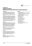
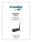
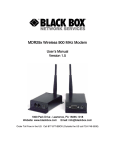
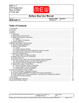
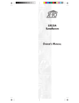
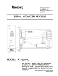
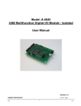
MDR220A-R2 Wireless 900 MHz Modem
User’s Manual
Version 1.0
1000 Park Drive - Lawrence, PA 15055-1018
Website: www.blackbox.com Email: [email protected]
Order Toll Free in the US: Call 877-877-BBOX (Outside the US call 724-746-5500)
Technical Support:
Phone: 877.877.BBOX
Outside US: 724.746.5500
Web: www.Black Box.com
Document Information
Copyright © 2008 Black Box, Inc. All rights reserved.
The information contained in this manual and the accompanying software programs are copyrighted and all rights are
reserved by Black Box, Inc. Black Box, Inc. reserves the right to make periodic modifications of this product without
obligation to notify any person or entity of such revision. Copying, duplicating, selling, or otherwise distributing any
part of this product or accompanying documentation/software without the prior consent of an authorized
representative of Black Box, Inc. is strictly prohibited.
All brands and product names in this publication are registered trademarks or trademarks of their respective holders.
This material is preliminary
Information furnished by Black Box in this specification is believed to be accurate. Devices sold by Black Box are
covered by the warranty and patent indemnification provisions appearing in its Terms of Sale only. Black Box makes
no warranty, express, statutory, and implied or by description, regarding the information set forth herein. Black Box
reserves the right to change specifications at any time and without notice.
Black Box’s products are intended for use in normal commercial and industrial applications. Applications requiring
unusual environmental requirements such as military, medical life-support or life-sustaining equipment are specifically
not recommended without additional testing for such application.
Limited Warranty, Disclaimer, Limitation of Liability
For a period of one (1) year from the date of purchase by the OEM customer, Black Box warrants the OEM transceiver
against defects in materials and workmanship. Black Box will not honor this warranty (and this warranty will be
automatically void) if there has been any (1) tampering, signs of tampering; 2) repair or attempt to repair by anyone
other than an Black Box authorized technician.
This warranty does not cover and Black Box will not be liable for, any damage or failure caused by misuse, abuse,
acts of God, accidents, electrical irregularity, or other causes beyond Black Box’s control, or claim by other than the
original purchaser.
In no event shall Black Box be responsible or liable for any damages arising: From the use of product; From the loss
of use, revenue or profit of the product; or As a result of any event, circumstance, action, or abuse beyond the control
of Black Box, whether such damages be direct, indirect, consequential, special or otherwise and whether such
damages are incurred by the person to whom this warranty extends or third party.
If, after inspection, Black Box determines that there is a defect, Black Box will repair or replace the OEM transceiver at
their discretion. If the product is replaced, it may be a new or refurbished product.
Revision History
Revision
Description
Version 1.0
1/3/08 - Initial Release Version
C o n te n ts
MDR220A-R2 RF Transceiver 1
Overview 1
Specifications 2
Hardware Interface 3
Configuration Utility 4
Overview 4
Software Installation 4
PC Settings Page 5
Port1/Port2 Options 6
Other Options 6
Status Bar 7
About Button 7
Configure Page 8
Read Radio Button 8
Write Radio Button 9
Show Defaults Button 9
Pairing Button 9
Load / Save to File Buttons 9
Port 1/Port 2 Buttons 10
Hex/Decimal Button 10
Terminal/Chat Page 11
Send Button 11
Hexadecimal / ASCII Display 11
Range Test Page 12
Test Selection 12
Transmit Packet Selection 13
Test Type 13
Receive Packet Display 13
Device Setup 14
Windows Modem Setup & Configuration 14
Auto-answer Feature 19
Enable Auto-Answer on the MDR220A-R2 20
Enable DTR On 20
Save the Auto-Answer configuration to a modem Profile, 0 or 1. 20
Recall Profile Settings 20
Connecting to a Non-PC Device 20
Troubleshooting 20
MDR220A-R2 RF T RANSCEIVER
1
Black Box’s new MDR220A-R2 RF transceiver is a Frequency-Hopping Spread Spectrum (FHSS) radio designed for
license free operation in the 900 MHz ISM band. Requiring no additional FCC licensing in the Americas, OEMs can
easily make existing systems wireless with little or no RF expertise. The MDR220A-R2 and MDR221A-R2 products
provide a wireless point-to-point connection between an RS232 device and a 56k data/fax modem.
OVERVIEW
This document contains information about the hardware and software interface between a MDR220A-R2 transceiver
and an OEM Host. Information includes the theory of operation, specifications, interface definitions, configuration
information and mechanical drawings.
Note: Unless mentioned specifically by name, the MDR220A-R2 will be referred to as "radio" or "transceiver".
Individual naming is used to differentiate product specific features. The host (PC/Microcontroller/Any device to which
the MDR220A-R2 is connected) will be referred to as "OEM Host" or “Host.”
2
S PECIFICATIONS
Table 1: ConnexNet Specifications
General
Interface Connector
Dual RJ-11 jack
RF Connector
RPSMA (Reverse polarity SMA) jack
Impedance
50 ohms unbalanced
Channels
32 (USA/Canada), 7 (Australia)
Security
One byte System ID. 56-bit DES encryption key.
Interface Buffer Size
Input/Output: 256 bytes
Transceiver
Frequency Band
902 - 928 MHz (USA/Canada); 915 - 928 MHz (Australia)
RF Data Rate (Raw)
76.8 kbps
RF Technology
Frequency Hopping Spread Spectrum (FHSS)
Output Power EIRP (3dBi gain antenna)
1000 mW
Supply Voltage
7 - 25 VDC
Current Draw (mA)
TBD
Sensitivity
-99dBm
Range, Line of Site (based on 3dBi gain antenna)
Up to 20 miles
Environmental
Temperature (Operating)
-40°C to 85°C
Physical
Dimensions
4.4” x 2.7” x 1.4”
Certifications
FCC Part 15.247
KQLAC4490
Industry Canada (IC)
2268C-AC44901000
3
H ARDWARE I NTERFACE
Table 2: Status LED descriptions
Status LEDs
RPSMA Antenna Connector
Pwr Link Rx
LED
Color
Description
Power
Green
On indicates that the unit is powered
up.
Link
Red
On indicates that the Client unit(s)
and Server unit are in Range of each
other. Client unit activates the Link
LED when in range of the Server
unit. Always lit on a Server unit.
RXD
Green
When flashing, indicates that the
device is receiving data.
TXD
Red
When flashing, indicates that the
device is transmitting data.
Tx
C ONFIGURATION U TILITY
4
OVERVIEW
Black Box provides an easy to use Configuration utility to program and test the device. The GUI based software is
compatible with Microsoft® Windows 95, 98, 2000, ME, NT, & XP.
SOFTWARE INSTALLATION
Locate the OEM software folder on the Black Box Tools & Literature CD and install the development kit software. To
install the software, run Setup.exe and follow the installation prompts. During the installation, the software will prompt
the user to install the Black Box USB Driver. It is recommended that the user installs the driver at the same time as the
software.
Note: The USB driver is only required for Black Box devices with a USB interface and is not required by the MDR220AR2 transceiver.
The installer will notify the user when the software has successfully been installed. The user may be prompted to
reboot the PC to complete the installation.
Click OK to complete the installation. By default, the software is stored in the following location on the Start Menu:
Start -> All Programs -> Black Box Network Services -> Black Box Config
CONFIGURATION UTILITY
PC SETTINGS PAGE
The PC Settings page is shown below, as it will appear the first time the program is run.
The first time the software is run, it will prompt you to select a product. Select the correct product in the Product pulldown menu. Doing this will automatically select the default baud rate for that particular transceiver. If the COM port is
listed as unavailable, a different COM port can be selected in the Port pull-down menu. The software can use two
serial ports if the Enabled: box is checked.
5
6
CONFIGURATION UTILITY
Port1/Port2 Options
The software can control up to (2) COM ports or TCP/IP ports, including virtual COM ports, which physically map to
USB or Ethernet ports. An error message will be displayed if a port is selected that is either nonexistent or already
occupied by another software program. When a port selection is made, the software will attempt to open the port and
list its status as; Unavailable, Open or Closed. Although menus are shown for Data Bits, Parity and Stop Bits, only the
Parity menu selection can be changed.
USB/COM PORT
Select this if you are using a standard COM port or have setup the ConnexNet as a Virtual COM Port.
TCP/IP PORT
Select this is you are connecting to the ConnexNet using a TCP/IP socket (default configuration).
Note: The port field must be set to 2101.
FIND PORTS BUTTON
If the available COM ports / IP addresses are unknown, the Find Ports button can be pressed to update the Port
Selection pull-down menu with all available COM ports / IP addresses.
HANDSHAKING
By default the OEM utility will use hardware handshaking and monitor the CTS/RTS lines. For cases where these lines
are not readily available such as RS-485 communications, the handshaking can be disabled by selecting “None” from
the dropdown box.
Note: Handshaking box does not appear when TCP/IP Port is selected.
Other Options
These are additional options that can be enabled.
SAVE SETTINGS ON EXIT
When enabled, all changes made to the Settings page will be automatically loaded the next time the software is run.
Otherwise, the changes will be discarded.
READ/WRITE WITH AT COMMANDS
When enabled, the software will use AT Commands for its read/write EEPROM functions instead of the standard
configuration commands. This box should be enabled at all times.
AUTO BAUD
When enabled, the software will scan all available COM Ports using the most common baud rates, until a radio is
found. If no radio is found or the software cannot open the port, an error message will be reported. The software will
only use Auto Baud when prompted by the user after an unsuccessful write process. To cancel the Auto Baud
process, press the ESC key.
Note: Auto Baud feature does not work when TCP/IP Port is selected.
AUTO ARCHIVE EEPROM SETTINGS
When enabled, the software will archive the EEPROM settings for each radio after a successful write process.
Although not required, the software will prompt the user to type a description of the changes made. Auto Archive can
be used to restore the radio to a previously known working configuration. The first time that a radio is read with Auto
Archive enabled will be stored as the “Original Configuration Settings” with the date and time the record was created.
MONITOR UDP FOR NEW DEVICES
When enabled, the software will automatically listen for new ConnexNet devices using the UDP port and automatically
add them to the Port Selection dropdown.
CONFIGURATION UTILITY
Status Bar
Located at the bottom of the software, the status bar gives the state of Port 1, RTS Port 1, CTS Port 1, Port 2, RTS Port
2, and CTS Port 2 lines. When the text appears black, the current state will be shown. When the text appears gray,
the current state will not be shown. The text shown in the bottom status bar gives a simplified status of the current,
pending software process. The software has no pending process when “Communications Idle” is shown.
About Button
The About button can be pressed to determine the revision number of the software and the contact information for
Black Box. Please include the software revision number in any correspondence with Technical Support.
7
8
CONFIGURATION UTILITY
CONFIGURE PAGE
The Configure page is a GUI representation of the 256 byte EEPROM contents within the radio. The same data is
shown in a full hexadecimal dump of the EEPROM in the EEPROM Editor View. The Configure page is shown below,
as it will appear until a radio is successfully read:
There are five sections on the Configure page; Radio Interface, Radio RF, Radio Features, Radio Other, and Info
Center. The fields displayed in these sections vary depending on the Product Mode. The Info Center provides a
quick description of each setting/mode. For detailed decriptions of the individual settings, please refer to the OEM
Module user’s manual.
Read Radio Button
To update the Configure and EEPROM Editor View pages with the EEPROM contents of a radio you are currently
connected to, click the Read Radio button. An example of the Configure page after a transceiver has successfully
been read is shown below:
CONFIGURATION UTILITY
Write Radio Button
After making changes to the controls on the Configure page, the Write Radio button can be pressed to save those
changes to the radio EEPROM. The user will be notified of a successful write with a “Write successful” prompt. If Auto
Archive is enabled, the software will prompt the user to type a description of the changes made.
Show Defaults Button
When the Show Defualts button is pressed, the GUI view will be updated with the default settings for the selected
product. This feature is only available on the GUI Page and will not work when using the EEPROM Editor View.
Pairing Button
The pairing button can be used to pair (address) two radios together. The two radios must both be connected to the
PC and to the Ports specified on the PC Settings page. The pairing function sets one radio as a Server and the other
as a Client and programs each radio’s Destination Address with the other radio’s MAC Address.
Load / Save to File Buttons
A file previously created by this software can be loaded to restore an EEPROM to a former state. Files of type *.TXT
and *.EE can be loaded.
9
10
CONFIGURATION UTILITY
An EEPROM can be saved to a file using the Save to File button. This allows for the current state of the EEPROM to
be restored at a later time.
Port 1/Port 2 Buttons
When Port 1 is depressed, the Write Radio and Read Radio buttons communicate through Port 1. When Port 2 is
depressed, the Write Radio and Read Radio buttons communicate through Port 2.
Hex/Decimal Button
All of the text entry type boxes found on the Configure page have a button located to the right of the box. When
pressed a menu will be shown which allows the selection of either Hexadecimal or Decimal numbering format for that
particular text box.
CONFIGURATION UTILITY
TERMINAL/CHAT PAGE
The Terminal/Chat page is a terminal emulator (similar to HyperTerminal) used to send small data packets between
two COM ports. As data is received it is appended to the appropriate Port window. An example of the Terminal/Chat
page is shown below.
Send Button
This button sends the data in the textbox out the selected port(s). The current user’s Windows username is also sent
over the RF with the data.
Hexadecimal / ASCII Display
New received data will be displayed in ASCII or Hexadecimal format; depending on the current setting.
11
12
CONFIGURATION UTILITY
RANGE TEST PAGE
The Range Test page allows packets of data to be sent between two radios and reports the numbers of successes
and errors.
Test Selection
There are six test options that can be selected. There are three typical hardware setups.
1
One radio is plugged into a serial or USB port on a PC. The second radio is plugged into a
separate power supply with a loopback adapter connected.
2
One radio is plugged into a serial or USB port on a PC. The other radio is plugged into a
different serial or USB port on the same computer.
3
One radio is plugged into a serial or USB port on a PC. The other radio is connected to a serial
or USB port on another PC.
CONFIGURATION UTILITY
If using two PCs for the test, the software run on both sides should have the second COM port disabled on the
Settings page.
Table 3: Test Selection Settings
Test Selection
Port 1 Action
Port 2 Action
Hardware Setup
Port 1 -> Port 2
TX
RX
2
Port 2 -> Port 1
RX
TX
2
Port 1 <-> Port 2
TX/RX
TX/RX
2
Port 1 Send Only
TX
N/A
3
Port 1 Receive Only
RX
N/A
3
Port 1 Loopback
TX/RX
N/A
1
Transmit Packet Selection
This section allows you to select the data packet used to perform the Range Test. You may either create data of a
specified byte length or load your own text or configuration file.
Test Type
The test type allows you to select how long the test will be performed.
Table 4: Test Type
Test Type
Description
Continuous
Test will run until stopped.
Timed
Test will run for a specified time period
Number of Runs
Test will run for a specified number of runs
Single Step
Test will run for a single step.
Break on Error
Test will run until an error occurs
Receive Packet Display
This section allows you to select how the received packets will be displayed. Received packets can either be
displayed in ASCII or Hexadecimal format, marked with a time stamp, and show only when an error has occurred.
13
D EVICE S ETUP
5
WINDOWS MODEM SETUP & CONFIGURATION
When connecting the MDR220A-R2 to a computer running Windows 95, 98, Me, 2000, or NT, the correct modem
driver must be installed and properly configured. Please follow the steps and diagrams below to complete the setup
and configuration.
1
2
Double-click on My Computer on the desktop, double-click on Control Panel, double-click
Modems to display the Modems Properties window.
If the Standard 56000 bps K56Flex Modem is not installed, click Add… to install a new modem.
DEVICE SETUP
3
Select Other when asked what type of modem you want to install, then click on Next>.
4
Select "Don't detect my modem; I will select it from a list". Then select Next>.
15
16
DEVICE SETUP
5
Select "(Standard Modem Types)" from the Manufacturers list, then select "Standard 56000 bps
K56Flex Modem" from the Models list. Click Next> to continue.
6
Select the port to use with the modem and click Next> to continue.
DEVICE SETUP
7
Wait while Windows installs the modem. Click Finish to complete the installation of the new
modem and to return to the Modems Properties window.
8
You are now ready to configure the new modem. Select "Standard 56000 bps K56Flex Modem"
and then click Properties.
17
18
DEVICE SETUP
9
On the General tab, select the port that is connected to the MDR221A-R2 unit. Select 115200 for
the Maximum speed. Do not select "Only connect at this speed", as this will not allow
communications from the MDR221A-R2 unit to the MDR220A-R2 unit.
10 Click the Connection tab. Select 8 Data bits, None for Parity, 1 for Stop bits. Select "Wait for dial
tone before dialing". Selecting "Cancel the call if not connected within xx secs" is optional.
DEVICE SETUP
11 Click Advanced… to continue. Select "Use flow control" and then select "Hardware (RTS/CTS)".
Click OK to return to the Standard 56000 bps K56Flex Modem Properties window. Click OK to
return to the Modems Properties window. Click Close to complete the configuration.
AUTO-ANSWER FEATURE
This feature enables the MDR220A-R2 unit to answer an incoming call over the phone line. In order to enable this
feature, the HyperTerminal program must be opened. HyperTerminal is launched by clicking on the Start icon in
Windows and selecting Programs. From the Programs list select Accessories, Communications, then HyperTerminal.
Once in HyperTerminal, you must type a name for the connection and click OK. Next to the Connect Using field, select
the proper COM Port. Make sure the Baud Rate setting is equal to the MDR221A-R2’s Baud Rate setting, Data Bits
19
20
DEVICE SETUP
equals 8, Parity equals None, Stop Bits Equals 1, and Flow Control equals Hardware. Apply the settings and
HyperTerminal is ready to send commands.
MDR220A-R2 configuration: Broadcast, Modem Control and RTS should be enabled.
MDR221A-R2 should be configured with default values and Auto Destination enabled.
Make sure Auto-Answer is enabled on the MDR220A-R2: (Refer to RC56D ATCRM.PDF for the AT Commands)
Enable Auto-Answer on the MDR220A-R2
• Connect the MDR221A-R2 to a computer and start HyperTerminal.
• Type the characters ATS0 = n command, where n = the number of rings to Auto-Answer.
This command sets the S0 parameter to a value other than zero to enable Auto-Answer. S0
sets the number of rings required before the modem automatically answers a call. Setting this
parameter to zero disables auto-answer mode.
Enable DTR On
• Send the AT&D0 command
Save the Auto-Answer configuration to a modem Profile, 0 or 1.
• Send the AT&Wn command, where n = Profile number.
Recall Profile Settings
• Send the AT&Yn to command or ATZn command (where n = Profile number) to recall the
Profile settings. ATZn performs a Soft Reset and Restores Profile n. AT&Yn Designates a
Default Reset Profile, which will be used after a hard reset.
The modem is now ready to answer a phone call automatically.
Connect to the MDR220A-R2 using a computer or another telecom Host. Once connected, multiple MDR221A-R2
units can communicate with the MDR220A-R2.
CONNECTING TO A NON-PC DEVICE
When using MDR220A-R2 to connect a non-PC device to a phone line, it is important that the MDR221A-R2 unit is
configured properly. The MDR221A-R2 unit must match the serial settings of the non-PC host device
To configure the MDR221A-R2 unit, refer to the MDR221A-R2 User’s Manual located on the Black Box CD or website.
The MDR220A-R2 unit cannot be reconfigured except by Black Box.
TROUBLESHOOTING
Technical Support is available Monday through Friday 8:30 - 5:00.
DEVICE SETUP
Please include the following in all correspondence with Technical Support: company name, phone number, product
part number, a good description of the problem or question, and the EEPROM files for both radios.
To save the EEPROM files, read the radio using the Configure page and then press the Save to File button. Attach
both files to the email. Visit us online www.Black Box.com.
21