1
Contents
Introduction
An Overview of MAS Software .................................................................................................................1-1
Software Integration
..........................................................................................................................1-1
Central Station System: The Big Picture....................................................................................................1-3
Hardware
..........................................................................................................................1-3
Software
..........................................................................................................................1-4
Signal Processing..........................................................................................................................1-5
Getting Started
Before You Begin.........................................................................................................................2-1
What You'll be Learning...............................................................................................................2-1
Using the Terminal .......................................................................................................................2-2
Conventions
..........................................................................................................................2-3
Signing on
..........................................................................................................................2-5
Signing Onto an AOS/VS-Based System ........................................................................2-5
Signing Onto a UNIX-Based System ..............................................................................2-6
Signing Onto a PC-Based System ...................................................................................2-7
Menu and Working Screens..........................................................................................................2-8
Menu Screens..................................................................................................................2-8
Working Screens.............................................................................................................2-9
Moving to Another Screen ..............................................................................................2-9
Moving From Field to Field ............................................................................................2-10
Entering Data
..........................................................................................................................2-11
Entering Dates.................................................................................................................2-11
Entering Times................................................................................................................2-11
Editing Data
..........................................................................................................................2-12
Recalling an Account Number ......................................................................................................2-12
Printing Reports ..........................................................................................................................2-13
Interrupting a Print Job....................................................................................................2-14
Saving Data
..........................................................................................................................2-15
Signing Off
..........................................................................................................................2-15
Signing Off From the CS Exit Menu...............................................................................2-15
Signing Off From Other Screens .....................................................................................2-15
Accessing the System for On-Line Support (SOS)........................................................................2-16
Summary of Frequently Used Commands.....................................................................................2-16
Summary
..........................................................................................................................2-16
Setting up Your CS System
Before You Begin.........................................................................................................................3-1
What You'll be Learning...............................................................................................................3-1
Overview
..........................................................................................................................3-2
Setting up Codes for Commonly Shared Subscriber Information ..................................................3-2
Screen 11: Common Overflow Maintenance...................................................................3-3
Screen 54: Installer Update .............................................................................................3-6
Screen 52: Agency Update ..............................................................................................3-10
Grouping Activity for Summary Reporting...................................................................................3-13
Defining Monthly Reporting Periods ............................................................................................3-14
Setting up Event Codes.................................................................................................................3-15
Deleting Event Codes......................................................................................................3-25
Assigning Event Codes to Function Keys .......................................................................3-25
Setting up Locations and Partitions...............................................................................................3-26
Setting up Locations........................................................................................................3-27
Multiple Location Switching.........................................................................................................3-29
Multi-MAS (Database Partitioning) ..............................................................................................3-31
Controlling Alarms "Sent" to the Alarm Dispatch Screen .............................................................3-35
Setting up On-Test Categories ......................................................................................................3-37
Daylight Savings Time Control.....................................................................................................3-38
Understanding the Control File.....................................................................................................3-40
Summary
..........................................................................................................................3-55
Summary of Commands Used in This Section..............................................................................3-55
Setting up Subscriber Accounts
Before You Begin.........................................................................................................................4-1
What You'll be Learning...............................................................................................................4-1
Overview
..........................................................................................................................4-2
Setting up Basic Subscriber Information.......................................................................................4-3
Defining Mandatory & Optional Data Entry Fields.......................................................................4-16
Copying Individual Accounts From Billing Receivables to CS.....................................................4-17
Copying Account Information From One CS Account to Another................................................4-18
Defining the Event Which may Occur at the Subscriber's Site ......................................................4-20
Defining Mandatory & Optional Data Entry Fields.......................................................................4-26
Listing Individuals to be Contacted for Alarms.............................................................................4-27
Preparing Your CS Software for Passcards .....................................................................4-27
Setting up Passcard Privileges.........................................................................................4-31
Setting up Subscriber Passcards ......................................................................................4-32
Setting up Installer, Employee, or Third Party Passcards.................................................4-37
Printing Passcards ...........................................................................................................4-39
Listing Instructions for Handling Alarms......................................................................................4-43
Setting up Additonal Information Pages .......................................................................................4-50
Assigning Common Overflow to an Account..................................................................4-51
Setting up Overflow Information.....................................................................................4-53
Reporting Changes to Account Information..................................................................................4-54
Summary
..........................................................................................................................4-56
Summary of Commands Used in This Section..............................................................................4-61
Basic Monitoring
Before You Begin.........................................................................................................................5-1
What You'll be Learning...............................................................................................................5-1
Overview
..........................................................................................................................5-2
Reviewing a List of Alarms ..........................................................................................................5-3
Warning Messages ..........................................................................................................5-6
Dispatching for an Alarm Signal...................................................................................................5-7
Accessing an Alarm on the Alarm Dispatch Screen ......................................................................5-8
Reviewing the Alarm and Account Information............................................................................5-10
Subscriber Information....................................................................................................5-11
Installer Information........................................................................................................5-12
Dispatch Instructions and Account Overflow Information...............................................5-13
Using Commands to View Dispatch Instructions & Overflow ........................................5-17
Account History..............................................................................................................5-19
Account Status ................................................................................................................5-19
Calling Individuals to Respond to an Alarm..................................................................................5-20
Autodialing with Function Keys......................................................................................5-21
Autodialing Using the P'hone Commands .......................................................................5-22
Autodialing From Dispatch Instructions or Overflow......................................................5-23
Autodialing From Installer Text ......................................................................................5-24
Displaying and Autodialing From Call Lists ...................................................................5-25
Autodialing From Common Overflow ............................................................................5-30
Autodialing From the Passcard Lookup Window ............................................................5-32
Autodialing From the Agency Lookup Window..............................................................5-33
Recording Information to the Subscriber's History........................................................................5-34
Logging Event/Resolution Codes ....................................................................................5-35
Entering Lengthy Comments into Subscriber History .....................................................5-37
Reviewing Additional Information ...............................................................................................5-39
Reviewing a Subscriber's Payment Status .......................................................................5-40
Reviewing Subscriber Information..................................................................................5-43
Reviewing a Subscriber's CS History ..............................................................................5-44
Reviewing a List of Zones...............................................................................................5-45
Reviewing the Status of Zones and Schedules.................................................................5-48
Main Menu Screens ......................................................................................................................5-49
Looking up a Subscriber's Account Number ...................................................................5-50
Checking on Outstanding Follow-up Messages...............................................................5-51
Reviewing Accounts Which Have Been Placed On-test..................................................5-53
Listing Accounts Placed on Runaway .............................................................................5-55
Checking on Screens and Accounts in Use......................................................................5-57
Looking up Passcards for a Subscriber's Account............................................................5-58
Looking up the Account for a Passcode ..........................................................................5-60
Looking up all Accounts for a Master Passcode ..............................................................5-62
Summary
..........................................................................................................................5-63
Summary of Commands Used in This Section..............................................................................5-63
Special Monitoring Features
Overview
..........................................................................................................................6-1
Placing an Account In or Out of Service.......................................................................................6-2
Preparing the CS System for this Feature ........................................................................6-2
Setting p Out of Service Categories.................................................................................6-3
Placing an Account Out of Service..................................................................................6-4
Placing an Account Back into Service.............................................................................6-5
Placing a Group of Accounts Into or Out of Service........................................................6-5
Printing a List of Out of Service Accounts ......................................................................6-6
Secondary Transmitters ................................................................................................................6-7
Setting up Accounts with Secondary Transmitters ..........................................................6-7
Processing Signals for Systems with Secondary Transmitters .........................................6-7
Reviewing Problems for Redundant Alarm Systems .......................................................6-8
Resolving Signal Redundancy Errors for Redundant Alarm Systems ..............................6-8
Permits for Dispatching ................................................................................................................6-9
Preparing Your CS Software for Permits.........................................................................6-9
Setting up Permits ...........................................................................................................6-11
Dispatching for Agencies Requiring Permits...................................................................6-15
Displaying False Alarm History......................................................................................6-17
Cross Referencing Permits ..............................................................................................6-18
Updating Permit Statuses and Trakcing False Dispatches ...............................................6-19
Schedules and Late Event Processing ...........................................................................................6-21
Preparing Your CS System for Schedules & Late Event Processing................................6-22
Setting up a Subscriber's Schedule ..................................................................................6-23
Default Opening/Closing Windows.................................................................................6-29
Setting up Holiday Schedules..........................................................................................6-31
Monitoring Supervised Accounts ....................................................................................6-34
Processing Irregular and Late Events ..............................................................................6-39
Reporting for Late Events and Supervised Accounts.......................................................6-40
Repairing Expected Events .............................................................................................6-40
Scheduling Timer Tests...................................................................................................6-41
Designating a Mailing Address for Reports ..................................................................................6-42
Alternate IDs
..........................................................................................................................6-44
Subsites
..........................................................................................................................6-47
Setting up Subsites ..........................................................................................................6-47
Monitoring Master Accounts and Subsites ......................................................................6-49
Cross-refereicing Master Sites and Subsites ....................................................................6-50
Merging Subaccount and Master Account History ..........................................................6-52
Specialized Alarm Monitoring Screens.........................................................................................6-53
Summary
..........................................................................................................................6-56
Summary of Commands Used in This Section..............................................................................6-56
Using Event Codes & Function Keys
Overview
..........................................................................................................................7-1
Entering Event Codes ...................................................................................................................7-3
Passive Event Codes .....................................................................................................................7-5
Dispatching the Police.....................................................................................................7-5
Dispatching the Fire Department.....................................................................................7-5
Dispatching a Guard........................................................................................................7-6
Canceling a Dispatch.......................................................................................................7-6
Calling the Premise or Alarm Company..........................................................................7-6
Verified False Alarms .....................................................................................................7-7
Active Event Codes ......................................................................................................................7-8
Partially Clearing an Alarm.............................................................................................7-8
Partial Clear.......................................................................................................7-8
Partial Clear with Auto Minutes ........................................................................7-11
Fully Clearing an Alarm..................................................................................................7-13
Runaway.........................................................................................................................7-16
Placing a Zone on Runaway ..............................................................................7-16
Clearing a Runaway Zone .................................................................................7-18
Placing or Removing a Group of Accounts on Runaway...................................7-19
Reviewing Accounts Which have been Placed on Runaway..............................7-20
On Test .............................................................................................................7-21
Placing an Account on Test ...............................................................................7-21
Placing a Zone Group on Test ...........................................................................7-24
Placing a Zone Group Exception List on Test....................................................7-24
Placing an Exception List on Test......................................................................7-25
Extending a Test................................................................................................7-26
Changing the List of Zones on Test ...................................................................7-26
Clearing a Zone From Test ................................................................................7-27
Resetting the Trip Counter.................................................................................7-28
Placing Zones On and Off Test from Screen 3...................................................7-29
Reviewing Accounts Which have been Placed on Test......................................7-31
Follow-up Messages .......................................................................................................7-32
Creating a Follow-up Message ..........................................................................7-32
Rescheduling a Follow-up Message ..................................................................7-34
Clearing a Follow-up Message ..........................................................................7-35
Check on Outstanding Follow-up Events...........................................................7-36
Clearing Irregular and Late Events..................................................................................7-37
Processing Irregular Openings ...........................................................................7-37
Processing Late Openings..................................................................................7-40
Processing Late Closes ......................................................................................7-42
Making One-Time Only Changes to a Schedule ................................................7-45
Processing Late Timer Tests..............................................................................7-48
Clearing a Redundancy Error for Secondary Transmitters...............................................7-49
Creating Service or Guard Tickets ..................................................................................7-50
Assigning Event Codes to Function Keys .......................................................................7-52
Autodial-Related Function Keys .....................................................................................7-52
Reporting
Overview
..........................................................................................................................8-1
Screen 21: CS Account Database Printout ..................................................................................8-3
Screen 23: Daily Alarm Printout .................................................................................................8-5
Screen 24: Supervised Account Mail-Out Reports ......................................................................8-7
Screen 25: CS Short Printout ......................................................................................................8-12
Screen 26: Late Event Report .....................................................................................................8-14
Screen 27: Common Overflow Printout ......................................................................................8-16
Screen 71: Event Code Printout ..................................................................................................8-18
Screen 72: Agency Code Printout ...............................................................................................8-18
Screen 74: Installer File Printout.................................................................................................8-19
Screen 75: CRT Default Printout ................................................................................................8-20
Screen 76: Holiday File Printout .................................................................................................8-21
Screen 118: Monthly Summary View ..........................................................................................8-22
Screen 140: Updated CS Account Database Printout ...................................................................8-23
Screen 141: CS Event Code Search .............................................................................................8-25
Screen 181: Account Usage Report..............................................................................................8-26
Screen 201: Short Print by Install Date ........................................................................................8-27
Screen 202: Short Printout by Misc. Sorting ................................................................................8-28
Screen 204: Excessive Activity Report ........................................................................................8-31
Screen 205: Combined Activity Report........................................................................................8-33
Screen 210: Summary Activity Report.........................................................................................8-36
Screen 211: Shift Acitity Report ..................................................................................................8-38
Screen 212: Late Events by Location ...........................................................................................8-41
Screen 221: History Tape Printout ...............................................................................................8-42
Screen 222: Detailed Activity Printout by Installer ......................................................................8-45
Screen 231: Expected Event Printout ...........................................................................................8-48
Screen 235: Zone Restoral Required Report ................................................................................8-49
Screen 236: Port Usage Report ....................................................................................................8-50
Screen 244: User Profile Maintenance .........................................................................................8-51
Screen 247: Dispatch/Overflow Search Printout ..........................................................................8-52
Screen 251: File Update Log Printout ..........................................................................................8-53
Screen 261: CS Non-Activity Report...........................................................................................8-54
Screen 262: No Expected Event Report .......................................................................................8-55
Screen 264: Location or Area Code Report..................................................................................8-57
Screen 270: Account Assignment Status Report ..........................................................................8-58
Screen 276: Special Alarm Printout by Resolution Code Ranges.................................................8-59
Screen 277: Passcard Report........................................................................................................8-61
Screen 278: Full Clear Without Operator Action Report..............................................................8-62
Screen 279: Receiver Error Acknowledgement Report ................................................................8-63
Screen 281: Customer File Report ...............................................................................................8-64
Screen 282: Out of Service/On Test Account Listing...................................................................8-67
Screen 283: False Dispatch Tracking Report ...............................................................................8-69
Screen 286: Special Alarm Printout by Resolution Code Ranges.................................................8-71
Reporting, continued
Screen 290: Non-Active Event Code Printout ..............................................................................8-73
Screen 292: Operator Activity Printout ........................................................................................8-74
Screen 295: Daily Event Count Printout ......................................................................................8-75
Screen 297: Disposition by Account Report.................................................................................8-76
Screen 298: Operator Statistics Report.........................................................................................8-77
Screen 299: Dispatch Action Report ............................................................................................8-79
Summary of Commands Used in This Section..............................................................................8-82
Maintaining Your CS System
What You'll be Learning...............................................................................................................9-1
Monthly Procedures......................................................................................................................9-3
Posting Event History ...................................................................................................................9-4
Copying Event History to Tape.....................................................................................................9-6
Changing (Rolling) the Reporting Period......................................................................................9-8
Transferring Basic Subscriber Information to Tape.......................................................................9-9
Checking the Size of Your Data Files ...........................................................................................9-11
Rebuilding the Index Files ............................................................................................................9-13
Clearing Expired Dispatch Instructions and Irregular Schedules...................................................9-14
Deleting Accounts ........................................................................................................................9-15
Making an Account Deletion Request.............................................................................9-15
Purging a Deleted Account From the CS System ............................................................9-18
Reactivating a Deleted Account ......................................................................................9-20
Purging Event Activity .................................................................................................................9-21
Purging Cancelled Accounts.........................................................................................................9-23
Purging Event Date Indexes..........................................................................................................9-24
Deleting Dispatch Action Records................................................................................................9-25
Purging Agency Dipsatch Records ...............................................................................................9-26
Deleting Agency Information .......................................................................................................9-27
Changing Resolution Codes..........................................................................................................9-28
Changing the Installer Code for a Range of Accounts...................................................................9-30
Changing or Inserting an Area Code.............................................................................................9-31
Changing the Locations for a Range of Accounts .........................................................................9-41
Changing the Zones for a Range of Accounts ...............................................................................9-43
Assigning a New Account Number to an Existing Account ..........................................................9-44
Clearing a Block of Alarms ..........................................................................................................9-45
Setting up an Expected Event for Several CS Accounts................................................................9-47
Printing a Log of All Events .........................................................................................................9-49
Assigning a Block of Account Numbers to an Installer.................................................................9-50
Assigning ASCII Values to a CRT ...............................................................................................9-55
Access Security ..........................................................................................................................9-56
Summary of Commands Used in This Section..............................................................................9-62
Appendix A: Automatic Telephone Dialing..........................................................................A-1
Appendix B: Setting up & Controlling Receivers..............................................................B-1
Appendix C: File Repair Utilities ...............................................................................................C-1
Appendix D: Reserved Event Codes.......................................................................................D-1
Appendix E: Sample Reports .....................................................................................................E-1
Appendix F: Dispatching with the CS 5.40-Style Dispatch Screen...........................F-1
Preface
About the Central Station Instruction Manual
The Central Station Instruction Manual is a step-by-step guide for new users to setting up and
maintaining your Central Station (CS) software, and performing the daily tasks of receiving,
processing, and resolving alarm signals. This manual is divided into major sections based on the
functions performed by CS operators, supervisors, and managers using the CS system.
Section 1 - Introduction
This section gives a brief overview of how all Monitoring Automation System (MAS) software
works together. You'll also learn about some of the features available in the CS system. This section
should be read by all CS users.
Section 2 - Getting Started
Section 2 details:
•
•
•
•
•
Conventions used by this manual and by MAS software;
Signing on and off of the computer;
Moving through CS;
Entering and editing data;
Commands used for printing reports.
This section should be read by users new to MAS software.
Section 3 - Setting up Your CS System
Section 3 shows you how to set up the most basic information needed in order for your CS software
to work properly. This information includes:
•
•
•
•
Agencies
Installers
Locations
Reporting periods
This section should first be read by the CS supervisors who will decide how information will be
structured in the CS system. Then, the section may be used by data entry staff as a guide to entering
data.
Section 4 - Setting up Subscriber Accounts
This section describes how to set up and edit a basic subscriber account. This information includes:
•
The subscriber's name, address, and telephone numbers;
MAS Central Station, 5.50
Preface
•
•
•
•
•
•
The agencies which provide service to the subscriber's account
The type of alarm system used;
Zones monitored at the subscriber's site;
A schedule of times the subscriber's site will be opening and closing.
Instructions for calling the premise and dispatching agencies;
A list of individuals to be contacted when an alarm is tripped;
This section should first be read by the CS supervisors who will decide how information will be
structured in the CS system. Then, the section may be used by data entry staff and CS operators as a
guide to entering data and understanding what it means.
Section 5 - Basic Monitoring
The process of monitoring and retrieving basic alarm signals is detailed in this section. This section
should be read by CS operators and their supervisors.
Section 6 - Special Monitoring Features
While Sections 4 shows you how to set up a basic subscriber account and Section 5 shows you how
to use basic monitoring functions, Section 6 shows you how to set up and use the more advanced
features of the CS system. The advanced features allow you to offer special services to your
installers and subscribers. This section will show you how to set up permits, secondary transmitters,
and subsites. This section should be read by CS operators and their supervisors.
Section 7 - Using Event Codes and Function Keys
The first part of this section shows you how to use event codes to record information to a
subscriber's event history and to resolve alarm signals. The last part of the section shows how to
assign event codes to function keys for faster, easier signal processing. This section should be read
by CS operators and their supervisors.
Section 8 - Reporting
CS includes many reports which help you provide information to your subscribers and to analyze
CS activity. This section should be read by CS operators and their supervisors.
Section 9 - Maintaining Your CS System
This section describes two types of utility functions: monthly maintenance and file maintenance.
These utilities are used to perform tasks such as purging files that have become full, rebuilding
index files, and restricting user access. This section should be read by the system manager.
This manual also includes five appendices containing additional or reference information for some
of the CS features described above. The appendices are as follows:
Appendix A - Using the Autodialer
This appendix describes how to set up the software and hardware for the MAS Autodial module.
Preface
MAS Central Station, 5.50
Appendix B - Setting up and Using Receivers
This appendix describes the screens shown on the Signal Format/Manual Entry Menu and on the
Receiver Utility Menu. The screens shown on Signal Format/Manual Entry Menu are used to
process signals manually in the event that the your computer system fails. The screens shown on
the Receiver Utility Menu are used to set up and control your receivers.
Appendix C - File Repair Utilities
This appendix describes the screens shown on the File Repair Menu. These utilities are used to
repair information in your CS system if it is corrupted during a system failure. These utilities should
be used only on the advice of MAS.
Appendix D - Reserved Event Codes
This appendix lists the standard set of event codes provided to you by MAS.
Appendix E - Sample Reports
This appendix shows a sample of every report that may be printed from the CS system.
Related Documents
Other documents available from MAS that are related to the operation of your CS system include the
following:
•
•
•
Code Red Reference Manual
System Administration Manual
UL-Requirements for Central Stations
Other documents available from MAS that are related to systems which interface with your CS
system include the following:
•
•
•
•
•
•
Service System Instruction Manual
Billing/Receivables Instruction Manual
MASlink Host System User Manual
MASlink RPC System User Manual
VRT II Reference Manual
VRT Reference Manual
MAS Central Station, 5.50
Preface
Section 1 - Introduction
An Overview of MAS Software
Monitoring Automation Systems (MAS) has designed and produced several integrated software
packages tailored to meet the needs of the alarm industry. These software packages include: Central
Station, Billing/Receivables, the Service System, and Inventory Control. In addition, MAS has
created hardware and software packages which allow your service technicians, alarm dealers, and
subscribers communicate with your Central Station system. These communication packages include
VRT, VRT II, and MASlink.
The Central Station (CS) system allows alarm monitoring companies to automate the monitoring of
their subscribers' alarm signals and other defined events, such as openings, closings, timer tests,
troubles, or restorals. Each received signal is analyzed by the CS software to determine whether it is
a scheduled event (such as a normal weekday opening) or an unscheduled event (such as a hold-up
or unscheduled opening). Scheduled events are automatically logged to the appropriate subscriber's
account history. Alarms and irregular events are presented to the operator in a priority sequence.
Each subscriber's account represents only one alarm status; therefore, multiple trips or redundant
signals need to be handled only once, minimizing operator actions.
The heart of MAS signal monitoring is a dispatch screen that displays all the data that the operator
needs, such as subscriber information, local police and fire department numbers, and response
information to dispatch on alarms. All processing activity is handled on this dispatch screen using
autodial and function keys to minimize and standardize data entry. Upon the final resolution of the
event, you have a complete history of when the event occurred and the steps taken by the CS
operator to resolve it.
The Central Station system provides an extensive list of reports that you'll find useful in getting the
information you need to analyze your subscriber database and activity to make sound business
decisions.
Software Integration
MAS software packages are designed to work together. When you set up a new software package,
you'll find that you can transfer account information from MAS Billing/Receivables (B/R) to CS or
from CS to B/R. Account information may also be transferred from CS to the MAS Service System
(SS) software package. By transferring customer information between software packages, you
reduce the amount of time required to enter new accounts and ensure that no data entry errors are
made during the transfer.
MAS Central Station, 5.50
Introduction 1-1
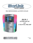
Additionally, these software packages work together as follows:
•
If you use MAS Billing/Receivables to bill dealers for monitoring their accounts, the
information included on the invoice is obtained partly from CS and partly from B/R.
•
If you use MAS Service System software, you may create service tickets in CS which
may be immediately handled by a service dispatcher.
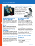
MAS software integration is illustrated in Figure 1-1.
Figure 1-1
>
Central Station
with Service
<
<
^
Accounts Payable
v
v
v
Billing/Receivables
Voice Response
Terminal II
MASlink
^
v
Inventory Control
^
v
General Ledger
In addition to being fully integrated, all MAS software packages have a common design for menus,
screens, and commands which makes it easy to switch from one package to another. For example, a
data entry clerk who knows how to create a customer account using CS or SS software will find it
easy to create a customer account using B/R software.
1-2 Introduction
MAS Central Station, 5.50
Central Station System: The Big Picture
When a new subscriber has an alarm system installed at his home or office (the site), he contracts not
only to have the alarm system hardware installed but also to have your central station monitor his
system's alarm signals. The alarm system hardware installed at the subscriber's site consists of the
following:
•
Sensing devices placed at various zones at the subscriber's site. A zone is a point-of-entry to
the site or an area that is to be protected. The most common types of sensing devices used to
protect an area are magnetic contacts, infrared motion detectors, and smoke detectors.
Business subscribers may have provided the Central Station with a schedule of its normal
business hours so that Central Station operators will be able to distinguish normal events,
such as openings or closings, from unexpected or emergency events, such as robbery or fire.
When an event takes place, the activated device generates a signal. This signal is sent to a
communicator.
•
A communicator (also called a transmitter or panel) is a transmitting device located at the
subscriber's premises. The communicator contains the chip number used to create the
subscriber's account number and is programmed with a phone number that dials a specific
receiver within the central station.
The communicator receives the signal from a zone. Once the signal has been received, the
communicator adds the programmed account number and reports the zone that has been
activated, the condition of that zone (alarm, trouble, restore) via telephone line or radio
waves to the receiver within the central station.
The hardware and software used at your central station to process alarm signals consists of the
following:
Hardware
A receiver is an electronic unit located in your central station and is connected to the telephone
system. The unit receives incoming alarm signals and sends them to the computer for processing.
Once the signal has been received and the information is validated, the receiver adds the date and
time the signal was received before sending it to the computer. The information sent to the
computer includes the date and time the signal was received, the receiver number, the line number
on which is was received, subscriber's chip number, zone violated, and condition of the zone.
MAS Central Station, 5.50
Introduction 1-3
Software
In the computer, the first place the signal goes is to the input program. The function of the input
program is to constantly check a specific receiver's port for incoming signals, receive and
acknowledge the reception of the signal, and send the signal to the ring file for that receiver.
The ring file is a holding file. The computer has a ring file for each receiver. Once the signal enters
the ring file it is processed by the output program, then it is removed from the ring file.
The output program unloads the signal from the assigned ring file. The output program rebuilds the
signal's account number to a format recognizable within the CS system. The account number will be
built based upon the format set up on the 954A, CS Receiver Format Entry Screen.
Once the account number has been built, the incoming signal, now referred to as an event, is
compared with the Zone-Event Code View Screen for the account. If the event code has a response
code of operator always, the account is placed into alarm status. If the event's response code is log
always, the event is placed directly into the account's history file. All other events are passed to the
autologger for processing.
The autologger checks the account's schedule and passcards, updates the expected events list, and,
based upon the results of these checks, the signal is either placed directly into the account's history
file or assigned a priority and passed to the operator for action. When an operator must take action
on an event, it is considered to be an alarm.
Alarm events are processed by operators according to priority. If all operators are busy, events are
displayed on a buffer screen in the order of their priorities so they may be handled by the next
available CS operator. When the operator has dealt with the event, he closes out the event by
logging a resolution code to the customer's history file which describes what he did to resolve the
event.
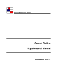
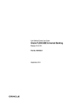
The following flowchart summarizes a signal's progress from beginning (at the zone) to resolution
(in the customer's history file).
1-4 Introduction
MAS Central Station, 5.50
Signal Processing
ZONE
v
COMMUNICATOR
SUBSCRIBERS PREMISES
SUBSCRIBERS PREMISES
v
RECEIVER
CENTRAL STATION
CENTRAL STATION
COMPUTER
v
INPUT PROGRAM
COMPUTER
v
RING FILE
v
OUTPUT PROGRAM
v
AUTOLOGGER
ZONE
SCHEDULE
EVENT CODE
PASSCARD
v
ALARM SCREEN
OPERATOR ACTION
v
HISTORY
v
>
MAS Central Station, 5.50
Introduction 1-5
Section 2 - Getting Started
Before You Begin
Before reading this section you should:
·
Read the "Introduction" of this manual.
·
Obtain your sign-on information from the System Manager.
What You'll be Learning
In this section you will learn:
•
To sign onto the system
•
The conventions used throughout this manual
•
The types of screens you'll see in the Central Station software
•
To move from screen to screen
•
To move the cursor from field to field
•
To enter data
•
To recall one of the last 10 account numbers used
•
To print reports
•
To enter a command at the command line
•
To save data
•
To sign off of the system
•
To access the System for On-Line Support (SOS)
MAS Central Station, 5.50
Getting Started 2-1
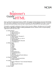
Using the Terminal
All the keys you'll use in your Central Station software are located on the main keypad and numeric
keypad areas of the keyboard, shown in Figure 2-1.
Figure 2-1
The main keypad is similar to that of a conventional typewriter; however, on Data General-style
keyboards, the [ALPHA LOCK] and [SHIFT] keys function in a slightly different way.
When you press the [ALPHA LOCK] key, the ALPHA LOCK light on your keypad is lit and each
letter you press is displayed in uppercase letters (A, B, C, etc.). Pressing the [ALPHA LOCK] key a
second time will turn the ALPHA LOCK light off and each letter you press is displayed in lowercase
letters (a, b, c, etc.).
The [ALPHA LOCK] key cannot be used to type special characters, such as the dollar sign ($) or the
percent sign (%). Instead, to access these characters, you must press the [SHIFT] key. The [SHIFT]
key may also be used, as on a conventional typewriter, to type a single uppercase letter.
On PC-style keyboards, the [CAPS LOCK] key functions in the same way as the [ALPHA LOCK]
key.
Another key you'll frequently use is the [NEW LINE] key for DG systems or the [ENTER] key for PC
systems. The [NEW LINE] or [ENTER] key is used to enter data and commands or to move from
field to field.
In addition to the [ALPHA LOCK], [SHIFT], and [NEW LINE] keys, you'll also be using the
alphabetic (A, B, C, etc.) and numeric (1, 2, 3, etc.) characters. Other keyboard characters that you'll
use are the comma (,), semicolon (;), period (.), underscore (_), and the backslash (\).
In addition to the ALPHA LOCK light, Data General keyboards will also have another light called
the ON LINE light. If it is not lit, anything you type on your keyboard will appear on the screen but
any data or commands you type will not be transmitted to the main computer. To turn the light on,
hold down the [CMD] key and press the [ON LINE] key at the same time.
Getting Started 2-2
MAS Central Station, 5.50
Conventions
As you look through this manual you'll notice the terms, "type," "press," and "enter." Each term has
its own meaning. In addition, screen messages and special notes are presented in a specific way.
The following section describes the conventions used throughout this manual.
·
Enter XXX
Type the bold characters shown and then press [NEW LINE]
or, for PC-style keyboards, press [ENTER].
Example: Enter S
·
Type
XXX
Type the bold characters shown.
Example: Type CONFIRM
·
Press [XXX]
Press the key described by the brackets.
Example: Press [NEW LINE]
·
Hold [XXX] X
When you see the "Hold" instruction, hold down the first key
shown, while pressing the second key.
Example: Hold [Ctrl] Q
·
SCREEN MESSAGE
Messages that may appear on your screen are shown in italic
type.
Example: PASSWORD
·
<xxx>
Variable information that is displayed on the screen, or
should be typed at the keyboard, is shown lowercase in angle
brackets. Information about the variable is included within
the brackets.
Example: LAST MONTH PURGED WAS <month>
·
Warning:
Note:
MAS Central Station, 5.50
Warnings and other important notes are presented in bold as
shown.
Getting Started 2-3
Apart from the terms listed above, there are a few more points that should be carefully noted before
you begin to use this manual.
·
Do not confuse the numeral zero (0) with the capital letter O. The computer assigns a
different meaning to each of these characters.
·
Similarly, the number one (1) should not be confused with the lowercase letter (L). Use only
uppercase letters to enter commands, such as D for D'ELETE. Both upper- and lowercase
letters may be used to enter information in a field.
·
Most of the procedures in this manual should be performed on a user terminal. If a
procedure requires that you use the master terminal or system console, it will be clearly
stated.
Getting Started 2-4
MAS Central Station, 5.50
Signing On
The Central Station software package may be used on several different types of computers. The way
you sign onto each type of computer and the messages you'll see are different for each type of
system. The following sections show you how to sign onto three basic system types:
•
•
•
AOS/VS-based systems
UNIX-based systems
PC-based systems
Signing Onto an AOS/VS-Based System
To sign onto a user terminal, flip the switch at the back of the CRT, on the right side, to the "ON"
position. A message similar to this one appears on your screen:
Figure 2-2
Monitoring Automation Systems - MV/15000 mod 8
----------AOS/VS 7.67
----------Press 'NEW LINE' to Begin Logging On
When you press [NEW LINE], a new screen is displayed with the cursor positioned after the
prompt, USERNAME:
Figure 2-3
AOS/VS 7.67.00.00 / EXEC-32 7.67.00.00 26-Jul-90 9:15:35
Username:
MAS Central Station, 5.50
@CON29
Getting Started 2-5
At USERNAME:, type your assigned username and press [NEW LINE]. Your username will be
displayed as you type it.
After you enter your username, the message PASSWORD: is displayed immediately below
USERNAME. Type your assigned password. Because your password should be confidential, it will
not be displayed on the screen as you type it.
If you entered both your username and password correctly, you are now signed on. The CS System
Main Menu (Screen 0) is displayed (Figure 2-4).
If you entered the information incorrectly, the message INVALID USERNAME - PASSWORD PAIR
is displayed and you are prompted to start the sign-on procedure over again.
Figure 2-4
Monitoring Automation Systems
04/09/93
11:06
Central Station 5.50.02
CRT: 62
CS-000
~~~~~~~~~~~~~~~~~~~~~~~~~~~~~~~~~~~~~~~~~~~~~~~~~~~~~~~~~~~~~~~~~~~~~~~~~~~~~~~
Main Menu
2 Alarm Dispatch
17 Operator Activity Inquiry
3 Zone - Event Code View
18 Account Passcard View
4 Schedule View
19 Master Passcard View
5 Timed Event View By Account
20 Site/Sub Cross Reference
6 Timed Event View
21 CS Database Printout
7 Event History View
22 Passcard View
8 Operator Comment Entry
23 Daily Alarm Printout
9 Permit Cross Reference
24 Supervised Mail Out Reports
10 CS Cross Reference
25 CS Short Printout
11 Common Overflow Maintenance
26 Late Event Printout
12 Late Event View
27 Common Overflow Printout
13 Pending Follow Up Inquiry
31 Receiver Status Monitor
14 Alarm Status Monitor
40 Master File Maintenance Menu
15 Multiple Status Monitor
50 File Update Menu
16 Test List View/Print
80 Exit Menu
Enter Procedure Number
You Are On System: A
Partition: 1-99
Dispatch: 1 (1,4,8-9,14)
Getting Started 2-6
0-ALL PRIORITIES
2-OKI393-S-@LPT1
MAS Central Station, 5.50
Signing Onto a UNIX-Based System
To sign onto a user terminal, flip the switch at the front right of the CRT to the "ON" position. A
message similar to one of those shown in Figures 2-5 or 2-6 appears on your screen:
Figure 2-5
massysx
DG/UX Operating System Release N.N
Console Login:
Figure 2-6
Welcome to SYSX
IBM Powerstation 520 running IBM AIX Version N.N.N
SYSX tty-login:
At Console Login: or tty-login, type your assigned log-in and press [ENTER]. Your log-in will be
displayed as you type it. Next, the prompt Password is displayed. Enter your assigned password.
Because your password should be confidential, it will not be displayed as you type it. Be sure to use
MAS Central Station, 5.50
Getting Started 2-7
lowercase letters to enter your log-in and password.
If you entered your password correctly you are now signed on and the CS Main Menu (Screen 0)
will be displayed (see Figure 2-4).
Signing Onto an PC-Based System
To sign on to a user terminal, flip the switch at the back of the CRT, on the right side, to the "ON"
position. A message similar to this one appears on your screen:
Figure 2-7
MAS
Central Station Management System
IBM PS/2 Model 80
Copyright (c) by Monitoring Automation Systems 1989
SuperDOS
Password
......
Type your assigned password and press [ENTER]. Because your password should be confidential, it
will not be displayed on the screen as you type it. If you entered your password correctly, you are
now signed on and the CS Main Menu (Screen 0) is displayed (see Figure 2-4).
Getting Started 2-8
MAS Central Station, 5.50
Menu and Working Screens
The CS software consists of a series of menu and working screens. Every screen is identified by a
number displayed in the upper-right corner of the screen. Its title is centered at the top of the screen.
Whenever you access a screen a small, bright, rectangular box appears; this is the cursor. The cursor
indicates the current position on the screen where you may enter data or a command. As you type
characters on the keyboard they will appear at the cursor position.
Menu Screens
The CS software contains nine menu screens. Each menu screen lists the title and number of a group
of working screens that are used for a particular function.
When you first sign onto the CS system, the Main Menu (Figure 2-4) is displayed. As you move
through the CS system, you'll also see the menu screens listed below:
MENU 40 Master File Maintenance Menu
Displays the working screens used to enter and update subscriber account information.
MENU 50 File Update Menu
Displays the working screens used to update and print out information which is common to many
subscribers. For advanced users, this menu allows you to access the screens used to set up multiple
locations, voice response terminals, and various interfaces.
MENU 80 CS Exit Menu
Can be used to exit the Central Station system, to access MAS Inventory Control, or to access the
SOS system.
MENU 100 Utility Menu
Displays the screens used for special processing and managing of the Central Station system.
MENU 200 Reporting/Misc. Menu and MENU 250 Reporting/Misc. Menu II
Shows the screens used to print reports you can use to manage your Central Station more
effectively.
Menu 300 File Repair Menu
Lists the screens used to repair various index files, initialize redundancy and ring files, and to
establish and maintain user access controls.
MAS Central Station, 5.50
Getting Started 2-9
Menu 900 Signal Format/Manual Entry Menu
Shows the screens used to establish receiver and redundancy options and to enter signals manually.
For UNIX-based systems, this menu also lists STOPLOG, STOPTALK, STARTLOG, and
STARTTALK functions.
Menu 950 Receiver Setup Menu
Gives the screens used to create and generate receiver processes.
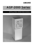
Working Screens
Working screens, as their name implies, allow you to enter, edit, and review data. Working screens
are usually divided into fields or blocks of the screen where specific information is entered. Figure
2-8 shows an example of a working screen.
Figure 2-8
Field
MAS Local 01/03/92 16:10
Alarm Dispatch
CS
01/03/92 16:10
CS-002
Name --->CS# (P) 90-1010
(S)
Installer 3000
SOUTHLAND BANK
BIGTIME BANKING CHAIN
CI
1754 EDINGER AVE
BR# 112-000
HIGH PRIORITY SERVICE
SANTA ANA BRANCH
Type
SEC. DIR. HARRY SMITH
SANTA ANA
CA 92707
Specl
OFFICE# 213-294-2845
UDF1 BANK
UDF2 ULAA
SType
R/S?
En/Xt
MapTyp
Map#
01/03/92 16:08:53
8 PERIMETER-SHOCK SENSOR
DRIVE-THRU WINDOW
Page
General Page
1 DISPATCH POLICE
2 CONTACT:
3 JIM KELLY - PRES 714-102-2928
4 FRANK BIOLA - VP 714-102-2423
--Date-- -Time Zone- Code Event Description--- Zone Comment-------- Page
1 01/03/92 16:08
8
PERIMETER-SHOCK SENS DRIVE-THRU WINDOW
2 01/03/92 16:07
PERIMETER-SHOCK SENS DRIVE-THRU WINDOW
3
4
5
Next: OPEN VERIFY/CLOSE
AS: ALARM A
Command
Line---------->CL'ist#, GO#, H'ist, M'ode, O'flo, SC'hed, Z'one, L'og, or ?
In Figure 2-8, the first field is CS#. After you enter the information into all fields, the cursor moves
to the command line. The command line is a series of options which appear at the bottom of the
screen. You'll use these options to change, save, and work with CS data.
Moving to Another Screen
A simple rule to remember when using MAS software is this: typing ; (semicolon) at the command
line or at the first position of any field, and pressing [NEW LINE] will take you back to the MAIN
MENU (Screen 0). This is a quick and easy method of returning to a known position within CS.
When you access a menu screen, the cursor appears beside the prompt, ENTER PROCEDURE NUMBER.
If you enter the number of a working screen or another menu screen, the selected screen is
Getting Started 2-10
MAS Central Station, 5.50
immediately displayed. If you enter the number of a screen that does not exist, the menu screen is
redisplayed.
From a working screen the procedure is slightly different. To access a different working or menu
screen, move the cursor to the command line and enter a semicolon (;) followed by the number of
the screen you wish to use.
You may also move to another working or menu screen from any field of a working screen. Simply
move the cursor to the beginning of any field and enter a semicolon (;) followed by the number of
the screen you wish to use. The selected screen is immediately displayed without saving the
information displayed on the previous working screen.
For example, if you type ;15 and press [NEW LINE], Screen 15 is displayed. If you select the number
of a screen that does not exist or if the field cannot accommodate the entire screen number, the
previous menu will be displayed.
Moving From Field to Field
When you access a working screen, the cursor is usually positioned in the first field where you will
enter data. If the field is blank, enter the appropriate information and press [NEW LINE] to move
the cursor to the next field.
You may move back one field by moving the cursor to the first position of a field and entering \
(backslash).
You may move the cursor to the command line by entering a period (.). From the command line,
you can move to any field in the screen to add or edit information by entering the number of the
required field you wish to edit.
MAS Central Station, 5.50
Getting Started 2-11
Entering Data
To enter data into a field on the CS system, type the characters required, then press the [NEW LINE]
key to move the cursor to the next field.
When you first access a working screen, information may already be displayed in the field. This is
called default data. Some of "defaults" have been established by MAS and may not be changed.
Other default information is controlled by the Processing Options Screen.
•
If the default information displayed for a field is correct, press [NEW LINE] to accept that
information and move the cursor to the next field.
•
If you wish to remove the default information and leave the field blank, pressing [SPACE
BAR] followed by [NEW LINE] deletes the default information and moves the cursor to the
next field.
•
If you wish to replace the default information with new data, enter the new data in that field
and press [NEW LINE].
Some fields may not be left blank. If you attempt to bypass the field, the CRT sounds a warning
beep and the cursor will not move to the next field.
Entering Dates
You may enter dates using either the North American or the European date format. The North
American date format is MMDDYY, where MM is the numerical value of the month, DD is the day,
and YY are the last two characters of the year. The European date format is DDMMYY.
To use the North American date format, set the EUROPEAN DATE FORMAT Field on Screen 101,
PROCESSING OPTIONS, to N; to use the European date format, set the field to Y.
When you enter dates, remember the following:
•
You must enter the month and day but do not have to enter the year; if you do not enter the
year, the current year will be entered automatically.
•
Include a leading zero for single-digit months and days.
•
Do not enter slashes, spaces, or other characters; slashes will be inserted automatically.
For example, assuming the current year is 1994, to enter April 3, 1994, in North American format,
type 0403. After pressing [NEW LINE] the date appears on screen as 04/03/94.
Entering Times
Times are entered using the format HHMM , where HH represents the hour and MM represents the
minutes. You do not need to enter a colon (:) between the hours and minutes; a colon will be
inserted automatically.
All times should be entered using the 24-hour clock. For example, 5:30 p.m. would be entered as
1730.
Getting Started 2-12
MAS Central Station, 5.50
Editing Data
Several screens in the Central Station system require that you enter many lines of text. To make it
easy to edit this type of information, you may use the command line option E#.
The steps for using the edit command are as follows:
1.
Access the screen where the information to be edited is located.
2.
Enter the appropriate code number or account number to access the information to be
edited.
3.
Move the cursor to the command line. Type E followed by the line number of the
information to be edited.
You may use the following conventions in moving the cursor over the text to be edited:
•
The right arrow key [→] moves the cursor one space to the right of its current position
without deleting any text.
•
The left arrow key [←] moves the cursor one space to the left of its current position without
deleting any text.
•
Hold [CTRL][A] to move the cursor to the end of the line without deleting any text.
•
Press [HOME] to move the cursor to the beginning of the line without deleting any text.
•
Hold [CTRL][E] to insert text where the cursor is currently positioned. Press [CTRL][E]
again to return to typeover mode.
Recalling an Account Number
The RECALL feature allows you to recall up to the last 10 CS accounts used on a particular screen by
entering ;R in the CS# Field. This feature can be used on the following screens:
Screen 2
Screen 4
Screen 5
Screen 7
Screen 41
Screen 42
Screen 43
Screen 44
Screen 45
Screen 46
Screen 47
Screen 48
Screen 49
MAS Central Station, 5.50
Alarm Dispatch
Schedule View
Timed Event View
Event History View
Site-Sub Account Maintenance
Dispatch Data Entry
Zone - Event Code Update
Schedule Update
CS Mail to Address
Account Passcard Maintenance
Primary Dispatch Instructions
Overflow Maintenance
Permit Update
Getting Started 2-13
Printing Reports
Many screens in CS allow you to print a paper copy of a report to your printer. When you see the
option 'GO' to Print at the command line, you have the choice of using: GO or GOX to print a paper
copy of the report, or using GOV or display the report on your screen.
'GO'
The GO command sends the report directly to the printer.
'GOV'
The GOV command displays a copy of the report on your screen instead of sending it to the printer.
This command is useful because it allows you to review data without printing a report.
When the GOV command is used, the report will scroll continuously on the screen. To stop the
scroll, hold [CTRL] S. To start the scroll again, hold [CTRL] Q.
To break out of a long report that is scrolling on your screen, hold [CTRL] C, then hold [CTRL] A.
Usually you'll need to press [NEW LINE] after breaking out of a report to display the Main Menu.
When reports are sent to the screen using the GOV command, they may not look the same as they
would on a hard copy. This is because the computer screen only displays 80 characters on each line,
while some reports can contain up to 132 characters on a line. When one of these reports is
displayed on the screen, the ends of each line will be "wrapped" underneath the preceding line.
'GOX'
The GOX command allows you to change the printer to which the report will be sent. After entering
GOX, screen NQ-002 (Figure 2-9) will appear.
Figure 2-9
Port= 12
Queue/PCS Default Entry
NQ-002
.............................Printers/Descriptions..............................
1-CITOH
2-D400/P321
3-D400/OKI
4-SP MAIN PRT
Default: 2-D400/P321
............................Printer Control Strings.............................
1-TOS/HS/17
2-TOS/HS/10
3-TOS/PRES/10 4-TOS/COUR/10
5-OKI/DP/10
6-OKI/DP/17
7-OKI/CORR/10 8-OKI/CORR/17
62-CI-NOTHING 63-TOS-NOTHING 64-PTX-NOTHING
Default: 2-TOS/HS/10
Getting Started 2-14
MAS Central Station, 5.50
P##, S##, M'ore, N'ext or 'GO'
To print a report from a different printer, enter P and one of the printer numbers shown in the upper
portion of the screen under PRINTERS/DESCRIPTIONS.
The printer control strings allow you to choose the quality and size of the characters printed on your
report. To select a printer control string, enter S and the appropriate number. The printer must be
able to print the quality and size of character you select or the message PRT. TYPES DON'T
MATCH! will be displayed.
To send the print job to the printer selected, at the command line enter a semicolon (;) or type GO.
Note: You may also access Screen NQ-002 by entering P at the
command line of the CS Main Menu (Screen 0). This allows you
to select or change your default printer without printing.
Interrupting a Print Job
There are two methods you may use to interrupt a report while it's processing but before it begins
printing:
1.
2.
You may press the [ESC] key, or,
You may hold the [CTRL] key and press [C][A].
To interrupt a report while it's printing, see your System Administration Manual.
MAS Central Station, 5.50
Getting Started 2-15
Saving Data
Entering S at the command line saves the information currently displayed in the fields but does not
clear the information from the screen; the message SAVED is briefly displayed and the CRT beeps.
When the message UNABLE TO SAVE is displayed, the cursor will move to the field which contains
invalid information. When the information in that field is corrected, the message SAVED will be
displayed and the CRT will beep. (If the SAVED message does not appear, enter S again to be sure
the information is saved).
Signing Off
Signing off from the CS software is the same for all types of computer systems. You may sign off
from the CS Exit Menu, Screen 80 or from any other menu. Whenever an operator signs off, the
accounts he was using are released and may be accessed by other operators.
Signing Off From the CS EXIT MENU
To sign off from the CS EXIT MENU, access Screen 80:
Figure 2-10
Monitoring Automation Systems
04/09/93
10:39
Central Station 5.50.00
CRT: 62
CS-080
~~~~~~~~~~~~~~~~~~~~~~~~~~~~~~~~~~~~~~~~~~~~~~~~~~~~~~~~~~~~~~~~~~~~~~~~~~~~~~~
~
CS Exit Menu
81 Inventory System
86 Sign Off
88 SOS System
Enter Procedure Number
Getting Started 2-16
MAS Central Station, 5.50
At the prompt, ENTER PROCEDURE NUMBER, type 86. The CS EXIT MENU is replaced by the sign on
screen (Figures 2-2 through 2-7) and the terminal is now ready for another user to sign on.
Signing Off From Other Screens
To sign off from any other menu, enter ;86 in the first position of any field or at the command line of
any screen.
Accessing the System for On-Line Support (SOS)
SOS allows MAS software users to communicate electronically with the MAS support staff. You can
create service tickets on your computer to request help or to report problems. These requests will be
automatically transmitted to MAS via modem. MAS's response to your request will be
automatically transmitted back to you.
You may access SOS in several ways:
•
Type SOS at the CS MAIN MENU (Screen 0).
•
Type ;88 at any CS Menu, Screen or Field.
•
Type 88 at the command line of the CS Exit Menu, (Screen 80).
For more information, refer to your SOS Instruction Manual.
Summary of Frequently Used Commands
Enter ;
Enter a semicolon to return from any screen to the previous menu.
Enter ;<screen no> Enter a semicolon and a screen number to go from any screen to the screen
specified.
Enter .
Enter a period to move the cursor to the command line at the bottom of the screen.
Enter \
Enter a back-slash to move the cursor backwards one field.
Enter N
Enter the letter N to clear the screen for the next entry.
MAS Central Station, 5.50
Getting Started 2-17
Enter M
Enter the letter M to display an additional page of information.
Enter S
Enter the letter S to save the entry.
Enter L
Enter the letter L to log the event into history.
Enter D
Enter the letter D to immediately move to Screen 2, Alarm Response/Dispatch
Enter G
Enter the letter G to immediately move to Screen 42, Dispatch Data Entry
Enter 86
Enter the number 86 to sign out of the currently used application. It only works
from menu screens.
Summary
In this section you learned how to sign on and off CS, select a menu option, enter data, move the
cursor, and use print commands. In the next section, you'll learn the basic procedures needed to set
up and use the CS system.
Getting Started 2-18
MAS Central Station, 5.50
Section 3 - Setting up Your CS System
Before You Begin
Before you begin to set up your CS system you should read the "Introduction" and "Getting Started"
sections of this manual.
What You'll be Learning
This section is of interest to CS managers who will determine the structure for CS information and
to data entry clerks who will set up the data based on the manager's specifications. In this section
you'll learn to:
•
Set up information which is common to many CS accounts, such as the companies
which install your subscribers' alarm systems and the agencies which are
dispatched to your subscribers's sites when an alarm is tripped.
•
Set up codes which allow you to group account activity, such as alarms, opening
and closing signals, and timer tests, for reports.
•
Define the reporting periods used to summarize CS account activity for selected
reports.
•
Set up event codes which represent the types of signals that can be received from
your subscribers' alarm systems and determines how the signal will be handled by
the CS system. You'll also set up event codes to represent the actions a dispatcher
may take to resolve alarms.
•
Set up CS locations and partitions which allow you to group accounts based on the
users that may access subscriber account information.
•
Set up categories which describe the situations where alarm monitoring may be
temporarily suspended for subscriber's account.
•
Review the options which control some of the default values that may be displayed
to dispatchers and data entry personnel. The processing options also control how
certain situations are processed by the CS system.
MAS Central Station, 5.50
Setting up Your CS System 3-1
Overview
The first part of this section shows you how to set up codes to represent information that many of
your subscribers share. For example, you may set up codes to represent the companies which
install your subscribers' alarm systems and the agencies which are dispatched to your subscriber
sites whenever an alarm is tripped. By using codes for common information, basic subscriber
information can be entered quickly and consistently.
Next, you'll learn how to set up event and resolution codes which are used to process and record
the signals sent to your receivers and all actions taken by CS operators.
In the last part of this section, you'll review the Processing Options Screen. This screen controls the
default data and prompts displayed on screens throughout the CS system.
These procedures are presented in the order in which they should be performed.
Setting up Codes for Commonly Shared Subscriber Information
The CS system allows you to use codes to represent information that is shared by many of your
subscribers:
•
•
•
Alarm installation companies
Police, fire, medical, and patrol agencies
Pages of instructions or information, such as how to disarm an alarm system
Setting up codes for commonly shared information provides the following benefits:
•
Detailed information is entered only once for each installer or agency.
information is entered in a single location, it's easy to set up and maintain.
Because the
•
Each installer, agency, or page of instructions is assigned a number. All of the information
for the installer, agency, or page of instructions may be linked with a subscriber's account
quickly and easily using that number.
Figure 3-1
#11-2939
Acct # 10-1234
Thompson, T.
123 Main St.
Los Angeles, CA
Code
100
200
300
Agency
LAPD
SFPD
NYPD
kson, A.
Maple Dr.
Angeles, CA
cy to Respond:
> Agency to Respond: 100 LAPD
100 LAPD
# 13-5724
Acct # 11-3638
O'Hara, J.
1947 River Dr.
New York, NY
n, Lueng
186th St, #D
York, NY
cy to Respond:
Agency to Respond: 300 NYPD
>
300 NYPD
3-2 Setting up Your CS System
MAS Central Station, 5.50
You'll use the screens listed below to set up codes for the basic information your subscribers share:
•
•
•
Screen 11
Screen 54
Screen 52
Common Overflow Maintenance
Installer File Update
Agency Update
Screen 11 Common Overflow File
This screen allows you to enter information or instructions which apply to one or more installers,
agencies, or accounts. By entering information as a page of common overflow, you'll only have to
edit the information on one screen if the information changes. Because common overflow
instructions are not immediately displayed to a CS dispatcher as he handles an alarm on Screen 2,
Alarm Dispatch, MAS recommends that you do not include primary dispatch instructions on this
screen. Instead, you may wish to include a common call list, service and maintenance information,
or answers to commonly asked questions.
Figure 3-2
Common Overflow Maintenance
1 Common#
CS-011
1000
2 Installer
(MASlink)
3
4
5
6
7
8
9
10
11
12
CALL ON ALL LOW BATTERIES
IF CUSTOMER REQUESTS SERVICE
ON THE ACCOUNT CALL:
714-234-8987
THIS WILL CONNECT YOU WITH
THE ON-CALL SERVICE TECH
#, E#, S'ave, N'ext, OR DEL'ete
In COMMON # enter a code number for the page of information. You'll use this code to link these
instructions to a subscriber's account, to agencies, or to installers. The code may contain up to 10
alphanumeric characters.
Field 2 is used only for systems with MASlink software. Refer to your MASlink Host System
Reference Manual for more information.
Lines 1 through 12 are used to record special instructions or information. Each line may include up
to 40 characters. If you wish to have the message flash whenever it is displayed, enter a ~ character
in the first position of the line. If you wish to have the message be underlined whenever it is
displayed, enter a | character in the first position of the line.
Searching for Common Overflow
After you've set up common overflow codes, you can search for codes matching a pattern using the
? command in the COMMON# Field on Screen 11. At the COMMON# Field enter ? followed by the
code you're searching for--you may enter up to 9 characters. The screen will display a list of
overflow codes beginning with the first code that matches the pattern you entered and ending with
the last code.
MAS Central Station, 5.50
Setting up Your CS System 3-3
If you would like a list of all common overflow codes, enter ? at the
[Enter]. All common overflow codes will be listed.
COMMON#
Field and press
A sample list is displayed in Figure 3-3.
Figure 3-3
Common Overflow Maintenance
1
2
3
4
5
6
7
8
9
10
11
12
13
14
15
16
17
18
100
1000
2000
3000
BURG
FIRE
MED
CS-011
SPECIAL INSTRUCTIONS FOR INSTALLER #100
DISPATCH INSTRUCTIONS FOR INSTALLER 1000
COMMON OFLO FOR INSTALLER 2000
COMMON OFLO FOR INSTALLER 3000
COMMON OFLO FOR BURGLARY DISPATCH
COMMON OFLO FOR FIRE DISPATCH
COMMON OFLO FOR MEDICAL EMERGENCIES
#, N'EXT OR M'ORE
Select a common overflo page to view.
Editing Common Overflow
A page of overflow information may contain many lines of text. To make it easy to edit this type of
information, you may use the edit command, E#. See "Getting Started" for more information about
the Edit command.
Deleting Common Overflow
To delete a page of common overflow, display the page to be delete on Screen 11. Move the cursor
to the command line, type DEL, and press [NEW LINE]. The selected page will be deleted.
3-4 Setting up Your CS System
MAS Central Station, 5.50
Listing Common Overflow Pages
A printout of all common overflow information may be printed from Screen 27 Common Overflow
Printout. Refer to "Reporting" for further information.
Assigning Common Overflow to an Installer, Agency, or Account
A single page of common overflow information may be assigned to each agency and installer. You
may assign to an account as many pages of common overflow as necessary.
Common overflow is assigned to an installer on Screen 54, Installer Update. The common overflow
may be displayed by a CS operator on Screen 2, Alarm Dispatch, as he dispatches alarms for
accounts which have been linked with the installer. This procedure is described in the next section,
"Installer Update"
Common overflow is assigned to an agency on Screen 52, Agency Update. The common overflow
may be displayed by a CS operator on Screen 2, Alarm Dispatch, as he dispatches alarms for
accounts which have been linked with the agency. This procedure is described in "Agency Update"
later in this section.
Common overflow is assigned to a subscriber's account on Screen 42, Dispatch Data Entry. The
common overflow may be displayed by a CS operator on Screen 2, Alarm Dispatch, as he
dispatches alarms for the account. This procedure is described in the next chapter "Setting up
Subscriber Accounts."
MAS Central Station, 5.50
Setting up Your CS System 3-5
Screen 54 Installer Update
The Installer File Update Screen allows you to group your subscribers' accounts into different
categories for reporting purposes. The installer number is a major sorting category for virtually all
reports and is second in importance only to a subscriber's account number. An installer is assigned
when you set up a subscriber's account on Screen 42 Dispatch Data Entry.
Installer numbers may contain up to six numeric characters. How you use installer numbers for
grouping your subscriber accounts depends on what type(s) of service you offer: alarm installation,
monitoring, or both. Here are some account types you might have:
Dealers (Installers)
Commercial
UL Burglar
Residential
Supervised
UL Fire
Contract Central Stations
If your central station monitors the subscriber accounts for several alarm installation companies,
you can assign a unique installer number to each company. This will allow you to print detailed
and summary reports for each installer's accounts.
Example:
Installer Number
100
110
120
Dealer
ABC Alarm Company
Creative Security Inc.
Stadium Alarm Company
Leaving open numbers between each dealer allows for grouping account types by dealer, if desired.
Example:
Installer Number
Dealer/Account Type
100
101
102
ABC Alarm Company
ABC Alarm Co. (Supervised)
ABC Alarm Co. (U.L. Fire)
120
121
122
Stadium Alarm Company
Stadium Alarm Co. (Supervised)
Stadium Alarm Co. (U.L. Fire)
3-6 Setting up Your CS System
MAS Central Station, 5.50
Full Service Alarm Companies
If you install and monitor your subscribers' accounts exclusively, then you would benefit by
grouping your accounts by the type of service you provide. This way you can print detailed and
summary reports for each account type.
Example:
Installer Number
Dealer
010
015
020
025
Commercial (Non-Supervised)
Commercial (Supervised)
Residential
U.L. Fire
Full Service Alarm Company Plus Contract Central Station
If you install and monitor your own subscribers' accounts as well as monitor those of other alarm
installation companies, then you can reserve a range of installer numbers for in-house accounts and
a range for installer accounts.
Example:
Installer Number
Dealer
100
200
300
400
In-House Accounts
ABC Alarm Company
Creative Security Inc.
Stadium Alarm Company
The flexibility of grouping your accounts is not limited to the examples above. For example, you
may choose to group your accounts by city, county, state, or some other area you define.
Whichever way you choose to group your accounts, be sure to define some rules for consistency
before you create installer numbers.
Figure 3-4
Installer File Update
1 Inst #
CS-054
1000
2 Message
3 Message
4 Message
5 Message
RESIDENTIAL HIGH SECURITY
MUST RESPOND WITH DOGS
SERVICE AREA 7
ON CALL PAGER 213-354-9023
CFR Information
6 Name
7 Address
8 Address
9 CSZP
MAS Central Station, 5.50
Setting up Your CS System 3-7
12 Phone
13 Return to Installer
14 Default Empl #
15 Common#
(Y=Installer prints on bottom of CFR)
#, S'AVE, N'EXT OR D'ELETE
Enter an Installer Code
In INST #, enter up to six numeric characters to represent the installer. MAS suggests that you begin
numbering installers at a number other than 1 and that you number them by tens (10, 20, 30, etc.) or
hundreds (100, 200, 300, etc.) rather than by ones (1, 2, 3, etc.). This way, you can easily add
installers later on.
Enter Important Installer Information
In Fields 2 through 5, you can create up to four lines of text including any useful information about
the installer. Enter up to 25 alphanumeric characters per line. When a dispatcher displays a
subscriber's account information on the Alarm Dispatch screen, the information for the installer
assigned to that account will also be displayed.
•
For alarm installation companies you may use these lines for the companies' names and
phone numbers.
•
Because a subscriber's installer information is automatically displayed on the Alarm
Dispatch Screen, you may use these lines for standard dispatch instructions.
You may have the message flash whenever it is displayed by entering a ~ character in the first
position of the line. If you wish to have the message be underlined whenever it is displayed, enter a
| character in the first position of the line.
Installer Information for the Customer File Report
Whenever a subscriber's account is added or edited, a Customer File Report may be printed from
Screen 281 and mailed to the subscriber to verify that the information has been entered correctly.
The installer information entered in Fields 6 through 12 on Screen 54 will be printed on the
Customer File Report.
In NAME, enter the name of the installation company. You may use up to 30 alphanumeric
characters. Enter the installer's address in Fields 7 and 8. CSZP represents three fields where you
can enter the installer's city, state, and zip code. After entering each piece of information, press
[NEW LINE] to move to the next field. In PHONE, enter the installer's telephone number, including
the area code--even for local telephone numbers.
In RETURN TO INSTALLER, enter Y if the installer's address should be printed at the bottom of the
Customer File Report Enter N if the installer's address should not be printed at the bottom of the
Customer File Report.
3-8 Setting up Your CS System
MAS Central Station, 5.50
Designate a Service Technician
DEFAULT SERVICE EMPL #
•
•
•
•
is used only if:
Your central station uses the MAS Service System.
You've set up employees in the MAS Service System.
You have not set up accounts in the MAS Service System.
There is a particular service technician that will be responsible for servicing the
accounts for this installer.
If all of these conditions apply, enter the employee number of the service technician that normally
services the accounts for this installer. (Service technicians are assigned an employee number on
Screen 566 Employee Update.) If there is no single employee that would normally service all of the
accounts for this installer, leave this field blank.
If you enter an employee number, the service employee will automatically be assigned to the
installer's accounts when they are transferred to the Service System.
Common Overflow
Recall that you may create pages of instructions or information on Screen 11, Common Overflow
Maintenance. You may assign a page of common overflow information to the installer by entering
a common overflow code in the COMMON # Field. The CS dispatcher may display the common
overflow page as he handles an alarm for one of the installer's accounts on Screen 2 Alarm
Dispatch.
Printing a List of Installers
A listing of the installers you set up on Screen 54 can be displayed or printed from Screen 74
Installer File Printout. Refer to Reporting and Sample Reports for further information.
MAS Central Station, 5.50
Setting up Your CS System 3-9
Screen 52 Agency Update
The Agency Update Screen allows you to set up information for each agency that services your
subscribers. Agencies include police, fire departments, patrol service companies, and medical
agencies.
Begin by preparing a list of the names and phone numbers of all agencies that service your
subscribers.
Next, assign each agency on the list a number. You may use any number between 1 and 65,535.
Two agencies can be assigned the same number as long as they are different agency types (e.g.
police and fire department). MAS suggests that you begin numbering the agencies at a number
other than 1 and that you number them by tens (10, 20, 30, etc.) or hundreds (100, 200, 300, etc.)
rather than by ones (1, 2, 3, etc.). This will allow you to easily add agencies later, if necessary. You
also should group agencies geographically according to city, county, or state.
Figure 3-5
Agency Update
1
2
3
4
5
6
7
8
9
12
13
15
17
18
19
20
21
CS-052
Agency Type
POLICE
Agency Code
100
Name
LAPD
Phone 1
213 555-1212
Phone 2
213 872-7123
Mailing Name
LOS ANGELES POLICE DEPARTMENT
Address 1
Address 2
City St Zip
LOS ANGELES
CA 92621
Port Number
41
Active (Y/N)
Y 14 Modem Phone 1 7862
Active (Y/N)
N 16 Modem Phone 2
Permit Required
B (D'ispatch, E'ntry, B'oth or N'either)
Permit Type
1 SLIDING 4/5
Permit Group
(0 - ITSELF)
Permit Comment
Common#
#, S'ave, or N'ext
3-10 Setting up Your CS System
MAS Central Station, 5.50
Indicate the Agency Type and Agency Code
In AGENCY TYPE, you may enter one of the following letters to indicate the type of agency:
P - Police Department
M - Medical
MAS Central Station, 5.50
F - Fire Department
T - Patrol
Setting up Your CS System 3-11
In AGENCY CODE, enter the code you want to assign to a agency. The agency code may be any
number between 0 through 65,535. If you wish to see a list of agencies which have already been set
up, enter a comma (,) in the AGENCY CODE Field. The Agency Lookup Window, shown below, will
be displayed:
Figure 3-6
17
18
19
20
21
22
17
18
19
20
21
22
23
Police Agency Lookup Window
Sort (A'gency Code, N'ame, C'ity/St, P'hone) N
#
1
2
3
4
5
6
7
8
.Code Name................
2000 DENVER POLICE DEPT.
City...........
DENVER
St
CO
Start DENVER
Phone 1.....
555-555-0239
Phone 2...
555-555-2389
#, N'ext, M'ore, P'revious, P'hone#.#, or Q'uit
In SORT, enter A to list agency information in order according to agency code; N to list
information by agency name; C to list information by city; or P to list information by phone
number.
The value you enter in START depends on the sort selection you chose. For example, if you
chose to list agency information by name and you'd like to find the agency code for the
Denver Police Department, enter DENVER in START.
You may use the P'hone#.# command to use the Autodialer to dial the selected telephone
number. For more information about Autodialing, refer to "Basic Monitoring."
Enter the Agency Name, Address, and Phone Numbers
In NAME, enter the name of that agency, such as DENVER POLICE DEPT. In PHONE 1 and PHONE 2,
enter telephone numbers for that agency.
You may enter a mailing name for the agency in Field 6. This name may be used to override the
agency name when tickets are printed. Enter a mailing address for the agency in Fields 7 through 9.
Can the Agency Receive Dispatch Info via Modem?
Certain agencies may be capable of receiving dispatch tickets via a modem or direct line. If so, you
can enter information about their modem in the lower portion of Screen 52.
If the agency can receive dispatch tickets via a modem, enter the port from which tickets are
dispatched in PORT NUMBER. In Fields 13 and 15, indicate whether or not the receiving modem is
active (ready to receive information) or inactive (not ready to receive information). In Fields 14 and
16, enter the telephone number of the receiving modem.
3-12 Setting up Your CS System
MAS Central Station, 5.50
Are Permits Required for Agency Response?
Fields 17 through 20 are used with the permit feature. Refer to "Special Monitoring Features" for
further information.
Common Overflow
Recall that you may create pages of instructions or information on Screen 11, Common Overflow
Maintenance. You may assign a page of common overflow information to the agency by entering a
common overflow code in the COMMON # Field. The CS dispatcher may display the common
overflow page as he handles an alarm on the Alarm Dispatch Screen for an account to which the
agency has been assigned.
Recall that Common Overflow pages are set up on Screen 11, Common Overflow Maintenance.
Printing a List of Agencies
A report of the information shown on Screen 52 can be printed from or displayed on Screen 72
Agency Printout. Refer to "Reporting" and "Sample Reports" for further information.
MAS Central Station, 5.50
Setting up Your CS System 3-13
Grouping Activity for Summary Reporting
Screen 102, Reporting Control File
Screen 102 Reporting Control File allows you to group, for reporting purposes, the types of events
that your CS system and operators handle. You can categorize events into up to 36 different
reporting groups.
The categories you define on this screen are used as the reporting codes on the Event Code Update
(Screen 51 Event Code Update). These categories will also become the report columns on the
following summary reports:
•
•
•
•
•
Screen 118
Screen 204
Screen 205
Screen 210
Screen 211
Monthly Summary View
Excessive Activity Report
Combined Activity Report
Summary Activity Report
Shift Activity Report
Some examples of categories you might use are shown below:
Figure 3-7
Reporting Code Description File
1-0 ALARMS
2-1 RESTORES
3-2 LOW BATTRY
4-3 TROUBLES
5-4 OP/CL
6-5 AUTO ABORT
7-6 VRT SIGNLS
8-7 TIMER TEST
9-8 TEST SIGNL
10-9 UNKNWN ACC
11-A
12-B MED DISP
13-C GUARD DISP
14-D PD DISP
15-E FIRE DISP
16-F FALSE SUB
17-G FLSE EQUIP
18-H FALSE UNK
CS-0102
19-I IRREG O/C
20-J SVC REQST
21-K ON/OFF TST
22-L DATA CHNG
23-M CALL SUB
24-N CALL RP'S
25-O CALL ALMCO
26-P OUT OF SVC
27-Q IN SVC
28-R
29-S SUB ERROR
30-T SUB ABORT
31-U
32-V
33-W
34-X
35-Y PARTIAL CL
36-Z FULL CLEAR
#, S'ave
3-14 Setting up Your CS System
MAS Central Station, 5.50
Defining Monthly Reporting Periods
Screen 103, Reporting Periods
Screen 103 Reporting Periods is used to define the periods for which account activity (alarms,
opens, closes, timer tests, etc.) is accumulated on the following summary reports:
•
•
•
•
•
Screen 118
Screen 204
Screen 205
Screen 210
Screen 211
Monthly Summary View
Excessive Activity Report
Combined Activity Report
Summary Activity Report
Shift Activity Report
Figure 3-8
Reporting Periods
CS-0103
Start
End
1
2
3
4
5
6
7
8
9
10
11
12
13 12/01/92 12/31/92 Current
14 01/01/93 01/31/93 Next
#, S'ave
When you first set up your CS system, you need only fill-in dates in the CURRENT and NEXT Fields.
To complete the dates for the current month (reporting period), move the cursor to Field 13. Enter
the date of the first day of the month in the START column of CURRENT; press [ENTER]. Next, enter
the date of the last day of the month in the END column of CURRENT; press [ENTER].
In Field 14, enter the first and last dates of the following month. Once the CURRENT and NEXT date
ranges have been entered, this screen should never be modified again. Instead, the dates may be
advanced using Screen 117 Event History Rolling. Refer to "Maintaining the CS System" for further
information.
MAS Central Station, 5.50
Setting up Your CS System 3-15
Setting up Event Codes
Screen 51, Event Code Update
Event codes describe the signals that may be received from your subscriber sites and the actions a
CS dispatcher may take in resolving these events. An event code is assigned to an incoming signal
and determines how that signal is processed by the CS system and by CS operators. Resolution
codes are those which describe an operator's actions in resolving an alarm. Generally, however, the
terms "event" and "resolution" code are used interchangeably.
There are three possible paths an event can travel within the CS system. The path that the event
travels depends on the response code assigned to the event. A response code may define an event as
one of the following:
•
An alarm which requires an operator to resolve and clear the alarm .
•
An event which is automatically recorded to subscriber account history without ever being
seen by a CS dispatcher (log always).
•
A conditional event which checks the opening and closing times scheduled for a
subscriber's account and/or which verifies an identification code for the subscriber' account
to determine the action to be taken.
Some event and resolution codes have already been defined for you by MAS. These codes are listed
in Appendix D. If you wish, additional event or resolution codes may be defined by you on Screen
51.
Figure 3-9
MAS
1
2
3
4
5
6
7
Event Code
Description
Reporting Code
Response Code
Resp. Priority
Event Class
Wait
8 Wait Event Code
9 Status Change
10
11
12
13
14
15
16
17
Dispatch Code
Alternate Desc
Can RPC'S Use?
False Dispatch
Late Event Code
A'bort OK, A'B'ort
VRT Type (1-99)
Equivalent Code
Event Code Update
4610
PARTIAL CLEAR
O OPEN/CLOSE
0 OPERATOR ALWAYS
0
O
0 1=Set,2=Clr,3=Eqres
4=Disarm,5=Arm
0
A O=Opn,C=Cls,A=Alrm,R=Rst
T=Trbl,N=Norm,X=Outage
N
N
0
(NOT USED)
(Y/N) MASlink Only
(Y/N)
CS-051
18
19
20
21
22
23
24
25
26
27
28
29
30
Min User Level
Disposition Type
Disposition Code
Prompts (P/C/B/N)
Confirm Required?
ClrTest (R/N)
Agency Type (PFMT)
Dual Custody (Y/N)
Screen 12 to S'kip
Ticket Type
Global ZD Page
Event Type
Zone Group
4
1
PC
P
N
N
0
0
#, S'ave, or N'ext
3-16 Setting up Your CS System
MAS Central Station, 5.50
Assign a Code
In EVENT CODE, assign a code to represent an event or operator action. An event code may contain
up to four numeric characters.
Describe the Code
In DESCRIPTION enter up to 20 characters to describe the event or operator action. Be as descriptive
as possible when describing an event code. For operator actions, the event's description will appear
on Screen 2, Alarm Dispatch, as the operator handles an alarm. An event's description will also
appear in a subscriber's account history and most history reports. Following are two examples of
how a description can be used to inform and guide an operator:
•
Event Code Description: FIRE-SMOKE-CALL PREM
FIRE indicates the type of alarm. SMOKE tells the operator the type of device activated, in
this case a smoke detector. CALL PREM gives the operator initial instructions for handling
the alarm, in this example to call the premises.
•
Event Code Description: FIRE-PULL-DISP FD
FIRE indicates the type of alarm. PULL tells the operator the type of device activated (i.e. a
fire alarm device has been pulled). DISP FD gives the operator initial instructions for
handling the alarm.
Using event codes to provide information to the operator and guide his initial actions ensures
consistency and uniformity in recording the steps taken to resolve an event.
Assign a Reporting Code
The REPORTING CODE determines the category an event will be grouped with on the following
summary reports:
•
•
•
•
•
Screen 118
Screen 204
Screen 205
Screen 210
Screen 211
Monthly Summary View
Excessive Activity Report
Combined Activity Report
Summary Activity Report
Shift Activity Report
When event history is posted, the unposted events for each account are checked to see which
reporting code was assigned to that event at the time it was logged. Then, as the events are posted,
the appropriate reporting category is increased by one for the summary reports.
Reporting codes are set up on Screen 102, Reporting Code Description File.
3-18 Setting up Your CS System
MAS Central Station, 5.50
Assign a Response Code
The RESPONSE CODE determines how a signal will be processed by the CS system. The possible
response codes are as follows:
0 - Operator Always. An event with this assignment will always be sent to and displayed
on the Alarm Status Monitor (Screen 14) so an operator may take action to resolve the
signal.
1 - Attempt to Log. An event with this assignment will always be checked against an
account's schedule (Permanent Schedule Maintenance, Screen 44) or other expected events
(e.g. timer tests, etc.). If the event occurred outside of the schedule, an alarm may be
generated.
2 - Always Log Only. An event with this response code will never be seen by a CS operator.
Instead it will be recorded (logged) directly to the account's history (Event History Display,
Screen 7).
3 - Verify Passcard/Verify Schedule. When this assignment is used, the event must be
within a scheduled time and the customer who initiated the event must have the
appropriate user i.d. (Customer passcards are defined on Screen 46 Account Passcard
Maintenance.) If the event occurs outside of the schedule, an alarm may be generated. If
the user does not have the appropriate user ID, an alarm will be generated.
4 - Passcard Lookup/Log Only. When this response code is used, the event may occur at
any time but the customer's user i.d. will be recorded with the event type to the customer's
history. If a name is assigned to the event's passcard, that name will appear on reports and
history screens.
5 - Passcard Lookup/Verify Schedule. When this assignment is used, the event must be
within a scheduled time and the customer's user i.d. will be recorded with the event type to
the customer's history. If a name is assigned to the event's passcard, that name will be
posted with the event to the customer's history. If no name is assigned to the event's
passcard, the passcard number and event will be posted to the customer's history. If the
event occurs outside of the schedule, an alarm may be generated.
6 - Verify Passcard/No Schedule. When this response code is used, the event may occur at
any time but the customer who initiated the event must have the appropriate user i.d. If the
user does not have the appropriate ID, an alarm will be generated.
7 - Operator Always/Passcard Lookup. Events assigned this response code will always be
processed as alarms and, in addition, will verify the customer's i.d. sent with the signal. If a
name is assigned to the customer's passcard, that name will be posted with the event to the
customer's history. If no name is assigned to the event's passcard, the passcard number and
event will be posted to the customer's history.
Response codes 3, 4, 5, 6, and 7 are used for event codes associated with the Schedule and Passcard
features. Refer to "Special Monitoring Features" for more information.
MAS Central Station, 5.50
Setting up Your CS System 3-19
Establish a Priority for Alarms and Events
In order to prioritize alarm signals which require operator action, a PRIORITY number between 1 and
255 is assigned to each event/resolution code. MAS recommends that you group the priority
assigned to similar signals; for example, you might use priorities 10 through 19 for fire alarms, 20
through 29 for burglaries, and so forth. This would allow you to assign a higher priority to
burglaries occurring in a jewelry store than you would to a warehouse.
Classify Events
In EVENT CLASS, you can use a single, alphabetic character except S or T, to classify the event code.
The EVENT CLASS you assign to an event is important because events may be purged (deleted) from
your CS system by event class and because you may print Supervised Mail Out Reports from Screen
24 by event class.
Event classes S and T are reserved by MAS to be used as follows:
S - Events which occur while an account is out-of Service.
T - Events which occur while an account or zone is on test.
Define a Wait Period for Non-Digital Transmitters
defines special processing required for non-digital panels. On non-digital panels, you may
receive a series of alarms prior to an open or close signal. If an account is within its open or close
times, the system will hold these alarms for a specified amount of time, while waiting for the open
or close condition. If the open or close is received within the allowed time frame, the alarm signals
will be logged to history and the open or close signal will be processed normally. If the open or
close is not received within the specified time, the signals being held will be processed as alarms.
There are five possible entries for this field:
WAIT
1 - Set. If a signal with this code is received during a scheduled open or closing time, this
signal is placed in the wait file for the amount of time specified in the EN/XT Field
(entry/exit delay) on Screen 42.
2 - Clear. If a signal with this code is received, all signals previously received and placed in
the wait file are cleared (deleted without being processed further).
3 - Eqres. This code is assigned to open or close signals so they will not be placed in the
wait file and will always be processed as a normal open or close.
4 - Disarm, wait entire entry delay. There are times when another signal which is part of
the opening sequence is received after the open signal is received. If these subsequent
signals have been assigned a wait code of 4 and are received within the entry delay time
(from Screen 42), they will not be processed as alarms but will be recorded (logged) to the
customer's history.
5 - Arm, wait entire exit time. There are times when another signal which is part of the
3-20 Setting up Your CS System
MAS Central Station, 5.50
closing sequence is received after the close signal is received. If these subsequent signals
have been assigned a wait code of 5 and are received within the exit delay time (from Screen
42), they will not be processed as alarms but will be recorded (logged) to the customer's
history.
is to be completed only for event/resolution codes which are assigned a wait code
of 3. In this case, you must enter the event/resolution code which has the processing characteristics
that this new code should have.
WAIT EVENT CODE
Should the Code Change the Account's Alarm Status?
When an event is received for an account, you may want the event to change the account's status.
For example, you may want opening events to change an account's status to "opened." When a CS
operator views account information on the Alarm Dispatch Screen, the account's current status is
displayed in the AS Field.
If you want an account's status to change whenever this event code is received for the account,
enter the status to which the account is to be changed in STATUS CHANGE. Choose from the
following statuses:
O
A
T
X
Opened
Alarm
Trouble
Outage
C
R
N
Closed
Reset
Normal
If you do not want this resolution code to change the status displayed on the Alarm Dispatch
Screen, do not enter a value in this field.
Assign a Dispatch Code
A DISPATCH CODE can be assigned to an event code so you can search for that particular code in a
subscriber's account history (Screen 7 Event History View). The dispatch code may be a single,
alphanumeric character. Following are examples of how you might use dispatch codes:
A
C
E
O
R
T
Alarms
Closes
Environmental
Opens
Restores
Timer Tests
Do You Want to Display the Event Code Description in French?
You must call MAS to activate ALTERNATE DESC for you. This field displays the event code's
description in French. In addition, the event code description on Screen 2 Alarm Dispatch will be
displayed in French; however the description in the subscriber's account history (Screen 7 Event
History View) will be shown in English.
MAS Central Station, 5.50
Setting up Your CS System 3-21
Can the Event Code be Used by MASlink RPC's?
CAN RPC'S USE? is used only if you have MASlink software. If this field is set to Y, alarm installers
having a remote PC, can use this event code to set up zone information for subscriber accounts on
Screen 43 ZONE - EVENT CODE UPDATE and transmit that information to your Central Station.
Can the Event Code be Logged as a False Alarm?
The FALSE DISPATCH Field is used with the Permit feature to track false alarms for your subscriber
accounts. For an event code which is logged by an operator whenever an alarm is determined to be
a false alarm, enter Y in the FALSE DISPATCH Field. For example, if you have an event code described
as FALSE ALARM, you would enter Y in the FALSE DISPATCH Field. Every time the event code is
logged to a subscriber's account, his FALSE DISPATCH counter will be increased by 1. By tracking the
number of false dispatches, you can notify a subscriber when the number of false alarms allowed
for his account is reached or exceeded. See "Special Monitoring Features" for more information
about the Permits and False Alarm Tracking feature.
Should Another Event Code be Used for Late Event Processing?
The LATE EVENT CODE Field is used with the Late Event Processing feature. If the event designated
by the event code does not occur (is late), the event designated by the late rescode will be generated.
Can the Alarm be Aborted Before Generating an Alarm?
Certain alarms that have been received by your CS system, but not yet accessed by operators, may
be aborted by the subscriber, automatically clearing his account from alarm status. To use this
feature, the subscriber's alarm panel must be able to send in a unique zone which represents the
user abort of a previously tripped alarm zone. If an operator action has been logged to the
subscriber's account after the alarm is received, the alarm may not be aborted by the subscriber.
(An operator action is an event code between 4000 and 4999.)
If you wish to use this feature:
·
Contact MAS to verify that your receiver output program can use this feature. Your
particular receiver output program may need to have this feature added.
·
On Screen 51, Event Code Update, set up the event code that will be used to abort
alarms. For the abort event code, enter B in the A'BORT OK, A'B'ORT Field.
·
On Screen 51, indicate events that may be aborted from alarm status by entering an
A in the A'BORT OK, A'B'ORT Field for those events on Screen 51.
·
Set up or add the abortable event codes as zones for the subscriber's account on
Screen 43, Zone-Event Code Setup.
·
The abort event code may be set up for the subscriber on Screen 43, Zone-Event
Code Update, or it may be processed using the receiver's default event code
processing.
3-22 Setting up Your CS System
MAS Central Station, 5.50
·
Verify that event code 3925, Alarm Abort, has been created on Screen 51 and
assigned to a response code of 2. This event code will be automatically logged as an
informational message whenever an alarm is aborted by way of this feature.
If multiple zones are tripped and the user attempts to abort the alarm, the alarm may only be
aborted if all zones are designated as abortable; otherwise, the abort event code will be logged, but
the account will remain in alarm status.
Field 16 is used with the VRT II. Refer to your VRT II Reference Manual for more information.
Should the Event be Processed Identically to Another?
Using the EQUIVALENT CODE Field, you may set up an active, operator event code and tell the CS
system that the new event code is to act the same as one of your current active, operator event
codes. An example of how you might use this feature is in setting up several event codes with
different descriptions to track "full clears."
For example, you might set up the event code "FULL CLR-OWNER ERROR." So that this event
code would be processed as a full clear, enter 4612 (full clear) in the EQUIVALENT CODE Field on
Screen 51 for the "FULL CLR-OWNER ERROR" event code.
Should Certain Users be Restricted From Logging This Code?
The MINIMUM USER LEVEL (0 - 4 allowed) assigned to an event code controls the minimum security
level a user must have been assigned for the Alarm Dispatch Screen before he will be allowed to log
the event code on the Alarm Dispatch Screen. The user's security level (0 - 7) for Screen 2 is
designated on Screen 360, Program/User Security Entry/Maintenance.
For example, if a user has been assigned a security level of 3 for Screen 2 and attempts to log an
event code having a minimum user level of 2, the user will not be allowed to log the event code.
The next four fields allow you to group event codes for easier logging of alarm and call resolutions.
Logging Event Codes Using Alarm or Call Dispositions
Disposition codes may be used for event codes which describe operator actions taken in contacting
the individuals and agencies on a subscriber's call list and in resolving an alarm. Call dispositions
describe the results of calls made to notify the subscriber (or some other individual or agency) of an
alarm. For example, you might create call dispositions to record the following information:
Line Busy
Answering Machine
Dispatched PD
MAS Central Station, 5.50
No Answer
Contacted Premise
Setting up Your CS System 3-23
Alarm dispositions may be used for event codes which describe operator actions taken to resolve an
alarm. For example, you might create call dispositions to record the following information:
False Alarm
Confirmed Crime
DISPOSITION TYPE is a one character alphanumeric code used to classify event codes into functional
groups. Currently, two codes are reserved: A for alarm dispositions and C for call dispositions.
DISPOSITION CODE
disposition type.
is a three character alphanumeric code used to identify an event code within its
Define the Cursor Movement for the Operator Action Window
In PROMPTS, enter P if a passcard is usually entered for this event when it is logged to a subscriber's
account from Screen 2 Alarm Dispatch. Enter C if a comment should be entered for this event.
Enter B if both a passcard and comment are usually entered for this event. These options only
prompt the user for an entry. It does not force the user to make an entry.
Enter N if neither a passcard nor comment are usually entered for this event.
In CONFIRM REQUIRED, enter Y if the user must enter a confirmation when this event code is logged
to a subscriber's account on Screen 2 Alarm Dispatch. Enter N if the user does not have to enter a
confirmation when this event code is logged to a subscriber's account.
Will the Event Code be Assigned to a Zone Which Requires Testing?
The CLR TEST field is for VRT II users only.
The CLR TEST feature allows you to create groups of event codes that will be assigned to zones on
Screen 43 Zone - Event Code Update. If you enter R in the CLR TEST Field, any zone which is
assigned this event code must be tested whenever the zone or account is placed on test. (If the zone
was placed on test but not tested and you attempt to clear the test using the VRT II, you will not be
allowed to clear the test.) If you enter N in the CLR TEST Field, any zone which is assigned this event
code is never to be tested whenever the zone or account is placed on test. (If the zone was placed
on test but not tested and you attempt to clear the test using the VRT II, you will not be allowed to
clear the test.)
What Agency Information Should Be Displayed When Dispatching?
The AGENCY TYPE Field is used together with the Call List feature. A call list is made up of the
individuals and agencies that should be contacted when an alarm is tripped. Different call lists
may be designated for the various types of alarms that may occur at a subscriber's site. For
example, you may set up different call lists for fire alarms, burglar alarms, and panics.
When you set up call lists for a subscriber's account, you may specify the agency to be included on
the call list or the agency to be included on a call list may be determined by the alarm that was
received.
3-24 Setting up Your CS System
MAS Central Station, 5.50
If you want the agency to be included on a call list to be determined by the alarm that was received,
enter the type of agency that would most likely need to be contacted for the alarm represented by
this event code in the AGENCY TYPE field. Choose from the following agency types:
P
F
Police
Fire Department
M
T
Medical Agency
Patrol
When call lists are built for subscriber accounts, the phone number of the appropriate agency will
be automatically referenced based upon the event code's agency type.
Note: For more information about call lists, refer to "Setting up CS
Accounts" and "Basic Monitoring."
The DUAL CUSTODY Field is not used.
If the Event is Late, Should it Appear on Screen 12, Late Event View?
For each subscriber site, you may define the normal times the site is expected to open and close by
setting up a schedule (on Screen 44, Schedule Update). The schedule includes the event code that
will be received from the site when it is opened and the event code that will be received from the
site when it is closed. If an opening or closing is late to occur, it may appear on Screen 12, Late
Event View.
Some alarm systems periodically send a test signal to indicate that the system is functioning
correctly. For each subscriber site, you may define the time that a timer test signal is expected to be
received. If the timer test is late to occur, it may appear on Screen 12, Late Event View.
If you do not wish to have events designated by this event code and which are late to occur to
appear on Screen 12, Late Event View, enter S in the SCREEN 12 TO SKIP Field. For example, you may
wish to prevent late timer tests from appearing on Screen 12. MAS recommends that you do not
use this feature for other types of late events (opens, closes, follow-ups).
Note: For more information about late events and schedules, refer to
"Special Monitoring Features."
MAS Central Station, 5.50
Setting up Your CS System 3-25
Automatically Creating a Service Ticket
The TICKET TYPE Field may be used only if your system uses the MAS Service System.
If you enter a TICKET TYPE on Screen 51, whenever the event code is logged a service ticket may be
created automatically. The information set up for the service ticket depends on the ticket type.
Ticket types are created in the Service System on Screen 594, Ticket Type Update.
Assigning Global Dispatch Instruction to a Default Zone
For each subscriber account, you'll set up a list of zones which define the types of events that may
be received from an account. For example, zones may include opens, closes, burglary alarms, fire
alarms, and device restorals. For each zone you may set up instructions to describe what an
operator should do when the zone is tripped (an alarm is generated). If the same instructions apply
to more than one subscriber's account, you may set up global dispatch instructions. Global dispatch
instructions may be assigned to more than one subscriber's account.
If an alarm is generated for a zone and it does not match the zones defined for the account on
Screen 43, Zone - Event Code Update, the alarm may be processed using a "default" event code.
(Default event codes are defined by your receiver's output program.) In such a case, the GLOBAL ZD
PAGE determines the dispatch instructions that will be displayed to a dispatcher on the Alarm
Dispatch Screen:
•
If global dispatch instructions have been assigned to the default event code, the global
dispatch instructions will be displayed with the alarm on the Alarm Dispatch Screen.
To assign global dispatch instructions to an event, enter the appropriate global dispatch
instruction page in the GLOBAL ZD PAGE Field.
•
If the dispatch instructions for your subscriber accounts are organized so that the same page
number represents the same information for each account, you may wish to display a
particular page of information when the event is received.
To display a particular dispatch page whenever the event is received, enter *NNN in the
Field, where NNN represents the number of the dispatch page to be
displayed when the given event code is in alarm.
GLOBAL ZD PAGE
For example, if dispatch instructions for fire alarms are always set up as Dispatch Page 10
for you subscriber accounts, you may wish to enter *10 for all events which represent fire
alarms.
Grouping Events for Reporting
The EVENT TYPE Field allows you to group events for reporting on the Summary Incident File
printed from Screen 296.
MAS Central Station, 5.50
Setting up Your CS System 3-27
Grouping Zones to be Placed on Test
For each subscriber account, you'll set up a list of zones which define the types of events that may
be received from an account. Zones may include opens, closes, devices to detect intrusion or
environmental changes, and device restorals.
When a device is installed or added at a subscriber's site, the service technician may trip the zone to
ensure that the signal can be received properly at the central station. To ensure that a dispatcher
will not actually dispatch on the test signal generated by the service technician, the account may be
placed on alarm. When a zone is on test, the signals generated by that zone will not appear on the
Alarm Status Monitor (Screen 14); however, its signals will be logged to the subscriber's history.
The ZONE GROUP feature allows you to create groups of zones which are to be simultaneously
placed on test. This allows a dispatcher to place a group of zones on test, rather than placing all
zones or individual zones on test.
Deleting Event Codes
Event codes may be changed or deleted using Screen 142, Resolution Code Update. Refer to
"Maintaining the CS System" for more information about Screen 142.
Assign Event Codes to Function Keys (Optional)
You may assign the most frequently-used event codes to the function keys. By assigning event
codes to the function keys, CS operators can log an event code simply by pressing the appropriate
function key. This option is described more fully in "Using Event Codes and Function Keys."
3-28 Setting up Your CS System
MAS Central Station, 5.50
Setting up Locations and Partitions
Locations are used to group related customer accounts. The groupings you create depend on the
functions and features you'll be using in the CS system. A location is assigned to each user, each
CRT, and each subscriber account.
At least one processing location must be set up in order for your CS system to function properly.
A location is set up and assigned using the following screens:
•
•
•
•
•
•
•
Screen 42
Screen 55
Screen 61
Screen 64
Screen 77
Screen 78
Screen 179
Dispatch Data Entry
CRT Default Setup
CS Location File Update
User Location Profile Update
Temporary Partition Setup/Reset
Dispatch Queue Maintenance
CS Account Location Change
These screens are also used with three special features of the CS system: multiple location
switching, autofeed, and data partitioning. Data partitioning is also referred to as Multi-MAS and
must be activated by MAS.
Multi-MAS is used to group accounts together, by location, based on the users that may access
them. You might use Multi-MAS if you service accounts for installers and allow the installers to
access your CS system so they may review information for their customers' accounts.
The autofeed feature controls the alarms and events that will automatically be displayed for
dispatching based on a match between the user's assigned dispatch queues and an event's priority.
The multiple location switching feature controls the alarms and events that will automatically be
displayed for dispatching on a particular CRT based on a match between the location assigned to
the user's CRT and an account's location. Also, on view screens, it will allow you to choose between
reviewing alarms and events for all locations or only those for your CRT's assigned location.
The multi-purpose nature of locations creates five different definitions that you should understand:
·
Account location (default location). Each CS account that will be used in the CS system
must be assigned a CS location on Screen 42 Dispatch Data Entry.
·
Regular location. Each location that you create on Screen 61 CS LOCATION FILE UPDATE
will be assigned a regular location. The regular location represents the group of users (or
actual central station) normally responsible for dispatching on alarms for the accounts
assigned to the given location.
·
Alternate location. Each location that you create on Screen 61 CS LOCATION FILE
UPDATE will be assigned an alternate location. The alternate location represents the group
of users (or actual central station) that is available to take over dispatching on alarms from
CS dispatchers operating in the regular location.
MAS Central Station, 5.50
Setting up Your CS System 3-29
·
Effective location. An effective location represents the location that is currently responsible
for dispatching on a given location or group of locations. The effective location for a given
location will either be the regular or the alternate location set up on Screen 61. Screen 61 is
used to indicate for each CS location created whether the location's regular or alternate
location is currently the effective location.
·
Dispatch location. This location is assigned to each CS user and controls the dispatch link
between a user and a group of CS accounts. Specifically, if a user's dispatch location
matches the "effective" location of an account, the user may automatically pull up (autofeed)
new alarms and events on Screen 2, Alarm Dispatch, for that account.
For systems using the Multi-MAS feature, dispatch locations are assigned to users using
Screen 64 CS USER PROFILE UPDATE.
For systems not using the Multi-MAS feature, dispatch locations are assigned to each CRT
on Screen 55 CRT DEFAULT SETUP.
Setting up Locations
You must set up at least one service location on Screen 61 CS LOCATION FILE UPDATE in order
for the CS system to function correctly. If you are using only one location, you must set it up as
location 1.
If you are using the Multi-MAS feature, you may create up to 99 locations (numbered 1 through 99)
from Screen 61 CS LOCATION FILE UPDATE. If you are not using the Multi-MAS feature, you
may create 20 locations (numbered 1 through 20).
Figure 3-10
Loc
1
2
3
4
5
6
7
8
9
10
11
12
13
14
15
16
17
18
19
20
CS Location File Update - Page 1
Description......... Area Cd
Regular Alternate
DEMO LOCATION
714
1 *
1
LOCATION 2
213
2
1 *
CS-061
#, N'ext, R#, A#, M'ore, S'ave
In DESCRIPTION, enter up to 20 characters as the location's name. In AREA CODE, enter the telephone
area code in which that central station or service department is located.
3-30 Setting up Your CS System
MAS Central Station, 5.50
Note: MAS recommends that if you will be creating more than one set
of locations (e.g. CS and service) then you should define the
locations in the same way, if possible. For example, if you
operate both a Central Station and a service dispatch operation
from an office in Los Angeles, use the same number to represent
both the central station and service locations.
Service locations are designated on Screen 582, Service Location
File Update.
The regular and alternate location will automatically be displayed. If you are using only one
location the regular and alternate locations are the same.
If you are using multiple location or database partitioning, you must designate a regular and
alternate location for each location. The REGULAR location is the one that will normally process
alarms for the selected location. The ALTERNATE location may be activated so that signals are routed
to the alternate location instead of the regular location.
If a location's signals are to be routed to its regular location, enter R followed by the location's line
number. An asterisk will appear next to that location's regular location. If a location's signals are to
be routed to its alternate location, enter A followed by the location's line number. An asterisk will
appear next to that location's alternate location.
Rerouting New and/or Existing Alarms to a New Effective Location
You may reroute new and/or existing alarms to a different location, by changing the effective
location for the alarms.
When you change an effective location and alarms already exist for that location, the message REROUTE ALARMS TO NEW EFFECTIVE LOCATION (Y/N)? will appear. Enter Y to change the
effective location of existing alarms. Enter N if you do not want to change the effective location of
existing alarms.
Deleting a Location
MAS Central Station, 5.50
Setting up Your CS System 3-31
You may delete a location from Screen 61, CS Location File Update.
1.
You may not delete the location if accounts and installers are still assigned to the location.
To reassign the accounts and installers to a new location, use Screen 179, CS Account
Location Change.
2.
Enter Y in the DELETE 'CHANGE' LOCATION.
3.
Move the cursor to the command line and type GO. The accounts and installers will be
assigned to the new location. The old location will be deleted from Screen 61, CS Location
File Update.
3-32 Setting up Your CS System
MAS Central Station, 5.50
Multiple Location Switching
Multiple location switching is an optional feature which allows you to switch a location's effective
location between its regular and alternate location. When an effective location changes, all CRTs
assigned a CS location (on Screen 55) or users assigned a dispatch location (on Screen 64) which
matches the effective location will be able to pull up alarms and events on Screen 2 automatically
for subscribers whose account location matches the effective location.
Setting up a CRT
On Screen 55 you'll indicate the following for each CRT (port):
•
•
•
The CS location for which the CRT processes signals.
The way in which the CRT is connected to the computer.
Which screens will be shown by the MULTIPLE STATUS MONITOR (Screen 15).
Figure 3-11
CRT Default Setup
1
2
3
4
5
6
7
8
9
10
11
12
CRT #
29
Description
KELLY'S CRT
CRT Type: (B=DG Color)
Hayes Autodial Commands (Y/N)
CRT Location - CS
CRT Location - Service
CRT Location - Guard
Dispatch Type (N'one, M'odem, D'irect)
Late Program Number for Screen 15:
Telephone Extension
Beep Screen 14 (Y/N/U=Unaccessed):
Alarm Autofeed on Screen 2 (Y/N)
CS-055
X
N
1
0
0
N
12
7859
#, S'ave, N'ext, or 'DELETE'
In CRT #, enter the CRT's console number. (The console number is displayed in the upper right
corner of any CS menu.) In DESCRIPTION, describe how this CRT is used or by whom it is used.
In Field 3, enter B if the CRT is a color monitor; otherwise, leave Field 3 blank. In Field 4, enter N if
the CRT will be used to dial telephone numbers automatically with a modem instead of a Hayes
Autodialer. Enter Y if the CRT will use the Hayes Autodialer to dial telephone numbers.
In CRT LOCATION - CS, indicate the location for which the CRT processes alarm signals. To change a
CRT's location the terminal must be signed off and back on after the change has been made.
In DISPATCH TYPE, enter N for all CRTS.
Screen 15 MULTIPLE STATUS MONITOR allows you to alternate automatically between Screen 14
ALARM STATUS MONITOR and one other CS screen. (MAS recommends that you alternate
between Screens 14 and 12 LATE EVENT VIEW.) Field 9 on Screen 55 determines which other
screen will be displayed by Screen 15.
If your central station has a telephone system where each extension has a direct-dial line, enter the
extension number of the telephone adjacent to the CRT in the TELEPHONE EXTENSION Field. If
telephone adjacent to the CRT is connected to a VOAD (Autodialer), leave the TELEPHONE EXTENSION
Field blank.
MAS Central Station, 5.50
Setting up Your CS System 3-33
BEEP CS-014
determines if and when the CRT will beep whenever Screen 14, Alarm Status Monitor,
is accessed. If BEEP CS-014 is set to Y, Screen 14 will sound one beep for each alarm shown on the
Alarm Status Monitor. If set to U, the Alarm Status Monitor (Screen 14) will beep whenever it is
refreshed and a new alarm has been added or if it displays an alarm which has not been accessed
on Screen 2. If set to N, Screen 14 will not beep when a new alarm has been added.
Note: This setting overrides the
for this CRT only.
BEEP CS-014
Field value on Screen 101
For some users, the ability to autofeed alarms to Screen 2 may depend on the CRT he is using. For
such users, set the AUTOFEED ON 2 Field on Screen 64 to T (terminal). Whenever the user signs onto
the system, the ALARM AUTOFEED ON SCREEN 2 Field on Screen 55 for the CRT he is using determines
whether alarms are autofed to Screen 2 on his CRT.
Screen 75 CRT DEFAULT SETUP REPORT provides a printout of all CRT location assignments.
3-34 Setting up Your CS System
MAS Central Station, 5.50
Multi-MAS (Database Partitioning)
Multi-MAS is a special feature available for the Central Station (CS) and Service System. This
feature allows you to control which accounts each user on the system will be allowed to access.
Each CS account is be assigned one CS location on Screen 42 Dispatch Data Entry. Then, each user
is allowed or disallowed access to each of the various locations.
Partitions are set up on Screen 61 CS LOCATION FILE UPDATE and assigned to users on Screen 64
CS USER PROFILE UPDATE.
Setting up User Information
On Screen 64 USER LOCATION PROFILE UPDATE, you'll set up information for each person who
uses the CS system and indicate the accounts, by location, that each user may access.
Figure 3-12
User Location Profile Update
1. User: AALLY 2. Name: KELLY ANDERSON
5.
3. Dispatch Location
: 1 DEMO ALARM COMPANY
6.
4. New Acct Default Loc: 1 DEMO ALARM COMPANY
7.
8.
DATABASE LOCATIONS ALLOWED
CS-064
Operator Type D
Dispatch Que
ALL PRIORITIES
Autofeed on 2? Y
Acct Release Warning? N
1 2 3 4 5 6 7 8 9 10 11 12 13 14 15 16 17 18 19 20
Y
21 22 23 24 25 26 27 28 29 30 31 32 33 34 35 36 37 38 39 40
41 42 43 44 45 46 47 48 49 50 51 52 53 54 55 56 57 58 59 60
61 62 63 64 65 66 67 68 69 70 71 72 73 74 75 76 77 78 79 80
81 82 83 84 85 86 87 88 89 90 91 92 93 94 95 96 97 98 99
A'llow#(-#), D'isallow#(-#), N'ext, S'ave, C'opy, DEL'ete, P'rint, #
In USER, enter the log-in name with which the user signs onto the CS system. In
user's name.
NAME,
enter the
In DISPATCH LOCATION, enter the CS location for which the user will normally process alarms.
In NEW ACCT DEFAULT LOC, enter the CS location to be assigned to new accounts set up by this user
on Screen 42 Dispatch Data Entry.
In OPERATOR TYPE, enter E for data entry clerks, D for dispatchers, M for managers, O for other, or S
for supervisors.
MAS Central Station, 5.50
Setting up Your CS System 3-35
Note: If the Dispatch Action Report option has been enabled by MAS,
the "response time" for handling alarms (on Screen 2, Alarm
Dispatch) will be recorded for users who have been assigned
operator type D or S. The response time is the difference
between the time the alarm was received and the time the alarm
was accessed by the operator on Screen 2; however, if an S type
operators accesses an alarm and releases it (logs no event
codes), no response time is recorded.
A report of operators' response times may be printed from
Screen 299, Dispatch Action Report.
and AUTOFEED ON 2? are used for the Autofeed feature. Turn to the next section,
"Autofeed" for more information.
DISPATCH QUE
If the ACCT RELEASE WARNING Field is set to Y the following message will be displayed when an
operator has accessed an account which in alarm status and the operator attempts to release the
account entering N (N'EXT) at the command line of one of the screens listed below.
3-36 Setting up Your CS System
MAS Central Station, 5.50
Account Release Warning Window
Alarm priority still within your queue.
Release Account (Y/N)?
•
•
•
•
•
Screen 2
Screen 3
Screen 5
Screen 8
Screen 42
Alarm Dispatch
Zone-Event Code View
Timed Event View by Account
Operator Comment Entry
Dispatch Data Entry
If you do not want this message to be displayed, enter N in the ACCT RELEASE WARNING Field.
Allowing and Disallowing Dispatch Location Access
After you enter a default location for new accounts, the cursor will move to the command line. Use
the A'LLOW# command to give the user access to the appropriate locations.
Example:
Enter A1 to allow the user to access subscriber accounts assigned a CS location of 1.
Enter A1-10 to allow access to locations 1 through 10.
Enter D8-10 to disallow access to locations 8, 9, and 10.
MAS Central Station, 5.50
Setting up Your CS System 3-37
Temporarily Changing Your Data Partitioning Access
You may temporarily limit your account access privileges to one of CS partitions to which you have
access. For example, assume that your CS accounts are assigned to several different locations and
you are assigned access to all partitions (1 through 99) on Screen 64. If you wanted to print a report
or for just the CS accounts assigned to location 5, you could do so by temporarily changing your
data partitioning access to location 5. Your data partitioning access may be changed from the
MAIN MENU or using Screen 77 TEMPORARY PARTITION SETUP/RESET.
•
Changing your Data Partitioning Access From the MAIN MENU
To change your data partition from the MAIN MENU, access Screen 0. At the ENTER
prompt, enter T immediately followed by the partition number to which
you want to be assigned. The PARTITION Field in the lower left corner will display your new
partition access.
PROCEDURE NUMBER
•
Changing your Data Partitioning Access From Screen 77
Screen 77 allows you to temporarily designate one of your partitions as your current
partition for CS. To change your CS partition access to a specific location, access Field 1 CS
LOCATION and enter the location number to which you want to be temporarily assigned.
Then enter S'AVE from the command line.
You can only use these two approaches to temporarily limit your partition access to one of the
locations to which you already have access (on Screen 64).
Figure 3-13
Temporary Partition Setup/Reset
CS-077
1 CS Location
1 2 3 4 5 6 7 8 9 10 11
26 27 28 29 30 31 32 33 34 35 36
51 52 53 54 55 56 57 58 59 60 61
76 77 78 79 80 81 82 83 84 85 86
12
37
62
87
13
38
63
88
14
39
64
89
15
40
65
90
16
41
66
91
17
42
67
92
18
43
68
93
19
44
69
94
20
45
70
95
21
46
71
96
22
47
72
97
23
48
73
98
24 25
49 50
74 75
99
2 SV Location
1 2 3 4 5 6 7 8 9 10 11
26 27 28 29 30 31 32 33 34 35 36
51 52 53 54 55 56 57 58 59 60 61
76 77 78 79 80 81 82 83 84 85 86
12
37
62
87
13
38
63
88
14
39
64
89
15
40
65
90
16
41
66
91
17
42
67
92
18
43
68
93
19
44
69
94
20
45
70
95
21
46
71
96
22
47
72
97
23
48
73
98
24 25
49 50
74 75
99
3 GD Location
1 2 3 4 5 6 7 8 9 10 11
26 27 28 29 30 31 32 33 34 35 36
51 52 53 54 55 56 57 58 59 60 61
76 77 78 79 80 81 82 83 84 85 86
12
37
62
87
13
38
63
88
14
39
64
89
15
40
65
90
16
41
66
91
17
42
67
92
18
43
68
93
19
44
69
94
20
45
70
95
21
46
71
96
22
47
72
97
23
48
73
98
24 25
49 50
74 75
99
#, S'ave, or N'ext
Restoring Your Original Partition Access
When you would like to restore your original CS partition settings (from Screen 64), enter 0 in Field
1 on Screen 77, then enter S'AVE from the command line. Also, if you sign out of the system and
then sign back in, your partition settings will be restored.
3-38 Setting up Your CS System
MAS Central Station, 5.50
Copying a User Location Profile
You may copy a User Location Profile for an existing user to a new user.
1.
Access Screen 64 and create a user ID (in the USER Field) for the new user.
2.
Move the cursor to the command line. Enter C.
3.
The message From User: is displayed. Enter the user ID of the User Location Profile to be
copied.
4.
All information from the existing User Location Profile is copied to the new user, except the
user ID and user name. Edit the information displayed, if necessary. Be sure to save the
User Location Profile for the new user.
Deleting a User Location Profile
1.
On Screen 64, access the User Location Profile you wish to delete.
2.
Move the cursor to the command line. Enter DEL.
3.
The message Confirm? will be displayed. Enter Y to delete the User Location Profile or N to
keep from deleting the User Location Profile.
MAS Central Station, 5.50
Setting up Your CS System 3-39
Controlling Alarms "Sent" to the Alarm Dispatch Screen (Autofeed)
The Autofeed feature controls the alarms and events that will automatically be displayed for
dispatching based on a match between the user's assigned dispatch queues and an event's priority.
Dispatch queues are set up on Screen 78, Dispatch Queue Maintenance and assigned to users on
Screen 64 CS User Profile Update.
Setting up Dispatch Queues
Recall that each type of event (event codes) are assigned a priority on Screen 51, Event Code
Update. Dispatch queues consist of one or more priorities. A dispatch queue may be assigned to a
user so that events having a specific priority or range of priorities will be automatically displayed to
that user on Screen 2, Alarm Dispatch.
To set up dispatch queues, access Screen 78, Dispatch Queue Maintenance:
Figure 3-14
Dispatch Queue Maintenance
CS-078
# Description......... Definition....................
1
2
3
4
5
6
7
8
9
10
11
12
13
14
15
16
17
18
19
20
PRIORITIES 1-100
1-100
PRIORITIES 101-200 101-200
PRIORITIES 201-300 201-300
PRIORITIES 301-400 301-400
PRIORITIES 401-500 401-500
PRIORITIES 500-999 500-999
#, S'ave, or N'ext
In DESCRIPTION, enter up to 20 characters to describe the dispatch queue.
In DEFINITION, enter the priority or range of priorities that make up the dispatch queue. If you enter
a range of priorities, use a hyphen to separate the two priorities.
When you've completely defined all of the dispatch queues, move the cursor to the command line
3-40 Setting up Your CS System
MAS Central Station, 5.50
and enter S to save them.
MAS Central Station, 5.50
Setting up Your CS System 3-41
Assigning a Dispatch Queue to a User
A dispatch queue may be assigned to a user on Screen 64 so that events having a specific priority or
range of priorities will be automatically displayed to that user on Screen 2, Alarm Dispatch.
Figure 3-15
User Location Profile Update
CS-064
1. User: AALLY 2. Name: KELLY ANDERSON
5. Operator Type D
3. Dispatch Location
: 1 DEMO ALARM COMPANY
6. Dispatch Que
ALL PRIORITIES
4. New Acct Default Loc: 1 DEMO ALARM COMPANY
7. Autofeed on 2? (Y/N/T) Y
In DISPATCH QUE enter the dispatch queue you wish to assign to the user.
If alarms shown on the Alarm Status Monitor (Screen 14) may be automatically sent to the CRT,
enter Y in the AUTOFEED ON 2 Field. If the operator must manually access the next alarm signal to
process (by pressing [Enter] in the CS# Field on Screen 2), enter N.
For some users, the ability to autofeed alarms to Screen 2 may depend on the CRT he is using. For
such users, set the AUTOFEED ON 2 Field to T (terminal). Whenever the user signs onto the system,
the ALARM AUTOFEED ON SCREEN 2 Field on Screen 55 for the CRT he is using determines whether
alarms are autofed to Screen 2 on his CRT.
Example:
A CS manager uses CRT #15 in his office to print reports and review the operators'
performance. During peak times, he may join his operators in a dispatch room to
dispatch room to handle alarms using CRT #27.
While the CS manager was using CRT #15 to print reports and review operator
performance, alarms should not be automatically fed to the manager's CRT. While
the CS manager is using CRT #27 and acting as a dispatcher, alarms should be
automatically fed to the manager's CRT.
In this case, the AUTOFEED ON 2 Field would be set to T for the CS manager. On
Screen 55, the ALARM AUTOFEED ON SCREEN 2 option for CRT #15 would be set to N.
On Screen 55, the ALARM AUTOFEED ON SCREEN 2 option for CRT #27 would be set
to Y.
When you've completed these fields, move the cursor to the command line and enter S to save the
information as it appears on the screen.
3-42 Setting up Your CS System
MAS Central Station, 5.50
Adjusting Times Displayed for Events on the Alarm Status Monitor
Screen 223, Location Time
Screen 223, Location Time, allows multiple-location operations to change the times displayed for events
on Screen 14, Alarm Status Monitor, to reflect the local time.
Location Time
1
Location
2
Use Location Time (Y/N)
3
4
Location Time Zone
Location Daylight Savings Group
CS-0223
2 LOS ANGELES
Y
-:60
0
#, N'ext, S'ave
MAS recommends that you use this feature only if:
•
The accounts assigned to the location for which adjusted times will be displayed are within a
single time zone.
•
The dispatchers at the location where adjusted times will be displayed are viewing alarms for a
single time zone.
Example:
A Central Station has two locations: the main office which is located in Denver and a remote
office which is located in Los Angeles. The CS computer is located in the Denver office. The
Los Angeles office uses the Denver computer to monitor alarms remotely.
MAS Central Station, 5.50
Setting up Your CS System 3-43
On Screen 61, Location 1 represents the Denver office and Location 2 represents the Los Angeles
branch. All CS accounts within the Mountain Standard Time Zone are assigned to Location 1.
All CS accounts within the Pacific Standard Time Zone are assigned to Location 2. There is a 1
hour difference between the time in Denver and the time in Los Angeles.
If an alarm for Location 2 (Los Angeles) comes in to the computer system at 9:00 a.m. (computer
time), this feature allows the Location 2 (Los Angeles) users to see a time of 8:00 a.m. on Screen
14 for this alarm.
In LOCATION , enter the location for which events should be displayed with the location's local time
rather than the computer's local time.
In USE LOCATION TIME, enter Y to indicate that events should be displayed with the location's local time.
In LOCATION TIME ZONE, enter the difference, in minutes, between the location's local time and the
computer's local time.
Example:
From the example above:
Location's Local Time
-
Computer's Local Time =
Location Time Zone
Los Angeles (PST)
-
Denver (MST)
=
Location Time Zone
8:00 a.m.
-
9:00 a.m.
=
-0:60
In LOCATION DAYLIGHT SAVINGS GROUP , indicate whether the location observes daylight savings time by
assigning the appropriate daylight savings group number. Recall that daylight savings group numbers
are set up on Screen 119, Daylight Savings Control.
3-44 Setting up Your CS System
MAS Central Station, 5.50
Setting up On-Test Categories
Screen 110, On-Test Category File Maintenance
When service is to be performed at a subscriber's site, the CS operator may place one or more zones
at the site "on test." When a zone is on test, the signals generated by that zone will not appear on
the ALARM STATUS MONITOR (Screen 14); however, its signals will be logged to the subscriber's
history. This way, when the service technician arrives at the site, he will not generate alarms,
causing a CS operator to dispatch the police. When the service technician leaves the subscriber's
site, the CS operator can take the zone off test. When the test status is cleared, new signals
generated by that zone will appear on the ALARM STATUS MONITOR (Screen 14).
When an account is placed on test, the CS operator will be prompted to enter an on-test category
which describes the reason the account is being placed on test. On-test categories are set up on
Screen 110 ON-TEST CATEGORY FILE MAINTENANCE.
Figure 3-16
On-Test Category File Maintenance
Code
1
2
3
4
5
6
7
8
9
10
Description......... Dft Hrs LRes
INITIAL INSTALL
4
FIELD SERVICE
2
FIRE SYS TEST
2
SUBSCRIBER TEST
1
CS-0110
Code Description......... Dft Hrs LRes
11
12
13
14
15
16
17
18
19
20
#, S'ave, or N'ext
Describe the Reason the Account/Zone is On Test
In DESCRIPTION enter up to 20 alphanumeric characters to describe the on-test category--that is, a
reason an account may be placed on test.
How Many Hours Should the Zone be On Test?
In DFT HRS, enter the number of hours the account is to be placed on test for that on-test category.
This is just a default value and may be changed by the CS operator when the account is placed on
test.
Is the On Test Feature Used with Late Event Processing?
The LRES Field is used for Late Event Processing. If the test expires without being cleared, the late
event/resolution code designated in LRES will be generated.
Note:
For more information about placing accounts on test, see "Using
Event Codes & Function Keys."
MAS Central Station, 5.50
Setting up Your CS System 3-45
Daylight Savings Time Control
Various regions throughout the world observe standard time for part of the year and daylight
savings time for the remainder of the year. Other regions observe standard time, but do not observe
daylight savings time.
When a signal is received, it is important that it is stamped with the correct date and time. It is also
important to be able to track the time that operator actions were taken to resolve the event.
The following procedures describe how to group your subscriber accounts based on whether their
sites are located in an area which observes daylight savings time. In addition, you'll assign your
central station to a daylight savings time group based on whether your central station is located in
an area which observes daylight savings time.
1.
On Screen 119, Daylight Savings Control, set up groups that represent areas that observe
daylight savings time changes during the same time periods. For most USA companies,
you'll need to set up only two groups: areas that observe daylight savings time (such as
California), and areas that don't (such as Hawaii).
2.
Indicate whether your central station observes daylight savings time by assigning the
appropriate group number in the DAYLIGHT SAVINGS GROUP # Field on Screen 101, Processing
Options.
3.
Indicate whether your subscribers observes daylight savings time by assigning the
appropriate group number in the DST GRP # Field on Screen 42, Dispatch Data Entry.
4.
At the spring and fall time changes, change the IN EFFECT Field for the appropriate daylight
savings time group(s) on Screen 119, Daylight Savings Control.
Designate Daylight Savings Groups
On Screen 119, Daylight Savings Control, you'll set up groups that represent areas that observe
daylight savings time changes during the same time periods. For most USA companies, you'll
need to set up only two groups: areas that observe daylight savings time (such as California),
and areas that don't (such as Hawaii).
MAS recommends that group 0 be defined as the daylight savings time group that most
commonly applies to your subscribers.
For each group, you'll indicate whether daylight savings time is currently in effect for that
group. Later, at the time change, you'll simply change the EFFECT Field for the appropriate
group. For UNIX-based systems, you do not need to restart receivers and redundancy when
the EFFECT Field is changed.
MAS Central Station, 5.50
Setting up Your CS System 3-47
Figure 3-17
Daylight Savings Control
Grp
0
1
2
3
4
5
6
7
8
9
10
11
12
13
14
15
Description....
DST NOT USED
DST USED
In Effect?
N
Y
Grp
16
17
18
19
20
21
22
23
24
25
26
27
28
29
30
Description....
CS-0119
In Effect?
#, N'ext, S'ave
You'll assign a group to your central station (on Screen 101, Processing Options) and to each
subscriber account (on Screen 42, Dispatch Data Entry).
Designate the DST Group for Each New Subscriber Account
Whenever you set up a new subscriber account, enter the appropriate daylight savings group
for the subscriber account in the DST GRP #. This field takes the place of the DST (Y/N) Field.
Designate the DST Group for Your Central Station
On Screen 101, Processing Options, the DAYLIGHT SAVINGS GROUP # takes the place of the fields
DAYLIGHT SAVINGS TIME USED and DAYLIGHT SAVINGS IN EFFECT (found in CS version 5.40 and
previous versions of CS).
At the Time Change, Adjust the IN EFFECT Field for the DST Group
3-48 Setting up Your CS System
MAS Central Station, 5.50
At the spring and fall time changes, change the IN EFFECT Field for the appropriate daylight
savings time group(s) on Screen 119, Daylight Savings Control.
MAS Central Station, 5.50
Setting up Your CS System 3-49
Understanding the Control File
Screen 101, Processing Options
Screen 101 is set up by MAS during the initial installation of your system. At that time, MAS
establishes various system parameters.
Warning:
Do not change any information in this screen
without direct instructions from MAS.
Only qualified personnel within the central
station should have access to this screen.
Figure 3-18
1
2
3
4
5
6
7
8
9
10
Processing Options
CS-101
Company Name BIG! ALARM COMPANY
Min History Retention (Days)
21
Deadman
Check
Interval
(Mn)
30
Input Timeout
22 Guard Partial Clear Time(Mn)
3100
Central Station Time Zone
23 Add Oper Initials On Scn 8
Daylight Savings Group #
24 # of Digits For New Passcards
Max History Retention (Months)
25 Service Tickets (A/B/2=Both)
15
European Date Format (Y/N)
26
Record Account Cancel (Y/N)
N
System To Print Passcards (A/B/N) A
27 Dealer Counting (Y/N)
Multi-Location (Y/N)
28 Add Changes To 140 Report (Y/N)
Y
Don't Log Irr Evts In 33X(Y/N/M) N
29 Log Follow-up To History(Y/N)
11
12
13
14
15
16
17
18
19
20
Max Priority on CS-002
255
Passcard Only On CS-002 #3 (Y/N) Y
CS002 1st Disp Page Zone In Alarm Y
Default Time On Test (Mn)
649
Default Time On Runaway (Mn)
120
ATI Window Time Allowed (Mn)
60
Min Until Late After PV Open
61
Log All Autodial Calls (Y/N)
Y
CRT Owns Uncleared Accts (Y/N)
N
Max Partial Clear Time (Mn)
999
30
31
32
33
34
35
36
37
38
39
1
Y
6
2
Y
Y
N
Y
Max Priority On CS-014
199
Beep CS-014 (Y/N/U=Unaccessed)
Refresh Time On CS-014 (Sec)
10
New Acct Out Of Service (Y/N/M) M
CFR Prompt (Y/N)
Y
Late Process Follow-up (Y/N)
Y
Full Clr No Act Report(A/B/N)
A
Event Date Index System (A/B/N) N
Default Tape Device
RMT0
Prompt for passcard?
Y
#, P'age, S'ave, Or N'ext
3-50 Setting up Your CS System
MAS Central Station, 5.50
displays your company's name (up to thirty characters). This name appears as a
heading at the top of all reports.
COMPANY NAME
What is the Minimum Amount of History to be Retained?
MIN HISTORY RETENTION (DAYS)
restricts the purging of subscriber history to a specific number of
days. For example, if the field is set to 30, only subscriber history information more than 30 days
old may be purged. The field affects the following screens:
•
•
Screen 133
Screen 134
PURGE EVENT ACTIVITY
PURGE CANCELLATION FILE
How Quickly Should a Screen Change to "View Only" Mode?
The INPUT TIME OUT is the length of time in seconds after the last input that a screen will go into
VIEW ONLY mode. When a screen is in view only mode, the user may not enter or edit data on the
screen, and the message VIEW ONLY! is displayed at the bottom of the screen. In order to continue,
the user must press ; to exit the screen.
Set up Time Zone Information
The CENTRAL STATION TIME ZONE works together with the TZONE set up for each subscriber account
(Screen 42) to calculate the current time for each account. Enter 0 in CENTRAL STATION TIME ZONE to
use your central station's time zone as the reference point; then, for subscriber accounts located in a
time zone ahead of your central station's time zone, enter the time difference in the account's TZONE
Field (Screen 42). For subscriber accounts located in a time zone behind of your central station's
time zone, enter the time difference as a negative number in the account's TZONE Field (Screen 42).
In DAYLIGHT SAVINGS GROUP # indicate whether your central station observes daylight savings time
by assigning the appropriate group number. Daylight Savings Groups are set up on Screen 119,
Daylight Savings Control.
Which Date Format is Used?
The
EUROPEAN DATE FORMAT
MAS Central Station, 5.50
Field allows you to indicate that dates are to be entered using the
Setting up Your CS System 3-51
European date format, DDMMYY (where DD is the date, MM is the month, and YY is the last two
digits of the year). Enter Y if the European date format is to be used, or N if the North American
date format (MMDDYY) is to be used.
Which System (A or B) is Used to Print Passcards?
For redundant systems, SYSTEM TO PRINT PASSCARDS may be set to A, B, or N. If set to A, passcards
must be queued from Computer A to be printed. If set to B, passcards must be queued from
Computer B to be printed. If you do not want to print passcards, set this field to N.
For single-computer systems, SYSTEM TO PRINT PASSCARDS may be set to A or N. If you wish to be
able to print passcards, set SYSTEM TO PRINT PASSCARDS to A. If you do not want to print passcards,
set this field to N.
Is the Multiple Location Feature Used?
In MULTI-LOCATION, enter Y if the multiple location feature is to be used; otherwise, enter N. This
field affects Screen 61 LOCATION FILE UPDATE.
Are Irregular Events Logged to History?
For commercial accounts, you may specify the times the subscriber's site is normally expected to
open and close. Opening and closing events which occur at other than the scheduled times are
called irregular events.
If DON'T LOG IRR EVTS IN 33X is set to N, events which occur outside of a subscriber's scheduled
window for opening and closings will be logged to history. If set to Y, irregular events will not be
logged. If set to M irregular events will only be logged if an account is being placed into alarm as a
result of an irregular open/close signal.
What is the Highest Priority That Will be Autofed to Screen 2?
In MAX PRIORITY ON CS-002, enter the largest alarm priority number to be displayed on Screen 2
Alarm Dispatch. (The highest priority number is actually the priority with the lowest rating.)
What Can be Entered in the Passcard Field on the Operator Action Window?
When an operator chooses to log an event code on the Alarm Dispatch Screen, the Operator Action
Window is displayed. The Operator Action Window prompts the dispatcher to enter an event code,
passcard, and comments.
If PASSCARD ONLY ON CS-002 #3 is set to Y, then the PASSCARD Field on the Operator Action Window
will only accept a valid passcard number. If PASSCARD ONLY ON CS-002 #3 is set to N then the
PASSCARD Field will accept any ten alphanumeric characters, including valid passcard numbers.
Are Zone-Specific or General Dispatch Instructions Displayed First on Screen 2?
For each subscriber account, you'll set up a list of zones which define the types of events that may
be received from an account. For example, zones may include opens, closes, burglary alarms, fire
3-52 Setting up Your CS System
MAS Central Station, 5.50
alarms, and device restorals. For each zone you may set up instructions to describe what an
operator should do when the zone is tripped (an alarm is generated). You may also set up a page of
general dispatch instructions for the account.
The CS002 1ST DISP PAGE ZONE IN ALARM Field determines which page of zone dispatch instructions
will first be displayed on the Alarm Dispatch Screen for zones which have been assigned a special
page of dispatch instructions. If this field is set to N, a general page of instructions will be
displayed first, followed by the special page of instructions assigned to the zone. If this field is set
to Y then just the special page instructions will be displayed; the operator will have to use the
ZD'ISP# command to view general instructions.
The DEFAULT TIME ON TEST Field is not used.
What is the Normal (Default) Time for an Account to be on Runaway?
Occasionally, a situation will occur where a zone is repeatedly tripped and generates dozens of
signals within a few minutes. When this happens, the zone is a runaway. For example, this might
occur on a windy day if a tree branch continuously strikes a window (zone). After the CS operator
determines that the zone has not been tripped by an intruder, he may place the zone into runaway
status for a specified period of time. When a zone is in runaway status, the signals generated by
that zone will not appear on the Alarm Status Monitor (Screen 14). In addition, its signals will not
be logged to the subscriber's history.
Indicate the normal amount of time that an account will be put on runaway in DEFAULT TIME ON
RUNAWAY. This value will be used whenever an account is placed on runaway from Screen 2
Dispatch Data Entry.
Define the Late Window for Timer Tests (ATI)
Some alarm systems periodically sends a test signal to indicate that the alarm system is functioning
properly. The test signal is referred to as a timer test.
In ATI WINDOW TIME ALLOWED, enter the default number of minutes of window time to be allowed
when logging an event code of 482/
0 "TIMER TEST NOT RECEIVED" on the Alarm Dispatch screen
(CS-/
0/
0 2). The 482/
0 code sets up the next expected timer test signal.
How Many Minutes Does a Passcard Holder Have to Contact the Central Station?
MIN. UNTIL LATE AFTER PV OPEN
is used only for subscriber's with passcards and schedules. This
field is used to handle the following situation: If a passcard holder opens the site outside of the
normal schedule, he may be allowed a specific amount of time to call your central station and
inform you when he expects to close the site. If he does not call you within that amount of time, a
late event (alarm) will be generated by the CS system. The amount of time between the irregular
opening and automatic generation of the late event is specified in MIN. UNTIL LATE AFTER PV OPEN.
Are Autodial Calls Logged to History?
LOG ALL AUTODIAL CALLS is used only with the MAS AutoDial feature. Enter Y if the telephone
numbers of calls made using the Autodialer are to be automatically logged into the appropriate sub-
MAS Central Station, 5.50
Setting up Your CS System 3-53
scriber's history; otherwise, enter N.
Are Uncleared Alarms "Owned" by a CRT?
When CRT OWNS UNCLEARED ACCTS is set to Y, uncleared alarm signals are "owned" by the operator
who first logged a response to the signal. For example, if an operator logs a message such as PD
ON SITE to an alarm signal but does not partially or fully clear the signal, the signal remains on the
ALARM STATUS MONITOR (Screen 14), and the dispatcher's initials will be shown in the OPR
column. From that moment, the alarm will not be automatically fed to any other CRT. Enter N for
no if the feature is not required.
What is the Greatest Amount of Time Allowed for a Partial Clear?
As a CS operator works to resolve an alarm, he may wish to reduce its priority so he can handle
other signals. This is referred to as a partial clear. When an alarm is partially cleared, its priority
rating may be reduced, lowering its position on the Alarm Status Monitor (Screen 14).
In MAX PARTIAL CLEAR TIME (MN) indicate the maximum number of minutes given a dispatcher to
partial clear a resolution code on Screen 2 Alarm Dispatch. The field may be set to any value from 1
through 9999.
What is the Greatest Amount of Time an Alarm May Remain Uncleared?
When a time is entered in the DEADMAN CHECK INTERVAL Field, the system constantly checks for any
alarms older than the specified time which have not received a response (logged an event code) by
a CS operator. If an alarm meets these criteria, a relay on the watchdog timer is triggered and an
audible or visual alarm is activated.
GUARD PARTIAL CLEAR PRIORITY
is not used.
Add the Operator's Initials to Comment Entered on Screen 8?
If ADD OPER INITIALS ON SCN 8 is set to Y, the operator's initials will be displayed in the comment
entry area of Screen 8 OPERATOR COMMENT ENTRY. If ADD OPER INITIALS ON SCN 8 is set to N,
the operator's initials will not be displayed in the comment entry area of Screen 8.
Are Passcard Numbers Automatically Assigned?
# OF DIGITS FOR NEW PASSCARDS is used with the Passcard feature. If you want the CS system to
assign a passcard identification code automatically when a passcard is set up on Screen 46, Account
Passcard Maintenance, enter the number of digits the identification code is to contain.
Which System is Allowed to Create Service Tickets?
is used only on hot redundant systems with MAS Service System. For such
systems, this field controls which computer may be used to create new service tickets. Enter A, B,
or 2.
SERVICE TICKETS
If both sides of a redundant system are allowed to create tickets, enter 2. Tickets on one side of the
3-54 Setting up Your CS System
MAS Central Station, 5.50
system will be assigned odd ticket numbers; tickets on the other side of the system will be assigned
even ticket numbers.
Are Canceled Accounts Stored for Dealer Billing?
is used only with the MAS Billing/Receivables system. This field causes
details of canceled subscribers (CS account which have been deleted using Screen 114) to be stored
in a separate computer file for later use by the MAS Billing/Receivables system. Specifically, the
subscriber information that will be stored includes the subscriber number, subscriber name,
installer number, bill code, account start date, date of period first billed, cancellation date, activity
count, and the start count date.
RECORD ACCOUNT CANCEL
Enter Y to store the subscriber details or N if the subscriber information is not required.
is used only with the MAS Billing/Receivables system. This field indicates
whether Event Counting is used in the Dealer Billing feature of the MAS Billing and Receivables
program. Enter Y for yes or N for no.
DEALER COUNTING
Are Changes to a Subscriber's Account Added to CS Database Report?
If CHANGES ADDED TO 140 REPORT is set to Y, any changes made to a subscriber's account information
on Screens 42, 43, 44, 46, 47, 48, and 49 will be reported on the Updated CS Account Database
Printout (Screen 140). If set to N, changes made to a subscriber's information will not be reported
on the Updated CS Account Database Printout.
Are Follow-up Events Logged to History?
The CS operator may create a follow-up message whenever an action or response to an account is
necessary at some later time.
If LOG FOLLOW UP TO HISTORY is set to Y, resolution codes to create, reschedule, and clear follow-up
activities will be recorded in a subscriber's history file (Screen 7). If this field is set to N, follow-up
activities may still be performed but are not recorded in a subscriber's history file.
What is the Greatest Alarm Priority That Will Be Displayed on Screen 14?
The Alarm Status Monitor (Screen 14) displays all alarms that have not been fully cleared by a CS
operator.
MAX PRIORITY ON CS-014 limits alarm signals displayed on the Alarm Status Monitor to signals with a
priority number at or below the number entered. (Note that priority numbers are allocated in
reverse order; the highest available priority level is/
0 , and the lowest is 255.) For example, if 100 is
entered in this field, the Alarm Status Monitor will only display signals with priority numbers from
0 through 100.
Enter the appropriate value from 0 through 255, or enter 255 if all alarm signals are to be displayed.
The current setting is displayed in the MAX PRI FOR ALARM COUNT Field of the Alarm Status Monitor.
BEEP CS-014
determines if and when each CS operator's CRT will beep whenever he access (displays)
MAS Central Station, 5.50
Setting up Your CS System 3-55
Screen 14, Alarm Status Monitor, on his terminal. If BEEP CS-014 is set to Y, Screen 14 will sound one
beep for each alarm shown on the Alarm Status Monitor. If set to U, the Alarm Status Monitor
(Screen 14) will beep whenever it is refreshed and a new alarm has been added or if it displays an
alarm which has not been accessed on Screen 2, Alarm Dispatch, by a dispatcher. If set to N, Screen
14 will not beep when a new alarm has been added.
Note:
You may set up different "beeping" characteristics for the Alarm
Status Monitor for each CRT on Screen 55, CRT Default Setup.
In REFRESH TIME ON CS-/
0 14 (SEC) specify how frequently, in seconds, the Alarm Status Monitor
screen (Screen 14) should update itself. Generally, this field is set to 15.
Should New Accounts be Placed Out of Service?
When an account is placed out of service, any signals for the account will be ignored--they will not
be displayed on the Alarm Status Monitor. The account remains out of service until it is placed
back into service. If you wish to have new accounts placed out of service automatically when
created on Screen 42, enter Y in NEW ACCT OUT OF SERVICE. If you do not wish to have new accounts
automatically placed out of service, enter N. If you wish to display the prompt PLACE THIS
ACCOUNT OUT OF SERVICE? whenever a new account is created, enter M.
Refer to "Special Monitoring Features" for more information about using the "In/Out of Service"
Feature.
Are Changes to a Subscriber's Account Added to CFR?
The Customer File Report (CFR) lists additions or changes made to subscriber account information
on Menu 40.
The CFR PROMPT Field controls whether the message, GENERATE CFR FOR THIS ACCOUNT will
appear when subscriber information is changed on any of the screens shown on Menu 40. The
Customer File Report (CFR) is printed from Screen 281. If CFR PROMPT (Y/N) is set to Y, the prompt
will appear whenever subscriber information is changed. If you do not want the prompt to appear
whenever subscriber information is changed on the series of screens on Menu 40, enter N and the
changes will not be updated to the Customer File Report.
Can Follow-ups be Processed as Late Events?
The CS operator may create a follow-up message whenever an action or response to an account is
necessary at some later time. If you want CS dispatchers to be notified when follow-up events are
late, set LATE PROCESSING FOLLOW UP (Y/N) to Y. If you do no wish to use late event processing for
3-56 Setting up Your CS System
MAS Central Station, 5.50
follow-up events, set the field to N.
Do You Want to Report Alarms Which Have Been Full Cleared With No Other Action?
In REPORT FULL CLEAR NO ACTION Y/N indicate whether a full clear without operator action will
appear on the report produced from Screen 278.
Do you Want to Index Every Event by Date?
controls whether or not every event is recorded in a special index file
according to the event's date. If so, you will be able to print a report from Screen 23, Daily Alarm
Printout or Screen 276, Activity Printout by Resolution Code. For cold redundant or single
computer systems, enter A to index every event. For hot redundant computer systems, enter A to
index every event on computer A or B to index every event on computer B. If you do not wish to
index every event by date, set this field to N.
EVENT DATE INDEX SYSTEM
If you enter A or B in this field, you should use the Event Date Index Purge (Screen 135) on a
regular basis.
Tape Device Information
In DEFAULT TAPE DEVICE enter the designation for the tape device normally used for tape backup or
retrieval. The default tape device appears on Screens 121 and 221.
TAPE SKIP ON CS-221 (Y/N) allows you to be able to skip blocks of CS event history when searching
for event records from an archive magnetic tape using the History Tape Printout (Screen 221).
Should Users be Prompted to Enter a Passcard to Change Subscriber Information?
You may assign passcards to your subscribers so you may track the individual who have access to
the subscriber's site. If you enter Y in the PROMPT FOR PASSCARD Field, a CS dispatcher (or other
users) will be prompted to enter a passcard in order to add or change information on the Master
File Maintenance screens (available from Screen 40).
If you do not want users to be prompted to enter a passcard in order to change information on the
Master File Maintenance screens, enter N in the PROMPT FOR PASSCARD Field.
Processing Options - Page Two
Additional processing options are available from page two. To access page two, enter P at the
command line of page 1.
Figure 3-19
MAS Central Station, 5.50
Setting up Your CS System 3-57
40
41
42
43
44
45
46
47
48
49
50
51
52
53
54
55
56
57
58
59
60
Processing Options
CS-101
Coverage Minutes
61 Loc Count Of Accts In Alarm(;14)Y
2
Blnkt Clear Auto Min
62 Max Access level for BR Window
Blnkt Partial CL Code
Blnkt Full Clear Code
Alert Limit Reached Code
3988
Default Passcard Type (S,M)
S
Site Passcards Unique (Y/N)
N
Display Long Pass'cd Names (Y/N) Y
1st 8 Passcards/Callist on scn2
N
Vrfy 3rd Party Passcard On CS-002 Y
Display Line# On Screen 2
Y
Display O'flow On Scr 2 (Y/N)
N
KEYNO/ULCODE on screen 2
N
Max # Of Days On Test
9999
Max # Of Days On Runaway
266
Log Call Dispositions (Y/N)
Y
Log Fl/Prt Clr Dsp (F/P/B/N)
B
Log Autodial Name Comment?
Y
Log Account Accessed on CS-002?
Y
Trip req'd zones on-test? (VRT)
Y
Y=No Header On All Events
N
#, P'age, S'ave, Or N'ext
How Soon Should Supervisor be Notified of Unaccessed Locations?
The COVERAGE MINUTES Field is used only if you have set up more than one location on
Screen 61, CS Location File Update.
If an operator has not accessed a particular location within the amount of time specified in
COVERAGE MINUTES, the message MISC ERRORS - SEE SCREEN 332 will be displayed on
Screen 14, Alarm Status Monitor. This helps to alert the supervisor and operators that alarms
and events for a particular location are not being monitored.
Define the Event Codes for Blanket Partial and Full Clears
3-58 Setting up Your CS System
MAS Central Station, 5.50
Screen 143, Blanket Alarm Clear, may be used to clear alarms which occurred at or prior to a
specific date and time. This is useful to fully or partially clear alarms when there's a power
outage or natural disaster and many alarms have been tripped.
If you wish to be able to distinguish between alarms cleared normally (on Screen 2) and alarms
cleared using the blanket (Screen 143), you may set up special "blanket clear" event codes on
Screen 51 for blanket partial clear, blanket partial clear w/auto minutes, and blanket full clear.
For each of these "blanket clear" event codes, enter the "normal" event code in the EQUIVALENT
CODE Field. For example, the blanket partial clear event code would be 4610, a normal partial
clear.
When you use Screen 143, the "blanket clear" event codes will be used to change the status of
your customers' accounts and will be recorded on Screen 7.
Which Passcard Type Should be Automatically Assigned to New Passcards?
This field controls the default passcard type that will be assigned when passcards are created
on Screen 46, Account Passcard Maintenance.
If the default passcard type is set to M, the default type for passcards created on Screen 46 is
master. A master passcard may have privileges for more than one subscriber's account. This
might be useful if you create passcards for installers or service technicians.
If the default passcard type is set to S, the default type for passcards created on Screen 46 is
site. A site passcard has privileges only for one account. This is used if our customer usually
creates passcards just for the subscribers on an account.
Are Site Passcards Unique to an Account or Throughout the System?
This field may be used if you create passcards for your subscribers, installers, or service
technicians.
If this field is set to Y, the passcode entered for S-type passcards must be unique, not just for
the subscriber's account, but throughout the entire system.
Should the Long or Short Passcard Name be Displayed?
This field may be used if you create passcards for your subscribers, installers, and service
technicians and if you use the call list feature.
On the Alarm Dispatch Screen, call lists display a list of individuals and agencies to be
contacted whenever an alarm is tripped at a subscriber's site.
If the DISPLAY LONG PASS'CD NAME Field is set to Y, the call list's NAME column displays the
long name is displayed for all passcard holders defined on the account's call lists.
MAS Central Station, 5.50
Setting up Your CS System 3-59
If the DISPLAY LONG PASS'CD NAME Field is set to N, the call list's NAME column displays the
passcard holder's name is displayed for all individuals defined on the account's call lists.
Should Passcards be Displayed Instead of Dispatch Instructions on Screen 2?
This option allows a list of passcard holders to be displayed on Screen 2, Alarm Dispatch, for
the selected account. This feature applies to systems using the CS 5.40-style dispatch screen
only.
A list of the first eight passcard holders (set up on Screen 46, Passcard Update) will be
displayed instead of General or Zone Dispatch Instructions. The list of passcard holders will be
displayed only for accounts which have not been assigned a page of general dispatch
instructions (on Screen 47, Zone Dispatch Update).
A sample passcard list is shown below. The information displayed includes the passcard
holders name and the telephone number entered in PHONE 1 (on Screen 46).
Figure 3-20
CS# (P) 90-1010
SOUTHLAND BANK
1754 MAIN ST
Alarm Response/Dispatch
12/02/92 09:49
BR#
-0000 Permit
Inst
3000 BIGTIME BANKING CHAIN
HIGH PRIORITY SERVICE
SAN DIEGO
CA 56874
PT AL21
SEC. DIR. HARRY SMITH
1 619-235-9874 2 714-463-2928 21-F4 L#
OFFICE# 213-294-2845
3 PD 911
4 FD 714-009-1293
Key#
Ulcd
Rs? N
Typ
En/Xt
<
PASSCARD CALL LIST
10992 1151 LLY **** FULL CLEAR ****
5 JOHN BIOLA
619-555-8293
10392 1608 8
PERIMETER-SHOCK SNSR
6 DAVE JENKINS
619 555-2934
7
8
9
NEXT EVENT:
10
PERMANENT SCHEDULE
11
As
A12
2 Res Code
4 Comment
(S)
3 Pass/Com
G'en, X'ref, PA'sscrd, SC'hed, Z'one, O'flo, O2'flo, T'oggle, A#
P#'hone, ZD'isp(#), ZC'omm#, E'xp, PR'mit, H'ist, N'ext, L'og, D#
3-60 Setting up Your CS System
MAS Central Station, 5.50
Do You Wish to Set up Passcards for Installers?
This field enables the Third Party Passcard Feature.
Third party passcards may be assigned to the employees of companies which service your
subscriber's accounts. For example, you may need to assign passcards to the employees of an
armored guard company which service a chain of banks your central stations monitors.
When a signal is received, the CS system checks the passcard information in the following
areas:
•
•
•
•
Subscriber's passcard information (Screen 46)
Third Party passcards
Installer Passcards
EMPLIST passcards
Should the Receiver Line Number be Displayed on Screen 2?
When this flag is set to Y, the L# Field on Screen 2, Alarm Dispatch will display the receiver
line number on which a signal was received. This line number represents the raw data
received from the receiver into the MAS system. The primary purpose for the display of this
information has been to assist operators in using the "listen in" feature that some receivers
have.
Figure 3-21
CS# (P) 11-1234
(S)
AVERY PLASTICS INC
19162 RIVERSIDE DRIVE
SUITE 150
ORANGE
CA 91029
1 714-234-0909 2 714-234-1010
Alarm Response/Dispatch
09/04/92 09:17
BR#
101-0000 Permit 1234
Inst
50 CATCH-A-CROOK ALARMS
CITY OF IRVINE, CA
PT
L#
Shows the line # on which
AZ23-4333
the signal was received.
Should Overflow be Displayed Instead of General Dispatch Instructions on Screen 2?
This option may be used with the CS 5.50-style dispatch screen only.
The CS 5.50-style dispatch screen allows you to display two different sets of information as
"dispatch" instructions (depending on the DISPLAY O'FLOW ON SCR 2 Field:
(1)
If the DISPLAY O'FLOW ON SCR 2 Field is set to N, Screen 2 will display Zone Dispatch
Instructions and General Dispatch Instructions
MAS Central Station, 5.50
Setting up Your CS System 3-61
UDF1 BANK
UDF2 ULAA
SType
R/S?
En/Xt
MapTyp
Map#
0
01/03/92 16:08:53
8 PERIMETER-SHOCK SENSOR
DRIVE-THRU WINDOW
A3
Page
General Page
1) CALL PREM TO VERIFY, IF N/A THEN:
1 DISPATCH POLICE
2) DISP PD
2 CONTACT:
3) NTFY SUBSCRIBER LIST
3 JIM KELLY - PRES 714-102-2928
4 FRANK BIOLA - VP 714-102-2423
--Date-- -Time Zone- Code Event Description--- Zone Comment-------- Page
1 01/03/92 16:08
8
PERIMETER-SHOCK SENS DRIVE-THRU WINDOW
2 01/03/92 16:07
PERIMETER-SHOCK SENS DRIVE-THRU WINDOW
(2)
If the DISPLAY O'FLOW ON SCR 2 Field is set to Y, Screen 2 will display Dispatch
Instructions and Overflow
UDF1 BANK
UDF2 ULAA
SType
R/S?
En/Xt
Pzone
Map#
0
01/03/92 16:08:53
8 PERIMETER-SHOCK SENSOR
DRIVE-THRU WINDOW
A3
Page
Overflow Page 1 of 1
1) CALL PREM TO VERIFY, IF N/A THEN:
1 DIRECTION TO PREMISES:
2) DISP PD
2 TAKE THE NORTH ROAD TO WHERE THE BIG
3) NTFY SUBSCRIBER LIST
3 TREE STANDS AT THE INTERSECTION TO EAST
4 ROAD. TAKE THE SOUTHERN FORK TO THE TOP
--Date-- -Time Zone- Code Event Description--- Zone Comment-------- Page
1 01/03/92 16:08
8
PERIMETER-SHOCK SENS DRIVE-THRU WINDOW
2 01/03/92 16:07
PERIMETER-SHOCK SENS DRIVE-THRU WINDOW
Should the KEYNO and ULCODE Fields be Displayed on Screen 2?
If the KEYNO/ULCODE ON SCREEN 2 Field is set to Y, the KEYNO and ULCODE entered for a subscriber's
account on Screen 42 will be displayed on Screen 2.
How Many Days Can an Account Remain On Test?
When a service technician is dispatched to the subscriber's site, the CS operator may place one or
more zones "on test." When a zone is on test, the signals generated by that zone will not appear on
the Alarm Status Monitor (Screen 14); however, its signals will be logged to the subscriber's history.
By placing the zones on test, a service technician will not generate alarms, causing a CS operator to
dispatch the police. When the service technician leaves the subscriber's site, the CS operator can
take the zone off test. When the test status is cleared, new signals generated by that zone will
appear on the Alarm Status Monitor (Screen 14).
The MAX # OF DAYS ON TEST Field determines the maximum number of days an account may be
placed on test. (Accounts may be placed on test by logging an event code on Screen 2 or using the
OT command on Screen 3.)
If the operator attempts to place an account on test for more than the maximum number of days, the
cursor will remain positioned at the date field until a new date is entered.
How Many Days Can an Account Remain On Runaway?
Occasionally, a situation will occur where a zone is repeatedly tripped and generates dozens of
signals within a few minutes. When this happens, the zone is a runaway. For example, this might
occur on a windy day if a tree branch continuously strikes a window (zone). After the CS operator
determines that the zone has not been tripped by an intruder, he may place the zone into runaway
3-62 Setting up Your CS System
MAS Central Station, 5.50
status for a specified period of time. When a zone is in runaway status, the signals generated by
that zone will not appear on the Alarm Status Monitor (Screen 14). In addition, its signals will not
be logged to the subscriber's history.
The MAXIMUM # OF DAYS ON RUNAWAY Field determines the maximum number of days an account
may be placed on runaway. (Accounts may be placed on test by logging an event code on Screen 2.)
If the operator attempts to place an account on runaway for more than the maximum number of
days, the cursor will remain positioned at the date field until a new date is entered.
Should Call Dispositions be Logged?
This option may be used with the CS 5.50-style dispatch screen only.
You may use special commands to display on Screen 2 call lists based on subscriber, agency, and
passcard information. The telephone numbers shown on the call list may be "autodialed" using
special commands.
If the LOG CALL DISPOSITIONS Field is set to Y, the Disposition prompt will be displayed after a
number has been "autodialed" from a call list.
Figure 3-22
1
2
3
4
--Date-01/03/92
01/03/92
Name
Phone1
Phone2
-Time
16:08
16:07
Zone8
John Avery
213-328-2393
714-329-5785 x58
DIALING:
714-329-5785
Code
Event Description--PERIMETER-SHOCK SENS
PERIMETER-SHOCK SENS
Note1
Note2
Logged!
Zone Comment-------- Page
DRIVE-THRU WINDOW
DRIVE-THRU WINDOW
Relation Owner
JOHN'S HOME
JOHN'S WORK
Seq/T/L
Passcode
Expires
S 1
NUMEROUNO
Disposition:
If the LOG CALL DISPOSITIONS Field is set to N, the Disposition prompt will not be displayed after a
number has been "autodialed" from a call list.
Should Alarm Dispositions be Logged?
In CS 5.50, the Operator Action Window is displayed when the L'OG command is entered on
Screen 2. If an alarm is cleared, the Disposition prompt may be displayed (depending on the LOG
FL/PRT CLR DEP Field).
Figure 3-23
Event Code
Disposition
Pass/Com
4610 PARTIAL CLEAR
Comment 1
Comment 2
Comment 3
Confirm? (Y/N)
If the
LOG FL/PRT CLR DEP
MAS Central Station, 5.50
Field is set to F, the Disposition prompt will be displayed only when an
Setting up Your CS System 3-63
alarm is fully cleared.
If the LOG FL/PRT CLR DEP Field is set to P, the Disposition prompt will be displayed only when an
alarm is partially cleared.
If the LOG FL/PRT CLR DEP Field is set to B, the Disposition prompt will be displayed only when an
alarm is partially or fully cleared.
If the LOG FL/PRT CLR DEP Field is set to N, the Disposition prompt will not be displayed.
Should Autodial Information be Logged to Subscriber History?
This field is used with the Call List feature.
When the LOG AUTODIAL NAME COMMENT is set to Y, the CS system logs an additional comment
whenever an agency is "autodialed" from the call list. The comment includes the agency code
number (from Screen 52), 1 or 2 to indicate whether the agency's primary or secondary number wad
dialed, and the agency's name. For example, if the primary phone number for Fire Agency Code 3
is autodialed, the additional comment logged to history would look as follows:
COMMENT
3.1/IRVINE FD
The comment is logged in addition to the standard event, which has the format:
<event code> DIALED <agency> <Phone Number Dialed>
Below is a list of standard events that may be logged:
4081
4082
4083
4084
4085
4086
4087
4088
4089
Dialed Premise
Dialed Police Dept
Dialed Fire Dept
Dialed Medical Agency
Dialed Patrol Agency
Dialed Installer
Dialed Passcard
Manual Dial
Dialed from Text
Should an Event Code be Logged Whenever an Account is Accessed on Screen 2?
If LOG ACCOUNT ACCESSED ON CS-002? is set to Y, event code 4096, Accessed on Screen 2, may be
logged to subscriber history whenever an operator retrieves an alarm on Screen 2.
To use this feature, you must set each CS dispatcher's OPERATOR TYPE to D on Screen 64.
3-64 Setting up Your CS System
MAS Central Station, 5.50
Can an Account be Cleared if Required Zones Have not Been Tested?
This option is for CS systems using the VRT II.
If the TRIP REQ'D ZONES ON-TEST Field is set to Y, an account or zone may only be cleared using the
VRT II if all required zones have been tripped. A required zone is one with an event code that has
been assigned an on-test group. Event codes are assigned to zones on Screen 43. On test groups are
assigned to event codes on Screen 51.
Should a Header be Printed on Each Page of the Event Log?
Some central stations have a logging printer which prints every event received by the CS system
and every operator action performed. If the NO HEADER ON ALL EVENTS Field is set to Y, the header
will not be printed at the top of each page printed from the logging printer. (For central stations
with a busy logging printer, this allows the logging printer to print an extra 6 or 7 lines of
information on each page.)
If the field is set to N, the header will be printed at the top of each page.
Should Screen 14 Show Only the Number of Alarms for the Dispatcher's Location?
If LOC COUNT OF ACCTS IN ALARM (;14) is set to N, the number of ACCOUNTS IN ALARM STATUS shown
on Screen 14, Alarm Status Monitor, will include all of the alarms for all locations. If this field is set
to Y, the number will include only those alarms which match the CS location assigned to the CRT
on which Screen 14 is displayed.
Which Users May Access B/R Information on Screen 2?
This field is used for Central Stations which also use MAS Billing/Receivables, version 2.11 or
greater.
In MAX ACCESS LEVEL FOR BR WINDOW enter the maximum access level a user may have to be able to
display the B/R Information Window (available from Screen 2, Alarm Dispatch). Recall that an
access level is assigned to each user on Screen 360, Program/User Security Entry/Maintenance.
For example, if you enter a maximum access level of 3, users having an access level of 0, 1, 2, or 3
may access the B/R Window on Screen 2.
MAS Central Station, 5.50
Setting up Your CS System 3-65
Summary
In this section you learned the most basic procedures needed to set up the CS system. These steps
are summarized below:
1.
Set up installers.
2.
Set up information for all agencies that service your subscribers' accounts.
3.
Set up reporting codes for summarizing your subscribers' account activity.
4.
Designate reporting periods.
period.
5.
Set up event/resolution codes.
6.
Set up one (or more) locations or partitions and assign them to users and CRTs.
Account activity may be summarized for each reporting
In the next section, you'll learn how to set up a basic subscriber account. As in this section, the next
section will be of interest to managers who will determine the information that is
vital for efficient alarm monitoring service and to data entry clerks who will set up
the accounts based on those specifications.
Summary of Commands Used in This Section
#
Entering a field number moves the cursor to that field.
A#
If a location's calls are to be routed to its alternate location, enter A followed by the location's line
number on Screen 61. An asterisk will appear next to that location's alternate location.
A'LLOW#
On Screen 64, use the A'LLOW# command to give the user access to the appropriate locations. For
example, enter A1 to allow the user to access subscriber accounts assigned a CS location of 1.
C'OPY
On Screen 64, use the C'OPY command to copy a user's location profile to another user.
DELETE
On Screen 54, entering D at the command line deletes the selected installer's information.
On Screen 55, typing DELETE removes the default values set up for a CRT.
3-66 Setting up Your CS System
MAS Central Station, 5.50
On Screen 64, enter DEL to remove a user's location profile from the system.
DIS'ALLOW#
On Screen 64, use the DIS'ALLOW# command to discontinue the user's privilege of accessing
specified locations.
M'ORE
If the "M" of M'ORE is flashing, entering M at the command line will display an additional page of
information. For example, entering M on Screen 61 will display additional locations.
N'EXT
Entering N clears the information currently displayed in the fields without saving the information.
P'RINT
On Screen 64, enter P to print the selected user's location profile.
R#
If a location's calls are to be routed to its regular location, enter R followed by the location's line
number on Screen 61. An asterisk will appear next to that location's regular location.
S'AVE
Entering S saves the information currently displayed in the fields but does not clear the information
from the screen; the message SAVED is briefly displayed.
MAS Central Station, 5.50
Setting up Your CS System 3-67
Regular location 22
Reporting code 15
Resolution codes 14
Response code 14, 15
Runaway
default time 36
Schedule 36
Setting up a CRT 24
Setting up Event Codes
14
Setting up Locations
21
Setting up On-Test Categories 31
Setting up Partitions
21
Setting up Resolution Codes
14
Setting up User Information 26
Tape skip 40
Timer test
36
Underlined message
v 2
VIEW ONLY! 34
Zone dispatch instructions 35
3-70 Setting up Your CS System
MAS Central Station, 5.50
Screen 101 PROCESSING OPTIONS 3, 33
Screen 102 REPORTING CONTROL FILE 12
Screen 103 REPORTING PERIODS
13
Screen 11 COMMON OVERFLOW FILE
3
Screen 110 ON-TEST CATEGORY FILE MAINTENANCE 31
Screen 117 EVENT HISTORY ROLLING 13
Screen 118 MONTHLY SUMMARY VIEW
12
Screen 12 LATE EVENT VIEW
25
Screen 133PURGE EVENT ACTIVITY 34
Screen 134PURGE CANCELLATION FILE 34
Screen 14 ALARM STATUS MONITOR
30, 31, 36
Screen 140 UPDATED CS ACCOUNT DATABASE PRINTOUT
38
Screen 146 PASSCARD PRINT CONTROL 35
Screen 15 MULTIPLE STATUS MONITOR 24
Screen 2 ALARM RESPONSE/ DISPATCH 35
Screen 2 ALARM RESPONSE/DISPATCH
7, 18
Screen 204 EXCESSIVE ACTIVITY REPORT 12
Screen 210SUMMARY ACTIVITY REPORT 12
Screen 211SHIFT ACTIVITY REPORT 12
Screen 24 SUPERVISED MAILOUT REPORT
17
Screen 27 COMMON OVERFLOW PRINTOUT 4
Screen 278 FULL CLEAR NO ACTION REPORT
39
Screen 281 CUSTOMER FILE REPORT
7
Customer File Report 39
Screen 42 DISPATCH DATA ENTRY 5, 26, 34
Screen 42DISPATCH DATA ENTRY 21
Screen 43 ZONE - EVENT CODE UPDATE 18
Screen 46 ACCOUNT PASSCARD MAINTENANCE 35
Screen 51 EVENT CODE UPDATE
12
Screen 52 AGENCY UPDATE 9
Screen 52POLICE DEPARTMENT FILE UPDATE 2
Screen 54 INSTALLER FILE UPDATE 5
Screen 54INSTALLER FILE UPDATE 2
Screen 55 CRT DEFAULT SETUP
24
Screen 55CRT DEFAULT SETUP 21
Screen 561 SERVICE ACCOUNT UPDATE/VIEW 8
Screen 566 EMPLOYEE UPDATE 7
MAS Central Station, 5.50
Setting up Your CS System 3-71
Screen 61 CS LOCATION FILE UPDATE
35
Screen 61CS LOCATION FILE UPDATE 21
Screen 64 USER LOCATION PROFILE UPDATE 26
Screen 64USER LOCATION PROFILE UPDATE 21
Screen 7 EVENT HISTORY VIEW 18
Screen 72 POLICE DEPARTMENT FILE PRINTOUT 9
Screen 74 INSTALLER FILE PRINTOUT 8
Screen 75 CRT DEFAULT SETUP REPORT 25
Screen 77 TEMPORARY PARTITION SETUP/RESET 27
Screen 77TEMPORARY PARTITION SETUP/RESET 21
Screen 78 DISPATCH QUEUE MAINTENANCE 29
Screen 8 OPERATOR COMMENT ENTRY 37
3-72 Setting up Your CS System
MAS Central Station, 5.50
Before You Begin .............................................
What You'll be Learning ......................................
Overview .....................................................
Setting up Basic Subscriber Information ......................
Grouping Accounts Together for Data Entry (Optional) ...
Listing Instructions for Handling Alarms ....................
Setting up Overflow Information .......................
Setting up Primary Dispatch Information ................
Setting up a List of Zones ..................................
Creating a Master Set of Zones .........................
Defining Mandatory and Optional Fields for Data Entry
on Screen 43 (Optional) ...........................
Summary: Linking a Page of Instructions to a Zone ..........
Printing a List of Subscriber Account Information ...........
Copying Individual Accounts From B/R to CS ..................
Copying Account Information From One CS Account to Another ..
Summary .....................................................
Summary of Commands Used in This Section ....................
MAS Central Station, 5.50
1
1
2
3
11
12
13
15
20
24
26
27
28
29
30
32
32
Setting up Subscriber Accounts 4-1
Section 4 - Setting up Subscriber Accounts
Before You Begin
Before you set up subscriber accounts, you should know how to sign on and off of your system. You
should also know how to move around in the CS software. These activities are described in "Getting
Started."
In addition, you must have already set up the basic information needed to make your CS system
work as described in "Setting up Your CS System." This includes the following procedures:
•
Set up one or more locations on Screen 61 Location File Update.
•
If your system uses Multi-MAS, set up users and their partition access on Screen 64
User Location Profile Update. If your system does not use Multi-MAS, designate the
default location values for each CRT on Screen 55 CRT Default Setup.
•
Review the options on Screen 101, Processing Options, which will affect your
subscriber accounts.
•
Set up installer codes (on Screen 54) and agency codes (on Screen 52).
•
Print a listing of installers from Screen 74 Installer File Printout.
•
Print a listing of your event and resolution codes from Screen 71 Event Code
Printout.
•
Review the list of event codes. The event codes represent events your central station
will monitor at your subscribers' sites.
•
If necessary, add or modify event codes using Screen 51, Event Code Update.
What You'll be Learning
In this section you'll learn to:
•
Set up a basic subscriber account.
•
Define the events that will be monitored at the subscriber's site.
•
Create a list of agencies and individuals that will be contacted when an alarm is
tripped at the subscriber's site.
•
List instructions dispatchers will follow to handle alarms.
•
For commercial subscribers, list the times the subscriber's site normally opens and
closes.
MAS Central Station, 5.50
Setting up Subscriber Accounts 4-1
Overview
This section shows you how to set up the information you'll need to monitor a residential or
commercial account. The screens you'll used to set up subscriber accounts are available from the
Master File Maintenance Menu (Screen 40). The steps for setting up a subscriber's account are listed
below in the order they should be performed:
1.
Set up basic account information, such as name, address, and telephone number using
Screen 42, Account Update.
2.
Identify the events to be monitored at the subscriber's site using Screen 43, Zone-Event Code
Update.
3.
List the individuals to be contacted whenever an alarm is tripped at the subscriber's site
using Screen 46, Passcard Update.
4.
List the instructions dispatchers should follow to handle alarms using Screen 47, Primary
Dispatch Information.
5.
Set up other information for the account on Screen 11 Common Overflow Maintenance or on
Screen 48, Overflow Maintenance.
6.
Return to Screen 43, Zone-Event Code Update. Assign dispatch instructions and schedules
to the appropriate zones.
Three additional screens are listed on the Master File Maintenance Menu:
•
Screen 41, Site/Sub Account Setup. You may monitor alarms for several related sites, such as
a chain of restaurants or a corporate office and warehouse. Screen 41 allows you to
designate one subscriber account as a master account and then to link it with other related
accounts.
•
Screen 45, Mail-to Address Update. You may need to send monthly reports of an account's
alarm activity to more than one address. If you need to send reports to additional addresses,
you may set up additional address for the account on Screen 45.
•
Screen 49, Permit Update. Some agencies require that a subscriber purchase a permit for his
alarm system. You may list the permit information for a subscriber's account on Screen 49.
These topics are described more fully in "Special Monitoring Features."
4-2 Setting up Subscriber Accounts
MAS Central Station, 5.50
Setting up Basic Subscriber Information
Screen 42, Account Update
Before you begin entering subscriber information into the computer, develop a numbering system for
your subscriber accounts. An account number may be up to 10 characters long. Because many
panels transmit only numeric characters, MAS recommends that account numbers be entirely
numeric, with no alphabetic or non-numeric characters (hyphens, slashes, or blank spaces);
however, for an alarm system which has a panel that transmits alphabetic characters, alphabetic and
non-numeric characters may be used.
Next, if you are setting up many accounts at one time, group similar accounts together for easier
data entry. Account groupings you might use include, but are not limited to, the following:
•
•
•
•
•
Residential subscribers
Commercial subscribers
Residential subscribers with special services
Commercial subscribers with special services
Alarm installers or dealers whose accounts you monitor
Grouping accounts will allow you to set up one or more master accounts which can be copied to
other accounts. You'll also be able to use the autoskip feature for Screen 42, Account Update, which
allow you to define the fields in which data must be entered and those in which it may be skipped.
(Refer to "Defining Mandatory and Optional Data Entry Fields" in this section for more information.)
Screen 42 Account Update is used to add or edit basic account information for a subscriber account
such as the subscriber's name and address, telephone numbers, system type, installer, and the
agencies that will be dispatched in case of an alarm.
You must set up information on Screen 42 for each of your subscriber accounts. The minimum
amount of information that must be set up is listed below:
CS account number
Address
Installer code
Name
Agency codes
CS location
The following information will be filled in automatically by your CS system:
Address key
Type
Daylight savings time (DST GRP#)
CS Location (CS LOC)
MAS Central Station, 5.50
Name key
Time zone (TZONE)
Redundant signal (R/S)
Alterante ID (ALT ID)
Setting up Subscriber Accounts 4-3
Because you may use the following fields to include or exclude accounts from printing on selected
database reports, MAS recommends that you complete as many of the following fields as possible:
CS account number (CS#)
State
Address key (AKEY)
Telephone Co. leased phone line# (TELCO LN#)
User defined fields 1 and 2 (UDF1 & UDF2)
Police and Fire Dept. agency codes (PD & FD)
CS location number (CS LOC)
Alternate ID (ALT ID)
City
Zip Code (ZP)
Name key (NKEY)
Map number (MAP #)
Account type (TYPE)
Installer
Note:
1.
If you have already set up an account in MAS
Billing/Receivables, you may copy its basic information to a CS
account using BR'COPY from the command line of Screen 42.
2.
If you have already set up a CS account, you may copy its
information to another CS account using Screen 242.
For more information about these features, turn to the end of this section.
Figure 4-1
MAS
CS#
3 Name
4 Adr1
5 Adr2
6 CSZP
9 Akey
10 Nkey
11 Phn1
Account Update
12-0124
2 (S)
STERLING, JAMES MR.
3549 ASH LANE
IRVINE
ASH L 3549
STERLING,
714-555-2928 x
4-4 Setting up Subscriber Accounts
CA 92714
24 Start
25 A.T.I
26 Tzone
12/19/91
13:21
CS-042
34 Installer
50
CATCH-A-CROOK ALARMS
SERVICE AREA 7
ON CALL PAGER 213-555-9023
35 Wo Num
MAS Central Station, 5.50
13
15
16
17
18
19
20
21
22
23
Phn2 714-555-8293 x 4767 27 DST Grp# 1
Telco Ln#
28 R/S ? N
Udf1
29 Stype
Udf2
30 En/Xt
Mtyp
32 Specl
Map#
33 Keyno
Type
BR#
102-000 STERLING, JAMES MR.
PD
10 IRVINE POLICE DEPT
FD
10 IRVINE FIRE DEPT
36
37
38
39
40
41
42
43
44
45
ULCode
CS Loc 1 MAS DEMO
SV Loc 1 MAS DEMO
GD Loc
# Grds 1
SV Typ
MLFreq
Alt ID 120124
PT
MD
PA'sscard, SC'hed, Z'one, O'flo, O2'flo, ZD'isp, M'ail, OUT' of Svc
PR'mit #, C'omment, E'xpected, H'ist, #, S'ave, B'RCopy, N'ext, IN' Svc
MAS Central Station, 5.50
Setting up Subscriber Accounts 4-5
Enter an Account Number
In CS#, enter the subscriber's account number. The CS account number is used throughout the
system to identify the subscriber's account.
If the subscriber has a backup transmitter that can send signals to your central station, enter an
account number for the backup transmitter in (S) (secondary); otherwise, press [NEW LINE] to leave
the (S) Field blank.
Note: After the information for an account has been saved, you may
access the (S) Field by entering SA at the command line of
Screen 42.
Enter the Subscriber's Name, Address, and Phone Number
In NAME, enter the subscriber's name. You may enter up to 30 alphanumeric characters. For
residential accounts, enter the subscriber's surname, then his first name, and lastly, his title. For
commercial accounts, enter the company's name exactly as it is shown on the company's letterhead.
It is important to follow these conventions consistently in order for the cross reference screens and
reports to work properly.
In ADR1, enter the subscriber's street address. You may enter up to 30 alphanumeric characters. Do
not include suite or apartment numbers in this field. In ADR 2, enter the subscriber's suite or
apartment number, if any. You should establish a set of conventions for abbreviations within street
addresses, such as E. for east, St. for street, Apt. for apartment, etc. to ensure that the cross reference
screens and reports work properly.
CSZP allows
you to enter the subscriber's city, state, and zip code. Enter the city (up to 17
alphanumeric characters), then press [NEW LINE]. Enter the two-character abbreviation for the
state, then press [NEW LINE]. Last, enter either a five- or nine-digit zip code.
The AKEY and NKEY (address key and name key) Fields are created automatically by the CS system
using the information you entered in the NAME and ADR1 Fields.
The AKEY Field consists of the first five alphabetic characters entered in the ADR1 Field immediately
followed by the first five numeric characters entered in the ADR1 Field.
The NKEY Field is made up of the first 10 characters entered in the NAME Field.
4-6 Setting up Subscriber Accounts
MAS Central Station, 5.50
You'll use the address and name keys to look up a subscriber's account number or name on the
cross-reference screens. So that the cross-reference screens work correctly, MAS recommends that
you do not edit these fields.
In PHN1 and PHN2, enter the subscriber's telephone numbers, including the area code, and an
extension, if appropriate. You may wish to use special characters, such as spaces, hyphens, or
parentheses to separate the area code and telephone prefix.
In PHN1, enter the telephone number at the subscriber's site. In PHN2, enter another telephone
number where the subscriber can be reached, such as the subscriber's work number. If you know
the subscriber's extension, press [NEW LINE] after entering the work telephone number to move the
cursor to the X Field; then enter the subscriber's extension number. If your system uses an
Autodialer, the telephone numbers, but not the extension, may be automatically dialed from Screen
2 Alarm Dispatch.
Is the Panel Connected to a Leased Phone Line?
If the panel installed at the subscriber's site communicates to your central station using a leased
phone line, you may enter the telephone number for the leased line in the TELCO LN# Field.
Set up User-Defined Information
UDF1
and UDF2 are user-defined fields. You may enter up to six alphanumeric characters in each
field. You decide on what type of information is to be entered in these fields.
These fields can be used to classify or group subscriber accounts for reporting. For example, you
might use these fields to show whether the subscriber purchased or leased the system, what type of
system the subscriber has, or which salesman is responsible for the account.
Because the entries are not based on a common file or table, consistent data entry in these fields is
important.
Designate Where the Site is Located
In most state or cities there is a generally accepted map book that is used to find street addresses. In
MTYP, enter the name of the map book used to locate the customer's site.
MAP#
is used to show the page number and grid number on the map where the subscriber's site is
located. Enter the appropriate numbers and coordinates based on your local map book.
If you wish to have the map information flash whenever it is displayed, enter a ~ character in the
first position of the line. If you wish to have the message to be underlined whenever it is displayed,
enter a | character in the first position of the line.
Indicate the Account Type
The TYPE Field allows you to enter one alphanumeric character to indicate the account type. The
information for this field does not come from any common file or table. You decide on what type of
information is to be entered in this field.
MAS Central Station, 5.50
Setting up Subscriber Accounts 4-7
These fields can be used to classify or group subscriber accounts for reporting. When you set up a
new account, the default value shown for TYPE is R. For example, you might enter C for all
commercial accounts and R for residential accounts.
Enter the Subscriber's B/R Account Number
In BR#, enter the subscriber's B/R account number. In general, the B/R account number will have
the format 0000000-0000. If your system uses MAS Billing/Receivables, this field actively links the
subscriber's CS account with his B/R account and will allow you to look up the subscriber's account
by B/R number on Screen 10, CS Cross Reference.
If your system does not use MAS B/R, you may still use this field as a reference.
If you enter information on the computer where MAS B/R software resides and you enter a valid
B/R account number, the first 25 characters of the B/R site name (from Screen BR-011) will be
displayed. If you enter an invalid B/R account number, the terminal will beep and the message Not
on File will be displayed.
For redundant systems, MAS may activate an option which allows you to assign a BR # to CS
accounts entered on the non-BR computer. That is, if you MAS Billing/Receivables software resides
on the B computer and your CS data entry is normally processed on the A computer, you may be
allowed to assign a B/R account number to each CS account when you set up the account on the A
computer. If you use the method to assign a BR # to a CS account on the non-BR computer, the BR
# cannot be verified with your MAS Billing/Receivables system for accuracy.
Note: If you have already set up an account in MAS
Billing/Receivables, you may copy its basic information to a CS
account using BR'COPY from the command line of Screen 42.
For more information, turn to the end of this section.
Indicate the Police and Fire Department to Respond
Recall that agency codes are set up on Screen 52, Agency Update, to represent the agencies which
may respond to your subscribers' alarms.
4-8 Setting up Subscriber Accounts
MAS Central Station, 5.50
In PD enter the code number for the police department to be dispatched to the subscriber's site in the
event of an alarm.
In FD enter the code number for the fire department to be dispatched to the subscriber's site in the
event of an alarm.
If you enter a code number and no agency has been assigned to that code number (on Screen 52,
Agency Update), the message NOT ON FILE is displayed.
If you do not know the agency code, you may access the Agency Lookup Window by entering a
comma (,) in the PD or FD Fields.
Figure 4-2
17
18
19
20
21
22
17
18
19
20
21
22
23
Sort (A'gency Code, N'ame, C'ity/St, P'hone)
#
1
2
3
4
5
6
7
8
.Code Name................
10
IRVINE POLICE DEPT.
C
City...........
IRVINE
Start IRVINE
St
CA
Phone 1.....
555-555-0239
Phone 2...
555-555-2389
#, N'ext, M'ore, P'revious, P'hone#.#, or Q'uit
PA'sscard, SC'hed, Z'one, O'flo, O2'flo, ZD'isp, M'ail, OUT' of Svc
PR'mit, C'omment, E'xpected, H'ist, #, S'ave, B'RCopy, N'ext, IN' Svc
In SORT, enter A to list agency information in order according to agency code; N to list
information by agency name; C to list information by city; or P to list information by phone
number.
The value you enter in START depends on the sort selection you chose. For example, if you
chose to list agency information by city and you'd like to find the agency code for the Irvine
Police Department, enter IRVINE in START.
If the subscriber is required to have a permit from the police or fire department, the message
<Agency> permit required for this account will be displayed above the command line of Screen 42. Up
to two permits can be entered for each agency.
Refer to "Special Monitoring Features" for further information about setting up and using permits.
Refer to "Setting up Your System" for further information regarding police and fire department
codes.
When Was the First Signal Received?
The START Field is the date that the subscriber's account received its first signal. For new accounts,
you may leave this field blank or you may enter a date. The CS system automatically updates this
field when the first signal for the account is received.
MAS Central Station, 5.50
Setting up Subscriber Accounts 4-9
Will Timer Tests be Sent?
Some alarm systems periodically send a test signal to your central station to indicate that the alarm
system is functioning properly. This is referred to as a timer test.
is used for systems which send timer tests. For such systems, you may enter one of the
following:
ATI
•
Number of hours between test signals. If you enter an hourly value, your CS system
will expect a timer test signal after that interval has passed regardless of other
activity for that account. For example, if you enter 24, your CS system will expect a
timer test signal every 24 hours.
•
Number of hours since last account activity. If you enter a minus sign (-) followed
by an hourly value, your CS system will expect a timer test signal after the system
has been inactive for that number of hours. For example, if you enter -24, your CS
system will expect a timer test signal only if no other signals have been sent in the
last 24 hours.
For more information on timer tests, turn to "Special Monitoring Features."
Indicate the Site's Time Zone
indicates the number of hour's difference between the computer system's time and the
subscriber's time, assuming the CENTRAL STATION TIME ZONE Field on Screen 101, Processing Options
is set to 0.
TZONE
You should enter a positive number if the site is located in a time zone that is ahead of your
computer system's time zone. For example, if your computer system is located in California and is
monitoring a subscriber's account in New York, you would enter 3 in TZONE.
You should enter a negative number if the site is located in a time zone that is behind your computer
system's time zone. For example, if your computer system is located in California and is monitoring
a subscriber's account in Hawaii, you would enter -3 in TZONE.
The TZONE Field also accepts half hour increments. A time zone of 1 hour and 30 minutes is entered
as 1.3.
In DST GRP#, enter the appropriate daylight savings time group which indicates whether the site is
located in an area which observes daylight savings time. Recall that daylight savings time groups
are created on Screen 119, Daylight Savings Control.
When you set up a new account, the default value for DST GRP# is 0.
Does the Site Have a Secondary (Backup) Transmitter?
The R/S? Field may be used when a subscriber's alarm system has both a primary and secondary
transmitter. This field requires an entry of Y or N. When this field is set to Y, your CS system can
verify that both transmitters are able to send signals. If you do not want your CS system to verify
4-10 Setting up Subscriber Accounts
MAS Central Station, 5.50
the secondary transmitter's signals or if the subscriber's system has only a primary transmitter, enter
N.
For information about setting up secondary zones, turn to "Is the Zone on a Secondary Transmitter"
in the "Setting up a List of Zones" portion of this section.
MAS Central Station, 5.50
Setting up Subscriber Accounts 4-11
Is a VRT or Special Receiver Processing Used?
The STYPE field can be used in several ways:
•
To indicate that the account belongs to an alarm installation company which uses a
VRT (voice response terminal). Refer to your MAS VRT Reference Manual for
further information.
•
To define special receiver processing. For Morse receivers, enter MPC; for Direct
Wire, enter DW; or enter CX for Centrack. For McCulloh receivers, enter MC
followed by (a) the number of rounds which make up an alarm signal, and (b) the
number of rounds which make up a restore signal (e.g. MC32).
•
To link the account to a default set of zones. Refer to "Setting up Master Zones" at
the end of this section for further information.
For receivers which process opening or closing events with pairs of signals (i.e. for non-digital
panels), the EN/XT (entry delay/exit delay) field works together with the response code and wait
code for the events which are received. A response code and wait code may be assigned to each
event code on Screen 51, Event Code Update.The EN/XT field defines the maximum amount of time
allowed between the paired signals.
Example:
A Morse receiver is programmed to process a normal opening as a "night
alarm" event followed by a "day normal" signal. On Screen 51 Event Code
Update, the "night alarm" event is assigned a response code of 0 (operator
always) and a wait code of 1 (set); the "day normal" is assigned a wait code
of 2 (clear) and a response code of 2 (always log only). A subscriber's EN/XT
Field on Screen 42 is set to 3 and 3.
Whenever a "night alarm" signal is received for the subscriber's account, the
CS system will expect a "day normal" signal within three minutes. During
that time, the signal is not displayed as an alarm to CS operators.
If the "day normal" signal is not received within three minutes, the "night
alarm" will be processed as an alarm. If the "day normal" signal is received
within three minutes, the "night alarm" and "day normal" signals will just be
logged to the subscriber's account history.
The SPECL Field is used for McCulloh and Secutron/McCulloh receivers only. This field is used to
indicate when the round count for opening and closing signals is different than the alarm and
restore rounds entered in the STYPE Field.
The KEYNO Field may used to record a key number for the subscriber's premises. The number is
usually stamped on the key for reference. This field is only displayed on Screen 42.
4-12 Setting up Subscriber Accounts
MAS Central Station, 5.50
Enter an Installer Code
Recall that installer codes are set up on Screen 54, Installer Update, and can represent alarm
companies which install alarm systems for your subscriber accounts or some other grouping for
your accounts. A list of installer codes may be printed from Screen 74.
In INSTALLER, enter the code number of the alarm company that installed the subscriber's alarm
system. Refer to "Setting up Your CS System" for more information about installer codes.
Note: If the subscriber's account number was assigned to an installer
on Screen 172 CS Number Assignment, that installer code will
be displayed as the default code in INSTALLER when the account
is set up on Screen 42. Refer to "Maintaining the CS System" for
more information about Screen 172.
Enter a Work Order Number
If your central station uses work orders to track the installation and setup of customer systems, enter
the work order number associated with this account in WO NUM. This field is for reference only and
is displayed only on Screen 42.
Setup Late Processing Information
If your central station operates within U.S.A. or Canada, you may monitor accounts according to the
regulations specified by Underwriter Laboratories (UL). UL specifies the allowable window for
receiving and processing opening and closing signals for each UL graded account. On Screen 106
UL Code Update, you may set up opening and closing windows for each UL grade.
On Screen 42, enter the enter the appropriate UL grade for the site's scheduled opening and closing
times in the ULCODE Field.
For more information about UL codes, refer to "Schedule and Late Event Processing" in the "Special
Monitoring Features" section.
MAS Central Station, 5.50
Setting up Subscriber Accounts 4-13
Designate the Central Station, Service Department, and Guard Dispatch Department
CS locations are set up on Screen 61, Location File Update. You may set up one or more locations to
represent the physical locations from which dispatchers may monitor alarms for your central station.
For example, if CS dispatchers monitor alarms from your central station's corporate office in San
Francisco and from a branch office in San Jose, you may set up CS location 1 to represent San
Francisco dispatchers and CS location 2 to represent San Jose dispatchers.
The CS LOC Field is used in connection with the locations set up on Screen 61 Location File Update.
In Field 34, enter the location number of the central station dispatchers that will receive alarm
signals for this subscriber. If you are setting up a new account, the default value shown in this field
comes from Screen 64, User Location Profile Update, or from Screen 55, CRT Default Setup.
Service locations are used only if you use the MAS Service System. Service locations are set up on
Screen 582, Service Location File Update. You may set up one or more locations to represent the
different locations from which dispatchers may schedule jobs for service technicians. For example,
service techncians are dispatched from a corporate office in San Francisco and from a branch office
in San Jose, you may set up Service location 1 to represent San Francisco dispatchers and Service
location 2 to represent San Jose dispatchers.
In SV LOC, enter the location number of the service department dispatchers that normally services
this subscriber's system. For accounts to which you do not provide service, enter 0 in SV LOC. This
prevents service dispatchers from creating service tickets for the account.
Guard locations are used only if you use the MAS Service System. Guard locations are set up on
Screen 583, Guard Location File Update. You may set up one or more locations to represent the
physical locations from which dispatchers may schedule jobs for guards. For example, guards are
dispatched from a corporate office in San Francisco and from a branch office in San Jose, you may set
up Guard location 1 to represent San Francisco dispatchers and Guard location 2 to represent San
Jose dispatchers.
The GD LOC field is used only if your system has the MAS Service/Guard System. Like Fields 37 and
38, this field is used in connection with Screen 583 Guard Location File Update. In GD LOC, enter the
location number of the guard dispatching department that dispatches guards to the subscriber's site.
For accounts to which you do not dispatch guards, enter 0 in GD LOC.
# GRDS is not used.
In the SV TYP field you may enter up to four characters to indicate the type of system the subscriber
has or the type of service contract he purchased. This field is for reference only and is not actively
linked to your MAS Service System.
4-14 Setting up Subscriber Accounts
MAS Central Station, 5.50
How Often are Reports Mailed?
For supervised accounts you may wish to print a listing of the subscriber's opening and closing
activity from Screen 24, Supervised Account Mailout Reports. The MLFREQ Field indicates how
frequently you will print and mail this report. You may assign any single, alphabetic character as a
mailing code. Some typical values are listed below:
W
M
weekly
monthly
B
bi-weekly (every other week)
Q
quarterly
Review the Subscriber's VRT Account Number or Alternate ID
The ALT ID Field may be used in one of three ways: as a VRT account number, as an alternate CS
account number, or as a reference number. When you first set up a subscriber's account, the ALT ID
Field will display a number based on the CS# you assigned to the account.
•
If your system has the MAS VRT (voice response terminal) package, you may use ALT ID as a
VRT account number. In ALT ID, enter the account number to be used by the VRT. If the
subscriber's account number is all numeric, the value in the ALT ID Field is identical to his CS
account number. If the account number starts with a single alphabetic character, the account
number is converted to an all numeric account number, based on the values shown on
Screen 65, Alpha to Numeric Xref. The converted account number is displayed in the ALT ID
Field.
If the account's CS# contains any alpha betic characters other than the first character, the
message INVALID will be displayed.
•
You may wish to use ALT ID to create an alternate number to identify the customer's account.
Unlike CS account numbers, you may assign the same alternate ID to more than one
subscriber's account. In addition, a number that is assigned as a CS# may be assigned as an
alternate ID. The alternate ID may contain up to 12 alphanumeric characters.
If you use either of these methods, you'll be able to access a subscriber's account using his CS
account number or alternate ID on Screen 2. On Screen 10, CS Cross Reference, you'll be able to look
up a subscriber's account information using his CS account number or alternate ID.
•
You may use the ALT ID Field for reference. You will be able to assign the same alternate ID
to more than one subscriber's account, but you will not be able to access a subscriber's
account on Screens 2 and 10 using his alternate ID.
Note: MAS must activate one of these options for you.
MAS Central Station, 5.50
Setting up Subscriber Accounts 4-15
4-16 Setting up Subscriber Accounts
MAS Central Station, 5.50
Indicate the Patrol and Medical Agency to Respond
Recall that agency codes are set up on Screen 52, Agency Update, to represent the agencies which
may respond to your subscribers' alarms.
In PT enter the code for the patrol agency that may be dispatched in the event of an alarm at the
subscriber's site.
In MD enter the code for the medical agency that may be dispatched in the event of an alarm at the
subscriber's site.
If you do not know the agency code, you may display the Agency Lookup Window (see Figure 4-2)
by entering , in the PT or MD Fields.
If the subscriber is required to have a permit from the medical or patrol agency, the message
<Agency> permit required for this account will be displayed above the command line of Screen 42. Up
to two permits can be entered for each agency.
Refer to "Special Monitoring Features" for further information about setting up and using permits.
Refer to "Setting up Your System" for further information regarding patrol and medical agency
codes.
Saving the Account Information
After you've entered all the subscriber information on Screen 42, move the cursor to the command
line and enter S to save the information as it appears on the screen. If you wish to set up another
subscriber account, entering N clears the information currently displayed in the fields.
Note: The following message may be displayed when an operator has accessed an account
which in alarm status and the operator attempts to release the account entering N
(N'EXT) at the command line:
Alarm priority still within your queue. Release Account?
Enter Y to release the account so it may be processed by another operator or N to retain
the account so you may handle its alarm.
MAS Central Station, 5.50
Setting up Subscriber Accounts 4-17
Other Command Line Options
Except for B'RCOPY, O'FLO, IN' SVC, OUT' OF SVC, and PR'MIT# the remaining command line
options are used to move to other screens in your CS system and are more useful after your system
has been set up rather than in setting up your system. These commands are briefly described in
"Summary of Commands Used in This Section."
IN' SVC, OUT' OF SVC, and PR'MIT# are briefly described in "Summary of Commands Used in This
Section," and more fully described in "Special Monitoring Features."
The O2'FLO command is described in "Setting up Common Overflow" at the end of this section.
The B'RCOPY command is described in "Transferring Accounts from B/R to CS" in the next part of
this section.
4-18 Setting up Subscriber Accounts
MAS Central Station, 5.50
Defining Mandatory and Optional Fields for Data Entry
Screen 62, Autoskip Definition
The autoskip feature is available from Screen 62 Autoskip Definition on Screen 42. The fields on
Screen 62 are identical to those shown on Screen 42. For each field, enter M (for mandatory) or O
(for optional).
If a field is designated as mandatory, the cursor will move into the field on Screen 42; however, the
field may be left blank and the subscriber's account information will still be saved.
If a field is designated as optional, the cursor will skip over the field on Screen 42; however, the field
may still be accessed and completed. The CS operator may access the optional field by entering the
appropriate field number at the command line of Screen 42.
After you have defined each field as mandatory or optional, enter S at the command line to save
those definitions.
Then, when you set up an account on Screen 42 Account Update, the cursor will automatically stop
at all mandatory fields and skip all optional fields.
MAS Central Station, 5.50
Setting up Subscriber Accounts 4-19
Copying Individual Accounts From B/R to CS
To copy account information from B/R to CS for an individual account, use the B'RCOPY command
on Screen 42. You may only copy accounts from B/R to CS using the computer on which your MAS
B/R and CS software both reside.
1.
Access Screen 42, Account Update.
2.
Do not enter a CS#. Instead enter a period (.) and press [Enter] to move the cursor to the
command line.
3.
Enter B (B'RCOPY command). The cursor moves to Field 20. In Field 20, enter the B/R
account number of the account you wish to transfer to CS.
The following information is automatically displayed:
•
If a CS# was already entered for this account in the WORK ORDER Field on Screen BR-011A, a
CS# will already be displayed, but may be changed.
•
The customer's name and address, as transferred from Screen BR-011 in B/R, are displayed
in Fields 3 through 6.
•
The address sort key is displayed in Field 9. This key is used by your CS system to look up
customer accounts by street address instead of account number or name. The field contains
the first five characters in the street name, followed by the first five characters of the street
number; this information is automatically generated from the information entered in Field 4.
•
The name sort key is displayed in Field 10. This field is used by your CS system to look up
customer accounts by name instead of account number or street address. This field contains
the first ten characters of the name entered in Field 3.
•
Field 11 displays the customer's telephone number from Screen BR-011.
In the CS# Field, enter the CS account number you wish to assign to this account. If the default CS
account number from B/R or the CS account number you enter has already been set up in CS, our
terminal will beep and not accept the CS acount number.
After you enter a CS account number, you can modify the information in the other fields on the
screen as necessary. After assigning the CS# and making the appropriate changes, move the cursor
to the command line and enter S to save the CS account.
4-20 Setting up Subscriber Accounts
MAS Central Station, 5.50
Copying Account Information From One CS Account to Another
Screen 242, Account Copy
Account information may be copied from an existing account (set up on Screen 42) to a new account
using Screen 242, Account Copy. You may access Screen 242 in two ways:
1.
In Field 1 of Screen 42, enter the number of the account from which information is to be
copied. At the command line, type COPY. Screen 242 is immediately displayed.
2.
At any Menu Screen, type 242. At any working screen, type ;242. Screen 242 is immediately
displayed.
Figure 4-3
Account Copy
1
2
3
4
5
6
7
8
9
10
11
12
13
14
15
16
Copy From Account # .........:
STERLING, JAMES MR.
3549 ASH LINE
CS-0242
12-0124
IRVINE
CA 92714-4532
To Account # ................:
Installer ...................:
CS Location .................:
Include Zones ..........(Y/N): Y
Include Schedules ......(Y/N): Y
Include Mail To Address (Y/N): Y
Include Passcards ......(Y/N): Y
Include Zone Dispatch ..(Y/N): Y
Include Overflow Info ..(Y/N): Y
Include Holidays .......(Y/N): Y
Include BR # ...........(Y/N): Y
Include Permits ........(Y/N): Y
Include Common Overflow.(Y/N): Y
Place Out Of Service ...(Y/N): N
Include History ........(Y/N): N
# Or 'GO' To Begin Copy
MAS Central Station, 5.50
Setting up Subscriber Accounts 4-21
In Field 1 enter the number of the account from which information is to be copied; the account
number entered must already be set up and saved on Screen 42.
In Field 2 enter the number of the new account to which information is to be copied.
In Field 3 enter the installer number to be assigned to the new account. The default value shown is
the installer number assigned to the source account you entered in Field 1.
In Field 4 enter the CS location number to be assigned to the new account. The default value shown
is the CS location assigned to the source account you entered in Field 1.
In Field 5 enter Y if you want the zones for the existing account to be copied to the new account. If
you do not want to copy the zones to the new account, enter N. Zones are set up on Screen 43.
In Field 6 enter Y if you want the opening and closing schedules for the existing account to be copied
to the new account. If you do not want to copy the schedules to the new account, enter N.
Schedules are set up on Screen 44.
In Field 7 enter Y if you want the mailing address of the existing account to be copied to the new
account. If you do not want to copy the mailing address to the new account, enter N. The mailing
address may be edited on Screen 45.
In Field 8 enter Y if you want the passcards for the existing account to be copied to the new account.
If you do not want to copy the passcards to the new account, enter N. The passcards are set up on
Screen 46.
In Field 9 enter Y if you want the zone dispatch instructions for the existing account to be copied to
the new account. If you do not want to copy the zone dispatch instructions to the new account,
enter N. The zone dispatch instructions are set up on Screen 47.
In Field 10 enter Y if you want the overflow codes for the existing account to be copied to the new
account. If you do not want to copy the overflow codes to the new account, enter N. Overflow
information is set up on Screen 48; refer to "Setting up Dispatching Instructions" for further
information.
In Field 11 enter Y if you want the list of holidays observed by the existing account to be copied to
the new account. If you do not want to copy the holiday list to the new account, enter N. The
holiday list is set up on Screen 44A (accessed through Screen 44).
In Field 12 enter Y if you want to assign the same Billing/Receivables account number to both the
existing and new subscriber. If you want to assign a different account number to the new account,
enter N.
In Field 13, enter Y if you want to copy the agency permit information from the existing account to
the new account. If you do not want to copy the agency permit information to the new account,
enter N.
4-22 Setting up Subscriber Accounts
MAS Central Station, 5.50
In Field 14 enter Y if you want the common overflow information for the existing account to be
copied to the new account. If you do not want to copy the common overflow information to the new
account, enter N. Common overflow information is set up on Screen 11 and assigned to an account
on Screen 42, Account Update.
In Field 15, enter Y if you want to place the new account out of service. This will suspend
monitoring service for the account until you place it in service on Screen 42.
In Field 16, enter Y if you want to copy the existing account's history to the new account. Event
history, summary history, and dispatch actions will be copied from the existing account to the new
account.
MAS Central Station, 5.50
Setting up Subscriber Accounts 4-23
Defining the Events Which May Occur at the Subscriber's Site
Screen 43, Zone - Event Code Update
Screen 43, Zone - Event Code Update identifies the events that can be received from the subscriber's
site. Events may include:
•
•
•
•
A signal which indicates that an alarm has been tripped.
A signal which indicates that a previously tripped alarm has been restored.
A signal which indicates the subscriber's site has been opened or closed.
A test signal that indicates the subscriber's alarm system is functioning correctly.
Each event is represented by a zone and an event code. The zone is based on the signal which is
transmitted by the panel(s) at the subscriber's site and is provided to you by the installer. The event
code describes the event and determines the way it will be handled when it is received by the CS
system.
Before you assigning zones and events to your subscriber accounts, you should have an
understanding of the default event codes that may be processed by your receivers. Contact MAS
support for additional information.
Figure 4-4
Zone - Event Code Update
Page:
1
CS-043
CS# 12-0124
STERLING, JAMES MR.
1
2
3
4
5
6
7
8
9
10
11
12
13
14
15
16
Zone Code Event Description... Zpg Sc R? RN S? RR Trps Comment.............
10
100 FIRE/SMOKE DETECTOR
10
Y
R1
2001 RESTORE #1
RESTORE FIRE/SMOKE
20
205 PERIMETER-DOOR
20
30
330 WINDOWS-EAST
20
35
335 WINDOWS-NORTH
20
40
340 WINDOWS-SOUTH
20
45
345 WINDOWS-WEST
20
70
77 PANIC-AUDIBLE
30
80
700 TAMPER
40
90
20 TIMER TEST
#, S'ave, P'rev, N'ext, M'ore, D'isp, ZD'isp, G'en, DEL'ete or C'lear#
4-24 Setting up Subscriber Accounts
MAS Central Station, 5.50
In CS#, enter the subscriber's account number. After you enter the account number, the subscriber's
name and secondary account number (if any) are displayed.
Enter the Signal Sent by Each Zone
The ZONE is based on the information sent by the transmitter and is provided to you by the installer.
You may not use the same zone designation more than once (e.g. you can't use 10 for two zones).
If you are unsure about what zone to enter, send a test signal from each zone. After each test signal,
review Screen 7, Event History View, to see the information recorded for the test signal.
Zones and User IDs
Some panels transmit a constant zone identifier, such as O for opens, followed by a numeric user
identification number that identifies the individual that generated the signal. For most receivers,
you may set up the zone as O on Screen 43, Zone-Event Code Update. Then, you'll set up the user
identification numbers on Screen 46, Passcard Update.
Wild Card Zones
The Wild Card Zone Lookup feature allows you to use ? as a variable (wildcard) for a zone.
Following is an example of how the Wild Card Zone Lookup feature works:
A wildcard zone 8? is set up on Screen 43. If zone 83 is received for the account and zone 83
has not been set up for the account, the CS system will use the information for the wildcard
zone, 8?.
MAS Central Station, 5.50
Setting up Subscriber Accounts 4-25
WARNING
-
The zone received may only "match" a wildcard zone having the
same number of characters.
Wildcard zones cannot be placed on test or runaway.
Restorals cannot be tracked on wildcard zones.
Zone comments cannot be created for wildcard zones.
The trip counter will not show a correct count for wild card
zones.
A CS operator should never partially clear (with auto minutes)
an account having wildcard zones.
A new zone could be tripped that needs to be handled
immediately, but the partial clear (with auto minutes) for the
wildcard zone would apply both to the wildcard and newly
tripped zone.
Link the Zone to an Event Code
The event code describes the event and determines the way the event will be handled when it is
received by the CS system. The event code you enter in CODE may be one of the default event codes
provided with your Central Station System by MAS or it may be a special event code you define on
Screen 51, Event Code Update. A list of event codes may be printed from Screen 71, Event Code
Print.
4-26 Setting up Subscriber Accounts
MAS Central Station, 5.50
Link Instructions to the Zone
On Screen 47, Primary Dispatch Instructions, you will set up pages of instructions to tell the CS
dispatchers what to do when an alarm is tripped at a subscriber's site. Each page of dispatch
instructions is identified by a page number. Those dispatch instructions are linked to a zone by
entering the appropriate page number in the ZPG on Screen 43.
If the ZPG column is left blank, the zone will be linked to the general page (page 0) of dispatch
instructions. General dispatch instructions are also created on Screen 47, Primary Dispatch
Instructions.
For more information about dispatch instructions, turn to "Listing Instructions for Handling
Alarms."
Does the Zone Have a Special Schedule?
For commercial accounts, you may set up one or more permanent or temporary schedules of
opening and closing times on Screen 44, Schedule Maintenance. Each schedule is assigned a unique
schedule number between 1 and 99.
In the SC Field on Screen 43, indicate the schedule that is to be used for each pair of opening and
closing zones. If no SC number is assigned, schedule 1 will be used.
For more information about creating schedules, refer to "Scheduling Opening and Closing Times."
Is a Restoral Required?
The next two columns, R? and RN, work together. When a device is tripped it may require an
automatic or manual restoral before it is functional again. For zones which require a restoral signal
before it is functional again, enter Y in R?; otherwise enter N.
For zones that require a restoral, the RN Field will contain a Y whenever the zone is tripped. This
indicates that a restoral is needed. Until a restore is received, the RN Field will contain a Y.
You may set up your subscriber accounts to process restoral signals in three ways:
(1)
Unique Signals are Sent to Restore Each Zone
The subscriber's alarm system may send a unique signal to restore each zone that requires a
restoral. For example, the subscriber's alarm system may send a unique restroal signal when
the smoke detector needs to be restored and a different restoral signal when the manual-pull
fire alarm needs to be restored.
You may set up a zone using event codes 2001 through 2016 to represent each type of
restoral that may be received.
MAS Central Station, 5.50
Setting up Subscriber Accounts 4-27
Figure 4-5
Zone - Event Code Update
Page:
1
CS-043
CS# 12-0124
STERLING, JAMES MR.
1
2
3
4
Zone Code Event Description... Zpg Sc R? RN S? RR Trps Comment.............
10
100 FIRE/SMOKE DETECTOR
10
Y
R1
2001 RESTORE #1
RESTORE FIRE/SMOKE
20
130 FIRE/MANUAL PULL
10
Y
R2
2003 RESTORE #3
RESTORE FIRE/MANUAL
First, set up an event to represent the device that may be tripped. In the examples above,
zone 10 and 20 represent a smoke detector and manual-pull fire alarm.
The very next line should contain a restoral for the zone. In the example above, zone R1
restores the smoke detector. Event code 2001 indicates that R1 restores the device listed on
Line 1.
Zone R2 restores the manual-pull fire alarm. Event code 2003 indicates that R1 restores the
device listed on Line 3.
(2)
A Common Signal is Sent to Restore Zones
The subscriber's alarm system may send a single signal that restores any zone that has been
tripped, you may set up a common restoral event using event code 2024 or 2029.
You may set up an event using event code 2024 or 2029 to represent the common restoral
signal.
Figure 4-6
Zone - Event Code Update
Page:
1
CS-043
CS# 12-0124
STERLING, JAMES MR.
1
2
3
4
5
6
7
8
9
10
11
Zone Code Event Description... Zpg Sc R? RN S? RR Trps Comment.............
10
100 FIRE/SMOKE DETECTOR
10
Y
20
130 FIRE/MANUAL PULL
10
Y
30
205 PERIMETER-DOOR
20
40
330 WINDOWS-EAST
20
45
335 WINDOWS-NORTH
20
50
340 WINDOWS-SOUTH
20
55
345 WINDOWS-WEST
20
60
77 PANIC-AUDIBLE
30
80
700 TAMPER
40
90
20 TIMER TEST
R
2029 RESTORE
4-28 Setting up Subscriber Accounts
MAS Central Station, 5.50
If you use event code 2029 as the restoral event, a restoral signal will restore all zones which
require a restoral.
If you use event code 2024 as the restoral event, a restoral signal will restore all zones listed
on the zone page which require a restoral and which are listed on the line above the line on
which the restore zone is entered.
(3)
Restorals are Processed Using the Receiver's Default Event Codes
You may choose not to set up zones to represent restoral signals. Insted, you'll allow
restorals to be processed using the default event codes specified by MAS for your receiver.
When a restoral is received, the CS system will check Screen 43 for a restoral event. If no
restoral event is found, the CS system will process the restoral using the default event codes
specified for your receiver.
The default restoral event code will be matched with the zone (on Screen 43) which requires
a restoral. The restoral will be displayed to an operator on Screen 2, Alarm Dispatch:
Figure 4-7
UDF1
UDF2
SType
RS? N En/Xt 0 0
MTyp
Map#
0 6/29/94 14:02 10
2000 RESTORE
10<
Page 10 (1) @C -------------------Overflow Page 1 of 1 ------------------FIRE ALARM DISPATCH INSTRUCTIONS
| 1|DIRECTIONS TO PREMISES:
To clear the RN Field on Screen 43, the operator must identify the zone which requires a
restoral. Next the operator must log the appropriate event code (2001 through 2016) on
Screen 2, Alarm Dispatch, to clear the RN Field.
Is This Zone on a Secondary Transmitter?
A secondary transmitter may be used in two ways:
(1)
To accommodate extra zones.
MAS Central Station, 5.50
Setting up Subscriber Accounts 4-29
(2)
As a backup transmitter in a redundant alarm system to ensure that signals may be
sent to the central station in the event that the primary transmitter is disabled.
The S and RR are used to set up zones for secondary transmitters. For further information about
setting up accounts having secondary transmitters, turn to "Special Monitoring Features."
4-30 Setting up Subscriber Accounts
MAS Central Station, 5.50
How Many Times Has the Zone Been Tripped?
The TRIPS Field is for display only. When a zone is tripped this field displays the total number of
times that the zone is tripped until the alarm for the zone is cleared. If the zone is tripped while on
test, the number of trips will be shown with a preceding asterisk (*).
Note: If the zones are being tested by a service technician, the CS
dispatcher may wish to reset the trip counter for additional
testing.
Refer to "Using Event Codes and Function Keys" for more
information about resetting the trip counter.
Enter Comments or Description for Each Zone
In the COMMENT column, you may enter up to 20 characters to describe each zone. This comment is
displayed to CS operators whenever the zone is tripped. This description also is displayed in the
subscriber's history (Screen 7), and is printed on the CS Account Database Printout (Screen 21) and
the Detailed Activity Printout (Screen 222).
Saving the Zone Information
After you've entered all of the zone information on Screen 43, move the cursor to the command line
and enter S to save the information as it appears on the screen. If you wish to set up another set of
zones, enter N to clear the information currently displayed in the fields.
Deleting Zones
You may delete a line of zone information from those displayed by entering C followed by the line
number on which the zone information is displayed. The information is replaced by the message
CLEARED. You must then enter S to save the change.
You may delete a page of zone information for the selected account by typing DEL at the command
line. The message CONFIRM? immediately appears in the lower right corner. If you enter Y, the
page of zone information you selected is deleted. If you enter N, the zone information is not deleted
and remains displayed.
MAS Central Station, 5.50
Setting up Subscriber Accounts 4-31
Command Line Options
The remaining command line options are used to move to other screens in your CS system and are
more useful after your system has been set up rather than in setting up your system. These
commands are briefly described in "Summary of Commands Used in This Section."
4-32 Setting up Subscriber Accounts
MAS Central Station, 5.50
Defining Mandatory and Optional Fields on Screen 43 (Optional)
Screen 63, Autoskip Definiton Entry for Screen 43
The CS supervisor may wish to define the fields in which data must be entered on Screen 43 and
those fields in which data entry is optional using the autoskip feature on Screen 63 Autoskip
Definition Entry for Screen 43.
The fields on Screen 63 are identical to those shown on Screen 43. For each field, enter M (for
mandatory) if information must be entered in that field before saving the subscriber's account or O if
the information for that field is optional. After you have defined each field as mandatory or
optional, enter S at the command line to save those definitions.
Then, when you set up an account on Screen 43 Zone - Event Code Update, the cursor will
automatically stop at all mandatory fields and skip all optional fields.
Creating a Master Set of Zones
If you generally set up one or more standard sets of zones at your subscribers' sites, you may wish to
set up a master set of zones for each type of panel you monitor. The master set of zones then can be
copied to a new subscriber's account. To create a master set of zones, follow the steps outlined
below:
1.
Create a master account on Screen 42 Account Update.
Use the CS# and NAME Fields to identify the account as a master. For example, you may
wish to use a CS# of RAD1, ADEM, MORS. Only four characters may be used as a master
account's CS number.
In the NAME Field, you might enter a description of the account: RADIONICS MASTER
ACCT, or ADEMCO MASTER ACCOUNT.
Remember to save the information before exiting Screen 42.
2.
Select Screen 43, Zone - Event Code Update. Set up the standard set of zones for the master
account. Save them before exiting Screen 43. One you've created a master account on
Screens 42 and 43, use that account to set up new subscriber accounts beginning at Screen 42.
3.
At Screen 42, set up the new subscriber's information as described in "Setting up Basic
Subscriber Information." Enter the master CS account number in the STYPE Field of the new
subscriber's account and save the information on Screen 42. This temporarily assigns the
default zones to the subscriber's account on Screen 43. To permanently assign those zones to
the subscriber's account, you must go to Screen 43 and save the default zones shown.
The default zones will be displayed on Screen 43 along with the message Save all
Pages? (Y/N). Enter Y to save the zones. Enter N if you do not want to save the zones.
4.
Once the zones are saved, you may edit Screen 43 as necessary.
Listing Individuals to be Contacted for Alarms
MAS Central Station, 5.50
Setting up Subscriber Accounts 4-33
Passcards are used in the following ways:
•
To identify the individuals who have access to a subscriber's site. This may include
individuals identified by the subscriber, as well as installers, service technicians, or guards.
•
To identify the individuals who should be contacted whenever an alarm is tripped at a
subscriber's site.
You may print a passcard for the individuals who have access to a subscriber site.
Whenever a signal is received which indicates that someone has entered the subscriber's site and
passcard verification is required, the signal will include the user's identification number. The CS
system can check the identification code with those of the passcard holders for the subscriber's
account, the installer, and your employees which may access the subscriber's site.
Based on whether or not a match is found, the signal will continue to be processed according to the
response code assigned to the signal's event code.
For accounts which have been assigned passcards, a user may be prompted to enter a passcard
whenever he edits subscriber information on any of the Master File Maintenance Screens (Menu 40).
This feature can be used to ensure that only authorized passcard holders can request information to
the subscriber's account.
Preparing Your CS Software for Passcards
1.
Review the event codes for passcard processing provided to you by MAS (event codes 30
through 43) to determine those you wish to use for your subscriber accounts, or set up your
own event codes on Screen 51, Event Code Update.
Passcard events are processed by the CS system based on the response code assigned to the
event code on Screen 51, Event Code Update. The response code for passcard events
described below are for use with alarm systems that transmit a specific user number together
with opening and closing signals.
Verify the Passcard Holder, then Check the Schedule
Passcard events with a response code of 3 are used for opening and closing events where the
user must have been assigned a user number and the event must occur within scheduled
times. For such events, the CS system will first verify that the user number sent with the
opening or closing signal matches a user number for the subscriber's account. If the user
number sent cannot be matched with a passcard, an alarm is generated and the user number
received is recorded to the subscriber's history along with the event description.
If the user number sent is matched with a passcard, the CS system checks to see that the
event occurred within the subscriber's schedule. If the event occurred within the schedule,
the event description and user's name will be logged to the subscriber's history and the next
expected event will be generated. If the event did not occur within the schedule, an alarm is
generated and the user number received is recorded to the subscriber's history along with the
4-34 Setting up Subscriber Accounts
MAS Central Station, 5.50
event description.
Record the Passcard Holder's Name to Subscriber History
A passcard event with a response code of 4 is used simply to log user information with an
event to subscriber history. It will not generate an alarm if the user's number is invalid. For
these events, the CS system looks to see if the user has a user number. If so, the user's name
will be recorded with the event description to the subscriber's history. If no user number is
recorded for that user, the user number that was transmitted and event description will be
posted to the subscriber's history.
Check the Subscriber's Schedule and Record the Passcard Holder's Name to History
Passcard events with a response code of 5 are used for opening and closing events which
must occur within scheduled times and user information will be recorded with the event if it
is available. For such events, the CS system checks to see that the event occurred within the
scheduled time. If the event did not occur within the schedule, an alarm may be generated
and the user's name is recorded to the subscriber's history.
If the event occurred within the schedule, the CS system looks to see if the user has a user
number. If the user number is valid, the user's name will be recorded with the event
description to the subscriber's history and the next expected event is created. If no user
number is recorded for that user, the user number that was transmitted and event description
will be posted to the subscriber's history.
Verify the Passcard Holder
Passcard events with a response code of 6 are used when users must have a valid user
number, but openings and closings may occur at any time without generating an alarm. For
such events, the CS system will verify that the user has a valid user number. If he does not,
an alarm is generated and the user's number is recorded to the subscriber's history. If he has
a valid passcard number, the event description and user's name are logged to the subscriber's
history; no alarm is genrated.
Generate an Alarm and Record the Passcard Holder's Name to History
Passcard events with a response code of 7 will always be processed as alarms and, in
addition, will verify the customer's i.d. sent with the signal. If a name is assigned to the
customer's passcard, that name will be posted with the event to the customer's history. If no
name is assigned to the event's passcard, the passcard number and event will be posted to
the customer's history.
2.
If an opening events is received which has a response codes of 3 or 5 (which check to see that
an opening occurred at scheduled times) and the user's passcard level allows the passcard
holder to open the site at other than scheduled times, the CS system will automatically set up
the next closing event. The amount of time between the time that the opening signal is
received and the time for which the closing event is scheduled is controlled by the MIN UNTIL
LATE AFTER PV OPEN Field on Screen 101 Processing Options.
MAS Central Station, 5.50
Setting up Subscriber Accounts 4-35
If the site is not closed as scheduled, an event will be generated to alert a CS operator will
contact the subscriber site, reminding the subscriber to arm the alarm system when he
leaves.
3.
There are several options on Screen 101, Processing Options, which control the way
passcards are generated, printed, and processed:
How Will Passcard Information be Entered on the Alarm Dispatch Screen?
The PASSCARD ONLY ON CS-002 Field determines how passcard user numbers are entered on
Screen 2 Alarm Dispatch. If the PASSCARD ONLY ON CS-002 Field is set to Y, then only valid
passcard user numbers may be entered in the PASSCARD Field in the Operator Action
Window. If the PASSCARD ONLY ON CS-002 Field is set to N, then either valid passcard user
numbers or a 10-character comment may be entered in the PASS/COM Field.
Will Passcard Codes be Generated by the CS System?
On Screen 101, Processing Options, the # OF DIGITS FOR NEW PASSCARDS Field will allow you
to assign a unique, numeric identification code to new passcard holders automatically. This
code is used by CS dispatchers when they contact the passcard holder to verify the passcard
holder's identify.
In the # OF DIGITS FOR NEW PASSCARDS Field, enter the number of digits you want each
identification code to have. A passcard identification code may have up to 8 digits.
When you set up passcards on Screen 46 Account Passcard Maintenance, press [NEW LINE]
in the PASSCARD column instead of entering an identification code. The message NEW
appears. A unique identification code will be assigned when the passcard information is
saved.
Which System (A or B) Will be Used for Printing Passcards?
If you plan to print passcards, indicate whether passcards will be printed from the A
computer or the B computer in the SYSTEM TO PRINT PASSCARDS Field on Screen 101
Processing Options. If you do not plan to print passcards, enter N in this field.
4-36 Setting up Subscriber Accounts
MAS Central Station, 5.50
Which Passcard Type Will be Assigned to Passcards Holders?
The DEFAULT PASSCARD TYPE field controls the passcard type that will be assigned when
passcards are created on Screen 46, Account Passcard Maintenance.
If the default passcard type is set to M, the default type for passcards created on Screen 46 is
master. A master passcard may have privileges for more than one subscriber's account, such
as the general manager of a chain of stores or restaurants. Master passcards are also useful if
you create passcards for installers or service technicians.
If the default passcard type is set to S, the default type for passcards created on Screen 46 is
site. A site passcard has privileges only for one account.
Are Site Passcards Unique to the CS System or to an Account?
If this field is set to Y, the passcode entered for S-type passcards must be unique, not just for
the subscriber's account, but throughout the entire system.
Should the Long or Short Passcard Name be Displayed?
On the Alarm Dispatch Screen, call lists display a list of individuals and agencies to be
contacted whenever an alarm is tripped at a subscriber's site.
If the DISPLAY LONG PASS'CD NAME Field is set to Y, the call list's NAME column displays the
long name is displayed for all passcard holders defined on the account's call lists. Passcard
holders' passcodes will not be displayed.
If the DISPLAY LONG PASS'CD NAME Field is set to N, the call list's NAME column displays the
passcard holder's name for all individuals defined on the account's call lists. Passcard
holders' passcodes will be displayed.
Will Users be Prompted to Verify Passcards to Change Information?
If you enter Y in the PROMPT FOR PASSCARD Field, a CS dispatcher (or other users) will be
prompted to enter a passcard in order to add or change information on the Master File
Maintenance screens (available from Screen 40).
If you do not want users to be prompted to enter a passcard in order to change information
on the Master File Maintenance screens, enter N in the PROMPT FOR PASSCARD Field.
MAS Central Station, 5.50
Setting up Subscriber Accounts 4-37
Setting up Passcard Priveleges
Screen 58, Passcard Level Update
The first step in creating passcards for your subscribers, installers, and service employees is to list
list the passcard privileges a passcard holder may have. Passcard privelege levels are created on
Screen 58 Passcard Level Update.
Figure 4-8
Lvl
1
2
3
4
5
6
7
8
9
10
11
12
13
14
15
16
17
18
19
20
Passcard Level Update
CS-058
Description................... IR P Lvl Description................... IR P
OPEN AT ANY TIME
Y Y 21
22
23
24
OPEN/CLOSE SCHED. HRS ONLY
N Y 25
26
27
28
29
CLEANING SERVICE
N N 30
31
32
33
34
CALL LIST CONTACT-NO ACCESS
N N 35
36
37
38
39
SERVICE TECHNICIAN
N N 40 STOLEN PASSCARD DISPATCH!!!!
N N
#, S'ave, N'ext
In the DESCRIPTION field, enter up to 30 characters to describe the privileges that a passcard holder of
that level will have. Each passcard holder will be assigned a passcard level. The description for the
passcard holder's assigned passcard level will be displayed:
•
Whenever the CS operator enters a passcard number in the PASSCARD Field of the
Operator Action Window on Screen 2, Alarm Dispatch,
•
On call lists,
•
On the Passcard Lookup Window
The description informs the operator of the passcard holder's privileges.
The IR Field works together with the subscriber's schedule to determine whether or not the passcard
holder may open or close the site at times other than the normal opening and closing schedule
(designated on Screen 44 Schedule Update). If a passcard holder assigned to this level may open or
close the site at other than scheduled times without creating an alarm, enter Y in the IR Field. If an
alarm is to be generated when a passcard holder assigned to this level opens or closes the site
outside of the schedule, enter N in the IR Field.
If you want a passcard to be queued to Screen 146 Passcard Print Control any time a passcard holder
is newly assigned or changed to this level, enter Y in the P column. Queuing a passcard does not
print the passcard; instead it indicates that the passcard may be selected for printing from Screen
146.
4-38 Setting up Subscriber Accounts
MAS Central Station, 5.50
If you do not want a passcard to be queued automatically to Screen 146, enter N in the P column.
Setting up Subscriber Passcards
Screen 46, Passcard Update
After you've set up the general types of privileges a passcard holder can have, you're ready to list
passcard holders and account contacts for each subscriber's account on Screen 46, Passcard Update.
Figure 4-9
Passcard Update
CS# 11-1234
(S)
AVERY PLASTICS INC.
19162 RIVERSIDE DRIVE
1 Sequence
100
2 Type
S
3 Passcode
NUMEROUNO
4 Name
JOHN AVERY
5 Long Name
6 Relation
7 Phone 1
213-555-2393 x
9 Note 1
JOHN'S HOME
10 Phone 2
714-555-5785 x 58
12 Note 2
@M-F 8:00 - 17:00
13 Level (1-40)
1
14 Expires
15 User
2
16 Call Lists
13
CS-046
Installer
50
CATCH-A-CROOK ALARMS
#, S'ave, N'ext, M'ore, P'revious, DEL'ete, D'isp, G'en, Q'ueue
Enter the Subscriber's Account Number
In CS#, enter the subscriber's account number. After the account number is entered, the subscriber's
name, address, installer information, and secondary account number (if any) is immediately
displayed. If you are setting up passcards for an installer, enter the installer code in the CS# Field.
Assign a Sequence Number
The SEQUENCE Field is used to assign a sequence number to passcard holders. The sequence number
may be used to assign the passcard holder to a group of individuals to be called in the event of an
alarm and determines the order in which contacts appear on a call list.
You may used any number between 1 and 999 as sequence number. MAS recommends that you
assign sequence numbers to passcard holders numbered by tens (e.g. 10, 20, 30) or hundreds (e.g.
100, 200, 300).
Note: You may edit a passcard holder's sequence number.
Access the passcard holder's information on Screen 46, Passcard
Update. At the command line, enter 1 to move to the SEQUENCE
Field. Change the sequence number to one that is not already
used. Move the cursor to the command line and save the new
sequence number.
MAS Central Station, 5.50
Setting up Subscriber Accounts 4-39
4-40 Setting up Subscriber Accounts
MAS Central Station, 5.50
Review Passcard Holders Already Assigned to the Account
If you wish to see a list of passcards which have already been assigned to the account, enter a
comma (,) in the SEQUENCE Field. The Passcard Lookup Window will be displayed.
Figure 4-10
Sort By (S'eq/P'asscode/N'ame)
Seq
---1 100
2 200
3 300
4 400
5 500
6
7
8
T
S
S
S
S
S
Lists
Name
-----------------------------JOHN AVERY
ALABAMA CAULDWELL
JOAN CLARKE
DIRK SHELBY
NICKY MARSDEN
Start
Phone 1
Phone 2
L
------------- --------- -213-555-2593
1
714-555-3829
1
714-555-1678
1
310-555-8837
10
310-555-3459
15
Expire
------
Usr
---
#, T'op, E'nd, M'ore, P'revious, P'hone#.#, or Q'uit
Designate the Passcard as a Master or Site Passcard
The TYPE Field allows you to designate a passcard as a master passcard or a site passcard, by
entering M for master or S for site passcards. A site passcard has privileges only for one account.
A master passcard may have privileges for more than one subscriber's account, such as the general
manager of a chain of stores or restaurants. You may also wish to issue master passcards to your
installers, service technicians, or guards.
Enter the "Secret" Password
In the PASSCODE Field, enter the passcard holder's identification code. The code may be
alphanumeric (e.g. 4235, SILVER, or AB98).
If you use automatic passcard numbering, press [NEW LINE] at the PASSCARD column instead of
entering an identification code. The passcard identification code will display NEW. A random
number will be assigned when the passcard holder's information is saved.
MAS Central Station, 5.50
Setting up Subscriber Accounts 4-41
Enter the Passcard Holder's Name
In the NAME Field, enter up to 18 characters as the passcard holder's name. In the LONG NAME Field,
enter up to 30 characters as the passcard holder's name.
In RELATION, enter up to eight characters describing the passcard holder's relationship to the
account, such as owner, employee, neighbor, janitor, son.
Enter the Subscriber's Phone Numbers
In the PHONE1 and PHONE2 Fields, enter phone numbers at which the passcard holder can be
contacted. Always includ the area code. In the X Fields which follow PHONE 1 and PHONE 2, you
may enter an extension number.
Describe or Define the Effective Hours for the Phone Numbers
The NOTE 1 and NOTE 2 Fields may be used in two ways:
•
To describe the telephone numbers entered in PHONE 1 and PHONE 2.
Example:
7 Phone 1
9 Note 1
•
213-328-2393
JOHN'S HOME
x
To define the effective hours for the telephone numbers entered in PHONE 1 and
The effective hours are used by the call lists and the Passcard Lookup
Window to determine the appropriate phone number to be dialed. When a
telephone number is effective, it will be displayed in bold text. When a phone
number is not effective, it will be diplayed in dim text.
PHONE 2.
Example:
10 Phone 2
12 Note 2
714-555-5785
@M-F 8-17
x 58
You must enter the effective hours in the NOTE Fields using the following format:
@<day code>-<day code> <HH:MM>-<HH:MM>
The @ symbol indicates that "effective hours" processing is to be used by Screen 2.
The day codes you may choose from are as follows:
M
TU
W
TH
Monday
Tuesday
Wednesday
Thursday
F
SA
SU
SS
Friday
Saturday
Sunday
Saturday and Sunday
You are not required to enter times. If times are entered, use the 24-hour format (e.g.
enter 5:00 p.m. as 17:00).
4-42 Setting up Subscriber Accounts
MAS Central Station, 5.50
To indicate that a phone number is not effective for a particular day or range of days,
enter the day code or range of day codes followed by a dash (-).
Examples:
Effective Hours
Description
@8-17
Everyday from 8 a.m. to 5 p.m.
@Tu-Su
Everyday except Monday.
@M-F 8:00-17:00
Monday through Friday from 8 a.m. to 5 p.m.
@M-TH 8:30-18 F 9-17
Monday through Thursday 8:30 a.m. to 6 p.m., and
Friday 9 a.m. to 5 p.m.
@7:30-16 W-
Everyday except Wednesday from 7:30 a.m. to
4 p.m.
If you would like to add reference text to the NOTE Field in addition to effective
hours, enter a semi-colon after the effective hours, followed immediately by your
comment. This additional text does not display on passcard lists or call lists. It is
displayed only on Screen 46, Passcard Update.
Example:
@M-F 18-8 SS;HOME
Monday through Friday, 6:00 p.m. to 8:00 a.m.
and any time on Saturday and Sunday. This
is the "Home" number.
Define the Passcard Holder's Privileges
Recall that passcard levels are defined on Screen 58, Passcard Level Update.
In the LEVEL Field, enter the passcard holder's level of privileges. Passcard levels range between 1
and 40.
Enter the Passcard Expiration Date (Optional)
In EXPIRE, enter the date that the passcard expires (if any). This date is for reference only; no alarm
will be generated if an expired passcard is used.
The message EXPIRED: <date> is displayed in the PASSCODE Field of the Operator Action Window
whenever an expired passcard is entered.
MAS Central Station, 5.50
Setting up Subscriber Accounts 4-43
Enter the User Code
The user code is used if an identification code can be sent by the subscriber's transmitter for opening
and closing signals.
Assigning the Passcard Holder to a Call List
Call lists may only be used with the CS 5.50-style Alarm Dispatch Screen. Call lists are not
available for the CS 5.40-style Alarm Dispatch Screen.
A call list is a list of individuals or agencies who may be called when a zone is tripped. CS
automatically creates a default call list for each account. The default call list includes:
•
The premise telephone numbers (from PHN1 and PHN2 on Screen 42, Account
Update).
•
The agency telephone numbers (as entered on Screen 54, Agency Update,
and assigned to the account in PD, FD, PT, and MD on Screen 42).
•
The telephone numbers (from PHONE1 and PHONE 2 on Screen 46) for all passcard
holders who have been assigned to a call list (in CALL LIST on Screen 46).
You may include a passcard holder on a call list in two ways:
(1)
You may define up to five call list groups for each subscriber account. MAS
recommends that you use the call list groupings consistently for your accounts. For
example:
Call List #1
Call List #2
Call List #3
Call List #4
Contacts for Fire Alarms
Contacts for Panic/Duress Alarms
Contacts for Burglar Alarms
Contacts for Opens and Closes
To include a passcard holder on a call list, enter a number between 1 and 5 in the
CALL LISTS field. If the passcard holder is included on more than one call list, enter
all numbers that apply. In the example above, the passcard holder is included on call
list 1 and call list 3:
15 User
16 Call Lists
2
13
#, S'ave, N'ext, M'ore, P'revious, DEL'ete, D'isp, G'en, Q'ueue
(2)
You may also include an individual passcard holder on a call list using his passcard
sequence number.
The next section, "Listing Instructions for Handling Alarms" describes how to set up instructions
which will be displayed to dispatchers as they handle alarms. Call list may be included as part of
the dispatch instructions.
4-44 Setting up Subscriber Accounts
MAS Central Station, 5.50
Setting up Installer, Employee or Third Party Passcards
Installer passcards, employee passcards, or third party passcards may be assigned to individuals
who have access to or who may change subscriber account information.
Setting up Installer Passcards
To set up installer passcards:
1.
If you have not already done so, set up an account for your subscriber on Screen 42, Dispatch
Data Entry.
2.
Set up a CS account for the installer on Screen 42, Dispatch Data Entry. Use the installer
number (assigned to installer on Screen 54, Installer Update) as the CS account number.
3.
On Screen 46, Account Passcard Maintenance, set up passcards for the installer's account.
Setting up Service Technician or Guard Passcards
To set up installer passcards:
1.
Set up a CS account for your employees on Screen 42, Dispatch Data Entry. Use EMPLIST
as the CS account number.
3.
On Screen 46, Account Passcard Maintenance, set up passcards for the employee (EMPLIST)
account.
Setting up Third Party Passcards
Third party passcards may be assigned to the employees of companies which service your
subscriber's accounts. For example, you may need to assign passcards to the employees of an
armored guard company which service a chain of banks your central stations monitors.
To set up third party passcards:
1.
If you have not already done so, set up an account for your subscriber on Screen 42, Dispatch
Data Entry.
2.
Set up a CS account for the third party on Screen 42, Dispatch Data Entry.
3.
On Screen 46, Account Passcard Maintenance, set up passcards for the third party
employees.
4.
Access the subscriber's account on Screen 46, Account Passcard Maintenance. In the
PASSCARD column, enter the third party's CS account number. In the USER column, enter @.
This links the third party passcards to the subscriber's account.
MAS Central Station, 5.50
Setting up Subscriber Accounts 4-45
Whenever a signal is received which requires passcard verification, the signal will include the user's
identification number. The CS system will check the following areas, in the order listed, for a match
with the user's identification code:
•
First, the CS systems checks the user identification number received with the user
identification codes entered for the subscriber's account in the USER column on Screen 46.
•
If no match is found, the CS system checks the third party passcards (entered on Screen 46).
•
If no match is found, the CS system checks the passcards entered on Screen 46 for the
assigned installer.
•
If no match was found in the installer passcard file, the CS system will check the passcards
entered on Screen 46 for the EMPLIST account.
Based on whether or not a match is found, the signal will continue to be processed as determined by
the response code assigned to the passcard event.
4-46 Setting up Subscriber Accounts
MAS Central Station, 5.50
Printing Passcards
Screen 146, Passcard Print Control
For passcard holders who have access to a subscriber's site, you can print a hardcopy of the
passcards to send to the passcard holder. Screens 146 and 146B are used to print passcards. On
Screen 146, you can select the range of accounts for which passcards are to be printed. Then, on
Screen 146B, you can select the way in which information is arranged on the passcard.
Note: 1.
2.
Passcards are queued for printing from Screen 46
ACCOUNT PASSCARD MAINTENANCE.
Passcard printing is controlled by the SYSTEM TO PRINT
PASSCARDS Field on Screen 101 PROCESSING OPTIONS.
If this field contains an A you may only print passcards
from the A computer. If it contains a B, you may only
print them from the B computer. If it contains a N, you
may not print passcards.
Figure 4-11
Passcard Print Control
CS-/
0146
1 Sort by C'S or I'nst C
2 Start Inst
3 End Inst
50 CATCH-A-CROOK ALARMS
50 CATCH-A-CROOK ALARMS
4 Start CS#
5 End CS#
11-1000
11-1999
6 S'elect or N'ew Only
N
7 Test Pattern (Y/N)
Y
#, F'ormat or 'GO'
MAS Central Station, 5.50
Setting up Subscriber Accounts 4-47
When Screen 146 is first displayed, the cursor is positioned at SORT BY C'S OR I'NST. Enter C if you
want to print passcards in order by CS account number or I to print passcards by CS account
number order for each installer.
In START INST enter the code number for the first installer whose accounts are to receive passcards.
In END INST, enter the code number of the last installer whose accounts are to receive passcards.
In START CS# enter the account number for the first subscriber who is to receive a passcard. In END
CS#, enter the account number of the last subscriber who is to receive a passcard.
In S'ELECT OR N'EW ONLY, enter S to print passcards for all accounts in the selected range--regardless
of whether the passcard has already been printed previously. Enter N to print only passcards which
have been queued for printing from Screen 46 Account Passcard Maintenance.
In TEST PATTERN, enter Y if you want to print a test pattern so you may align the passcard forms for
printing. Enter N if you do not want to print a test pattern.
If you wish to being printing passcards, type GO at the command line. If you wish to define the
format for the passcards, enter F (for F'ORMAT) at the command line.
Setting up a Passcard Format
If you enter F (for F'ORMAT) at the command line of Screen 146 Passcard Print Control, Screen 146B
Passcard Format Entry will be displayed. This screen allows you to enter special information to be
printed on the passcard and to determine how that information will be arranged.
Figure 4-12
PASSCARD FORMAT ENTRY
FORMATTED PASSCARD TEXT
1 CS ACT# [1]
2 CARD # [2]
ISSUED TO [5]
3
4 DATE EXPIRES [4]
LEVEL [3]
5
6 CARRY THIS CARD WITH YOU AT ALL TIMES. IT GRANTS
7 YOU ACCESS TO YOUR BUILDING. IF A CENTRAL STATION
8 OPERATOR ASKS YOU TO IDENTIFY YOURSELF GIVE THEM
9 YOUR NAME AND CARD NUMBER.
10
CODE
---[1]
[2]
[3]
[4]
[5]
[6]
LEN
--10
10
2
8
18
12
CS-0146B
11 L'ETTR / 2' BY
L
ROW COL
12 INST INFO
1
1
14 MAIL ADDR
1 45
16 PASS TEXT
15 20
DESCRIPTION
--------------------------CS ACCOUNT NUMBER
PASSCARD NUMBER
PASSCARD LEVEL
PASSCARD EXPIRATION DATE
PASSCARD NAME
ALTERNATE ID NUMBER
#, S'AVE OR R'ETURN 11
4-48 Setting up Subscriber Accounts
MAS Central Station, 5.50
The upper portion of the screen gives a description of each item set up for the subscriber on Screen
46 Passcard Maintenance. Each of these items are assigned a code number, shown in the CODE
column, and may be printed on the passcard. Each item also has a fixed length which is shown in
the LEN column. For example, the passcard number will always take up 10 spaces on the passcard.
In the lower portion of the screen, you enter the text and code numbers of the items as you would
like them to be printed on the passcard.
In Field 11 you can choose to print the passcard information as a letter to the subscriber or as a paper
wallet-size card. Enter L if you wish to print the information as a letter. Enter 2 if you wish to print
the information on a card.
In the remaining fields, you specify by row and column where the following ifnormation will appear
on a Passcard Letter: installer information, mailing address, and passcard text. Each page has 99
columns and 21 rows. Column 1 is indented one inch from the left margin. Row 1 begins one inch
from the top of the page.
There are no safeguards to prevent you from creating a format where information would be printed
overlapping other information. For example, if you entered the same row and column coordinates
for INST INFO and MAIL ADDR the mailing address would be printed on top of the installer
information.
There are also no safeguards to ensure that the information can be completely printed in the block
you specify. That is, if you don't allow enough room between the specified column and the right
margin, the information will be truncated (cut off) at the right margin.
After you've selected the appropriate format, enter S to save the format; then, enter R to return to
Screen 146 to print passcards.
Passcard Printing
After making the appropriate selections on Screen 146b, load the passcard forms onto your printer.
MAS Central Station, 5.50
Setting up Subscriber Accounts 4-49
Note:
Note If you have a Data General AOS/VS-based computer, the
spooler on the printer must be taken down before printing
passcards. This ensures that you control the printer so that
other print jobs are not printed on your passcard forms.
To take the spooler down, type SPOOLER_DOWN <printer
#> at your Master Console. You are now ready to print
passcards.
After the forms have been loaded onto the printer, type GO at the command line of Screen 146. The
following message is displayed:
Please mount the forms. Press Newline when ready.
Press [Enter]. A sample passcard prints; then, the following message is displayed:
Are the forms aligned properly? (Y/N)
At the printer, check to see that the line up printed correctly; the "X" should be in the box in the
upper left corner of the first passcard. If the "line up" printed correctly, enter Y. If you need to
realign the passcards in the printer, first, adjust the forms in the printer and enter N; then, another
line up will print.
After the forms are aligned correctly, enter Y. The following message is displayed:
<number> passcards sorted - newline to print ';' to abort:
Press [Enter]. After the passcards have printed, the message
Did the forms print correctly? (Y/N)
4-50 Setting up Subscriber Accounts
MAS Central Station, 5.50
is displayed. If all passcards printed correctly, enter Y. The Main Menu is displayed. If one or more
of the passcards printed incorrectly, enter N. The message
Enter last CS# to print correctly.
Enter the CS account number of the last passcard that printed correctly.
Note:
Note If you have a Data General AOS/VS-based computer, the
spooler on the printer must be brought back up after printing
passcards to allow other print jobs to print.
To bring the spooler up, type SPOOLER_UP <printer #> at
your Master Console.
MAS Central Station, 5.50
Setting up Subscriber Accounts 4-51
Listing Instructions for Handling Alarms
Screen 47, Primary Dispatch Instructions
Dispatch instructions are pages of procedures CS dispatchers should follow when handling alarms.
Dispatch pages are immediately displayed to a dispatcher as he handles an alarm. Dispatch
instructions are created on Screen 47, Primary Dispatch Instructions.
There are three types of dispatch instructions:
•
General. General instructions apply to the account regardless of the zone that has been
activated. In addition, this page may direct the CS operator to any special instructions to be
followed for handling alarms at the subscriber's site. General instructions are assigned to
Page 0 (zero).
•
Zone Specific. Zone-specific instructions apply to one or more zones at the subscriber's site.
For example, you may wish to set up one page of zone-specific instructions for all fire
detection devices at a subscriber's site and another page of instructions for all burglar
detection devices. A page of zone-specific instructions may be assigned to more than one
zone.
•
Global. If you have zone-specific instructions that are common to many subscribers, you
may set up global dispatch instructions which may be assigned to more than one account.
The procedure for setting up and assigning global instructions is described at the end of this
section.
You may set up both permanent and temporary instructions for each of these three types of
instructions. Permanent instructions apply to a zone or account indefinitely. Temporary
instructions apply to a zone or account only for a range of dates you specify.
At a minimum, you should set up one page of permanent, general instructions for each subscriber's
account.
Because dispatch instructions contain detailed information about handling alarms and are
immediately displayed to the CS operator, the instructions should be structured and presented in
the order of their importance. The structure is determined by each central station.
4-52 Setting up Subscriber Accounts
MAS Central Station, 5.50
Following are examples of information a general page might include:
•
•
•
•
The type of alarm system the subscriber has
A list of environmental hazards
Cross streets for the subscriber's site
Bill/siren cutoff time
Following are examples of the information a zone-specific page might include:
•
•
•
Procedures to follow when handling an alarm
A list of people to call (call list)
The permit number for a specific type or zone of protection
Figure 4-13
MAS
1 CS#
Primary Dispatch Information
12-0124
STERLING, JAMES MR.
3549 ASH LANE
2 Page
10
------- Dispatch Text ------3 PERMANENT Date
5 FIRE ALARM DISPATCH INSTRUCTIONS
Thru
6
4
7 CALL PREMISE FIRST
8 IF NO ANSWER, DISPATCH FD
9
10
11
12 @CALL P,FD
13
14
15
16
17
CS-047
------Zones-----1
2
4
Permit#
#, E'dit#, PR'mit, Z'ones, D'ispatch, G'eneral,
C'opy, N'ext, M'ore, P'revious, S'ave, or DEL'ete
MAS Central Station, 5.50
Setting up Subscriber Accounts 4-53
Enter an Account Number
In CS NUMBER, enter the subscriber's CS account number. After you enter the account number, the
subscriber's name, address, and secondary account number (if any) are displayed.
Enter a Page Number
To set up a page of general instructions, enter 0 in the PAGE Field.
To set up a page of zone-specific instructions, enter a page number. MAS recommends that zone
dispatch pages be initially numbered in increments of 10 (e.g. 10, 20, 30, etc.) instead of 1 (e.g. 1, 2, 3,
etc.). This will allow you to insert additional pages of instructions later.
If you wish to set up global dispatch instructions, turn to "Global Dispatch Instructions" at the end of
this section.
Are the Instructions Permanent or Temporary?
After you enter a page number, the cursor then moves below the EFFECTIVE DATE Field. If you're
setting up permanent instructions, press [NEW LINE] at the EFFECTIVE DATE Field. The effective date
prompt changes to PERMANENT and the cursor moves to Line 5.
If you're setting up a page of temporary instructions, enter the first date on which these instructions
apply at the effective date field. Then, enter the last date on which these instructions apply and
press [NEW LINE]. The cursor moves to Line 5 where you may enter the instructions.
Enter the Instructions
Lines 5 through 16 are used to list the instructions to be followed by the operator in handling an
alarm. Line 5 through 16 may also be used to set up an automated call list or to designate the zones
to which temporary instructions apply.
If you wish to have the instructions flash whenever they are displayed, enter a ~ character in the first
position of the line. If you want the instructions to be underlined whenever they are displayed,
enter a | character in the first position of the line.
If you run out of room on one dispatch page, you may continue the instructions on another page. To
continue a page enter @CONT <page number>, where <page number> is the number of the page
where the page displayed is continued.
Defining a Call List
A call list is a list of passcard holders, agencies, or installers who may be contacted when a zone is
tripped. Call lists may NOT be used with the CS 5.40-style Alarm Dispatch Screen.
You may create a call list on any line of any dispatch page (global, general, or zone specific). You
may define more than one call list on a dispatch page; however, when the dispatch page is displayed
on the Alarm Dispatch Screen, the operator will have to indicate which call list they wish to use.
4-54 Setting up Subscriber Accounts
MAS Central Station, 5.50
The call list(s) may be displayed on Screen 2 using special commands. You may also use special
commands on Screen 2 to "autodial" the individuals and agencies listed on a call list. For more
information, turn to "Autodialing and Call Lists" in the "Basic Monitoring" section of this manual.
To build a call list, begin by typing @CALL in the first position of a line. Follow @CALL by one
space and then one or more of the codes listed below. Each code must be separated with a comma.
MAS Central Station, 5.50
Setting up Subscriber Accounts 4-55
Table 4-1
Code
Definition
P
Premise
Phone Numbers from Phn1 and Phn2 on Screen 42, Account Update
I
Installer
Phone Number from Phone on Screen 54, Installer Update
FD
Fire Department
Phone Numbers from Phone 1/Phone 2 on Screen 52, Agency Update
PD
Police Department
Phone Numbers from Phone 1/Phone 2 on Screen 52, Agency Update
MD
Medical Agency
Phone Numbers from Phone 1/Phone 2 on Screen 52, Agency Update
PT
Patrol Agency
Phone Numbers from Phone 1/Phone 2 on Screen 52, Agency Update
A
Selects the appropriate agency from the customer's account
information (Screen 42) based on the agency type assigned
to the event code (on Screen 51) for the zone in alarm.
L0
All individuals assigned to a call list for the account on
Screen 46, Passcard Update
Phone Numbers from Phone 1/Phone 2 on Scr. 46, Passcard Update
L1
All individuals assigned to call list 1 for the account on
Screen 46, Passcard Update
Phone Numbers from Phone 1/Phone 2 on Scr. 46, Passcard Update
L2
All individuals assigned to call list 2 for the account on
Screen 46, Passcard Update
Phone Numbers from Phone 1/Phone 2 on Scr. 46, Passcard Update
L3
All individuals assigned to call list 3 for the account on
Screen 46, Passcard Update
Phone Numbers from Phone 1/Phone 2 on Scr. 46, Passcard Update
L4
All individuals assigned to call list 4 for the account on
Screen 46, Passcard Update
Phone Numbers from Phone 1/Phone 2 on Scr. 46, Passcard Update
L5
All individuals assigned to call list 5 for the account on
Screen 46, Passcard Update
Phone Numbers from Phone 1/Phone 2 on Scr. 46, Passcard Update
<number>
The individual who has been assigned the specified passcard
sequence number on Screen 46, Passcard Update
Phone Numbers from Phone 1/Phone 2 on Scr. 46, Passcard Update
<number> <number>
All individuals assigned passcard sequence numbers within the
specified range.
Phone Numbers from Phone 1/Phone 2 on Scr. 46, Passcard Update
-<number>
All individuals assigned passcard sequence numbers less than
or equal to the specified sequence number.
Phone Numbers from Phone 1/Phone 2 on Scr. 46, Passcard Update
<number>-
All individuals assigned passcard sequence numbers greater than
or equal to the specified sequence number.
Phone Numbers from Phone 1/Phone 2 on Scr. 46, Passcard Update
Example call lists are shown below followed by an explanation of what is included in the call list:
4-56 Setting up Subscriber Accounts
MAS Central Station, 5.50
@CALL PD,L1 The police department name and phone numbers
The name and telephone numbers of all passcard holders assigned to
call list 1.
@CALL P,10-30
"Premise" and premise phone numbers
The name and telephone numbers of all passcard holders assigned a
sequence between 10 and 30 (including those assigned sequence
numbers 10 and 30).
@CALL P,PD,I,1-9999 "Premise" and premise phone numbers
The police department name and phone numbers
The installer's name and phone numbers
The name and telephone numbers of all passcard holders.
Designating Temporary, Zone-Specific Instructions
You may set up temporary, zone-specific instructions which apply to all zones or to just a specific
list of zones. To set up temporary instructions which apply to a specific zone or set of zones enter
the special code, @ZONES <zone numbers>, on any line of the temporary dispatch instructions.
For example, if you wanted a page of temporary instructions to apply only to zones 1 and 3, you
would enter @ZONES 1,3 on any line of the page of temporary instructions.
Enter the Subscriber's Permit Number
Some police or fire departments require the CS operator to supply them with a permit number
before they will respond to an alarm. If the permit applies to specific zones, enter the subscriber's
permit number in the PERMIT Field on Screen 47.
You may also set up general permits for an account on Screen 49, Permit Entry. Refer to "Special
Monitoring Features" for more information about permits.
Saving the Dispatch Instructions
After you've entered the dispatch instructions on Screen 47, move the cursor to the command line
and enter S to save the information as it appears on the screen. If you wish to set up another page of
instructions, enter N to clear the information currently displayed in the fields.
Linking the Zone-Specific Dispatch Instructions to a Zone
If you've created zone-specific dispatch instructions you must link the instructions to the zone on
Screen 43, Zone-Event Code Update.
Access Screen 43 Zone - Event Code Update and move the cursor to the ZPG Field for the
appropriate zone. Enter the page number of the dispatch instructions for the zone.
After linking the instructions to the zone, be sure to save the Zone-Event Code page.
MAS Central Station, 5.50
Setting up Subscriber Accounts 4-57
Global Dispatch Instructions
Global dispatch instructions are pages of instructions that can be assigned to more than one
subscriber's account. To create global dispatch instructions, follow the steps outlined below:
1.
Create a "global dispatch" account on Screen 42 Account Update. You may create up to 26
global dispatch accounts; the CS# for a global dispatch account must be one character from
A through Z.
2.
Create one or more dispatch pages for the global account on Screen 47 Primary Dispatch
Instructions. You may create up to 127 global (numbered 1 through 127) per global account.
You may not create a global general dispatch page (Page 0).
3.
Assign the global dispatch page to one or more zones on Screen 43 Zone - Event Code
Update by entering the appropriate global dispatch account number (A-Z) and dispatch
page number in the ZPG Field. Refer to "Setting up a List of Zones" for more information
about setting up zones. For example, to indicate that a zone is linked to dispatch page 3 of
global dispatch account J, you would enter J3 in the ZPG Field for the appropriate zone.
Command Line Functions
Except for C'opy and DEL'ete, the remaining command line options are used to move to other
screens in your CS system or to view additional pages of dispatch instructions and are more useful
after your system has been set up rather than in setting up your system. These commands are
briefly described in "Summary of Commands Used in This Section" and more fully described in
"Special Monitoring Features."
Copying Dispatch Instructions
To copy dispatch instructions from one account to another, use the C'OPY command on Screen 47.
You may copy permanent or temporary instructions. In Field 1, enter the account number from
which you want to copy dispatch instructions. In field 2, select the page of instructions to be copied.
Then, move the cursor to the command line and enter C.
The cursor immediately moves back to Field 1. Enter the account number to which you want to
copy dispatch instructions. In Field 2, enter the page number to which the instructions are to be
copied. At the command line, enter S to save the new information.
Note: If you try to copy a page of dispatch instructions over an
existing page, the following warning is displayed: PAGE
ALREADY EXISTS!
The "copy from" instructions remain displayed and the "copy to"
account number remains displayed, but the new instructions
were not copied over the existing instructions.
4-58 Setting up Subscriber Accounts
MAS Central Station, 5.50
Deleting Dispatch Instructions
To delete a page of dispatch instructions, you'll use the DEL'ETE command on Screen 47.
On Screen 47, access the page of dispatch instructions you wish to delete. Move the cursor to the
command line and enter DEL. The message CONFIRM is displayed. Enter Y to delete the
instructions or N to cancel the request to delete the instructions.
If you enter Y to delete the instructions, the message DELETED is briefly displayed and the screen is
refreshed.
MAS Central Station, 5.50
Setting up Subscriber Accounts 4-59
Setting up Additional Information Pages
There are two areas where you may enter additional pages of information about an account.
•
Common Overflow Information. These are pages of information that may be
assigned to more than one subscriber account.
Common overflow pages may also be assigned to installers and agencies.
•
Overflow Information. These are pages of information that apply specifically to one
subscriber's account. The dispatcher may use commands available from the
command line of the Alarm Dispatch Screen to review overflow.
MAS recommends that you do not use these areas for dispatch information. Instead, you might
wish to use them for information that is not critical when dispatching on an alarm, such as:
•
•
The type of alarm system
How to disarm the customer's alarm system
4-60 Setting up Subscriber Accounts
MAS Central Station, 5.50
Assigning Common Overflow to an Account
Common overflow is information that is the same for many of your customers, installers, or agencies. For example, you may use common
overflow to describe how to disarm an alarm system that is used by many of your customers.
Common overflow is set up on Screen 11, Common Overflow Maintenance. It may be assigned to subscriber accounts, agencies (police,
fire, patrol, and medical), and installers.
Common overflow is assigned to subscriber accounts on Screen 42, Account Update. For information about creating common overflow or
assigning common overflow to agencies or installers turn to "Setting up Your CS System."
The following steps describe how to assign a page of common overflow information to an account. More than one page of common
overflow may be assigned to an account.
1.
Access the account to be assigned common overflow on Screen 42.
2.
Enter O2 at the command line.
3.
The Account Common O'flo Entry/View Window is displayed.
Figure 4-14
MAS
CS# 12-0124
2 (S)
3 Name STERLING, JAMES MR.
4 Adr1 3549 ASH LANE
5 Adr2
6 CSZp IRVINE
CA
9 Akey ASH L 3549
10 Nkey STERLING,
11 Phn1 714-555-1234 x
13 Phn2 714-555-3948 x
15 Telco Ln#
16 UDF1
17 UDF2
18 MTyp
19 Map# 24-G,8
20 Type
21 BR
102-0000 STERLING,
22 PD
100 IRVINE PD
23 FD
100 IRVINE FD
Account Update
06/08/94
CS-042
34 Installer 50
CATCH-A-CROOK ALARMS
92714
24 Start 02/06/92
25 A.T.I
1
26 TZone
1
27 DST Grp#
28 R/S ? N
29 SType
30 En/Xt
32 Specl
33 KeyNo
JAMES MR.
SERVICE AREA 7
Acct Common O'flow Entry/View
Seq#
Common#
1
1
100
2
2
150
3
4
5
6
7
8
9
10
#, C#'lear, S'ave
M'ore,D'et#,Q'uit,N'ext
PA'SSCARD, SC'hed, Z'one, O'flo, O2'flo, ZD'isp, M'ail, OUT' of Svc
PR'mit#, C'omment, E'xpected, H'ist, #, S'ave, B'RCopy, N'ext, IN' Svc O2
MAS Central Station, 5.50
Setting up Subscriber Accounts 4-61
4.
Each page of common overflow is assigned a sequence number. The sequence number determines the order in which the common
overflow information is displayed to dispatchers on Screen 2, Alarm Dispatch.
Move the cursor to the first line of the window and enter the appropriate sequence number for the page of common overflow
you wish to assign to the account.
5.
Next, the cursor moves to COMMON #. Enter the code name or number for the common overflow page to be assigned to the
account. Recall that each common overflow page is assigned a name or number on Screen 11, Common Overflow Maintenance.
6.
You may review the contents of a common overflow page that has been assigned to the account. Enter D followed by the line
number on which the overflow page appears.
You may "de-assign" a common overflow page from an account. Enter C followed by the line number on which the overflow
page appears.
4-62 Setting up Subscriber Accounts
MAS Central Station, 5.50
Setting up Overflow Information
Screen 48, Overflow Maintenance
Screen 48 Overflow Maintenance is used to list additional pages of information that apply only to
one subscriber's account.
Following are examples of information that you might include on an overflow page:
•
•
•
The type of alarm system the subscriber has
Cross streets for the subscriber's site
The cutoff time for the customer's alarm system
An overflow page may be immediately displayed to an operator as he handles an alarm on the
Alarm Dispatch Screen. If it is not immediately displayed, it may be accessed on the Alarm Dispatch
Screen (Screen 2) or on the Account Update Screen (Screen 42) using the O'FLO command. See
"Basic Monitoring" for more information about displaying overflow pages.
Figure 4-15
Overflow Maintenance
CS # 12-0124
1
2
3
4
5
6
7
8
9
10
11
12
Page:
1
CS-048
STERLING, JAMES MR.
3549 ASH LANE
DIRECTIONS TO PREMISES:
TAKE THE NORTH ROAD TO WHERE THE BIG
TREE STANDS AT THE INTERSECTION TO EAST
ROAD. TAKE THE SOUTHERN FORK TO THE TOP
OF THE HILL. BRANCH TO THE LEFT,
PREMISE WILL BE IN THE BOTTOM OF THE
VALLEY.
#, E#, S'ave, M'ore, N'ext, D'isp, G'en, or 'DELETE'
In CS# enter the subscriber's account number. The subscriber's name and address are immediately
displayed. Lines 1 through 12 are used to record special instructions or information.
If you wish to have the message flash whenever it is displayed, enter a ~ character in the first
position of the line. If you wish to have the message to be underlined whenever it is displayed,
enter a | character in the first position of the line.
Editing Overflow
A page of overflow information may contain many lines of text. To make it easy to edit this type of
information, you may use the edit command, E#. See "Getting Started" for more information about
the Edit command.
Deleting Overflow
To delete an account's page of overflow, access Screen 48 and enter the appropriate account number.
At the command line, type DELETE and press [NEW LINE]. The account's overflow page will be
deleted.
MAS Central Station, 5.50
Setting up Subscriber Accounts 4-63
Reporting Changes to Account Information
Updated CS Account Database Printout
If the CHANGES ADDED TO 140 REPORT Field on Screen 101 PROCESSING OPTIONS is set to Y , additions and changes made to
subscriber accounts will be noted on the UPDATED CS ACCOUNT DATABASE PRINTOUT printed from Screen 140.
Customer File Report
If the CFR PROMPT Field on Screen 101 is set to Y , you will be prompted with the message, GENERATE CFR FOR THIS
ACCOUNT (Y/N) [N] : whenever you make changes, additions, or deletions to an account on the Master File Maintenance
Screens (available from Menu 40). If you enter Y , the changes will be noted on the CUSTOMER FILE REPORT printed from
Screen 281.
Data Changes are Recorded in Subscriber History/File Update Log
You may record additions, changes, or deletions made to subscriber information on the Master File Maintenance Screens in
subscriber history and/or the file update log.
If the D'BASE CHG Field on Screen 101, Processing Options, is set to U , additions, changes, or deletions made to subscriber
information on the Master File Maintenance Screens will be recorded only in the file update log. This allows you to print a
report from Screen 251, File Update Log Printout.
If the D'BASE CHG Field on Screen 101, Processing Options, is set to H , additions, changes, or deletions made to subscriber
information on the Master File Maintenance Screens will be recorded only in the subscriber' history (Screen 7, Event History
View).
If the D'BASE CHG Field on Screen 101, Processing Options, is set to B , additions, changes, or deletions made to subscriber
information on the Master File Maintenance Screens will be recorded in subscriber history and the file update log.
4-64 Setting up Subscriber Accounts
MAS Central Station, 5.50
If you choose to record additions, changes, and deletions to subscriber history, the following event codes allow you to track
the time and person responsible for changes made.
One of the following event codes is automatically logged whenever customer account information is changed:
4970
4971
4972
4973
4974
4975
4976
4977
4978
4979
4980
4981
4982
4983
4984
4985
4986
4987
4988
4989
Account Added
Account Changed
Zone Added
Zone Changed
Zone Deleted
Zone Comment Added
Zone Comment Changed
Zone Comment Deleted
Schedule Added
Schedule Changed
Schedule Deleted
Passcard Added
Passcard Changed
Passcard Deleted
Zone Disp Added
Zone Disp Changed
Zone Disp Deleted
Common Oflo Added
Common Oflo Changed
Common Oflo Deleted
Example:
In the example below, the account was added on July 5, 1994.
On July 8, police department code 1300 was assigned to the account. In addition a zone was added to page 1 of the
Zone - Event Code Update page for the account.
Figure 4-16
Event History Display
CS-007
CS # 13-1300
FREDERICKS, CAROL
Dispatch Code:
100 PASEO DE ALEJANDRO
As Of: 07/12/94 11:48
Zn/
..Date.. ..Time.. Trans Acct Op
Code Descr............... Pass/Com.........
St
07/08/94 11:13:55
AND 4612 **** FULL CLEAR ****
07/08/94 11:13:41
AND 4010 DISPATCH PD
07/08/94 11:13:21
10
151 INTERIOR BURGLAR
07/08/94 11:13:18 COMMENT
ZONE PAGE# 1
07/08/94 11:13:18
AND 4972 ZONE ADDED
07/08/94 11:13:01 COMMENT
PD: 1300
07/08/94 11:13:01
AND 4971 ACCOUNT CHANGED
07/05/94 12:08:37
AND 4970 ACCOUNT ADDED
M'ore, P'rev#, N'ext, D'isp, G'en
MAS Central Station, 5.50
Setting up Subscriber Accounts 4-65
4-66 Setting up Subscriber Accounts
MAS Central Station, 5.50
Summary
In this section you learned the procedures you should follow to set up a basic subscriber account.
These steps are summarized in the pages that follow.
In the next section you'll learn to review the Alarm Status Monitor for accounts in alarm status, to
retrieve alarms to your CRT, and to handle alarm signals on the Alarm Dispatch Screen.
Note: If you wish to learn how to set up and use some of the special
features available in the CS system, turn to "Special Monitoring
Features."
MAS Central Station, 5.50
Setting up Subscriber Accounts 4-67
Summary: Setting up Basic Subscriber Information
1.
Develop a numbering system for your subscriber accounts.
2.
Group similar accounts for data entry.
You may wish to create one or more master accounts. You may create a new account by
copying the information from the master account to the new account using Screen 242,
Account Copy; then you can edit the new account.
3.
Set up basic subscriber information on Screen 42, Account Update.
M.A.S.
Account Update
CS#
12-0124
2 (S)
3 Name STERLING, JAMES MR.
4 Adr1 3549 ASH LANE
5 Adr2
6 CSZp IRVINE
CA 92714
9 Akey ASH L 3549
24 Start 03/01/94
10 Nkey STERLING,
25 A.T.I
11 Phn1 714-555-3928 x
26 TZone
13 Phn2 714-555-8293 x
27 DST Grp#
15 Telco Ln#
28 R/S ? N
16 UDF1
29 SType
17 UDF2
30 En/Xt
18 MTyp
32 Specl
19 Map#
33 KeyNo
20 Type R
21 BR
102-0000 STERLING, JAMES MR.
22 PD
10 IRVINE POLICE DEPT.
23 FD
10 IRVINE FIRE DEPT.
06/29/94
14:47
CS-042
34 Installer
50
CATCH-A-CROOK ALARMS
35
36
37
38
39
40
41
42
43
44
45
SERVICE
ON CALL
WO Num
ULCode
CS Loc
SV Loc
GD Loc
# Grds
Sv Typ
MLFreq
Alt ID
PT
MD
AREA 7
PAGER 213-555-9023
1 LOCATION 1
1 SERVICE LOC1
120124
PA'SSCARD, SC'hed, Z'one, O'flo, O2'flo, ZD'isp, M'ail, OUT' of Svc
PR'mit#, C'omment, E'xpected, H'ist, #, S'ave, B'RCopy, N'ext, IN' Svc
4-68 Setting up Subscriber Accounts
MAS Central Station, 5.50
Summary: Define the Events to be Monitored at the Subscriber's Site
1.
From the alarm system installer, obtain the list of zones (signals that will be transmitted from
the subscriber's panel when an alarm is tripped).
2.
Before you assigning zones and events to your subscriber accounts, you should have an
understanding of the default event codes that may be processed by your receivers. Contact
MAS support for additional information.
3.
Review the list of event codes printed from Screen 71, Event Code Printout. Assign an event
code to each event to be monitored at the subscriber's site.
4.
Set up a list of events to be monitored at the subscriber site on Screen 43, Zone-Event Code
Update.
Zone - Event Code Update
Page:
1
CS-043
CS# 12-0124
STERLING, JAMES MR.
1
2
3
4
5
6
7
8
9
10
11
12
13
14
15
16
Zone Code Event Description... Zpg Sc R? RN S? RR Trps Comment.............
10
7110 FIRE
10
Y Y
1
r1
2001 RESTORE #1
RESTORE SMOKE DECTR
20
205 DOORS - PERIMETER
30
330 WINDOWS - EAST
40
335 WINDOWS - NORTH
50
340 WINDOWS - SOUTH
45
345 WINDOWS - WEST
70
77 PANIC - AUDIBLE
80
700 TAMPER
90
20 TIMER TEST
#, S'ave, P'rev, N'ext, M'ore, D'isp, ZD'isp, G'en, DEL'ete or C'lear#
MAS Central Station, 5.50
Setting up Subscriber Accounts 4-69
Summary: List Individuals to be Called Regarding Alarms
1.
Set up all passcard privileges used by your subscribers on Screen 58 Passcard Level Update.
Passcard Level Update
CS-058
LVL Description................... IR P LVL Description................... IR P
1 FULL ACCESS
Y N 21
2 SCHEDULED HOURS ONLY
N N 22
3
23
4
24
5
25
6
26
7
27
8
28
9
29
10
30 JANITORIAL SERVICE
N N
11
31
12
32
13
33
14
34
15
35
16
36
17
37
18
38
19
39
20
40 STOLEN Passcard DISPATCH!!!!
N N
#, S'ave, N'ext
2.
For each account, list the passcard holders and assign the appropriate level of privileges to
the passcard holder on Screen 46 Account Passcard Maintenance. A list of the passcards you
set up on Screen 46 may be printed from Screen 277 Passcard Report.
Passcard Update
CS# 11-1234
(S)
AVERY PLASTICS INC.
19162 RIVERSIDE DRIVE
1 Sequence
2 Type
S
3 Passcode
NUMEROUNO
4 Name
JOHN AVERY
5 Long Name
6 Relation
7 Phone 1
213-328-2393
9 Note 1
JOHN'S HOME
10 Phone 2
714-329-5785
12 Note 2
JOHN'S WORK
13 Level
1
14 Expires
15 User
2
16 Call Lists
12345
CS-046
Installer
50
CATCH-A-CROOK ALARMS
x
x 58
#, S'ave, N'ext, M'ore, P'revious, DEL'ete, D'isp, G'en, Q'ueue
3.
You may choose to print a hardcopy of the passcards to send to your subscribers. Passcards
are printed from Screen 146 Passcard Print Control.
4-70 Setting up Subscriber Accounts
MAS Central Station, 5.50
Summary: Linking a Page of Instructions to a Zone
1.
Set up one or more pages of instructions telling the CS operator how to handle alarms for the
subscriber's account.
Primary Dispatch Information
1 CS #
12-0124
STERLING, JAMES MR.
3549 ASH LANE
2 Page
10
------- Dispatch Text ------3 Effective Date
5 FIRE ALARM DISPATCH INSTRUCTIONS
Thru
6
4
7 CALL PREMISE FIRST
8 IF NO ANSWER, DISPATCH FD
9
10
11 @CALL P, FD
12
13
14
15
16
17
CS-047
------Zones-----1
PERMIT#
#, E'dit#, PR'mit, Z'ones, D'ispatch, G'eneral,
C'opy, N'ext, M'ore, P'revious, S'ave, or DEL'ete
2.
Set up the zones on Screen 43 Zone - Event Code Update and assign the appropriate page of
instructions to each zone.
Zone - Event Code Update
Page:
1
CS-043
CS# 12-0124
STERLING, JAMES MR.
1
2
3
4
5
6
7
8
9
10
11
12
13
14
15
16
Zone Code Event Description... Zpg Sc R? RN S? RR Trps Comment.............
10
7110 FIRE
10
Y Y
1
r1
2001 RESTORE #1
RESTORE SMOKE DECTR
20
205 DOORS - PERIMETER
30
330 WINDOWS - EAST
40
335 WINDOWS - NORTH
50
340 WINDOWS - SOUTH
45
345 WINDOWS - WEST
70
77 PANIC - AUDIBLE
80
700 TAMPER
90
20 TIMER TEST
#, S'ave, P'rev, N'ext, M'ore, D'isp, ZD'isp, G'en, DEL'ete or C'lear#
MAS Central Station, 5.50
Setting up Subscriber Accounts 4-71
Summary of Commands Used in This Section
#
Entering the number of the line or field in which you wish to enter or edit information.
B'RCopy
When you are setting up a new subscriber's account on Screen 42, you may enter B at the command
line. The cursor moves to Field 20 br, where you enter the B/R account number of the subscriber
whose account information is to be transferred to CS. After the subscriber's account information is
filled in (Fields 3 through 11), enter the CS account number you wish to assign to the subscriber.
C'lear#
On Screen 43, you may delete a line of zone information from those displayed by entering C
followed by the line number on which the zone information is displayed. The information is
replaced by the message CLEARED. You must then enter S to save the change.
C'omment
On Screen 42, enter C to move to Screen 8 Operator Comment Entry.
C'opy
On Screen 47, you may copy the zone dispatch instructions from one account to another using the
C'OPY command. In Field 1, enter the account number from which you want to copy dispatch
instructions. In Field 2, select the page of instructions to be copied. Then, move the cursor to the
command line and enter C.
The cursor immediately moves back to Field 1. Enter the account number to which you want to
copy dispatch instructions. In Field 2, enter the page number to which the instructions are to be
copied. At the command line, enter S to save the new information.
Delete
On Screen 43 you may delete all zone information for the selected account by typing DELETE at the
command line and pressing [NEW LINE]. On Screen 48 you may delete a page of overflow
information by tying DELETE at the command line and pressing [NEW LINE]. The message
CONFIRM? immediately appears in the lower right corner. If you enter Y, all zone information is
deleted for the account. If you enter N, the zone information is not deleted and remains displayed.
D'isp
Enter D to move to Screen 2 Alarm Dispatch.
4-72 Setting up Subscriber Accounts
MAS Central Station, 5.50
E#
On Screen 47, enter E followed by a line number to edit the information on that line. For more
information about editing information, refer to "Getting Started."
E'xpected
At the command line of Screen 42, enter E to move to Screen 5 Timed Event Entry.
G'en
Enter G to move to Screen 42 Account Update.
'GO' to Copy
On Screen 242, type GO at the command line to begin copying account information.
H'ist
At the command line of Screen 42, enter H to move to Screen 7 Event History Display.
IN'Svc
At the command line of Screen 42, type IN to place the selected account back into service and to
resume monitoring service for the account.
M'ail
At the command line of Screen 42, enter M to move to Screen 45 Mail to Address Update.
M'ore
If the "M" of M'ORE is flashing, entering M at the command line will display an additional page of
information. For example, on Screen 43 enter M to display additional zones.
N'ext
Entering N clears the information currently displayed in the fields without saving the information.
O'flo
At the command line of Screen 42, type O to move to Screen 48 Overflow Maintenance.
OUT'of Svc
To temporarily suspend monitoring service for a subscriber's account, select his account on Screen
42 and type OUT at the command line.
PA'sscard
MAS Central Station, 5.50
Setting up Subscriber Accounts 4-73
At the command line of Screen 42, type PA to move to Screen 46 Account Passcard Maintenance.
P'hone#.#
On the Agency Lookup Window, you can use the P'hone#.# command to dial one of the telephone
numbers displayed. Type P immediately followed by the line number on which the number you
wish to call appears; then, enter the column number, 1 or 2, in which the number you wish to dial
appears. Press [NEW LINE] to begin dialing the number.
P'revious
After you have used the M'ore command to scroll forward through pages of information, you can
use the P'revious command to scroll backward one page.
PR'mit
On Screen 42, enter PR to display the General Permit Entry Window. On Screen 47, enter PR to
move to Screen 49 Permit Update.
Q'uit
When a window is displayed, such as the Agency Lookup Window, you may enter Q at its
command line to exit the window.
;R
The RECALL command allows you to recall up to the last 10 CS accounts used on a particular screen
by entering ;R in the CS# Field. This feature can be used on the following screens:
Screen 2
Screen 5
Screen 41
Screen 43
Screen 45
Screen 46
Screen 48
Alarm Dispatch
Screen 4
Schedule View
Timed Event View
Screen 7
Event History View
Site-Sub Account MaintenanceScreen 42
Account Update
Zone - Event Code Update
Screen 44
Schedule Update
CS Mail to Address
Account Passcard Maintenance
Screen 47
Primary Dispatch Instructions
Overflow Maintenance
Screen 49
Permit Update
S'ave
Entering S saves the information currently displayed in the fields but does not clear the information
from the screen; the message SAVED is briefly displayed.
SC'hed
At the command line of Screen 42, type SC to move to Screen 44 Permanent Schedule Maintenance.
ZD'isp
4-74 Setting up Subscriber Accounts
MAS Central Station, 5.50
At the command line, type ZD to move to Screen 47 Primary Dispatch Instructions
Z'one
At the command line, type Z to move to Screen 43 Zone - Event Code Update.
MAS Central Station, 5.50
Setting up Subscriber Accounts 4-75
Agency Lookup Window 6
Agency Permit 6
Autodial 5
BRCopy 33
Call Lists 18
Common Overflow Information
5
COPY 33
Copying Account Information From One CS Account to Another 30
Copying Individual Accounts From B/R to CS 29
Copying Zone Dispatch Instructions Only 21
Creating a Master Set of Zones 25
Default set of zones 8
Deleting Overflow 14
Deleting Zones 23
Dispatch Instructions
Continuing a Page 19
General 15
Global 15, 20
Zone-Specific 15
Zone-Specific, Temporary 17
Editing Overflow 14
Fire Department 6, 10
General Dispatch Instructions 15
Global Dispatch Instructions 15, 20
Grouping Accounts Together for Data Entry 12
Installer Code 9
Late Processing 9
Link Instructions to the Zone 22
Link the Zone to an Event Code 22
Listing Instructions for Handling Alarms 13
Overflow 13
Deleting 14
Editing 14
Permit 19
Police Department
6, 10
Printing a List of Subscriber Account Information 28
Restoral 23
Screen 101 PROCESSING OPTIONS 11, 14, 20, 24
Screen 106 UL CODE UPDATE 9
Screen 140 UPDATED CS ACCOUNT DATABASE PRINTOUT 11, 14, 20, 24
Screen 172 CS NUMBER ASSIGNMENT 9
Screen 2 ALARM RESPONSE/DISPATCH 5, 23
Screen 21CS ACCOUNT DATABASE PRINTOUT 28
Screen 24 SUPERVISED ACCOUNT MAILOUT REPORT 10
Screen 242 ACCOUNT COPY 12, 30
Screen 25CS SHORT PRINTOUT 28
Screen 281 CUSTOMER FILE REPORT 11, 14, 20, 24
4-76 Setting up Subscriber Accounts
MAS Central Station, 5.50
Screen 42 Account Update 3
Screen 42Account Update 2
Screen 43ZONE - EVENT CODE UPDATE 2
Screen 47 PRIMARY DISPATCH INFORMATION 16
Screen 47 PRIMARY DISPATCH INSTRUCTIONS
2, 13
Screen 48 OVERFLOW MAINTENANCE 13
Screen 51 EVENT CODE UPDATE
13
Screen 54 INSTALLER FILE UPDATE
13
Screen 582 SERVICE LOCATION PROFILE UPDATE 9
Screen 583 GUARD LOCATION PROFILE UPDATE 9
Screen 61 LOCATION FILE UPDATE 9
Screen 62 AUTOSKIP DEFINITION ON SCREEN 42 12
Screen 65 ALPHA TO NUMERIC XREF 10
Secondary Transmitter 7, 23
Setting up a List of Zones 22
Setting up Basic Subscriber Information 3
Special Receiver Processing 8
Temporary, Zone-Specific Dispatch Instructions 17
Time Zone 7
Timer Tests
7
VRT 8
Zone Comments 23
Zone-Specific Dispatch Instructions 15
Zones
Deleting 23
on Secondary Transmitters 23
MAS Central Station, 5.50
Setting up Subscriber Accounts 4-77
Before You Begin ..................................................................................................................... 1
What You'll be Learning .......................................................................................................... 1
Overview................................................................................................................................... 2
Monitoring Alarm Signals (Screen 14) .................................................................................... 4
Warning Messages........................................................................................................ 5
Dispatching on Alarm Signals ................................................................................................. 6
Alarm Information ....................................................................................................... 8
Subscriber Information .............................................................................................. 10
Installer Information .................................................................................................. 11
Alarm Status Line....................................................................................................... 11
Dispatch Instructions and Account Overflow Information ........................................ 12
Account History .......................................................................................................... 15
Summary: Handling Alarms and Events ............................................................................... 16
Autodialing ........................................................................................................................... 20
Reviewing a List of Agencies ...................................................................................... 22
Reviewing Dispatch Instructions and Zone Information ........................................... 23
Reviewing Overflow and Common Overflow .............................................................. 26
Displaying and Autodialing From Call Lists .............................................................. 28
Logging Event/Resolution Codes ............................................................................... 33
Reviewing Subscriber Information (G'EN) ................................................................ 36
Enter Lengthy Comments into Subscriber History (C/Screen 8) ................................ 37
Reviewing a Subscriber's CS History (H'IST/Screen 7) ............................................. 37
Main Menu Screens ............................................................................................................... 41
Screen 10 - Looking up a Subscriber's Account Number .......................................... 41
Screens 16 and 233 - Listing Accounts on Test or on Runaway ................................. 42
Screen 17 - Checking on Screens and Accounts in Use ............................................. 43
Summary ................................................................................................................................ 44
Summary of Commands Used in This Section ....................................................................... 44
Section 5 - Basic Monitoring
Before You Begin
Before you read this section, you should read and understand the following sections of this manual:
•
"Introduction"
•
"Getting Started"
•
"Setting up the CS System"
•
"Setting up Subscriber Accounts"
Before you begin processing alarm signals, you should:
•
Set up your CS software and subscriber accounts as described in "Setting up Your CS
System" and "Setting up Subscriber Accounts"
•
Read "Using Event Codes and Function Keys."
•
Set up and generate your receivers as described in "Appendix B, Setting up Your
Receivers."
What You'll be Learning
In this section you'll learn to:
•
Review the status of all subscriber accounts.
•
Access information about a specific incoming alarm.
•
Contact the appropriate individuals and agencies to respond to an alarm.
•
Record the actions taken to resolve the alarm in the subscriber's history file.
•
Review information about a subscriber account, agency, or installer.
•
Review the status of all users and receivers.
MAS Central Station, 5.50
Basic Monitoring 5-1
Overview
The Main Menu contains all of the screens a CS dispatcher will use to perform the following tasks:
•
Review the status of subscriber accounts.
•
Dispatch agencies or individuals to respond to an alarm.
•
Record information in a subscriber's account history.
•
Review additional information about an account, agency or installer.
•
Review the status of users and receivers.
The Main Menu screens that CS operators use most frequently to perform these functions are Screen
2, Alarm Dispatch and Screen 14, Alarm Status Monitor.
5-2 Basic Monitoring
MAS Central Station, 5.50
Reviewing a List of Alarms
Screen 14, Alarm Status Monitor
When a signal is received, your CS system assigns it an event code based on the information you set
up for the subscriber's account on Screen 43 Zone - Event Code Update.
The event code describes the event and defines how the event is processed. Recall that events are
processed based on the response code assigned to the event code. Response codes determine if an
event is an alarm, is logged to history, requires passcard authorization, or requires the event to occur
within scheduled hours. Events which require operator action, such as an alarm, are displayed on
Screen 14.
Note: If the CS system can identify the subscriber's account but cannot
identify the appropriate zone, the signal may be processed in
one of two ways:
•
It may be logged to the subscribers' history as event
code 3999, UNDEFINED ACCOUNT/ZONE.
•
It may be processed using the default event codes
specified by MAS for your receiver.
If the CS system cannot identify the subscriber's account, the
signal will be logged as event code 3999, UNDEFINED
ACCOUNT/ZONE to the account UNKNOWN # where #
represent the receiver number.
MAS Central Station, 5.50
Basic Monitoring 5-3
Screen 14, the Alarm Status Monitor lists subscriber accounts that are sending alarm signals. Alarm
signals are listed in order of priority. Within each priority, alarms are listed in the order they were
received.
Screen 14 is also referred to as the buffer screen. In many central stations a single monitor, stationed
within the view of all CS operators and supervisors, is dedicated to displaying the Alarm Status
monitor. This gives the operators and supervisors an overview of how many alarms are being
handled by operators and how many remain to be handled by an operator.
5-4 Basic Monitoring
MAS Central Station, 5.50
Figure 5-1
MAS
Pri
10
10
30
50
50
Date
0703
0703
0703
103
103
16:09:45
Accounts in Alarm Status:
Time Event-Description.. Zone Tp Start Opr
16:02 FIRE-MANUAL PULL
8
1 16:03 JUS
16:04 FIRE-SMOKE DETECT
17
1 16:04 KEE
16:09 ASSAULT-CALL PREM
7
1 16:10 LWU
16:08 PERIMETER-SHOCK SNS
8
1 16:08
16:08 INTERIOR-PASSIVE
10
1 16:08 WEU
Max Pri. for Alarm Count
199
2
AUTO-QUE: 1
CS-014
CS#....... Account Name...
12-3928
TEX MEX TACOS
13-5873
HAMMERHEAD HARDWARE
15-8391
SACKWEIL, JACKSON
90-1010
SOUTHLAND BANK
33-1112
BIG TEX AUTO SA
N'ext
0 ALL PRIORITIES
The information listed below is displayed on Screen 14 for each alarm.
•
PRI
shows the alarm's priority, the lower the number, the higher the priority.
•
The next two columns show the date and time when the first signal, which caused the alarm,
was received for the subscriber's account.
•
EVENT-DESCRIPTION is a description of the event as determined by the event code assigned to
the alarm. ZONE shows the zone (area of protection at the subscriber's site) that was tripped;
the TP column shows the number of alarms tripped at this account.
Although a zone may be "tripped" several times, an account will be displayed only once on
Screen 14. The highest priority alarm will be displayed.
•
START and OPR
tell you when an operator first took action to resolve the event and the initials
of the operator that processed the event. The operator takes action to resolve alarms by
logging operator action event codes. Operator action event codes are event codes numbered
between 4000 and 4999.
If no action has been taken, the START time will be the same as the TIME.
•
CS# and ACCOUNT NAME show the account number and first 15 characters of the name of the
site sending the alarm signal.
ACCOUNTS IN ALARM STATUS
in an alarm condition.
MAS Central Station, 5.50
(at the top of the screen) shows the total number of accounts currently
Basic Monitoring 5-5
Note: If your central station uses multiple locations and if the LOC
COUNT OF ACCTS IN ALARM Field on Screen 101, Processing
Options, is set to Y, the ACCOUNTS IN ALARM STATUS field
displays only the total number of alarms for the user's dispatch
lcoation.
If the LOC COUNT OF ACCTS IN ALARM Field on Screen 101,
Processing Options, is set to N, the ACCOUNTS IN ALARM STATUS
field displays the total number of alarms for all dispatch
lcoations. (Recall that a user is assigned to a dispatch location
on Screen 64, User Location Profile Upate.)
UAS shows
the number of signals that are ready for the autologger to process. Some signals,
particularly those involving schedules, passcard verification, or wait processing, require extra
processing by the autologger. If the number of signals waiting to be processed is greater than 50, the
number shown in the UAS Field will flash to warn you that the autologger may not be processing
signals normally.
To determine if there is a problem with the autologger, check the autologger's status on Screen 31,
Receiver Status Monitor. If the autologger's status is something other than NORMAL OPERATIONS
or if the value shown in UAS continues to climb, contact MAS immediately.
The MAX PRI FOR ALARM COUNT (at the bottom of the screen) indicates the greatest priority number
an alarm may have and still be shown on the buffer screen. Recall that the greater the priority
5-6 Basic Monitoring
MAS Central Station, 5.50
number, the lower the alarm's priority is. The maximum priority is defined in MAX PRIORITY ON CS014 Field on Screen 101, Processing Options.
The message in the lower right corner of the screen shows the alarm priority or range of priorities
that may be accessed by the CS operator currently signed onto the CRT. A range of priorities may
be designated for a user on Screen 64, User Location Profile Update, by assigning a dispatch queue
to the user. Dispatch queues are set up on Screen 78, Dispatch Queue Maintenance. If a dispatch
queue is not assigned to a user, the user may access alarms of all priorities. (For more information
on setting up and using dispatch queues, turn to "Setting up Your CS System."
Screen 14 is updated automatically or you may enter N at the command line to update the screen
with new alarm signals.
MAS Central Station, 5.50
Basic Monitoring 5-7
Warning Messages
When a CS operator is reviewing the status of subscriber accounts on Screen 14, Alarm Status
Monitor, he may see one or more of the following warning messages displayed at the bottom of
Screen 14:
RCVR ERROR(S) - SEE SCN 31. This means that the autologger, a receiver, or other
background task (such as the logging printer, VRT, or LATES) is not processing alarm
signals normally. When this message is displayed, a CS operator should review Screen 31 to
determine the cause of the problem.
RED ERROR(S) - SEE SCN 331. For hot redundant systems, this indicates that there is a
problem in passing information from one computer to the other (redundancy). When this
message is displayed, review Screen 331 to determine the cause of the problem.
MASlink/C ERROR(S) - SEE SCN 331. If the last session for a periodic RPC fails this message
will be displayed. When this message is displayed, review Screen 331 to determine the cause
of the problem.
MISC ERROR(S) - SEE SCN 332. For systems with multiple-location processing or data
partitioning, this indicates that alarms are not being handled for a particular location. This
message will also appear when the event file is 97 percent full or more. When this message
is displayed, review Screen 332 to determine the possible cause of the problem.
For more information about Screens 31, 331, and 332, turn to Appendix C, File Repair Utilities.
Note: 1.
5-8 Basic Monitoring
An option is available to activate the watchdog timer
whenever one or more of the warning messages listed
above is displayed on Screen 14. MAS must activate this
option for you.
2.
An option is available that provides the ability to have an
alarm generated when a receiver status changes to one
other than Normal Operations. Refer to Appendix B for
more information.
3.
An alarm may be generated when expected events do not
occur as scheduled (are late). Refer to "Special Monitoring
Features" for more information.
4.
If you use a polling receiver and have set up line
accounts, an alarm will be displayed whenever the line or
a site associated with the line goes into "outage." Refer to
Appendix B for more information.
5.
If you set up an account for each receiver line, an alarm
may be generated when the line has not processed a
signal for a specified period of time. Refer to Appendix B
for more information.
MAS Central Station, 5.50
MAS Central Station, 5.50
Basic Monitoring 5-9
Dispatching for an Alarm Signal
To dispatch for an alarm signal, verify a user's passcard, or resolve a late event, the CS operator will
perform some or all of the following steps:
•
Access the alarm on the Alarm Dispatch Screen (Screen 2).
•
Review subscriber account information and dispatch instructions.
•
Call the appropriate contacts.
•
Dispatch the appropriate agencies.
•
Record in the subscriber's history the steps taken to resolve the alarm.
5-10 Basic Monitoring
MAS Central Station, 5.50
Accessing an Alarm on the Alarm Dispatch Screen
An alarm may be accessed on the Alarm Dispatch Screen in three ways:
•
Alarms may be automatically displayed when a CS operator accesses the Alarm Dispatch
Screen. The alarm with the highest priority that has not been handled is displayed.
•
If an alarm is not automatically displayed, follow the steps below:
1.
Access Screen 2, Alarm Dispatch.
2.
When Screen 2 is first displayed, press [ENTER] to display the alarm with the
highest priority to which you have access.
3.
Review the account and alarm information. Use the appropriate commands and log
the appropriate resolution code(s) to resolve the event.
4.
Move the cursor to the command line and enter N. The screen is immediately redisplayed. If the cursor remains positioned at CS#, press [ENTER] again. Account
information for the next alarm that is not being handled by another operator is
displayed.
Note: The ability to display alarms automatically is controlled by the AUTOFEED ON 2
Field on Screen 64, User Location Profile Update, for your username.
If the AUTOFEED ON 2 Field is set to Y for your username, methods 1 and 3 canbe
used to retrieve alarms on the Alarm Dispatch Screen.
If the AUTOFEED ON 2 Field is set to N for your username, methods 2 and 3 can
be used to retrieve alarms on the Alarm Dispatch Screen.
•
You may also access the highest priority alarm for an account, by entering the account
number in the CS# Field on the Alarm Dispatch Screen.
MAS Central Station, 5.50
Basic Monitoring 5-11
Note: A.
If the CRT OWNS UNCLEARED ACCTS Field on Screen 101 Processing
Options is set to Y, an alarm which has been retrieved by an operator
but not fully or partially cleared can be accessed only by that operator;
however, the alarm may be accessed on other users by entering the
appropriate account number.
B.
An option is available which logs event code 4096, Accessed on Screen
2, to subscriber history whenever an operator retrieves an alarm on
Screen 2. This feature must be activated by MAS. In addition, you must
set each CS dispatcher's OPERATOR TYPE to D on Screen 64.
C.
Whenever an account is in use on Screen 2 or 502 and another user
attempts to access the account on Screen 2 or 502, the Account Lock
Window will display the username of the person using the account.
The second user will be unable to modify information for the account.
5-12 Basic Monitoring
MAS Central Station, 5.50
MAS Central Station, 5.50
Basic Monitoring 5-13
Reviewing the Alarm and Account Information
The Alarm Dispatch Screen contains the basic information a dispatcher will need to resolve an
alarm. Information is arranged on the Alarm Dispatch Screen in six basic sections:
•
Subscriber information. Provides the CS operator with basic information about the account
as previously entered on Screen 42 Account Update.
•
Installer information. Tells the CS operator about the company that installed the
subscriber's alarm system.
•
Alarm Status Line For the selected account, Screen 2 displays information about the current
alarm or event.
•
Dispatch instructions and/or overflow. Gives instructions or other descriptive information
for handling the event.
•
Account history. Shows the last five events (that are not alarm or call dispositions) for the
selected account.
•
Account status. Displays the current account status, plus the details of the next expected
event. Also shows whether the account is on test, out of service, or on runaway. Finally, this
area shows any follow up events for the account.
Figure 5-2
Figure 5-2
MAS Local 01/03/92 16:10
Alarm Dispatch
CS
01/03/92 16:10
CS-002
CS# (P) 90-1010
(S)
Installer 3000
SOUTHLAND BANK
BIGTIME BANKING CHAIN
CI
1754 EDINGER AVE
BR# 112-000
HIGH PRIORITY SERVICE
SANTA ANA BRANCH
Type
SEC. DIR. HARRY SMITH
SANTA ANA
CA 92707
Specl
OFFICE# 213-294-2845
UDF1 BANK
UDF2 ULAA
SType
R/S?
En/Xt
MapTyp
Map#
0
01/03/92 16:08:
8 PERIMETER-SHOCK SENSOR
DRIVE-THRU WINDOW
A3
Page
General Page
1 DISPATCH POLICE
2 CONTACT:
3 JIM KELLY - PRES 714-102-2928
4 FRANK BIOLA - VP 714-102-2423
--Date-- -Time Zone- Code Event Description--- Zone Comment-------- Page
1 01/03/92 16:08
8
PERIMETER-SHOCK SENS DRIVE-THRU WINDOW
2 01/03/92 16:07
PERIMETER-SHOCK SENS DRIVE-THRU WINDOW
3
4
5
Next: OPEN VERIFY/CLOSE
EC: <9 04/16 22:30 06/16 23:30
AS: ALARM A
CL'ist#, GO#, H'ist, M'ode, O'flo, SC'hed, Z'one, L'og, or ?
5-14 Basic Monitoring
MAS Central Station, 5.50
Subscriber Information
Subscriber information is shown at the top of the screen and provides the CS Operator with basic
information about the subscriber's account (as previously entered on Screen 42 Account Update).
The current date and time for your central station are displayed in the top-right corner of the screen.
The current date and time for the subscriber's site are displayed in the top-left corner of the screen
in the LOCAL Field.
In CS#, enter an existing subscriber number, or press [ENTER] to accept a number already
displayed. After an existing subscriber's account number is entered, his account information
appears. The subscriber information is for display only and cannot be edited on this screen.
(S) shows the secondary account number, if any. The subscriber's name and address are displayed
immediately below his CS account number(s). The subsite name, if any, is displayed immediately to
the right of the subscriber's name.
If you use the Alternate I.D. feature, the ID# Field will be displayed and will show the subscriber's
alternate I.D. If you do not use the Alternate I.D. feature, the BR# Field will be displayed and will
show the subscriber's B/R account number. (For information about the Alternate I.D. feature, turn
to "Special Monitoring Features.")
Immediately below the subscriber's B/R account number, in the TYPE Field, is a one-character code
indicating the account type. SPECL displays special information for Secutron receivers only. The
information is in the form MCab where a is the round count of alarms and b is the round count of a
restore.
UDF1
and UDF2 display user-defined codes.
STYPE may
•
display the following types of information:
It may indicate the alarm equipment type in use. The following designations are used:
CX
MC
•
Centrax
McCulloh
DW
MP
Direct Wire
Morse
It may indicate that the account is linked to a master set of zones. Refer to "Setting up
Subscriber Accounts" for further information.
If R/S? displays Y, the subscriber's site has both a primary and secondary transmitter. If N, the
account uses a primary transmitter only.
The EN/XT Field represents the entry and exit times allowed in minutes. This field is used only with
Direct Wire, McCulloh, and Morse receivers, and for accounts using the MAS Voice Response
Terminal (VRT) system. Refer to "Setting up Subscriber Accounts" for further information.
In most state or cities there is a generally accepted map book that is used to find street addresses.
MAPTYP shows the name of the map book used for locating the subscriber's site. MAP# shows the
page number and grid number on the map where the subscriber's site is located
MAS Central Station, 5.50
Basic Monitoring 5-15
Installer Information
Installer information is displayed in the INSTALLER Field. It includes the installer code assigned to
the subscriber account on Screen 42 Account Update and the installer information set up for that
installer on Screen 54 Installer File Update. This information may include the installing company's
name, phone number, and basic instructions for handling its subscriber accounts.
If the installer has been assigned a page of common overflow information, the message CI is
displayed immediately after the first line of installer information. The page of common overflow
information can be displayed by entering CI at the command line.
Alarm Status Line
The Alarm Status Line is displayed in reverse video immediately below the last line of the
Subscriber Information. It shows the outstanding alarm signal with the highest priority for the
selected subscriber's account. The following information, reading the line from left to right, is
displayed for the alarm:
•
The date on which the signal was received. The date is displayed in the format
MM/DD/YY, where MM is the month, DD is the date, and YY is the year. For example,
9/16/99 represents September 16, 1999. If the European date format is used, the date will
have the format DD/MM/YY.
•
The subscriber's local time the signal was received. The time is displayed in the format
HH:MM, where HH is the hour, and MM are the minutes. The 24-hour system is used. For
example, 16:27 would represent 4:27 p.m.
•
The zone's event code. This is the event code assigned to the zone on Screen 43 Zone - Event
Code Update.
•
The event code description for the zone that was tripped.
•
The zone comment. A zone comment will be displayed if a comment was entered for the
zone on Screen 43 Zone - Event Code Update.
•
The dispatch page assigned to the zone.
5-16 Basic Monitoring
MAS Central Station, 5.50
Dispatch Instructions and Account Overflow Information
Dispatch Instructions and Overflow are displayed immediately below the Alarm Status Line. Recall
that dispatch instructions are created on Screen 47 Primary Dispatch Instructions, and assigned to a
zone on Screen 43 Zone - Event Code Update.
•
Zone-specific dispatch instructions are instructions which apply only to the zone that was
tripped.
•
General dispatch instructions are instructions for handling the account. Overflow
information is created and assigned to an account on Screen 48 Overflow Maintenance.
•
Overflow information is data that is helpful in dispatching on an account.
The Dispatch Instruction and Overflow section may display two different sets of information. If the
DISPLAY O'FLO ON SCREEN 2 Field of Screen 101 is set to N, Zone Dispatch Instructions and General
Dispatch Instructions will be displayed:
Figure 5-3
UDF1 BANK
UDF2 ULAA
SType
R/S?
En/Xt
MapTyp
Map#
0
01/03/92 16:08:53
8 PERIMETER-SHOCK SENSOR
DRIVE-THRU WINDOW
A3
Page 10 (1)
General Page (1) @C
1) CALL PREM TO VERIFY, IF N/A THEN:
1 CONTACT LIST
2) DISP PD
2
3) NTFY SUBSCRIBER LIST
3 JIM KELLY - PRES 714-102-2928
4 FRANK BIOLA - VP 714-102-2423
--Date-- -Time Zone- Code Event Description--- Zone Comment-------- Page
1 01/03/92 16:08
8
PERIMETER-SHOCK SENS DRIVE-THRU WINDOW
2 01/03/92 16:07
PERIMETER-SHOCK SESN DRIVE-THRU WINDOW
(2)
If the DISPLAY O'FLO ON SCREEN 2 Field of Screen 101 is set to Y, Dispatch Instructions and
and Account Overflow will be displayed:
Figure 5-4
UDF1 BANK
UDF2 ULAA
SType
R/S?
En/Xt
Pzone
Map#
0
01/03/92 16:08:53
8 PERIMETER-SHOCK SENSOR
DRIVE-THRU WINDOW
A3
Page 10 (1)
Overflow Page 1 of 1
1) CALL PREM TO VERIFY, IF N/A THEN:
1 DIRECTION TO PREMISES:
2) DISP PD
2 TAKE THE NORTH ROAD TO WHERE THE BIG
3) NTFY SUBSCRIBER LIST
3 TREE STANDS AT THE INTERSECTION TO EAST
4 ROAD. TAKE THE SOUTHERN FORK TO THE TOP
--Date-- -Time Zone- Code Event Description--- Zone Comment-------- Page
1 01/03/92 16:08
8
PERIMETER-SHOCK SENS DRIVE-THRU WINDOW
2 01/03/92 16:07
PERIMETER-SHOCK SESN DRIVE-THRU WINDOW
MAS Central Station, 5.50
Basic Monitoring 5-17
The first line of the Dispatch Information/Overflow area tells you the types of information
displayed. You may see the following descriptions:
•
Page <number>. This description is displayed for Zone-Specific Dispatch Instructions.
Page 10 (1)
•
General Page. This description is displayed for General Dispatch Instructions.
General Page (1)
•
Overflow Page <number> of <number>. This description is displayed for the account's
Overflow Information.
Overflow Page 1 of 1
The instructions are permanent if the page number is immediately followed by a (1). The dispatch
instructions are temporary if the page number is immediately followed by (2) and a beginning and
ending date.
If the dispatch instructions are continued on another page, the page number is followed by the
message @C. Use the GC command to display the continuation of a general dispatch page. Use the
ZC command to display the continuation of a zone dispatch page.
If Your Screen Displays Zone and General Dispatch Instructions
The instructions will be displayed in the following order:
•
General Dispatch Instructions
General Dispatch Instructions will be displayed on the right side of the screen, in the
following order:
Temporary General dispatch instructions. These are general instructions in how to
deal with the account, but they apply for only a specific period of time.
Permanent General dispatch instructions. These are general instructions in how to
deal with the account, but they apply indefinitely.
5-18 Basic Monitoring
MAS Central Station, 5.50
•
Zone Dispatch Instructions
Zone Dispatch Instructions will be displayed on the left side of the screen, in the following
order.
Temporary Zone-specific dispatch instructions. These are instructions that apply to
a specific zone for a specific account, and they apply for only a certain period of time.
Permanent Zone-specific dispatch instructions. These are instructions that apply to a
specific zone for a specific account.
Temporary Global dispatch instructions. These are instructions that apply to a
specific zone, but they apply for only a specific period of time.
Permanent Global dispatch instructions. These are instructions that apply to a
specific zone, but they apply to that zone indefinitely.
If the zone has not been assigned global dispatch instructions, temporary zone dispatch
instructions will be displayed first, followed by permanent zone dispatch instructions.
If Your Screen Displays Dispatch Instructions and Overflow Information
The overflow information will be displayed on the right side of the screen. Dispatch instructions,
both zone-specific and general, will be displayed on the left side of the screen.
The order in which the dispatch instructions will be displayed is controlled by the CS002 1ST DISP
PAGE ZONE IN ALARM Field on Screen 101.
If CS002 1ST DISP PAGE ZONE IN ALARM is set to Y, instructions are displayed in the following
order:
Temporary Zone-specific dispatch instructions. These are instructions that apply to
a specific zone for a specific account, and they apply for only a certain period of time.
Permanent Zone-specific dispatch instructions. These are instructions that apply to a
specific zone for a specific account.
Temporary Global dispatch instructions. These are instructions that apply to a
specific zone, but they apply for only a specific period of time.
Permanent Global dispatch instructions. These are instructions that apply to a
specific zone, but they apply to that zone indefinitely.
Temporary General dispatch instructions. These are general instructions in how to
deal with the account, but they apply for only a specific period of time.
Permanent General dispatch instructions. These are general instructions in how to
deal with the account, but they apply indefinitely.
MAS Central Station, 5.50
Basic Monitoring 5-19
If CS002 1ST DISP PAGE ZONE IN ALARM is set to N, instructions are displayed in the following
order:
Temporary General dispatch instructions. These are general instructions in how to
deal with the account, but they apply for only a specific period of time.
Permanent General dispatch instructions. These are general instructions in how to
deal with the account, but they apply indefinitely.
Temporary Zone-specific instructions. These are instructions that apply to a specific
zone for a specific account, and they apply for only a certain period of time.
Permanent Zone-specific dispatch instructions. These are instructions that apply to a
specific zone for a specific account.
Temporary Global dispatch instructions. These are instructions that apply to a
specific zone, but they apply for only a specific period of time.
Permanent Global dispatch instructions. These are instructions that apply to a
specific zone, but they apply to that zone indefinitely.
Note: When a signal is received and it does not match the zones
defined for the account on Screen 43, Zone - Event Code
Update, the signal may be processed using a "default" event
code. (Default events codes are determined by the type of
receiver sending the signal and the type of signal received.)
If global dispatch instructions were assigned to the "default"
event code (on Screen 51, the global dispatch instructions will be
displayed on the Alarm Dispatch Screen for the alarm.
5-20 Basic Monitoring
MAS Central Station, 5.50
Using Commands to View Dispatch Instructions and Overflow
You will use the following commands in reviewing dispatch instructions:
M'ode
GC
GM
D#
ZC
ZM
ZD#
Full or partial instructions (4 to 12 lines)
View General continuation
Cycle general dispatch pages
View ZD for Event 0-5
View zone dispatch continuation
Cycle zone dispatch pages
View specific (zone) dispatch page
You will use the following commands in reviewing overflow:
OM
Cycle overflow pages
Mode: Displaying Full or Partial Dispatch Instructions
When dispatch instructions are first displayed on Screen 2, only the first four lines of instructions are
shown. To show the entire page (12 lines) of instructions, enter M (for M'ODE) at the command line.
If you wish to return to the short (4 line) display of instructions, enter M again at the command line.
Figure 5-5
MAS Local 01/03/92 16:10
Alarm Dispatch
CS
01/03/92 16:10
CS# (P) 90-1010
(S)
Installer 3000
SOUTHLAND BANK
BIGTIME BANKING CHAIN
1754 EDINGER AVE
BR# 112-000
HIGH PRIORITY SERVICE
SANTA ANA BRANCH
Type
SEC. DIR. HARRY SMITH
SANTA ANA
CA 92707
Specl
OFFICE# 213-294-2845
UDF1 BANK
UDF2 ULAA
SType
R/S?
En/Xt
MapTyp
Map#
01/03/92 16:08:53
8 PERIMETER-SHOCK SENSOR
DRIVE-THRU WINDOW
Page
General Page
1 DISPATCH POLICE
2 CONTACT:
3 JIM KELLY - PRES 714-102-2928
4 FRANK BIOLA - VP 714-102-2423
5
6
7
8
9
10
11
12
CS-002
CI
CL'ist#, GO#, H'ist, M'ode, O'flo, SC'hed, Z'one, L'og, or ?
GC and ZC:
Displaying the Continuation of a Dispatch Page
When you create a page of dispatch instructions (on Screen 47), you may continue the instructions
on another page (using the @CONT feature). When dispatch instructions are displayed on Screen 2
and they are continued on another page, the message @C will be displayed immediately following
the page number.
MAS Central Station, 5.50
Basic Monitoring 5-21
To view the continuation for a page of general dispatch instructions, enter GC at the command line.
To view the continuation for a page of zone-specific dispatch instructions, enter ZC at the
command line.
If @C is still displayed, the dispatch instructions are continued on another page. Use the GC or ZC
command, whichever is appropriate, to view the next continuation page.
GM, OM, and ZM:
Cycling Through Pages
The GM command is used only if your screen displays general dispatch instructions on the right
side of Screen 2. If so, you may enter GM at the command line to switch between temporary and
permanent pages of general dispatch instructions displayed on the right side of your screen. You
may use ZM to cycle through the following instructions shown on the left side of your screen:
Temporary Zone-specific Dispatch Instructions
Permanent Zone-specific or Temporary Global Dispatch Instructions
Permanent Global Dispatch Instructions
If your screen displays overflow information on the right side of Screen 2, the ZM cycles through the
following instructions on the left side of your screen:
Temporary Zone-specific Dispatch Instructions
Permanent Zone-specific or Temporary Global Dispatch Instructions
Permanent Global Dispatch Instructions
Temporary General Dispatch Instructions
Permanent General Dispatch Instructions
If the CS002 1ST DISP PAGE ZONE IN ALARM Field on Screen 101 is set to N, general instructions are
displayed before zone instructions.
If your screen displays overflow information on the right side of Screen 2, the OM command cycles
through overflow pages on the right side of your screen.
ZD'isp:Reviewing a Specific Zone Dispatch Page
Use the ZD command to review a specific page of zone dispatch instructions. Enter ZD followed by
the page of dispatch instruction you wish to display. The instructions will immediately be
displayed on Screen 2.
D#:
Reviewing the Dispatch Instructions for a Specific Zone
The D# command is used to display dispatch instructions for one of the zones, other than the
tripped zones, shown in the Zone Information Area on Screen 2. Enter D followed by the number of
the zone for which you wish to display dispatch instructions.
5-22 Basic Monitoring
MAS Central Station, 5.50
Account History
The Account History Sections displays the five most recent alarm signals or events received for the
account in reverse order (i.e. the last signal received is shown first). Each line contains the same
information as that described in "Alarm Status Line."
Only event codes that have not been assigned a disposition code (on Screen 51) will be displayed.
Account Status
contains a description of the next scheduled event that should occur. If no events are expected,
this field is blank.
NEXT
The AS Field shows the account's status based on the zone that sent the most recent alarm. The
following messages may be displayed:
OPEN
TROUBLE
CLOSE
NORMAL
ALARM
OUTAGE
RESTORE
If additional events for an account occur while an operator you are handling an alarm on Screen 2, a
Status Change Window will be displayed showing an updated list of the last five events.
Figure 5-6
Status Change
--Date-01/03/92
01/03/92
-Time
16:08
16:07
Zone8
Code
Event Description--PERIMETER-SHOCK SENS
PERIMETER-SHOCK SESN
Zone Comment-------DRIVE-THRU WINDOW
DRIVE-THRU WINDOW
D'isable Status Change Notification, Quit? (D/Q)
Page
N
If you enter D, the Status Change Window will not be displayed again while you are performing the
operation when the Status Change Window appeared. For example, if you were autodialing from a
zone dispatch call list when the Status Change Window appeared and disabled the status change
notification, the Status Change Window would not be displayed again while you were autodialing
from the zone dispatch call list.
If you enter Q, the Status Change Window will be displayed every time the account's status changes.
When you enter D or Q, the Status Change Window will be cleared from the screen and you may
resume whatever operation you were processing when the Status Change Window appeared.
When an operator has accessed an account which in alarm status and the operator attempts to
release the account entering N (N'EXT) at the command line, the message Alarm priority still within
your Queue. Release Acct? may be displayed. This message warns the operator that the account has
an uncleared alarm.
MAS Central Station, 5.50
Basic Monitoring 5-23
Calling Individuals or Agencies to Respond to an Alarm
At most central stations the CS system is linked to phone lines. This allows CS dispatchers to use
commands available from the Alrm Dispatch Screen to call the phone numbers listed for the
premise, agencies, installer, and passcard holders assigned to a subscriber's account. This is referred
to as autodialing.
A phone number may be autodialed in several ways and from several areas of the Alarm Dispatch
Screen:
•
The CS dispatcher may use the function keys to enter manually the telephone he wants to
call.
•
The CS dispatcher may use the P'hone# commands to dial one of the phone numbers shown
on the Alarm Dispatch Screen for the premise or agencies.
•
The CS dispatcher may use special commands to dial phone numbers listed on a general or
zone-specific page of dispatch instructions.
•
The CS dispatcher may use special commands to dial phone numbers listed in the Installer
Information area of the Alarm Dispatch Screen.
•
The CS dispatcher may use special commands to dial phone numbers listed on a page of
overflow or common overflow information.
•
The CS dispatcher may display and/or automatically dial phone numbers from a call list.
•
The CS dispatch may use special commands to dial phone numbers listed on the Passcard
Lookup window.
•
The CS dispatcher may use special commands to dial phone numbers listed on the Agency
Lookup Window.
5-24 Basic Monitoring
MAS Central Station, 5.50
Autodialing with Function Keys
Some terminal keyboards allow function keys to dial telephone numbers automatically from Screen
2, Alarm Dispatch. The specific keys differ according to keyboard type. Your MAS keyboard
templates show the appropriate keys to press. The titles of they keys shown on the template and
their function are as follows:
•
Dial
This function key is used to dial a telephone number. When the function key is pressed, the
CS operator is prompted to enter a telephone number:
Figure 5-7
3
4
5
Next: OPEN VERIFY/CLOSE
ENTER NUMBER:
AS: ALARM A
CL'ist#, GO#, H'ist, M'ode, O'flo, SC'hed, Z'one, L'og, or ?
Enter the telephone number, including the area code. The number is sent to and dialed by the
Autodialer. The telephone number dialed will be recorded to the subscriber's history if the LOG ALL
AUTODIAL CALLS Field on Screen 101 Processing Options is set to Y.
•
Hangup
Press the Hangup function key when a call is completed. The call is then ended and the
Autodial unit is available for a new call.
•
Answer
Press the Answer function key to answer an incoming call.
MAS Central Station, 5.50
Basic Monitoring 5-25
Autodialing Using the P'HONE# Commands
You may autodial the premise or agency by entering one of the P'HONE# commands (listed below)
at the command line of the Alarm Dispatch Screen.
•
•
•
•
•
•
P1
P2
P3
P4
P5
P6
Dials the first premise phone number.
Dials the second premise phone number.
Dials the police department's phone number.
Dials the fire department's phone number.
Dials the patrol agency's phone number.
Dials the medical agency's phone number.
After one of the P'HONE# commands is entered, the message DIALING: is displayed at the bottom
of Screen 2. The message is immediately followed by the number being dialed.
Figure 5-8
5
Next: OPEN VERIFY/CLOSE
DIALING: 17145559999
AS: ALARM A
CL'ist#, GO#, H'ist, M'ode, O'flo, SC'hed, Z'one, L'og, or ?
5-26 Basic Monitoring
MAS Central Station, 5.50
Autodialing From Dispatch Instructions or Overflow
Recall that the Alarm Dispatch Screen will display either General and Zone-Specific Dispatch
Instructions, or Account Overflow and Dispatch Instructions. You may also display account
overflow by entering O at the command line of the Alarm Dispatch Screen.
You may use the commands listed below to autodial a phone number listed on a general dispatch
page, zone-specific dispatch page, or on an account overflow page.
•
PG#
Dials a telephone number shown on the General Dispatch Instructions.
•
O'FLO Displays a page of overflow information for the account.
•
PO#
Dials a telephone number shown on the Account Overflow Page.
•
PZ#
Dials a telephone number shown on the Zone Dispatch Instructions.
To autodial a phone number listed on a general dispatch page, zone dispatch page, or account
overflow page, enter the appropriate command immediately followed by the line number on which
the phone number appears.
Example:
To dial the phone number shown below for Jim Kelly, you would enter PG3 at the
command line of the Alarm Dispatch Screen. (PG because his phone number is
listed on the General Dispatch Instructions and 3 because the phone number appears
on Line 3 of the General Dispatch Instructions.)
Figure 5-9
UDF1 BANK
UDF2 ULAA
SType
R/S?
En/Xt
MapTyp
Map#
0
01/03/92 16:08:53
8 PERIMETER-SHOCK SENSOR
DRIVE-THRU WINDOW
A3
Page 10 (1)
General Page (1) @C
1) CALL PREM TO VERIFY, IF N/A THEN:
1 CONTACT LIST
2) DISP PD
2
3) NTFY SUBSCRIBER LIST
3 JIM KELLY - PRES 714-102-2928
4 FRANK BIOLA - VP 714-102-2423
--Date-- -Time Zone- Code Event Description--- Zone Comment-------- Page
1 01/03/92 16:08
8
PERIMETER-SHOCK SENS DRIVE-THRU WINDOW
2 01/03/92 16:07
PERIMETER-SHOCK SESN DRIVE-THRU WINDOW
After the command is entered, the message DIALING: is displayed at the bottom of Screen 2. The
message is immediately followed by the number being dialed.
Figure 5-10
5
Next: OPEN VERIFY/CLOSE
DIALING: 17141022928
AS: ALARM A
CL'ist#, GO#, H'ist, M'ode, O'flo, SC'hed, Z'one, L'og, or ?
MAS Central Station, 5.50
Basic Monitoring 5-27
Autodialing From Installer Text
Recall that the Alarm Dispatch Screen may display information about the company that installed the
subscriber's alarm system. You may use the command listed below to autodial a phone number
listed in the installer text area of the Alarm Dispatch Screen.
•
PI#
Dials a telephone number shown in the Installer Information area.
To autodial a phone number listed in the installer text, enter the appropriate command immediately
followed by the line number on which the phone number appears.
Example:
To dial the phone number shown below for the office, you would enter PI4 at the
command line of the Alarm Dispatch Screen. (PI to dial a phone number shown in
the installer text area of the dispatch and 4 because the phone number appears on
Line 4 of the installer text area.)
Figure 5-11
MAS Local 01/03/92 16:10
Alarm Dispatch CS
01/03/92 16:10
CS# (P) 90-1010
(S)
Installer 3000
SOUTHLAND BANK
BIGTIME BANKING CHAIN
1754 EDINGER AVE
BR# 112-000
HIGH PRIORITY SERVICE
SANTA ANA BRANCH
Type
SEC. DIR. HARRY SMITH
SANTA ANA
CA 92707 Specl
OFFICE# 213-294-2845
UDF1 BANK
UDF2 ULAA SType
R/S?
En/Xt
MapTyp
Map#
0
01/03/92 16:08: 8 PERIMETER-SHOCK SENSOR
DRIVE-THRU WINDOW
CS-002
CI
Line
Line
Line
Line
1
2
3
4
A3
After the command is entered, the message DIALING: is displayed at the bottom of Screen 2. The
message is immediately followed by the number being dialed.
Figure 5-12
5
Next: OPEN VERIFY/CLOSE
DIALING: 12132942845
AS: ALARM A
CL'ist#, GO#, H'ist, M'ode, O'flo, SC'hed, Z'one, L'og, or ?
5-28 Basic Monitoring
MAS Central Station, 5.50
Displaying and Autodialing From Call Lists
You may use the commands described in this section to display and autodial from call lists. Call
lists are defined for an account on Screen 47 Primary Dispatch Instructions. Individuals are assigned
to an account's call lists on Screen 46 Passcard Update. For more information about defining call
lists, refer to "Passcards" and "Dispatch Instructions" in the "Setting up Subscriber Accounts" section.
Displaying Call Lists
The commands listed below are used to display call lists.
•
DC
displays a default call list which includes all phone numbers for the premise,
agencies, and passcard holder call list.
•
DC#
displays passcard holders and phone numbers for the call list you specify. For
example, enter DC1 to display call list 1.
•
ZL
displays the call list shown on the line of the Zone-specific Dispatch Instructions you
specify. For example, enter GL1 to display the call list shown on Line 1 of the Zonespecific Dispatch Instructions.
•
CL
displays the call list shown on a specific line of the General Dispatch Instructions.
For example, enter CL4 to display the call list shown on Line 4 of the General
Dispatch Instructions.
A sample call list (using DC) is shown below:
Figure 5-13
UDF1 BANK
UDF2 ULAA
SType
R/S?
En/Xt
MapTyp
Map#
01/03/92 16:08:53
8 PERIMETER-SHOCK SENSOR
DRIVE-THRU WINDOW
## Name................ City/Relation/Exp Phone 1.......... Phone 2..........
1 PREMISE
714-467-2928
714-839-8293x4767
2 AGENCY PD
SANTA ANA
714-555-9116
3 AGENCY FD
SANTA ANA
714-555-4580
4 JOHN AVERY
OWNER
213-328-2393
714-329-5785X58
5
6
7
8
9
10
11
12
T'op, E'nd, M'ore, P'revious, D'etials#, GO#.#, C'ont, P'hone#.#, or Q'uit
Lv
CA
CP
CF
1
The NAME column displays the message PREMISE for the phone numbers entered on Screen 42
Account Update for the subscriber's site. The agency name is displayed for the police, fire, medical,
and patrol agencies. The passcard holder's name is displayed for all individuals defined on the
account's call lists.
For agencies, the CITY/RELATION/ EXP column displays the city in which the agency is located. For
passcard holders, the CITY/RELATION/EXP column displays the passcard holder's relationship to the
subscriber account and the date on which his passcard expires, if any. If the passcard has expired,
the expiration date will be shown in flashing text.
The PHONE 1 and PHONE 2 columns display a primary and secondary contact number for the
MAS Central Station, 5.50
Basic Monitoring 5-29
premise, agency, or passcard holder. For passcard holders, the telephone number in PHONE1 or
PHONE2 may be bright or dim if effective hours are entered in the note Fields on Screen 46. When a
number is in effect, it is shown in bright text. When a telephone number is not in effect it is shown
in dim text.
For passcard holders, the passcard holder's assigned level of privileges is displayed in the LV
column. If common overflow has been assigned to the account or agency, the message CX will be
displayed in the LV column where X is A (for account), P (for police), F (for fire department), T (for
patrol), or M (for medical). You may enter the two-character code at the command line to display
the common overflow or you may use the D'ETAILS# command.
If an additional page of agencies or passcard holders is available, the M of the M'ore command will
flash; enter M to display the additional page. To return to the previous page, enter P (for P'revious)
at the command line. To display the last page of the call list, enter E (for E'nd) at the command line.
To display the first page of the call list, enter T (for T'op) at the command line.
Autodialing From a Displayed Call List
At the Call List Window's command line, you may use the P'HONE#.# command to dial one of the
phone numbers displayed in the call list, specified by line number and position. For example to dial
the phone number shown on Line 6 of the PHONE2 column, enter P6.2.
The GO command is used to dial through the call list, beginning with the first phone number and
ending with the last phone number. For passcard holders, the effective phone number (based on the
hours entered in the NOTE Fields on Screen 46) will be automatically dialed.
Whenever a number on the call list is dialed, either using the P'HONE#.# command or the GO#
command, the call list is removed, the dispatch instructions and last five events are re-displayed,
and the information for the agency or passcard holder is displayed on the bottom of the screen. The
phone number being dialed is shown in reverse video.
Figure 5-14
1
2
3
4
--Date-01/03/92
01/03/92
Name
Phone1
Phone2
-Time
16:08
16:07
Zone8
John Avery
213-328-2393
714-329-5785 x58
DIALING:
5-30 Basic Monitoring
714-329-5785
Code
Event Description--PERIMETER-SHOCK SENS
PERIMETER-SHOCK SESN
Note1
Note2
Logged!
Zone Comment-------- Page
DRIVE-THRU WINDOW
DRIVE-THRU WINDOW
Relation Owner
JOHN'S HOME
JOHN'S WORK
Seq/T/L
Passcode
Expires
S 1
NUMEROUNO
Disposition:
MAS Central Station, 5.50
Note: If you choose to dial an agency which requires a permit and the account has not
been assigned a permit, the following message is displayed in the lower left
corner of the screen:
Account Missing Required Permit
Dial Anyway?
If the account has been assigned a permit but the permit's status is OVERLIMIT
or EXPIRED, the following message will be displayed:
Permit Status is Abnormal
Dial Anyway?
If you enter Y, the agency's phone number will be dialed. If you enter N, the
agency's number is not dialed and event code 4095 DISP ABORTED (PERMIT)
is logged to the subscriber's account.
Refer to "Special Monitoring Features" for more information about permits.
For accounts or agencies which have been assigned common overflow, the common overflow page
is displayed:
Figure 5-15
1
2
3
4
5
6
7
8
9
10
11
12
<Agency> Common Overflow
SANTA ANA PD DISPATCH INSTRUCTIONS
REPORT ALL DURESS SIGNALS AS HOLD-UPS.
REPORT ALL INTRUSIONS AS BURGLARY.
Name Santa Ana PD
Phn1 714-467-2928
P'hone#, A'bort, or Q'uit
Phn2 714 839-2922
Agency Permit Comment
MAS Central Station, 5.50
PERMIT REQUIRED
Basic Monitoring 5-31
From the Common Overflow Page, you have the following options:
•
You may press [NEW LINE] to exit from the Common Overflow window and
automatically dial the highlighted telephone number.
•
You may type Q and press [NEW LINE] to exit from the Common Overflow window
and automatically dial the highlighted telephone number.
•
You may type P followed by a line number to dial the telephone number shown on
that line of the Common Overflow window.
•
You may type A and press [NEW LINE] to exit from the Common Overflow window
without dialing the highlighted telephone number.
If you choose to dial the highlighted telephone number, the message Dialing is displayed in the left
corner immediately followed by the telephone number being dialed. The message LOGGED! is
displayed after the telephone number.
You may be required to log a call disposition after the number is dialed (see Figure 5-29). Enter the
appropriate call disposition code or enter a comma (,) to display a list of possible disposition codes.
Figure 5-16
1
2
3
4
5
6
7
Disposition Lookup Window
B
BUSY
AM
ANSWERING MACHINE
MSG
LEFT MESSAGE
NA
NO ANSWER
M'ore, P'revious, or Q'uit
To select a disposition code, you may enter the line number on which the code is displayed or enter
the disposition code (except if the code is M, P, or Q). After you've entered or selected a disposition
code, the Operator Action Window may be displayed where you may enter comments.
After entering the appropriate comments in the Operator Action Window or if you are not required
to log a call disposition, a new command line is displayed in the lower right corner of the Call List
Window presenting some or al of the following options:
R'edial, O'ther, N'ext, L'ist, or Q'uit
You have the following options:
•
If you enter N, the next number on the call list is dialed.
•
If you enter R (for R'edial), the highlighted telephone number is dialed again.
•
If you enter O (for O'ther), the alternate telephone number for the selected individual
or agency is automatically dialed.
5-32 Basic Monitoring
MAS Central Station, 5.50
•
If you enter L (for L'ist), the GO command will stop automatically dialing through
the call list. The Call List will be displayed where you may enter the next command.
•
If you enter Q (for Q'uit), the GO command will stop automatically dialing through
the call list. Screen 2 will be displayed where you may enter the next command.
MAS Central Station, 5.50
Basic Monitoring 5-33
If you automatically dial through all the numbers on the call list the following message is displayed
after the last number is dialed:
No more entries to dial. Press ENTER.
If, while you are autodialing through the call list, you exit the call list, you may resume dialing
through the list. Redisplay the call list and enter C to continue dialing. You'll notice an asterisk (*)
next to the last telephone number dialed.
Autodialing Without Displaying a Call List
You may begin automatically dialing a call list from the Alarm Dispatch Screen without first
displaying the call list using the GO# commands.
The GO command is used to call through a call list shown on General or Zone Dispatch Instructions
that are currently displayed. If you enter GO followed by a line number, the call list shown on the
line number you specified on the General or Zone Dispatch Instructions will be dialed.
Note: An option is available which logs an additional comment
whenever an agency is "autodialed" from the call list. the
comment includes the agency code number (from Screen 52), 1 or
2 to indicate whether the agency's primary or secondary number
wad dialed, and the agency's name:
COMMENT
100/1
NYC PD
The option to log the additional comment must be activated by
MAS. The comment is logged in addition to the standard event,
which has the format:
<event code> DIALED <agency> <Phone Number Dialed>
Below is a list of standard events that may be logged:
4081
4083
4085
4087
4089
5-34 Basic Monitoring
Dialed Premise4082
Dialed Fire Dept
Dialed Patrol Agency
Dialed Passcard
Dialed from Text
Dialed Police Dept
4084 Dialed Medical Agency
4086 Dialed Installer
4088 Manual Dial
MAS Central Station, 5.50
MAS Central Station, 5.50
Basic Monitoring 5-35
Autodialing From Common Overflow
You may use the commands described in this section to display and autodial from common
overflow. Recall the common overflow may be created on Screen 11, Common Overflow
Maintenance. It may be assigned to agencies on Screen 52, Agency Update. It may be assigned to
Installers on Screen 54, Installer Update. It may be assigned to a subscriber's account on Screen 42,
Account Update.
When common overflow has been assigned to a subscriber's account, the message CA is displayed
to the right of address line 2 on the Alarm Dispatch Screen. The message CA will also be displayed
in the LV Field for the premise phone numbers listed on the account's call lists.
When common overflow has been assigned to an installer, the message CI is displayed to the right
of message line 1 on the Alarm Dispatch Screen.
When common overflow has been assigned to an agency the message CX (where X is P for police
agencies; F for fire departments; T for patrol agencies; or M for medical agencies) is displayed in the
LV Field for the agency phone numbers listed on call lists.
Common overflow may be reviewed in two ways:
(1)
Common overflow may be automatically displayed whenever the premise, agency, or
installer has been assigned common overflow and is autodialed from a call list. Refer to the
previous section "Displaying and Autodialing From Call Lists" for more information.
(2)
The commands listed below may be used to display common overflow.
•
CA
Displays common overflow for the subscriber's account.
•
CF
Displays common overflow for the fire department assigned to the subscriber's
account.
•
CI
Displays common overflow for the installer assigned to the subscriber's account.
•
CM
Displays common overflow for the medical agency assigned to the subscriber's
account.
•
CP
Displays common overflow for the police department assigned to the subscriber's
account.
•
CT
Displays common overflow for the patrol agency assigned to the subscriber's
account.
5-36 Basic Monitoring
MAS Central Station, 5.50
A sample page of common overflow is shown below:
Figure 5-17
1
2
3
4
5
6
7
8
9
10
11
12
Common Overflow
CALL APARTMENT MANAGER ON ALL FIRE ALARMS.
ALL FIRE ALARMS REQUIRE MANUAL RESTORE.
JACK CLARK 714-555-3829 MANAGER
MESSAGE:
714-555-0974
Name Santa Ana PD
Phn1 714-467-2928
Phn2 714 839-2922
Agency Permit Comment
PERMIT REQUIRED
P'hone or Q'uit
From the Common Overflow Page, you have the following options:
•
You may press [NEW LINE] to exit from the Common Overflow window.
•
You may type Q and press [NEW LINE] to exit from the Common Overflow window.
•
You may type P followed by a line number to dial the telephone number shown on that line
of the Common Overflow window.
Autodialing From Common Overflow
Type P followed by a line number to dial the telephone number shown on that line of the Common
Overflow window.
Example:
To dial the phone number for Jack Clark, you would enter P3. (P to autodial from
the Common Overflow page and 3 because Jack Clark's phone number is listed on
Line 3 of the Common Overflow page.)
Figure 5-18
1
2
3
4
5
6
7
8
9
10
11
12
Common Overflow
CALL APARTMENT MANAGER ON ALL FIRE ALARMS.
ALL FIRE ALARMS REQUIRE MANUAL RESTORE.
JACK CLARK 714-555-3829 MANAGER
MESSAGE:
714-555-0974
Name Santa Ana PD
Phn1 714-467-2928
Phn2 714 839-2922
Agency Permit Comment
PERMIT REQUIRED
P'hone or Q'uit
After the command is entered, the message DIALING: is displayed at the bottom of the Common
Overflow window. The message is immediately followed by the number being dialed.
MAS Central Station, 5.50
Basic Monitoring 5-37
Autodialing From the Passcard Lookup Window
You may use the commands described in this section to display a list of passcard holders and to
autodial the phone number for a particular passcard holder.
You may use the command shown below to display lists of passcard holders for a subscriber's
account:
•
PA
Displays a list of passcard holders assigned to the subscriber's account.
A sample passcard holder list is shown below:
Figure 5-19
Passcard Lookup Window
Sort By (S'eq/P'asscode/N'ame) S
Lists
Start
Seq T Name
Phone 1
Phone 2
L Expire Usr
---- - ------------------------- ------------ ------------ -- ------ --1 100 S JOHN AVERY
213-555-2393 714-555-5785 1
2 200 S ALABAMA CAMPBE
714-555-3829
1
3 300 S JOAN CLARKE
714-555-1678
1
4 400 S DIRK SHELBY
310-555-8837
10
5 500 S NICKY MARSDEN
310-555-3459
15
6
7
8
#, T'op, E'nd, M'ore, P'revious, N'ext, P'hone#.#, or Q'uit
In SORT, enter S to list passcard holders in order according to sequence number; P to list
passcard holders by passcode; or N to list passcard holders alphabetically by name.
You may list all passcard holders who have been assigned to the account or only passcard
holders who have been assigned to a specific call list. To list all passcard holders, press
[Enter] at the CALL LIST Field. To list passcard holders assigned to a specific call list, enter the
call list number (a number between 1 and 5) in the CALL LIST Field.
The value you enter in START depends on the sort selection you chose. For example, if you
chose to list passcard holders by sequence number and you'd like to find the passcard holder
for sequence 10, enter 10 in START.
5-38 Basic Monitoring
MAS Central Station, 5.50
You may use the P'HONE#.# command to dial one of the phone numbers displayed in the Passcard
Lookup Window, specified by line number and position. For example to dial the second phone
number listed for the John Avery in the example above, you would enter P1.2.
After the command is entered, the message DIALING: is displayed at the bottom of the Passcard
Lookup window. The message is immediately followed by the number being dialed.
MAS Central Station, 5.50
Basic Monitoring 5-39
Autodialing From the Agency Lookup Window
You may use the commands described in this section to display a list of agencies and to autodial the
phone number for a particular agency.
You may use the commands listed below to display lists of agenices:
•
FD
Displays a list of fire department codes.
•
MD
Displays a list of medical agency codes.
•
PD
Displays a list of police department codes.
•
PT
Displays a list of patrol agency codes.
A sample agency list is shown below:
Figure 5-20
Police Agency Lookup Window
Sort (A'gency Code, N'ame, C'ity/St, P'hone) A
Start 10
# .Code Name................ City........... St Phone 1..... Phone 2.....
1
10 IRVINE POLICE DEPT.
CA 714-555-3892 714-555-3800
2
11 MAIN BEACH POLICE
CA 714-555-8645
3
12 REDLANDS POLICE DEPT REDLANDS
CA 714 793-2121
4
5
6
7
8
#, N'ext, M'ore, P'revious, P'hone#.#, or Q'uit
In SORT, enter A to list agency information in order according to agency code; N to list
information by agency name; C to list information by city; or P to list information by phone
number.
The value you enter in START depends on the sort selection you chose. For example, if you
chose to list agency information by name and you'd like to find the agency code for the
Irvine Police Department, enter IRVINE in START.
5-40 Basic Monitoring
MAS Central Station, 5.50
You may use the P'HONE#.# command to dial one of the phone numbers displayed in the Agency
Lookup Window, specified by line number and position. For example to dial the second phone
number listed for the Irvine Police Department in the example above, you would enter P1.2.
After the command is entered, the message DIALING: is displayed at the bottom of the Agency
Lookup window. The message is immediately followed by the number being dialed.
MAS Central Station, 5.50
Basic Monitoring 5-41
Recording Information to the Subscriber's History
The CS dispatcher will use the Alarm Dispatch Screen to record (log) the actions taken to resolve an
alarm and to clear an alarm (change a subscriber's account status to normal).
If the CS operator wishes to record a lengthy comment to the subscriber's history, he may use Screen
8, Operator Comment Entry.
The following commands are used to log operator actions and comments to subscriber history:
C
Displays Screen 8, Operator Comment Entry, where you can enter lengthy
comments.
EC
Displays a window where you can review a list of event codes.
L'OG
Displays the Operator Action Window where you can enter event codes to
record information to or change the status of a subscriber's account.
5-42 Basic Monitoring
MAS Central Station, 5.50
Logging Event/Resolution Codes
Event codes are used to clear alarms and record the actions taken by the CS operator. To log an
event code, enter L (for L'OG) at the command line of Screen 2. The Operator Action Window will
be displayed:
Figure 5-21
Event Code
Disposition
Passcard
Comment 1
Comment 2
Comment 3
Confirm? (Y/N)
In EVENT CODE, enter the appropriate resolution code to record (log) the actions taken to resolve the
alarm. The description of the code will be displayed to the right of the number. Frequently-used
resolution codes can be more quickly entered using the function keys. Refer to "Using Event Codes
and Function Keys" for further information about how to resolve a particular type of event.
If you do not know which event code to enter, type a comma (,) in the EVENT CODE Field and press
[NEW LINE]. The Event Code Lookup Window will be displayed. The Event Code Lookup
Window may also be displayed by entering EC at the command line of Screen 2.
Figure 5-22
Event Code Lookup Window
Sort (Event C/ode or D'isposition)
#
1
2
3
4
5
6
7
8
9
10
Code
Description.........
Reporting Cd
Start
Pri
Equiv
Disp. P
C
#, N'ext, M'ore, P'revious, or Q'uit
In sort, enter C if you wish to list event codes in numerical order according to code number.
Enter D if you wish to list only those event codes which have been assigned a particular
disposition.
The value you enter in START depends on the type of sort you chose. If you chose to sort by
event code, enter the event code number at which you wish to begin listing codes. If you
chose to sort by disposition, enter a disposition code, such as A for alarm dispositions or C
for call dispositions, to list all event codes which have been assigned that disposition code.
To select a event code, enter the line number on which the code appears. That event code
and its description will immediately be displayed in the Operator Action Window.
After you've selected an event code, the cursor may move to one of the following fields:
MAS Central Station, 5.50
Basic Monitoring 5-43
DISPOSITON
PASSCARD
COMMENT
If an alarm disposition is required, the DISPOSITION Field is displayed. In DISPOSITION, enter a one- to
three-character action code to identify the disposition of the alarm after the event code is logged. If
you do not know the appropriate disposition code, enter a comma (,) to review a list of possible
codes.
The type of information you may enter in the PASSCARD Field is determined by the Screen 101,
Processing Options. If the PASSCARD ONLY ON CS-002 #3 Field on Screen 101 is set to N, then the
PASSCARD Field on Screen 2 may be used to record a ten character comment. If the PASSCARD ONLY
ON CS-002 #3 Field on Screen 101 is set to Y, then the PASSCARD Field on Screen 2 is used to check a
passcard holder's privileges. Turn to "Using Passcards" for further information.
COMMENT is
used to record up three lines of comments. Each comment line may contain up to 25
alphanumeric characters. If you wish to record a more lengthy comment, use Screen 8 Operator
Comment Entry.
A confirmation will be required if an event code is not entered or if a confirmation is required for the
event code (from Screen 51 Event Code Update).
5-44 Basic Monitoring
MAS Central Station, 5.50
Enter Lengthy Comments into Subscriber History
Screen 8 Operator Comment Entry is used to log lengthy comments to a subscriber's event history
(Screen 7). You may access Screen 8 from Screen 2 by entering C at the command line.
When Screen 8 is first displayed, the cursor is positioned at CS #. Enter the subscriber account
number for which you wish to enter a comment.
The subscriber's name and address are immediately displayed and the cursor moves to Line 2 where
you may enter free-form comments. You may enter up to 50 alphanumeric characters per line.
Because lengthy comments may be entered here, note that the E# (EDIT) command allows "word
processing" style editing. Refer to "Getting Started" for more information about using the E#
command.
The last five events for the subscriber's account will be displayed in the lower portion of the screen.
When you've finished entering the comment, move the cursor to the command line and press S to
log the comment to the subscriber's history.
Figure 5-23
CS #
2
3
4
5
6
7
8
9
10
11
..Date..
4/12/94
4/12/94
4/12/94
4/12/94
4/12/94
10-8392
Operator Comment Entry
DUKE'S SURF SUPPLIES
123 BEACH AVE
CS-008
Comments:
AND:THIS COMMENT LINE MAY BE 50 CHARACTERS LONG.
..Time..
18:07:51
17:51:25
10:51:25
10:07:25
10:07:25
Zn/Op Code Descr............... Passcard.. Sub Accnt.
COMMENT: THIS COMMENT LINE MAY BE 50 CHARACTERS LONG
NJE
4210 PLACE ON TEST
CAT:12
COMMENT: TEST:ALL PRI 41294 1251
NJE
4341 SERVICEMAN ASSIGNED 773\1
NJE
4340 SERVICE REQUEST
773
#, E#, S'ave, N'ext, 'MT'req, D'isp, G'en
MAS Central Station, 5.50
Basic Monitoring 5-45
Note
A.
B.
The operator's initials will be displayed on Line 2 if ADD OPER INITIALS
is set to Y on Screen 101 PROCESSING OPTIONS.
ON SCN 8
The following message may be displayed when an operator has
accessed an account which in alarm status and the operator attempts to
release the account entering N (N'EXT) at the command line
Alarm priority still within your queue. Release Account?
Enter Y to release the account so it may be processed by another
operator or N to retain the account so you may handle its alarm.
5-46 Basic Monitoring
MAS Central Station, 5.50
Reviewing Additional Information
Most of the commands available from the Alarm Dispatch Screen have already been discussed in
this section. The remaining commands listed below allow you to display additional information
about a subscriber's account from the Alarm Dispatch Screen.
?
Displays all the commands available from the Alarm Dispatch Screen. A brief
description of each command may be found in the "Summary of Commands"
at the end of this section.
BR
For systems which use MAS Billing/Receivables, the BR command displays
a customer's payment status.
G'ENERAL
Displays basic subscriber information entered on Screen 42 Account Update.
H'ISTORY
Allows you to review a subscriber's event history.
Z'ONES
Lets you look at the zones and event codes set up for a subscriber's account
on Screen 43 Zone - Event Code Update.
ZS
List schedules which are currently "disarmed" and zones which are on test,
on runaway, require restoral, or which have been tripped.
The remaining commands available on Screen 2 are used to review information for special features.
These commands, listed below, are briefly described at the end of this section and described fully in
"Special Monitoring Features."
PR'MIT
X'REF
MAS Central Station, 5.50
SC'HED
T'OGGLE
E'XP
Basic Monitoring 5-47
Reviewing a Subscriber's Payment Status (BR)
The BR Information Window displays the subscriber's payment status. This command is available
only for systems which use MAS Billing/Receivables.
Note: A user's ability to access the BR Information Window is
controlled by his user access level (from Screen 3e60) and the
MAX ACCESS LEVEL FOR BR WINDOW defined on Screen 101.
In MAX ACCESS LEVEL FOR BR WINDOW enter the maximum access
level a user may have to be able to display the B/R Window
(available from Screen 2, Alarm Dispatch). Recall that an access
level is assigned to each user on Screen 360, Program/User
Security Entry/Maintenance.
For example, if you enter a maximum access level of 3, users
having an access level of 0, 1, 2, or 3 may access the B/R
Window on Screen 2.
You may view the subscriber's payment status using the BR command on Screen 2.
Figure 5-24
5-48 Basic Monitoring
MAS Central Station, 5.50
MAS
Local 05/20/94 15:32
CS-002
CS# 001-0004
(S)
ALTON, GARY & GINA
10284 SYCAMORE DRIVE
SACRAMENTO
UDF1 UDF1
0 5/19
GL: A81 (
PAGE 81
JOE: 213
1
2
3
4
5
--Dat
5/19
5/19
5/19
5/19
5/19
CA 94853
Alarm Dispatch
CS
05/20/94 14:32
Installer
100
ACME ALARM COMPANY
BR#
4-0000
CA Type R
Specl SPECL*
BR Information
Cust #
4-0000
Branch #
10-00
Cust Type
1
RESI
Contract Date 05/20/94
Contract Status
NEW
Balance
25.00
Unap Cach
0.00
Unap Crdt
0.00
999-555-5555
Extraction Date
Acct Status
ap# 47-G8
A81<
-----05/19/94
A ACTIVE
Contract Months
24
Warranty Months
12
0-30
25.00
31-60
0.00
61-90
0.00
91-Over
0.00
- Page
A81
1
ASIF
300.00
Collection Status Comnt
A81
Q'uit
TI
CL'ist#, GO#, H'ist, M'ode, O'flo, SC'hed, Z'one, L'og, or ?
MAS Central Station, 5.50
BR
Basic Monitoring 5-49
CUST #
shows the subscriber's Billing/Receivables account number.
Just as similar subscriber accounts may be grouped into a CS location, similar customer accounts
may be grouped into a branch within the MAS Billing/Receivables system. Branches separate
customer accounts into logical groupings. For example, branches may represent different companies
you operate or different geographical locations of accounts. Each customer in Billing/Receivables
must be assigned to a branch--even if you choose to use only one branch location.
Within the Billing/Receivables system, each account may be assigned a customer type, such as
residential, commercial, government, and industrial types of customers. Customer types are defined
by your Billing/Receivables Department.
CONTRACT DATE
indicates the date the customer's monitoring, service, or lease contract started.
CONTRACT STATUS indicates
the original source of the contract (i.e. new account, acquired, renewal,
added services, etc.) Contract statuses are defined by your Billing/Receivables Department.
BALANCE shows
the amount the customer currently owes.
UNAPPLIED CACH shows
any credit owed to the customer from cash overpayment.
UNAPPLIED CRDT shows
credit owed to customer from adjustments or advance deposits
ASIF (annual
service in force) represents the total annual revenue expected from the account.
Each invoice may be marked with a COLLECTION STATUS within the Billing/Receivables system.
Invoices marked with a status usually represent those that are a problem, or require some kind of
follow-up or research. Collections statuses are defined by your Billing/Receivables Department.
The EXTRACTION DATE shows the date on which the information shown in the BR Information
Window was passed from the Billing/Receivables system to the CS system. If you are using the BR
Information Window to determine a customer's eligibility for service, be sure this is a recent date.
A customer's ACCOUNT STATUS may be used to determine his eligibility for billing and services.
A - Active
Customer is eligible for all types of billing.
C - Cancel
Recurring billing (monitoring) is blocked, but manual billing
is still allowed.
I - Inactive
Prevents all types of billing.
Your Billing/Receivables Department may create Account Status codes. Any other Account Status
code you create will result in the customer being treated like an "A" (Active) for billing purposes.
CONTRACT MONTHS gives the number of months for which the customer's monitoring or service
contract applies. The CONTRACT DATE plus the contract's term in months gives the contract
expiration date.
5-50 Basic Monitoring
MAS Central Station, 5.50
WARRANETY MONTHS gives
the number of months that the customer's system is covered by warranty.
The remaining four fields give an aging for the customer's account:
0-30 shows the balance that has been owed by the customer for 30 days or less.
31-60 shows the balance that has been owed by the customer for more than 30 days, but fewer than
61 days.
61-90 shows the balance that has been owed by the customer for more than 60 days, but fewer than
91 days.
91-OVER shows the balance that has been owed by the customer for more than 90 days.
MAS Central Station, 5.50
Basic Monitoring 5-51
Reviewing or Editing Subscriber Information
To access basic subscriber information, such as his name, address, and phone number, enter G at the
command line of Screen 2. Screen 42, Account Update, will immediately be displayed, showing the
selected subscriber's account information.
For a description of the fields on Screen 42, refer to "Setting up Basic Subscriber Information" in
"Setting up Subscriber Accounts."
5-52 Basic Monitoring
MAS Central Station, 5.50
Reviewing a Subscriber's CS History
Screen 7 displays all of the recorded activity for the selected account, including alarm events,
open/close events, operator actions, and comments.
You may view the subscriber's CS history by using the H'IST command on Screen 2 or by accessing
Screen 7 CS Event History. Either way, the history shown will be the same.
Figure 5-25
EVENT HISTORY DISPLAY
CS # 12-0124
..DATE..
01/03/92
01/03/92
12/19/91
12/19/91
..TIME..
12:41:55
12:41:55
13:43:02
13:42:26
CS-007
STERLING, JAMES MR.
DISPATCH CODE:
3549 ASH LANE
AS OF: 01/03/92 13:28
ZN/
TRANS ACCT OP
CODE DESCR............... PASS/COM......... ST
DER 4210 PLACE ON TEST
CAT: 1
COMMENT
TEST:ALL PRI 10392 1641
DER 4612 **** FULL CLEAR ****
2
320 PERIMETER-DOOR
M'ORE, P'REV#, N'EXT, D'ISP, G'EN
CS#
shows the account for which history is displayed. The subscriber's name and address is
displayed to the right of the CS account number.
In DISPATCH CODE, you may enter a dispatch code to display a history only of event codes having
that dispatch code. (Event codes may be assigned a dispatch code on Screen 51 Event Code Update.)
In AS OF, enter the date an time for the period through which history is to be retrieved. For example
if you wanted to view history up through April 13, 1991, enter 041391. Next, enter 2359 to view
history through 11:59 p.m. on April 13, 1991. Events will be displayed in reverse chronological
order. If there was no recorded activity for the selected time period, the history display area will
remain blank.
For events entered manually (from Screens 910 and 911), M will be displayed in the STATUS column.
If the M of M'ORE is flashing, you may enter M to look at additional (earlier) history. If you use the
M'ORE command and wish to look at the history for a previous page, use the P'REV# command.
Enter P followed by the number of pages back to be displayed. For example, P2 will scroll backward
2 pages.
MAS Central Station, 5.50
Basic Monitoring 5-53
Reviewing a List of Zones
CS operators can access a list of zones at the subscriber's site by entering Z at the command line on
Screen 2 or accessing Screen 3 Zone - Event Code View. This information is similar to that on Screen
43 Zone - Event Code Update where zone information is entered; however, on Screen 3, zone
information is for display only and may not be edited.
For a description of each field, refer to "Defining Zones" in "Setting up Your Subscriber Accounts."
You may also use Screen 3 to place zones on test, to clear zones from test, to extend a test, to change
the list of zones which have been placed on test, and to reset a zone's trip counter (displayed on
Screen 43).
Placing a Zone or Account on Test
To place an account or zones on test, select the appropriate subscriber account on Screen 3. At the
command line, enter OT. The following window is displayed:
Figure 5-26
6
7
8
9
10
11
12
13
14
15
16
4
5
O77
C77
400 PERIMETER-SHOCK SNSR 10
140 FIRE/WATER FLOW
20
56 #2 SCHED/PASS OPEN
30
57
PLACE ON TEST
Category: 1
- INITIAL INSTALLATION
UNTIL: 11/21/92 13:41 ZONE ALL
S?
P'REV, N'EXT, M'ORE, D'ISP, G'EN, OT'EST, CT'EST OT
In CATEGORY, enter the appropriate on-test code to indicate the reason the zones are being placed on
test. (One test categories are set up and maintained on Screen 110 On Test Category File
Maintenance.)
In UNTIL enter the date and time the zones are to be taken off test. The time must be entered in the
format HH:MM using the 24-hour clock.
In ZONE, enter ALL if all zones are to be placed on test or LIST if only selected zones are to be placed
on test. If you choose to place a list of zones on test, the prompt enter zones appears. Enter each
zone to be placed on test and press [NEW LINE].
S?
is used for accounts having both primary and secondary transmitters. If so, enter Y if secondary
zones are to be placed on test. Enter N if only primary zones are to be placed on test.
5-54 Basic Monitoring
MAS Central Station, 5.50
Extending a Test
The E'xtend command allows you to extend the amount of time an account is on test. You may only
extend a test if the account has already been placed on test.
To extend a test for an account that is already on test, enter OT at the command line of Screen 3.
The Place On Test Window will be displayed:
Figure 5-27
PLACE ON TEST
S? N UNTIL:
ZONE
Account ALREADY in Test Status.
C'lear, Q'uit, or E'xtend
The message Account ALREADY in Test Status is displayed. Enter E to extend the test's expiration
date or time. The category used to place the account on test, the zones placed on test, and a new
default test expiration date and time will be displayed. The cursor will be positioned at the UNTIL
Field where you may enter a new expiration date and time.
After the time is entered, the new expiration date and time will be logged and the test will be
extended.
Changing the List of Zones on Test
The A'ppend command allows you to change (append) the list of zones that are on test. You may
only append a list of zones if the account has already been placed on test and if the list option was
selected. You may not append a list of zones if all zones were placed on test.
To append a test for an account that is already on test, enter OT at the command line of Screen 3.
The Place On Test Window will be displayed:
Figure 5-28
PLACE ON TEST
S? N UNTIL:
ZONE
Account ALREADY in Test Status.
C'lear, Q'uit, E'xtend or A'ppend
MAS Central Station, 5.50
Basic Monitoring 5-55
The message Account ALREADY in Test Status is displayed. Enter A to append the list of zones one
test. The category used to place the account on test will be displayed. The cursor will be positioned
at the ENTER ZONES Field. Enter the additional zones to be placed on test.
After you've entered the additional zones to be placed on test, the new list of zones will be logged
and the additional zones will be placed on test.
Clearing a Zone or Account From Test
To clear an account or zones from test, select the appropriate subscriber account on Screen 3. At the
command line, enter CT. The following window is displayed:
Figure 5-29
6
7
8
9
10
11
12
13
14
15
16
4
5
O77
C77
400 PERIMETER-SHOCK SNSR 10
140 FIRE/WATER FLOW
20
56 #2 SCHED/PASS OPEN
30
57
CLEAR TEST
S?
P'REV, N'EXT, M'ORE, D'ISP, G'EN, OT'EST, CT'EST OT
S?
is used for accounts having both primary and secondary transmitters. If so, enter Y if secondary
zones are to cleared from test. Enter N if only primary zones are to be cleared from test.
Resetting the Trip Counter
When a zone has been tripped, the trip counter on Screen 43, Zone - Event Code Update shows the
number of times the zone has been tripped in the TRPS column. You may use the RT'est command
on Screen 3 to reset the trip counter but leave the selected zones on test. At the command line, enter
RT. The following window is displayed:
Figure 5-30
9
10
11
12
13
14
15
16
C77
57
RESET TEST
S?
P'REV, N'EXT, M'ORE, D'ISP, G'EN, OT'EST, CT'EST, RT'EST
S?
is used for accounts having both primary and secondary transmitters. If so, enter Y if you
wish to reset the trip counter for secondary zones. Enter N if you wish to reset the trip
counter for primary zones only.
Resetting the trip counter for zones on test will result in the logging of event code 4212
RESET ON TEST being logged to the account's history file. This event code may also be
logged by operators from Screen 2, Alarm Dispatch, to reset the trip counter.
5-56 Basic Monitoring
MAS Central Station, 5.50
MAS Central Station, 5.50
Basic Monitoring 5-57
Reviewing the Status of Zones and Schedules
A CS dispatch may review the status of a zones and schedules by entering ZS at the command line
of Screen 2. The Zone Summary Window displays zones with an "abnormal" status and schedules
which are currently "disarmed".
Figure 5-31
MAS
Local 04/20/94 11:02
CS# 001-0004
(S)
ALTON, GARY & GINA
10284 SYCAMORE
Alarm Dispatch
CS 04/20/94 10:02
CS-002
Installer
100
BIG! ALARM COMPANY
CI
HANDLE ALARMS THOROUGHLY
800-225-9056
BR#
10-0000
CA Type R
SACRAMENTO
CA 80004
Specl
UDF1
UDF2
SType
RS? N En/Xt 11 22 MTyp
Map#
Page 127 (1) ----------------------General (1) @C -------------------P
Zone Summary Status View
P St Zone Code Event Description.. Zpg Sc R? RN S RR Trps Comment...........
CS# 001-0004
1,2
1
54 FIRE ALARM
Y *Y
KITCHEN SMOKE DETE
*T 2
151 INTERIOR BURGLAR
A81
BEDROOM
*R 3
153 PERIMETER BURGLAR
FRONT DOOR
4
160 PERIMETER
*1 SECURITY GATE
M'ore, P'rev, Q'uit
CL'ist#, GO#, H'ist, M'ode, O'flo, SC'hed, Z'one, L'og, or ?
ZS
The schedules which are currently disarmed are listed immediately to the right of the account
number. For accounts with multiple schedules, only the first 16 disarmed schedules are listed. In
this example, schedules 1 and 2 are disarmed. To review additional information about the
schedules, you may use the AS (Account Schedule), SC (Schedule View), or E (Expected Events)
commands.
A zone is considered to have an abnormal status when one or more of the conditions exist:
•
•
•
•
The zone requires a restoral.
The zone is on test.
The zone is on runaway.
The zone has been tripped.
5-58 Basic Monitoring
MAS Central Station, 5.50
Main Menu Screens
The Main Menu listed below may be used to look up information about subscriber accounts:
Screen 10 CS Cross Reference
Lets you look up a subscriber's account number if you know one of the following: address, name,
B/R account number, or phone number.
Screen 13 Pending Follow up Inquiry
Allows you to list all follow-up events which have not been cleared.
Screen 16 CS Test List
Displays a list of accounts which have been placed on-test. 1
Screen 17 CS Activity Inquiry
Shows the screen, account, and terminal currently being used by each CS operator.
One additional screen, Screen 233 Runaway List View/Print, displays a list of accounts which have
been placed on runaway. This screen is not listed on the Main Menu; however, it is included here
because it may be useful to CS operators.
MAS Central Station, 5.50
Basic Monitoring 5-59
Looking up a Subscriber's Account Number
Screen 10, Cross Reference Guide
Screen 10 Cross Reference Guide lets you look up a subscriber's account number if you know one of
the following: address, name, B/R account number, or phone number.
When Screen 10 is first displayed, the cursor is positioned at the XREF Field. If you wish to look up
customer information by address, enter A; by name, enter N; by Billing/Receivables account
number, enter B; by CS account number, enter C; or by telephone number, enter P. After you select
one of these options, the cursor moves to the START KEY Field.
The start key allows you to begin the cross reference at a particular point.
Accounts which match the START KEY value you enter will be displayed in bold text.
For example if you need to look up the account number and all you know is that the first two digits
of the customer's account number are 11, you would cross the reference account by C'S# and enter a
start key of 11-.
After you enter a start key, the cursor moves to the 1 OR 2 LN Field. Enter 1 if you wish to display
one line of subscriber information including: name, CS account number, address, city, and installer.
Enter 2 if you wish to display two lines of subscriber information which includes: name, CS account
number, address, city, installer, B/R account number, telephone number, and CS location. In
addition the S column displays a s for secondary accounts.
allows you to display information for accounts which are located in a particular city (as
assigned on Screen 42, Account Update).
CITY
allows you to displayed accounts which have been renamed on Screen
114, Account Deletion Request. You may only access this field by entering a backslash (\) in the
CITY Field.
INCLUDE DELETED ACCOUNTS
Enter N if you wish to display only active accounts. Enter Y if you wish to list both active accounts
and accounts which have been renamed on Screen 114. Enter O if you wish to list only accounts
which have been renamed.
Figure 5-32
Cross Reference Guide
CS-010
A'ddr, N'ame, B'R#, C'S#, P'hon#, AL'tID C Start key 111 or 2 Ln 1
Include Deleted Accts (Y/N/O)
City
Acct 11-0322 MR. AND MRS. PERRY
S CS#....... Name................... Address............. City........
Inst..
1 11-0101
BAXTER, THEO
567 GOLDEN STREET
GARDEN GROVE
4192
2 11-0322
MR. AND MRS PERRY
3221 LAUREL LANE
WALNUT
1000
3 11-1234
AVERY PLASTICS
493 BIRCH AVE
NEWPORT BEAC
2
4 11-8888
HAACK, RAYMOND
1234 ADARONDACK DR
LONG BEACH
1
5 11-9999
KARTOK, MYKONOS
234 DRESSLER LN
LOS ANGELES
2
6 12-0283
HOWTING, JAKE
1936 PORT SEABOURNE NEWPORT BEAC
0
7 12-2021
MARSDEN, JAMES
3151 TIGERTAIL
LOS ALAMITOS
2
8 12-3892
HICKSON, BAZELLA
1347 PACIFIC AVENUE LONG BEACH
0
9 12-7856
TEA FOR TWO - STORE # 1 123 MAIN ST
SEAL BEACH
1
10 13-3023
ORTEGA, DE
12345 S. PALACE AVE. LOS ANGELES
2
11 13-4927
PU YONG CHUL
3317 OCEAN BLVD
LONG BEACH
0
12 13-8938
ACME GENERAL STORE
SUITE 434
SANTA ANA
2
SD#, I'nquiry#, P'revious, #, D'isp#, M'ore, N'ext
5-60 Basic Monitoring
MAS Central Station, 5.50
Check on Outstanding Follow-up Messages
Screen 13, Pending Follow up Inquiry
Follow up messages may be created whenever an action or response to an account is necessary at
some later time. For example, when a CS operator receives a LOW BATTERY signal at 2:00 a.m., he
may decide that it is not necessary to dispatch a service technician immediately to replace the
battery. Instead, he may create a follow-up message for the next morning to alert CS operators of
the low battery. After the situation has been handled, the CS dispatcher clears the follow-up
message.
Follow-up messages are created and cleared by logging event codes on Screen 2. Refer to "Using
Event Codes and Function Keys" for further information about creating and clearing follow up
messages.
Screen 13, Pending Follow up Inquiry, allows you to list all follow-up events which have not been
cleared.
Figure 5-33
Pending Follow Up Inquiry
Operator:
Date:
Time:
CS-013
0
# Opr Date Time. CS#....... Name................ Comment......................
-------------------------------------------------------------------------------1 33
1/04 8:00 22-1113
BARRET, EMILY
CUSTOMER PROBLEM W/ SYSTEM
2 33
1/04 8:00 11-0322
PERRY, MR. & MRS.
BATTERY LOW
3
4
5
6
7
8
9
10
11
12
13
14
15
D'isp #, M'ore, N'ext
MAS Central Station, 5.50
Basic Monitoring 5-61
When Screen 13 is first displayed, the cursor is positioned at the OPERATOR Field. If you wish to
check the outstanding follow-up events initiated by a particular CS operator, enter his CRT#. If you
wish to check outstanding follow-up events for all operators, press [NEW LINE].
Next, the cursor moves to DATE. If you wish to list the outstanding follow-up events as of a specific
date, enter that date. If you wish to list all outstanding follow-up events, press [NEW LINE].
Next, the cursor moves to TIME. If you wish to list the outstanding follow-up events as of a specific
time, enter that time using the 24-hour clock. If you wish to list all outstanding follow-up events,
press [NEW LINE].
OPR shows the CRT number used to initiate the follow-up event. DATE and TIME show the date and
time at which the user is to follow-up on the subscriber's account.
CS#
and NAME show the account number and name of the subscriber having a follow-up event.
COMMENT displays
the follow up comment entered when the user initiated the follow-up event.
After looking up outstanding follow up events, use the D'ISP command to move to Screen 2 Alarm
Dispatch. Enter D followed by the line number of the account number you wish to select. Screen 2
will immediately be displayed with the account number you selected.
5-62 Basic Monitoring
MAS Central Station, 5.50
Reviewing Accounts Which Have Been Placed On-test
Screen 16, CS Test List
When a service technician is dispatched to the subscriber's site, the CS operator may place one or
more zones "on test." When a zone is on test, the signals generated by that zone will not appear on
the Alarm Status Monitor (Screen 14); however, its signals will be logged to the subscriber's history
(Screen 7, Event History View). By placing the zones on test, a service technician will not generate
alarms, causing a CS operator to dispatch the police. When the service technician leaves the
subscriber's site, the CS operator can take the zone off test. When the test status is cleared, new
signals generated by that zone will appear on the Alarm Status Monitor (Screen 14).
Accounts are placed on and cleared test by logging event codes on Screen 2 or using commands on
Screen 3.
Screen 16, CS Test List, displays all subscriber accounts which have been placed on test.
Figure 5-34
CS Test List
CS #....... Name......................
1 12-0124
2 L1352
3
4
5
6
7
8
9
10
11
12
STERLING, JAMES MR.
STONEBROOK OFFICE SUPPLIES
CS-016
----Clear---Oper Inst.. Cat S? Zone Date.... Time.
MAJ
AND
1000
50
1
1
ALL 01/03/92 16:41
ALL 01/03/92 16:41
D'isp #, M'ore, N'ext, 'GO' to Print
The CS# and NAME columns show the account numbers and names of subscribers whose accounts
are on test.
OPER displays
the initials of the operator that placed the account on test. If the account was placed
on test using a VRT, the message VRT is displayed in the OPER column.
INST displays
the installer code of the company that installed the subscriber's alarm system.
If the S? column displays a "s", the subscriber's alarm system includes both a primary and secondary
transmitter; otherwise, the subscriber's system has only a primary transmitter. ZONE shows the
zone(s) that are on test.
CLEAR DATE and TIME
automatically.
show the date and time that the subscriber's account will be taken off test
MAS Central Station, 5.50
Basic Monitoring 5-63
When you enter GO to print a listing of accounts on test, the prompt SORT REPORT BY
LOCATION? appears. Enter Y to print listing of accounts on test for each location or N if you wish
to print a list of accounts on test for all locations in order of their account numbers.
Note: You may also print a listing of accounts that have been placed on
test from Screen 282 OUT OF SERVICE/ON TEST ACCOUNT
LISTING.
5-64 Basic Monitoring
MAS Central Station, 5.50
Listing Accounts Placed on Runaway
Screen 233, CS Runaway List
Occasionally, a situation will occur where a zone is repeatedly tripped and generates dozens of
signals within a few minutes. When this happens, the zone is a runaway. For example, this
might occur on a windy day if a tree branch continuously strikes a window (zone). After the CS
operator determines that the zone has not been tripped by an intruder, he may place the zone into
runaway status for a specified period of time. When a zone is in runaway status, the signals
generated by that zone will not appear on the Alarm Status Monitor (Screen 14). In addition, its
signals will not be logged to the subscriber's history (Screen 7, Event History View).
Accounts are placed on runaway and cleared from runaway by logging event codes on the Alarm
Dispatch Screen.
Screen 233 displays all subscriber accounts with zones which have been placed on runaway.
Figure 5-35
CS Runaway List
CS-0233
-----Clear---CS #
Name
S? Zone Date
Time
Alt ID#
---------- ----------------------------- -- ---- -------- ----- -----------1 11-9280
MAIL! MAIL! MAIL!
ALL 09/17/57 23:59
2 12-9281
MAIL! MAIL! MAIL! WAREHOUSE
s ALL 09/17/57 23:59
3 12-1839
GLAMOUR AWNING COMPANY
ALL 09/17/57 23:59
4 13-8392
CORPORATE RECRUITMENT INC.
ALL 09/17/57 23:59
5
6
7
8
9
10
11
12
13
14
15
D'isp #, M'ore, R'edo, 'GO' To Print
MAS Central Station, 5.50
Basic Monitoring 5-65
The CS# and NAME columns show the account numbers and names of subscribers with zones
which have been placed on runaway.
If the S? column displays a Y, the subscriber's alarm system includes both a primary and
secondary transmitter; otherwise, the subscriber's system has only a primary transmitter.
ZONE shows
the zone(s) that are on runaway.
CLEAR DATE
and TIME show the date and time that the zones will be taken off runaway.
The ALT ID# column shows the alternate ID (from Field 43 on Screen 42, Account Update) for
each account.
Type GO at the command line to begin printing the report. When you enter GO, the prompt
SORT REPORT BY LOCATION appears. Enter Y to print a listing of accounts on runaway, in
order of their CS account number, subtotaled for each location. Enter N if you wish to print a
listing of accounts on runaway, in order of CS account number, for all locations. The MAIN
MENU (Screen 0) will be displayed when the computer has finished sorting the data for the
printout.
5-66 Basic Monitoring
MAS Central Station, 5.50
Checking on Screens and Accounts in Use
Screen 17, CS Activity Inquiry
Screen 17 CS ACTIVITY INQUIRY is used to show the screens, accounts, and terminals currently
being used by each CS operator.
Figure 5-36
CS Activity Inquiry
User
_____
AANJE
AATME
AAWEI
AAMAC
AAOLE
AAAND
AARJO
AACAM
AAESU
Prog
__________
CS042
CS000
CS002
CS002
CS000
CS017
CS002
CS000
CS043
Acct
__________
11-8829
10-2839
12-6782
30-3782
TRAIN
Con#
____
tty20
pts/3
pts/7
tty42
tty32
tty52
tty31
tty65
tty26
CS-017
Queue#
______
0 ALL PRIORITIES
0 ALL PRIORITIES
0 ALL PRIORITIES
0 ALL PRIORITIES
0 ALL PRIORITIES
1 INITIAL RESPONSE
0 ALL PRIORITIES
0 ALL PRIORITIES
5 TRAINING QUEUE
M'ore, R'edo
The USER column shows each user's initials or username. PROG shows the number of CS screen
currently being accessed by the user. ACCT displays the subscriber account number currently being
accessed by the user. CON shows the CRT number of the terminal currently being accessed by the
user. The QUEUE Field shows the dispatch queue to which each user has been assigned.
MAS Central Station, 5.50
Basic Monitoring 5-67
Looking up Passcards for a Subscriber's Account
Screen 18 Account Passcard View
Screen 18 shows you all of the passcards that have been set up on Screen 46 Account Passcard
Maintenance for a selected subscriber's account.
When Screen 18 is first displayed, the following message is shown which allows you to look up
passcards by Sequence #, Name, or Passcard.
Figure 5-37
Account Passcard View
CS-018
CS# 11-1234
AVERY PLASTICS
Inst
2
493 BIRCH AVE
|NATION ALARM COMPANY
# Zd# T Passcard.. Name.............. Phone1...... Phone2...... L. Expire User
1 1
Enter Starting Seq#, 'A' - Name Search, 'P' - Passcard
2
3
To search by sequence number, enter a starting sequence number. Passcards which match the
sequence number you entered will be displayed.
To search by passcard holder name, enter A. The prompt, Enter Starting Name is shown. enter the
name you wish to search for. Passcards matching the name you entered will be displayed.
To search by passcard, enter P. The prompt, Enter Starting Passcard is shown. Enter the name you
wish to search for. Passcards matching the passcard you entered will be displayed.
If no match for the sequence, passcard holder name, or passcard is found, the cursor will move to
the command line.
5-68 Basic Monitoring
MAS Central Station, 5.50
After you've selected the order in which passcards are to be displayed, passcards for the account
which match the starting parameters you selected are displayed:
Figure 5-38
Account Passcard View
CS-018
CS# 11-1234
#
1
2
3
4
5
6
7
8
9
10
11
12
13
14
15
AVERY PLASTICS INC
Inst
50
19162 RIVERSIDE DRIVE
CATCH-A-CROOK ALARMS
ZD# T Passcard.. Name.............. Phone1...... Phone2...... L. Expire User
10 S NUMEROUNO JOHN AVERY
213-328-2393
1
2
20 S RED
DORIS SEANSON
714-329-5785
2 080190 5
30 S JANITOR
JANITOR PASSWORD
213-293-2029 213-393-2902 3 101091 1
40 S BLUE
JACK JOHNSON JR.
213-120-2341
5
22
50 S M1234
JOHN JACOBS
213-456-2209
1
60 S MASTER
HARRY SMITH
20
M'ore, N'ext, D'isp, G'en, P'hone##
In CS#, enter the subscriber's account number. After the account number is entered, the subscriber's
name, address, and installer information is immediately displayed.
The ZD# column shows the sequence number assigned to each passcard holder.
The T shows whether a passcard is a master passcard or a site passcard. A master passcard may
have privileges for more than one subscriber's account. A site passcard has privileges only for one
account.
The PASSCARD Field shows the passcard holder's identification code.
NAME displays the passcard holder's name. The PHONE1 and PHONE2 Fields show the phone
numbers to be called if there is a problem.
The L column displays the passcard holder's level of privileges.
EXPIRE shows
the date that the passcard expires (if any).
The USER column shows the identification code that is sent by the transmitter with opening and
closing signals.
MAS Central Station, 5.50
Basic Monitoring 5-69
Looking up the Account for a Passcode
Screen 19 Passcard Accounts
If you know a passcard holder's identification code and the passcard is identified as a master
passcard (not a site passcard) on Screen 46, you may look up all of the accounts to which that
passcard is assigned.
Note: If your CS system uses the Multi-MAS feature, when you enter a
master passcard number and there are no accounts assigned to
that passcard within your database partition, no information
regarding that passcard number will be displayed.
Figure 5-39
Passcard Accounts
1
2
3
4
CS-019
Passcard#
INVALID
Pass Name
Telephone
Alt Phone
CS#....... CS Name................. City.......... CS Tel#..... S L. Expire
5
6
7
8
9
10
11
12
13
14
15
P'asscard#, D'isp#, SC'hed#, M'ore, N'ext
In PASSCARD #, enter the passcard holder's identification name or number. If the passcard
identification code has not been assigned (on Screen 46) or is not a master passcard, the message
INVALID is displayed. If the identification code belongs to a master passcard that has been
assigned, the passcard holder's name and phone numbers are immediately displayed. In addition,
all of the accounts to which that passcard is assigned are displayed in the lower portion of the
screen.
The CS# column shows the CS accounts to which the master passcard is assigned. NAME displays the
subscriber's name. CITY shows the city in which the subscriber site is located. The CS TEL# shows
the subscriber's telephone number.
5-70 Basic Monitoring
MAS Central Station, 5.50
MAS Central Station, 5.50
Basic Monitoring 5-71
The S column shows the current status of the subscriber's premises. The status displayed is based on
the most recent event code received for the subscriber's account. The following statuses may be
displayed:
A
C
N
O
R
T
X
Alarm
Closed
Normal
Open
Restore
Trouble
Outage
The L column displays the passcard holder's level of privileges.
EXPIRE shows
the date that the passcard expires (if any).
5-72 Basic Monitoring
MAS Central Station, 5.50
Looking up All Accounts for Passcard
Screen 22 Passcard View
Passcard View allows you to look up all the account to which a particular passcard ID has been
assigned.
Figure 5-40
Passcard View
Passcard#
CS-022
RED
Name.............. T L. Expire Phone....... CS#.......
1 DORIS SEANSON
S 2 080190 714-329-5785 11-1234
2 DORIS SEANSON
S 2 080190 714 329-5785 44-1111
3 DORIS SEANSON
S 2 080190 714 329-5785 44-1112
4
5
6
7
8
9
10
11
12
13
P'asscard#, D'isp#, SC'hed#, M'ore, N'ext
CS Name.............
AVERY PLASTICS INC.
AVERY PLASTICS INC.
AVERY PLASTICS INC.
In PASSCARD #, enter the passcard holder's identification name or number. If the passcard
identification code has not been assigned (on Screen 46), the message INVALID is displayed. If the
identification code belongs to a passcard that has been assigned, all of the accounts to which that
passcard is assigned are displayed in the lower portion of the screen.
NAME shows
T
the name of the passcard holder that has been assigned the passcard ID you entered.
shows the passcard type: M for a master passcard or S for a site passcard.
The L column displays the passcard holder's level of privileges.
EXPIRE shows
the date that the passcard expires (if any).
The PHONE shows the passcard holder's telephone number.
MAS Central Station, 5.50
Basic Monitoring 5-73
The CS# column shows the CS accounts to which the passcard is assigned. NAME displays the
subscriber's name.
You may use the P'asscard# command to move to Screen 18, Account Passcard View, to review all of
the passcards for a selected account. Enter P immediately followed by the line number of the
account for which you want to review passcards.
Use the D'isp command to move to Screen 2, Alarm Dispatch. Enter D immediately followed by the
line number of the account on which you want to dispatch.
Use the SC'HED# command to access Screen 4 SCHEDULE View. Enter SC immediately followed
by the line number of the account for which you want to review schedule information.
Summary
In this section you learned to monitor incoming signals, to retrieve a signal to the Alarm Dispatch
Screen, and that you must respond to the alarm or event using event/resolution codes.
You also learned about the different information displayed when you retrieve an alarm to the
ALARM/RESPONSE DISPATCH Screen and additional information available by using various
commands on the command line of this screen.
In the next section, you'll learn how to setup and use some of the special features provided by the CS
system.
Note: If you wish to learn more about recording information to a
subscriber's history or changing a subscriber's alarm status with
event/resolution codes, turn to "Using Event Codes & Function
Keys."
Summary of Commands Used in This Section
#
Entering the number of the line or field in which you wish to enter or edit information.
?
Enter ? at the command line of Screen 2 to display a list of all available commands.
5-74 Basic Monitoring
MAS Central Station, 5.50
A'bort
You may type A and press [NEW LINE] to exit from the Common Overflow window without
dialing the highlighted telephone number.
C
Log Comments to History
On Screen 2, enter C to access Screen 8 OPERATOR COMMENT ENTRY.
CA
Account Common Overflow
If the message CA is displayed next to the subscriber's name on Screen 2, enter CA to display a page
of Common Overflow information.
CF
Fire Common Overflow
If the message CF is displayed for the Fire Department listed on the subscriber's call list, enter CF to
display a page of Common Overflow information for the fire department.
CI
Installer Common Overflow
If the message CI is displayed next to the installer's name on Screen 2, enter CI to display a page of
Common Overflow information for the installer.
CL#
View Zone Dispatch Call List
On Screen 2, use the CL command to display the call list shown on a specific line of the Zone-specific
Dispatch Instructions. For example, enter CL4 to display the call list shown on Line 4 of the Zone
Dispatch Instructions.
CM
Medical Common Overflow
If the message CM is displayed for the medical agency listed on the subscriber's call list, enter CM to
display a page of Common Overflow information for the medical agency.
CP
Police Common Overflow
If the message CP is displayed for the Police Department listed on the subscriber's call list, enter CP
to display a page of Common Overflow information for the police department.
CT
Patrol Common Overflow
If the message CF is displayed for the patrol agency listed on the subscriber's call list, enter CT to
display a page of Common Overflow information for the patrol agency.
D#
View ZD for Events 0-5
This command controls the information displayed in the Dispatch Information Section of the screen.
Normally, the page of zone information related to the alarm signal in the reverse video box on the
MAS Central Station, 5.50
Basic Monitoring 5-75
left side of screen is displayed. Information for alarm signals below the box may also be retrieved.
For instance, to retrieve zone information for the first alarm below the reverse video line enter D1; to
retrieve zone information for the second line below the reverse video box enter D2, and so on up to
D5. The reverse video line is represented by D/0. Note that the flashing pointer (<) indicates the
alarm signal on which dispatch information is currently displayed.
As mentioned in the field description of the Dispatch Information Section, up to four pages of zone
information are available, and the most critical page is normally displayed. Enter D to swap
through other available pages for the current alarm signal. The pages will appear in order from
most critical to least critical.
DC#
View Default Call List
On Screen 2, use the DC# command to list passcard holders and phone numbers for the call list you
specify. For example, enter DC1 to display call list 1.
D'etails#
At the call list, enter D followed by the line number on which the individual or agency for which
you want to review more information appears. For the premise, the subscriber name, common
overflow, and telephone numbers will be displayed. For agencies, the agency name, common
overflow, telephone numbers, and permit information will be displayed. For passcard holders, the
passcard holder's name and passcard information will be displayed.
D'ISP
Enter D to go to Screen 2 Alarm Dispatch.
E
View Expected Events
On Screen 2, enter E to access Screen 5 TIMED EVENT ENTRY.
EC
Event Code Lookup
On Screen 2, enter EC at the command line to display the Event Code Lookup Window.
FD
On Screen 2, enter FD at the command line to display a list of all fire departments that have been set
up on Screen 52.
G
Update Account
Enter G to access Screen 42 Account Update.
GC
View General Continuation
If @C displayed after the page number for a page of General Dispatch Instructions, the dispatch
5-76 Basic Monitoring
MAS Central Station, 5.50
instructions are continued on another page. Enter GC at the command line to view the next
continuation page.
GG#
Autodial General Call List
The GG command is used to call through the first call list of the General Dispatch Instructions that
are currently displayed. If you enter GG followed by a line number, the call list shown on the line
number you specified of the General Dispatch Instructions will be dialed.
GL#
View General Call List
On Screen 2, use the GL# command to display the call list shown on the line of the General Dispatch
Instructions you specify. For example, enter GL1 to display the call list shown on Line 1 of the
General Dispatch Instructions.
GM
Cycle General Dispatch Pages
The GM command is used only if your screen displays general dispatch instructions on the right
side of Screen 2. If so, you may enter GM at the command line to switch between temporary and
permanent pages of general dispatch instructions displayed on the right side of your screen.
GO#
Autodial Zone Dispatch Call List
The GO command is used to call through the first call list of the Zone Dispatch Instructions that are
currently displayed. If you enter GO followed by a line number, the call list shown on the line
number you specified of the Zone Dispatch Instructions will be dialed.
H
View Event History
On Screen 2, enter H to access Screen 7 CS EVENT HISTORY.
L
Log Event and/or Comment
Enter L to log the dispatcher's comments and actions. Any action taken by a dispatcher on this
screen must be logged to store the information in the account history file.
MD
On Screen 2, enter MD at the command line to display a list of all medical agencies that have been
set up on Screen 52.
M'ode Full or Partial Instructions
When dispatch instructions are first displayed on Screen 2, only the first four lines of instructions are
shown. To show the entire page (12 lines) of instructions, enter M (for M'ODE) at the command line.
If you wish to return to the short (4 line) display of instructions, enter M again at the command line.
M'ore
MAS Central Station, 5.50
Basic Monitoring 5-77
If the "M" of M'ORE is flashing, entering M at the command line will display an additional page of
information. For example, on Screen 7 enter M to display additional subscriber event history.
N'ext
Enter N to clear the data from the screen. The cursor will go to the CS# (P) field. You may then
enter new data.
O'flo
View Overflow Information
At the command line, type O to move to Screen 48 OVERFLOW MAINTENANCE.
O'ther
If a call list is displayed, use the O'ther command to dial the alternate telephone number.
Phone#.#
At the Call List Window's command line, you may use the P'HONE#.# command to dial one of the
phone numbers displayed in the call list, specified by line number and position. For example to dial
the phone number shown on Line 6 of the PHONE2 column, enter P6.2.
PA
Display Passcards
Enter PA to access the Screen 18 ACCOUNT PASSCARD VIEW.
PD
On Screen 2, enter PD at the command line to display a list of all police departments that have been
set up on Screen 52.
PG#
Autodial From General Page
Use the PG# command to dial a telephone number shown on the General Dispatch Instructions.
PI#
Autodial From Installer Text
Use the PI# command to dial a telephone number shown in the Installer Information area.
P'REV
On Screen 7, enter P to access previous pages of history.
PR
View Permit Status
When an alarm is processed, you may view one of the following by entering PR at the command
line:
5-78 Basic Monitoring
MAS Central Station, 5.50
•
If the currently displayed zone dispatch page has been assigned a permit, you will see
information for that permit.
•
If the currently displayed zone dispatch page has not been assigned a permit, you will see a
list of general permits which have been assigned to agencies which provide service to the
account.
PT
On Screen 2, enter PD at the command line to display a list of all patrol companies that have been set
up on Screen 52.
PZ#
Autodial From Zone Disp Page
Use the PZ# command to dial a telephone number shown on the Zone Dispatch Instructions.
;R
Recalling an Account Number
The RECALL feature allows you to recall up to the last 10 CS accounts used on a particular screen by
entering ;R in the CS# Field. This feature can be used on the following screens:
Screen 2
Screen 4
Screen 5
Screen 7
Alarm Dispatch
Schedule View
Timed Event View
Event History View
R'EDO
On Screen 17, enter R to clear the screen of the information currently displayed and display updated
information.
S'AVE
Entering S saves the information currently displayed in the fields but does not clear the information
from the screen; the message SAVED is briefly displayed.
SC
View Schedules
Enter SC to access Screen 4 SCHEDULE UPDATE.
T
Toggle to/from Site or Sub
This command is used with sub-sites only. Enter to T to switch from the currently displayed
information to information for the master site. Enter T again to switch back to the sub-site. The
command is ignored if the currently displayed subscriber is a single-site account or a master site.
X
View Site/Sub Status
MAS Central Station, 5.50
Basic Monitoring 5-79
Enter X to access the Screen 2G SUB-SITE ACCOUNT ALARM STATUS.
Z
View Zone Information
Enter Z to access the Zone - Event Code View screen (CS-/
0/
0 3).
ZC
View Zone Dispatch Continuation
If @C displayed after the page number for a page of Zone-Specific Dispatch Instructions, the
dispatch instructions are continued on another page. Enter ZC at the command line to view the next
continuation page.
ZD#
View Specific Dispatch Page
Enter ZD followed by a page number of dispatch information to display the information in fields 5
through 12.
5-80 Basic Monitoring
MAS Central Station, 5.50
ZM
Cycle Zone Dispatch Pages
If your screen displays general dispatch instructions on the right side of Screen 2, you may use ZM
to cycle through the following instructions shown on the left side of your screen:
Temporary Zone-specific Dispatch Instructions
Permanent Zone-specific or Temporary Global Dispatch Instructions
Permanent Global Dispatch Instructions
If your screen displays overflow information on the right side of Screen 2, the ZM cycles through the
following instructions on the left side of your screen:
Temporary Zone-specific Dispatch Instructions
Permanent Zone-specific or Temporary Global Dispatch Instructions
Permanent Global Dispatch Instructions
Temporary General Dispatch Instructions
Permanent General Dispatch Instructions
MAS Central Station, 5.50
Basic Monitoring 5-81
Processing Passcard Events
Automatic Processing by CS System
Whenever a signal is received which requires passcard verification, the signal will include the user's
identification number. The CS system will check the following areas, in the order listed, for a match
with the user's identification code:
•
First, the CS systems checks the user identification number received with the user
identification codes entered for the subscriber's account in the USER column on Screen 46.
•
If no match is found, the CS system checks the passcards entered on Screen 46 for the
assigned installer.
•
If no match was found in the installer passcard file, the CS system will check the passcards
entered on Screen 46 for the EMPLIST account.
Based on whether or not a match is found, the signal will continue to be processed as determined by
the response code assigned to the passcard event.
Manual Entry by CS Dispatcher
For accounts which hve been assigned passcards, an operator may be prompted to enter a passcard
whenever he logs an event code on Screen 2 or when he edits subscriber information on any of the
Master File Maintenance Screens (Menu 40).
•
Passcard Verification on Screen 2
When the CS dispatcher logs an event code, the Operator Action Window will be displayed.
Event Code
Passcard
NUMEROUNO
AVERY, JOHN
OPEN AT ANY Time
3| JIM KELLY - PRES 714-102-2928
4| FRANK BIOLA - VP 714-102-2423
PTION--- ZONE COMMENT-------OCK SENS DRIVE-THRU WINDOW
OCK SESN DRIVE-THRU WINDOW
Comment 1
Comment 2
Comment 3
Confirm? (Y/N)
FLO, T'OGGLE, A#
, N'ext, L'OG, D#
The event code entered determines whether the cursor will move to the PASSCARD field, to
the COMMENT field, or to the CONFIRM? prompt.
The type of information you may enter in the PASSCARD Field is determined by the Screen
101, Processing Options. If the PASSCARD ONLY ON CS-002 #3 Field on Screen 101 is set to N,
then the PASSCARD Field on Screen 2 may be used to record a ten character comment. If the
PASSCARD ONLY ON CS-002 #3 Field on Screen 101 is set to Y, then a valid passcode must be
entered PASSCARD Field on Screen 2.
If you enter a valid subscriber identification code, the subscriber's long name will appear
5-82 Basic Monitoring
MAS Central Station, 5.50
immediately below the passcode. If you enter a valid service employee identification code
(from EMPLIST), the service employee's name will be displayed.
The description of the passcard holder's privileges will be displayed immediately below his
name. If the passcard has expired, the message EXPIRED! followed by the expiration date
will be displayed to the right of the passcard holder's name.
•
Passcard Verification on Master File Maintenance Screens (Menu 40)
For accounts which have been assigned passcards, an operator may be prompted to enter a
passcard when he accesses the account on any of the Master File Maintenance Screens (Menu
40).
23 FD
10 IRVINE FIRE DEPT
Passcard: NUMEROUNO
45 MD
JOHN
OPEN AT ANY Time
PRESS RETURN
PA'sscard, SC'hed, Z'one, O'flo, O2'flo, ZD'isp, M'ail, OUT' of Svc
PR'mit #, C'omment, E'xpected, H'ist, #, S'ave, B'RCopy, N'ext, IN' Svc
If you enter a valid subscriber identification code, the subscriber's short name will appear to
the right of the passcode. If you enter a valid service employee identification code (from
EMPLIST), the service employee's name will be displayed. If you enter a valid installer's
passcode, the installer's name will be displayed.
The description of the passcard holder's privileges will be displayed to the right of his name.
If the passcard has expired, the message EXPIRED! followed by the expiration date will be
displayed immediately below the PASSCARD prompt.
After you've verified the passcard information, press [NEW LINE] to continue entering or
editing data.
Note: The Passcard prompt which appears whenever you access one of
the screens shown on the Master File Maintenance Menu
(Screen 40) may be disabled--that is, you will not be prompted
to enter a passcard code when you access the screen.
To disable the prompt, contact MAS support.
MAS Central Station, 5.50
Basic Monitoring 5-83
5-84 Basic Monitoring
MAS Central Station, 5.50
Overview .....................................................
Placing an Account "In" or "Out" of Service ..................
Preparing Your CS System for This Feature ...............
Placing an Account Out of Service .......................
Printing a List of Out of Service Accounts ..............
Placing an Account Back Into Service ....................
Secondary Transmitters .......................................
Setting up Accounts with Secondary Transmitters ........
Processing Signals for Systems with Secondary
Transmitters .......................................
Permits for Dispatching Police and Fire Departments ..........
Preparing Your CS Software for Permits ..................
Setting up Permits .....................................
Dispatching for Agencies Requiring Permits .............
Displaying False Alarm History .........................
Cross Referencing Permits ..............................
Tracking False Dispatches ..............................
Schedules and Late Event Processing .........................
Preparing Your CS System for Schedules and Late Event
Processing ........................................
Setting up a Subscriber's Schedule ..........................
Summary: Setting up a Schedule .............................
Default Opening/Closing Windows (Optional) .............
Setting up Holiday Schedules ...........................
Summary: Setting up a Holiday Schedule .....................
Designating a Mailing Address for Reports ..............
.......................................................
Monitoring Supervised Accounts .........................
Processing Irregular and Late Events ...................
Reporting for Late Events and Supervised Accounts ......
Repairing Expected Events ..............................
Scheduling Timer Tests .................................
Passcards ...................................................
Preparing Your CS Software for Passcards ...............
Setting up Passcards ...................................
Printing Passcards .....................................
Summary: Setting up Passcards ..............................
Processing Passcard Events .............................
Cross Referencing Passcards ............................
Reporting on Passcards .................................
Subsites ....................................................
Setting up Subsites ....................................
Monitoring Master Accounts and Subsites ................
Cross-referencing Master Sites and Subsites ............
Merging Subaccount and Master Account History ..........
Specialized Alarm Monitoring Screens ........................
Warning Messages .......................................
Summary .....................................................
Summary of Commands Used in This Section ....................
MAS Central Station, 5.50
1
3
3
4
4
5
6
6
7
8
9
11
12
16
17
18
19
20
21
25
27
29
31
32
34
34
37
39
39
40
40
41
43
45
48
51
53
54
57
57
59
60
61
63
65
66
67
Special Monitoring Features 6-1
Overview .....................................................
Overflow Information .........................................
OVERFLOW MAINTENANCE (Screen 48) ........................
COMMON OVERFLOW File (Screen 11) ........................
Placing an Account "In" or "Out" of Service ..................
Preparing Your CS System for This Feature ...............
Placing an Account Out of Service .......................
Printing a List of Out of Service Accounts ...................
Placing an Account Back Into Service ....................
Secondary Transmitters .......................................
Setting up Accounts with Secondary Transmitters ........
Processing Signals for Systems with Secondary
Transmitters ......................................
Permits for Dispatching Police and Fire Departments .........
Preparing Your CS Software for Permits .................
Setting up Permits .....................................
Displaying False Alarm History .........................
Cross Referencing Permits ..............................
Tracking False Dispatches ..............................
Schedules and Late Event Processing .........................
Preparing Your CS System for Schedules and Late Event
Processing ........................................
Setting up a Subscriber's Schedule ..........................
Summary: Setting up a Schedule .............................
Default Opening/Closing Windows (Optional) .............
Setting up Holiday Schedules ...........................
Summary: Setting up a Holiday Schedule .....................
Designating a Mailing Address for Reports ..............
Monitoring Supervised Accounts .........................
Processing Irregular and Late Events ...................
Reporting for Late Events and Supervised Accounts ......
Repairing Expected Events ..............................
Scheduling Timer Tests .................................
Passcards ...................................................
Preparing Your CS Software for Passcards ...............
Setting up Passcards ...................................
Printing Passcards .....................................
Summary: Setting up Passcards ..............................
Processing Passcard Events .............................
Cross Referencing Passcards ............................
Reporting on Passcards .................................
Subsites ....................................................
Setting up Subsites ....................................
Monitoring Master Accounts and Subsites ................
Cross-referencing Master Sites and Subsites ............
Merging Subaccount and Master Account History ..........
Specialized Alarm Monitoring Screens ........................
Warning Messages .......................................
Summary .....................................................
Summary of Commands Used in This Section ....................
6-2 Special Monitoring Features
1
3
3
4
5
6
7
7
8
9
9
10
11
12
14
15
18
19
20
22
23
26
28
30
32
33
34
36
39
39
40
40
41
43
46
47
50
50
52
54
54
56
57
58
60
62
63
64
MAS Central Station, 5.50
Section 6 - Special Monitoring Features
Overview
In Section 4 you learned to set up a subscriber account that allows you to provide basic monitoring
service. In this section, you'll learn to set up and use features to provide special services to your
subscribers. These features, listed below, are optional. Also note these features individually or in
combination with others.
Out of service accounts. When a subscriber's account is placed out of service, monitoring
service is temporarily suspended for that account--that is, all incoming signals for the
account are ignored. When you wish to resume monitoring for the subscriber's account, the
account may be placed back into service.
Secondary transmitters. A secondary transmitter may be used to accommodate extra zones
or as a backup to ensure that signals may be sent to the central station in the event that the
primary transmitter is disabled. This section details how to set up zones for the secondary
transmitter.
Permit control. For commercial and residential subscribers a permit number may be
required before the central station can dispatch the police or fire department. For these
subscribers, you may assign one or more permits to the subscriber's account. In addition,
you may track the number of actual and false alarms which apply to each permit.
Schedules and late event processing. Your commercial subscribers may want you to monitor
the times that their sites are opened and closed. This is referred to as a supervised account.
this section describes how to set up schedules for supervised accounts.
Another type of supervised account is one in which the subscriber's alarm system
periodically sends a test signal to your central station. This is called a timer test. By sending
a test signal, the alarm system indicates it is functioning properly. This section describes
how to set up schedules for timer tests.
Alternate Identification Codes. Alternate ID codes provide a way for you to assign the same
identification code to more than one account.
Subsites. Subsites are used when an individual subscriber has several different areas within
the site to be monitored, such as a department store. This section describes how to set up a
master account and then to designate its subaccounts (subsites).
Specialized alarm monitoring screens. Two special alarm monitoring screens are available
for CS systems using multiple locations. One of the screens allows you to review alarms and
events for selected locations. Another screen is available which lists alarms in order of
priority for each location.
MAS Central Station, 5.50
Special Monitoring Features 6-1
Placing an Account "In" or "Out" of Service
When an account is placed out of service, monitoring service is temporarily suspended for that
account. When monitoring service is to be resumed, the account may be placed back into service.
This feature is not related to the MAS Service System.
This feature affects the following screens:
Screen 2
Screen 42
Screen 101
Screen 107
Screen 282
Alarm Dispatch
Dispatch Data Entry
Processing Options
OOS Category File Maintenance
Out of Service/On Test Accounts Listing
Preparing the CS System for This Feature
Before you may place accounts in and out of service, you must follow the procedures outlined
below:
1.
Set up a table of reasons (categories) that an account may be placed "out of service." For
example, you might use categories such as, "payment overdue," "construction at site," or
"phone lines not instl."
2.
On Screen 101, Processing Options, enter the appropriate value in NEW ACCOUNT OUT OF
SERVICE. Enter Y to place new accounts out of service when they are created (on Screen 42);
enter N to leave new accounts in service when they are created; or, enter M to prompt the
operator with the following message whenever a new account is created:
Place this account out of service? (Y/N)
If the operator enters Y, the account will be placed out of service using the category specified
in Field 25 on Screen 107. If the operator enters N, the account will not be placed out of
service.
6-2 Special Monitoring Features
MAS Central Station, 5.50
Setting up Out of Service Categories
Screen 107, O.O.S. Category File Maintenance
On Screen 107, O.O.S. Category File Maintenance you can set up a table of reasons (categories) that
an account may be placed "out of service." For example, you might use categories such as, "payment
overdue," "construction at site," or "phone lines not instl."
Figure 6-1
O.O.S. Category File Maintenance
Cat
1
2
3
4
5
6
7
8
9
10
11
12
Description......... Hst Rpcd OTIS
INITIAL INSTALLATION
Y
M
N
OUTSTANDING INVOICE
Y
S
N
HARDWARE FAILURE
N
N
BY SPECIAL REQUEST
Y
Q
Y
CS-0107
Cat Description......... Hst Rpcd OTIS
13
14
15
16
17
18
19
20
21
22
23
24
25 Default Category for New Accts - Scr 42
1
#, S'ave, Or N'ext
In DESCRIPTION, enter up to 20 characters to describe a reason that an account may be placed out of
service.
The HIST and RPCD (history and reporting code) Fields work together. If you enter a reporting code
in RPCD, signals which are received while an account is out of service will be logged to the
subscriber's history. The RPCD determines the reporting group in which the out-of-service category
will be placed on summary reports (printed from Screens 204, 210, and 211).
Recall that reporting codes are set up and maintained on Screen 102 Reporting Code Description.
MAS Central Station, 5.50
Special Monitoring Features 6-3
If you enter a reporting code in RPCD, a Y will be displayed in the HIST column to indicate that
signals received for subscriber accounts which are out of service will be logged to the subscriber
history. If no reporting code is entered in RPCD, the HIST column will display a N.
The "On Test, In Service" feature, OTIS, allows you to place an account out of service, and later when
the account is placed on test and then cleared from test the account will automatically be placed into
service.
For each category that uses the "On Test, In Service" feature, enter a Y in the OTIS Field. For
categories that should not use the "On Test, In Service" feature, enter N in the OTIS Field.
When a new account is created, the dispatcher may be prompted to place the account out of service.
You may specify the default category to be used to place new accounts out of service in the DEFAULT
CATEGORY FOR NEW ACCTS - SCR 42 Field of Screen 107.
Placing an Account Out of Service
You may place a single account in or out of service from Screen 42, Account Update. You may place
a group of accounts in or out of service using Screen 245, Mass In/Out of Service or On/Off
Runaway.
To place a single account out of service, follow the steps outlined below:
1.
Select Screen 42. In CS#, enter the number of the account you wish to place "out of service."
When an account is placed out of service, all incoming signals for the account are ignored.
Note: Individual, master, and subaccounts may be placed in or out of
service.
2.
At the command line, type OUT to place the account out of service. Users having an access
level of 4 or greater are not allowed to place accounts in or out of service.
3.
The window shown below is displayed:
Place Out of Service
Category:
2 - OUTSTANDING INVOICE
In CATEGORY, enter the appropriate OOS category from the list you created on Screen 107.
Its description will be displayed immediately.
6-4 Special Monitoring Features
MAS Central Station, 5.50
Whenever an account marked as out of service is displayed on Screen 2 or 42, the message
OUT OF SERVICE SINCE <date>. REASON: <OOS category description> is displayed on
Screens 2 and 42.
Npte: An account may be placed out of service more than once.
For example, if an account is to be placed out of service for more
than one reason (as defined by the out of service categories on
Screen 107, O.O.S. Category File Maintenance), the OUT
command may be used more than once to allow the selection of
each O.O.S. category.
To place the account back into service, the IN command need
only be used once.
Placing an Account Back Into Service
1.
Select Screen 42. In CS#, enter the number of the account you wish to place back into service.
2.
At the command line, type IN to place the account back into service. When an account
is placed back into service, all incoming signals will be processed normally. When the
account is placed back into service, the "out of service" message will no longer be
displayed for the account on Screens 2 and 42.
Placing a Group of Accounts In or Out of Service
Screen 245, Mass In/Out of Service or On/Off Runaway
Screen 245 allows you to place ranges of accounts (by installer and CS account number) in or out of service, and on or off of
runaway.
MAS Central Station, 5.50
Special Monitoring Features 6-5
Figure 6-2
Mass In/Out of Service or On/Off Runaway
1. Starting Installer
2.
Ending Installer
3.
4.
CS-0245
999999
Starting CS#
Ending CS# ZZZZZZZZZZ
5. Select:
1=In Service
3=On Runaway
2=Out of Service
4=Clear Runaway
#, or 'GO' to Begin
You may choose to place ranges of accounts in or out of service according to the installer assigned to the account. In
STARTING INSTALLER enter the code for the first installer whose accounts are to be placed in or out of service. In ENDING
INSTALLER enter the code for the last installer whose accounts are to be placed in or out of service.
You may choose to place ranges of accounts in or out of service according to the CS number assigned to the account. In
STARTING CS# enter the number of the first account to be placed in or out of service. In ENDING CS# enter the number of the
last account to be placed in or out of service.
In SELECT you choose to place the selected accounts in service or out of service.
•
•
Enter 1 to place the selected accounts in service.
Enter 2 to place the selected accounts out of service.
If you choose to place the selected accounts out of service, you will be prompted to enter an out of service category. Enter
the appropriate out of service category. Recall that out of service categories are created on Screen 107, OOS Category Code
Maintenance.
When you've made the appropriate selections, enter GO at the command line to begin processing the changes. The following
message is displayed;
This program will place all CS accounts within the specified range either in/out of service or on/off runaway,
depending on the selection made in Field #5.
6-6 Special Monitoring Features
MAS Central Station, 5.50
To begin, enter 'CONFIRM':
To begin processing the changes, enter CONFIRM.
CONFIRM If you do not wish to continue, press any other key.
Printing a List of Out of Service Accounts
A listing of accounts which have been placed out of service may be printed from Screen 282 Out of
Service/ On Test Accounts Listing. Refer to "Reporting" and "Sample Reports" for further
information.
MAS Central Station, 5.50
Special Monitoring Features 6-7
Secondary Transmitters
A secondary transmitter may be used to accommodate extra zones or as a backup transmitter in a
redundant alarm system to ensure that signals may be sent to the central station in the event that the
primary transmitter is disabled.
Setting up Accounts with Secondary Transmitters
For accounts using a secondary transmitter to accommodate extra zones, no special set up
procedures are required for the account. Simply set up the account and zone information as
indicated in "Setting up Subscriber Accounts."
For accounts with a backup transmitter, set up the account as follows:
1.
On Screen 43 Zone - Event Code Update, set up pairs of zones--one for signals sent by the
primary transmitter and one for signals sent by the secondary transmitter.
A.
For redundant alarm systems, you may indicate that whenever a signal is received
from one transmitter it must be immediately followed by a signal from the other
transmitter by entering Y in RR for both the primary and secondary zone.
Figure 6-3
1
2
Zone Code Event Description... Page R? RN S? RR Trips Comment.............
151 BURGLAR ALARM
1
Y
151 BURGLAR ALARM
1
Y
For such accounts, you must also set the R/S? Field to Y for the account on Screen 42
Dispatch Data Entry.
B.
For zones linked to both transmitters, you may indicate that a redundant signal is
not required by entering a Y in S? for the zone linked to the secondary transmitter.
Figure 6-4
1
2
Zone Code Event Description... Page R? RN S? RR Trips Comment.............
151 BURGLAR ALARM
1
151 BURGLAR ALARM
1
Y
Processing Signals for Systems with Secondary Transmitters
For accounts using a secondary transmitter to accommodate extra zones for which no redundant
signal is required, no special processing procedures are required for monitoring the account.
For redundant alarm systems, whenever a signal is sent from one transmitter it must be immediately
followed by a signal from the other transmitter; however, the signal received from the second zone
does not have to match that of the first zone.
If an alarm is received and is not followed by a redundant signal, the message POSSIBLE SIGNAL
REDUNDANCY PROBLEM is displayed when the alarm is fully cleared. This message alerts the CS
6-8 Special Monitoring Features
MAS Central Station, 5.50
operator that there may be a problem with one of the transmitters.
Reviewing Problems for Redundant Alarm Systems
Screen 234, Signal Redundancy Problem List
If an alarm signal is received and is not immediately followed by a redundant signal, the account
appears with an ACTIVE problem status on the Signal Redundancy Problem List shown on Screen
234.
Figure 6-5
Signal Redundancy Problem List
CS-0234
CS #
Name
Address
Problem Status
---------- -------------------- ----------------------------- -------------1 55-1234
BRETT'S LAPIDARY & G 7791 16TH STREET
ACTIVE
2
3
4
5
6
7
8
9
10
11
12
13
14
15
16
D'isp #, M'ore, R'edo, 'GO' to Print
Resolving Signal Redundancy Errors for Redundant Alarm Systems
Refer to "Using Event Codes and Function Keys" for instructions on clearing signal redundancy
errors.
MAS Central Station, 5.50
Special Monitoring Features 6-9
Permits for Dispatching
Some agencies require that a central station supply them with a permit number before police, fire
department, or other personnel will respond to a dispatch. The CS system provides a way for you to
assign permits to a subscriber's account.
Many agencies also limit the number of false alarms a residence or business may have. By assigning
permits to your subscribers, you'll be able to track the number of false alarms incurred by a
subscriber.
A separate permit may be assigned for each type of protection provided to a subscriber (e.g.
burglary, fire, holdup, etc.). Conversely, a single permit may be assigned to more than one account.
This feature affects the following screens:
Screen 2
Screen 21
Screen 42
Screen 47
Screen 49
Screen 51
Screen 52
Screen 108
Screen 115
Screen 140
Screen 280
Screen 283
Alarm Dispatch
CS Account Database Printout
Dispatch Data Entry
Primary Dispatch Information
Permit Update
Event Code Update
Agency Update
Permit Type File Maintenance
Account Activity Deletion
Updated CS Account Database Printout
CS Account Database to Tape
False Dispatch Tracking Report
Preparing Your CS Software for Permits
1.
Determine the types of permits required by the agencies that service your subscribers'
accounts. The permit type indicates the number of false alarms allowed during a specific
period of time. Set up these permit types on Screen 108 Permit Type File Maintenance.
Figure 6-6
6-10 Special Monitoring Features
MAS Central Station, 5.50
Permit Type File Maintenance
Code
Description.........
Alert
Limit
CS-0108
False
Limit
Period
(Mnth)
Tracking Type.......
1
2/12 CALENDAR YEAR
2
3
12
C CALENDAR FALSE CNT
2
2/12 MONTH PERIOD
2
4
12
S SLIDING FALSE CNT
3
2/12 ON LINE DATE
2
8
12
F CNT FROM STRT DATE
4
5
6
7
8
9
10
11
12
13
14
15
16
17
18
19
20
#, M'ore, S'ave, N'ext, Or C'lear #
In DESCRIPTION, enter up to 20 alphanumeric characters to describe the permit type.
The ALERT LIMIT indicates the number of false alarms allowed before the account will be
placed into Alert Status. The Alert Status indicates that the account is nearing its FALSE
LIMIT.
In FALSE LIMIT, specify the number of false alarms allowed for the permit per period.
In PERIOD, enter the period of time, in months, for which the permit is valid.
You may specify one of the following in the TRACKING TYPE column for each permit:
C
indicates that the permit is valid for the current calendar year (January -
MAS Central Station, 5.50
Special Monitoring Features 6-11
December).
2.
F
indicates that the permit is valid for a 12 month period other than the current
calendar year (e.g. June - May), beginning with the permit's effective date.
S
indicates that the permit is valid as long as the false alarm limit is not
exceeded during a specified period of time. For example, the permit may
specify that no more than two false alarms are allowed during any three
month period.
If you have not already done so, set up resolution codes for false alarms on Screen 51 Event
Code Update. These event codes will be used to log false alarms to permit history; therefore,
you should use them to describe the types of false alarms that occur.
For these event codes, be sure to set FALSE DISPATCH to Y so you may monitor the number
and type of false alarms recorded for a particular permit.
3.
If you wish, assign the false alarm event codes to function keys on Screen 104. This will
allow your CS operators to log false alarms to permit history quickly and easily.
4.
Update the information on Screens 52 for each agency indicating if the agency requires a
permit prior to dispatching and the type of permit required:
Figure 6-7
17
18
19
20
21
Permit Required
Permit Type
Permit Group
Permit Comment
Common#
#, S'ave, or N'ext
In PERMIT REQUIRED, enter E if a permit number must be entered when the account is set up
on Screen 42 Dispatch Data Entry, D if a permit number is required by the selected agency
for response to a dispatch, B if a permit is required both as the account is set up and when
the agency is dispatched, or N if a permit is not required.
In PERMIT TYPE, indicate the type of permit that the agency requires. Then, whenever this
agency code is newly assigned to an account on Screen 42, Dispatch Data Entry, the message
PERMIT IS REQUIRED FOR THIS ACCOUNT and type of permit required will be displayed
when the account information is saved.
The PERMIT GROUP is used to group agencies for reporting. If you do not want to group the
false alarms of several police or fire departments for reporting, enter 0 for the permit group. If
you wish to group several agencies together, choose one of the agencies as the "master" and
enter its agency code in PERMIT GROUP. The False Dispatch Tracking Report (Screen 283) will
then group the false alarms of those agencies as one agency.
In PERMIT COMMENT you may enter a comment of up to 40 alphanumeric characters. This
comment will be displayed on Screens 2, 42, and 49, and printed on the report generated by
Screen 21.
6-12 Special Monitoring Features
MAS Central Station, 5.50
Setting up Permits
You can set up a subscriber's permit information on one of the following screens: Screen 42 Dispatch
Data Entry, Screen 47 Primary Dispatch Instructions, or Screen 49 Permit Update.
1.
Setting up a permit on Screen 42 Dispatch Data Entry.
Up to two permits may be assigned to each agency which services the subscriber's account.
If you assign to an account an agency which requires a permit, the following message is
displayed above the command line of Screen 42.
<Agency> permits required for this account.
After subscriber information has been saved on Screen 42, use the PR'MIT command to set
up permit information. When you enter PR at the command line, the General Permit Entry
Screen is immediately displayed:
Figure 6-8
General Permit Entry
Permit Comments...............
MS
PD 10 IRVINE POLICE DEPT
1 Permit 1
2 Permit 2
FD 10 IRVINE FIRE DEPT
3 Permit 1
4 Permit 2
PT
5 Permit 1
6 Permit 2
MD
7 Permit 1
8 Permit 2
Del#, #, Q'uit
The agencies for which a permit is required are displayed as appropriate. Enter the line
number for the type of permit you wish to enter. For example, enter 1 to enter the first
permit for the police department.
In the PERMIT 1 or PERMIT 2 Fields, you may enter the permit number for the agency. When a
permit number is entered, the Permit Entry Window is displayed:
Figure 6-9
MAS
CS# (P) 12-0124
Account Update
2
12/19/91
13:21
General Permit Entry
Permit Comments...............
PD 10 IRVINE POLICE DEPT
1 Permit 1 1234
2 Permit 2
FD 10 IRVINE FIRE DEPT
3 Permit 1
4 Permit 2
PT
5 Permit 1
6 Permit 2
MD
MAS Central Station, 5.50
CS-042
(S)
1
2
3
4
5
MS
Permit Entry
Agncy Cd:
Pmt Type:
Eff Date:
Exp Date:
Comments:
P 10 IRVINE POLICE DEPT
1 2/12 CALENDAR YEAR
01/01/92
12/31/92
Special Monitoring Features 6-13
7 Permit 1
8 Permit 2
6 Dsp Stat:
NORMAL
#, S'ave or Q'uit
Based on the line number you selected, AGNCY CD shows the type and name of the agency
for which you are entering a permit.
The type of permit required by that police or fire department (from Screens 52 and 53) is
displayed in PMT TYPE.
Note: The agency codes may not be changed after the permit is entered
and saved. If you wish to change the agency codes, delete the
permit and re-enter the agency code.
In EFF DATE, enter the first day on which the permit can be used. In EXP DATE, enter the last
day on which the permit can be used. For permits with a tracking type of C or F, the
permit's status will be change to EXPIRED after this date.
In COMMENTS, you may enter up to 30 alphanumeric characters. These comments will be
displayed on Screen 2 Alarm Dispatch and may be printed on the report generated by Screen
21.
At the DISP STATUS Field, press [NEW LINE]. The message NORMAL appears. A permit
may have one of the following statuses:
N
Normal. The number of false alarms is less than the alert limit and false
alarm limit for this permit type.
A
Alert. The number of false alarms is greater than the alert limit for this
permit type.
O
Overlimit. The number of false alarms is greater than the false alarm limit
for this permit type.
E
Expired. For permits with a tracking type of F or C, the current date is
greater than the permit's expiration date.
These permit statuses may be changed manually on Screen 49 Permit Update or
automatically using Screen 283 False Dispatch Tracking Report.
A permit may also have the status of W which indicates that the permit may be nearing its
6-14 Special Monitoring Features
MAS Central Station, 5.50
false alarm limit or expiration date. A permit must be changed to this status manually on
Screen 49 or by logging event code 4590. A permit is not automatically updated to this
status by Screen 283.
After entering the permit information, be sure to enter S to save the permit information.
2.
Setting up a permit for specific types of protection.
If a separate permit is required for each type of protection provided to a subscriber (e.g.
burglary, fire, holdup, etc.), a permit may be assigned to specific zones from Screen 47
Primary Dispatch Instructions. A permit may be assigned to any permanent page of
instructions except Page 0. (Instead of assigning a permit to Page 0, use Screen 42 or 49 to set
up a general permit.)
Figure 6-10
Primary Dispatch Information
1 CS Number 12-0124
2 Page
3 Permanent
Thru
4
CS-047
STERLING, JAMES MR.
3549 ASH LANE
2
Permit Entry
5
6
7
8
9
10
11
12
13
14
15
16
17
1
2
3
4
5
6
Agncy Cd:
Pmt Type:
Eff Date:
Exp Date:
Comments:
Dsp Stat:
P
20 SANTA ANA PD
1 2/12 CALENDAR YEAR
01/01/92
12/31/92
Normal
#, S'ave or Q'uit
Permit# 1234
E#, PR'mit, Z'one, N'ext, M'ore, D'isp, G'en, S'ave, C'opy
MAS Central Station, 5.50
Special Monitoring Features 6-15
After zone dispatch instructions are set up on Screen 47, move the cursor to the command
line; then, enter 13 to move to the PERMIT# Field. Enter the subscriber's permit number that
applies to that zone. A permit number may include up to 20 alphanumeric characters.
When a permit number is entered in PERMIT#, the PERMIT Entry window immediately
appears as shown above.
Refer to Step 1 for a discussion of the field descriptions.
3.
Setting up a permit on the Permit Update Screen.
You can use the Permit Update Screen to set up permits for each of the agencies which
provide service to the subscriber or to assign a permit for each type of protection provided to
a subscriber.
If you are assigning permits for specific types of protection, you may only assign a permit to
existing zone dispatch pages (set up on Screen 47).
Figure 6-11
Permit Update
1
2
3
4
9
CS Acct#
Disp Pg#
Agncy Cd
Permit #
Comments
55-1234 BRETT'S LAPIDARY
1
P
20 SANTA ANA PD
1234
5
6
7
8
CS-049
Permit Type 2 2/12 CALENDAR YEAR
Effect Date 01/01/92
Expire Date 12/31/92
Disp Status Normal
---------------------------- False Dispatch History --------------------------
#, N'ext, D'isp, G'en, ZD'isp, S'ave
DEL'ete, C'lr Hist
In CS ACCT#, enter the subscriber's account number. In DISP PG#, enter the page of zone
dispatch instruction to which the permit applies or, if you're setting up a general permit,
press [NEW LINE] and the message <GENERAL PERMIT> appears.
Enter the subscriber's permit number in PERMIT#. A permit number may include up to 20
alphanumeric characters.
Refer to Step 1 for a discussion of the remaining field descriptions.
For existing permits, false alarms will be displayed in the lower portion of Screen 49 from
the most recent to the oldest. If you wish to clear those alarms from the permit history and
reset the number of false alarms for this period to 0, enter C at the command line.
6-16 Special Monitoring Features
MAS Central Station, 5.50
Dispatching for Agencies Requiring Permits Using Call Lists
If you dispatch agencies to your subscriber's site from a call list, the following permit information is
displayed as the number is dialed:
Figure 6-12
5
Name
Phn1
Phn2
7/06/94 08:02 C
33 #1 SCHEDULE CLOSE
IRVINE POLICE DEPT.
City/St
714-555-9000
Prmt# 1234
714-555-3902
Prmt#
Agency Permit Comment
Dialing 9,5559000
Disposition
PERMIT REQUIRED
If you attempt to call an agency that requires a permit but has not been assigned a permit number,
the message ACCOUNT MISSING REQUIRED PERMIT is displayed:
Figure 6-13
3
4
5
Name
Phn1
Phn2
7/08/94 11:14 10
151 INTERIOR BURGLAR
7/08/94 11:14 10
151 INTERIOR BURGLAR
7/08/94 11:13 AND
4612 **** FULL CLEAR ****
SAN JUAN CAPISTRANO
City/St
714-555-1300
Prmt#
714-555-3829
Prmt#
Agency Permit Comment
ACCOUNT MISSING REQUIRED PERMIT
Dial Anyway? (Y/N)
PERMIT REQUIRED
Y
You'll be prompted DIAL ANYWAY? If you enter Y, the agency's selected telephone number will be
dialed. If you enter N, the agency will not be dialed and you will have the options to continue to the
next number on the call list or to discontinue dialing from the call list.
MAS Central Station, 5.50
Special Monitoring Features 6-17
Permits and False Alarms
When you log an event code which indicates that the alarm was a false alarm, the Permit Lookup
Window is displayed. You may log the event code to indicate an alarm is false by logging a false
alarm event code in the Operator Action Window or choosing a disposition that is linked to a false
alarm event code. A false alarm event code is one where the FALSE DISPATCH Field on Screen 51,
Event Code Update is set to Y.
Figure 6-14
MAS
Local 07/08/94 11:57
CS# 11-1234
(S)
Alarm Dispatch
CS 07/08/94 11:57
L#
Installer
50
Permit Lookup Window
Ty Code. Description..... Permit.............. Comment..........
1 P
10 IRVINE POLICE DE 1234
2
3
4
5
6
CS-002
#, M'ore, N'ext, or Q'uit
--Date-- Time1 7/08/94 11:56
2 7/08/94 11:04
3 7/08/94 11:04
4 7/08/94 11:02
5 7/08/94 11:01
Next: PERM SCHED
Zon
10
1
AND
1
AND
Event Code
Disposition
Passcard
4612 **** FULL CLEAR ****
FA
FALSE ALARM
Comments
AND:
CL'ist#, GO#, H'ist, M'ode, O'flo, SC'hed, Z'one, L'og, or ?
L
On the Permit Lookup Window, you may indicate the permit to which the false alarm applies, if
any. At the command line of the Permit Lookup Window, enter the line number for the permit to
which the false alarm applies or press [Enter] if the false alarm is not to be applied to a permit.
6-18 Special Monitoring Features
MAS Central Station, 5.50
See "Basic Monitoring" for more information about Call Lists and Autodialing.
Displaying False Alarm History
As an alarm is processed on Screen 2, Alarm Dispatch, a CS dispatcher may view one of the
following by entering PR at the command line:
•
If the currently displayed zone dispatch page has been assigned a permit, you will see
information for that permit.
•
If the currently displayed zone dispatch page has not been assigned a permit, you will see a
list of general permits which have been assigned to agencies which provide service to the
account.
Figure 6-15
1
2
3
4
5
6
7
8
9
10
11
12
13
14
Ty
Code.
P
F
10
10
Description.....
Permit..............
IRVINE PD
IRVINE FD
1234
5000
Comment..........
M'ore, #, N'ext, Q'uit
To review the permit status for one of the agencies, enter the line number on which the agency
appears. The PERMIT STATUS window immediately appears.
Figure 6-16
Permit Status
Permit#
: 5000
PD #
: 20 SANTA ANA PD
Permit Type: 1 2/12 CALEndAR YEAR
Effective : 1/1/92 - 12/31/92
Disp Status: Normal
Comment
:
Agency Comm:
-----------------------False Dispatches This Period----------------------|
|
|
|
Disp This Period: 0
M'ore, Q'uit
Total: 0
If the permit's status is anything other than normal, the permit number will be highlighted and O, A,
W, or E will be shown immediately following the number.
EFFECTIVE shows
the first day on which the permit can be used. COMMENT shows any comments set
up for the permit on Screen 47 or 49. AGENCY COMM shows comments set up for the police or fire
department on Screen 52 or 53.
MAS Central Station, 5.50
Special Monitoring Features 6-19
PERMIT TYPE shows
the type of permit (from Screen 47 or 49) that is required by the police or fire
department that services the subscriber's account.
DISP STATUS shows
one of the following statuses:
N
Normal. The number of false alarms is less than the alert limit and false alarm limit
for this permit type.
O
Overlimit. The number of false alarms is greater than the false alarm limit for this
permit type.
A
Alert. The number of false alarms is greater than the alert limit for this permit type.
E
Expired. For permits with a tracking type of F or C, the current date is greater than
the permit's expiration date.
W
Watch. The permit may be nearing its false alarm limit or expiration date. The CS
operator may place the permit on "watch" by logging resolution code 4590.
For existing permits, false alarms will be displayed in the lower portion of Screen 49 from the most
recent to the oldest. If you wish to clear those alarms from the permit history and reset the number
of false alarms for this period to 0, log resolution code 4591.
Cross Referencing Permits
Screen 9 Permit/Account Cross Reference Screen will allow you to look up the account number(s) to
which a permit is assigned.
Figure 6-17
Permit/Account Cross Reference
CS-009
Permit# 1234
Police: SANTA ANA PD
Phn: 911
Current 55-1234
Type: 2/12 CALENDAR YEAR LImit: 2/12
CS#....... CS Name............. Premise #1.. Premise #2.. False Cnt Disp Stat
1 11-1234
AVERY PLASTICS INC
714-234-0909 714-234-1010
0
2 55-1234
BRETT'S LAPIDARY & G 714-494-3513 714-558-0717
0
3
4
5
6
7
8
9
#, PR'mit#, D'isp #, G'en#, M'ore, N'ext
In PERMIT#, enter the number of the permit for which you wish to review assigned accounts. If the
permit is assigned to only one agency, permit information will immediately be displayed including
the agency to which the permit is assigned, the agency's primary telephone number, the type of
permit, and the number of false alarms allowed by the permit.
If the same permit number belongs to more than one agency, a window will display a list of the
agencies assigned to that permit number. Select the appropriate agency.
The lower portion of the screen shows the CS accounts assigned to the selected permit.
6-20 Special Monitoring Features
MAS Central Station, 5.50
The CS# and NAME columns show the account numbers and names of subscribers assigned to the
selected permit, respectively. The PREMISE #1 and PREMISE #2 show two telephone numbers at which
the subscriber may be contacted (as entered on Screen 42 Dispatch Data Entry).
The FALSE CNT column displays the number of false alarms for each subscriber's account. The DISP
STAT displays the current dispatch status for the subscriber's account. The dispatch status may be
one of the following:
N
Normal. The number of false alarms is less than the alert limit and false alarm limit
for this permit type.
A
Alert. The number of false alarms is greater than the alert limit for this permit type.
O
Overlimit. The number of false alarms is greater than the false alarm limit for this
permit type.
E
Expired. For permits with a tracking type of F or C, the current date is greater than
the permit's expiration date.
W
Watch. The permit may be nearing its false alarm limit or expiration date.
Updating Permit Statuses and Tracking False Dispatches
Screen 283, False Dispatch Tracking Report, is used to update the status of each permit and to list the
number of false dispatches logged for each permit.
Figure 6-18
False Dispatch Tracking Report
1 Agency Type(PFMTA):
2 Starting Agency # :
3 Ending Agency #
:
A ALL AGENCIES
1
9999
4 Starting Permit # :
5 Ending Permit #
:
ZZZZZZZZZZZZZZZZZZZZ
6 From Installer
7 Thru Installer
:
:
1
999999
8 From CS Number
9 Thru CS Number
:
:
FIRST
LAST
10 From Permit Type
11 Thru Permit Type
:
:
1 SLIDING 4/5
40
12
13
14
15
16
Status Selection :
Report Start Date :
Report End Date
:
Update Disp Status:
Flg Expires Before:
CS-0283
NEOWA
06/28/91
N
06/28/91
#, or 'GO' to Begin Printing
In AGENCY TYPE enter P to print a list of false dispatches of police only. Enter F for a list of false
dispatches of fire departments only. Enter M to list false dispatches for medical agencies only.
Enter T to list false dispatches for patrol agencies only. Enter A to list false dispatches for all
MAS Central Station, 5.50
Special Monitoring Features 6-21
agencies. Then, in START and END AGENCY select the range of agencies, by code, to be included in the
report. (Police and fire departments are assigned an agency code on Screens 52 and 53,
respectively.)
In STARTING and ENDING PERMIT # select the range of permit numbers to be included in the report.
In FROM INSTALLER and THRU INSTALLER select the range of installers, by installer code, to be
included in the report.
In FROM CS NUMBER and THRU CS NUMBER select the subscribers, by CS account number, to be
included in the report.
In FROM PERMIT TYPE and THRU PERMIT TYPE select the type(s) of permit to be included in the report.
(Permit types are set up on Screen 108 and assigned to permits on Screens 42, 47, and 49.)
In STATUS SELECTION, you may choose to print a report for permits having a specific status or various
statuses. Enter N to include permit having a normal status. Enter E to include expired permits.
Enter O to include overlimit permits. Enter A to include alert permits. Enter W for permits which
have been placed on watch.
In REPORT START DATE and REPORT END DATE you may choose to print false alarms which occurred
within a specific range of dates.
If you want a list of subscribers whose permits have expired (or will soon expire), enter the
expiration date in FLG EXPIRES BEFORE. The permit status of permits having a expiration date earlier
than the date you select will be updated to E (expired).
If no date range is selected, you may enter Y in UPDATE DISP STATUS to update permit statuses as
follows:
•
A permit's dispatch status will be changed to O (overlimit) if the total number of
false alarms for the permit exceed its false limit.
•
A permit's dispatch status will be changed to A (alert) if the total number of false
alarms for the permit exceed its alert limit.
•
A permit's dispatch status will be changed to or to E if the permit has expired.
If you do not wish to update permit statuses, enter N.
Type GO at the command line to begin printing the report. The Main Menu (Screen 0) will be
displayed when the computer has finished sorting the data for the printout.
6-22 Special Monitoring Features
MAS Central Station, 5.50
Schedules and Late Event Processing
For some subscribers, you may monitor not only alarm signals, but also the times that the sites are
opened and closed. This is called a supervised account. For supervised accounts, you set up a
schedule of the times when the site should open and close. Scheduled openings and closings are
referred to as expected events. Opening and closing events which occur outside of the schedule are
called irregular events.
For supervised accounts, you may choose from the following options:
•
To record only the times the site is opened and closed.
•
To record the times the site is opened or closed and, if the site is opened or closed at other
than the scheduled times, an alarm may be generated.
•
To record the times the site is opened or closed and, if the site is opened or closed at other
than the scheduled times, an alarm may be generated. If the site is not opened or closed as
scheduled, the CS operator may be notified that the expected event is late to occur. This last
option is referred to as late event processing.
Another type of supervised account is one where the subscriber's alarm system periodically sends a
signal to indicate that it is functioning properly. This is called a timer test. If the timer test is not
received as scheduled, the CS system automatically notifies your operators that the test did not
occur by generating a late event.
The following screens are involved in setting up and monitoring supervised accounts:
Screen 2
Screen 5
Screen 6
Screen 44
Screen 45
Screen 51
Screen 101
Screen 262
Screen 263
Alarm Dispatch
Timed Event Entry
Expected Event Inquiry
Schedule Update
CS Mail to Address
Event Code Update
Processing Options
No Expected Event Report
Setup for No Expected Event Accounts
These additional screens will be used if you wish to monitor late events:
Screen 12
Screen 15
Screen 26
Screen 212
Late Event View
Multiple Status Monitor
Late Event Report
Late Events by Location
MAS Central Station, 5.50
Special Monitoring Features 6-23
Preparing Your CS System for Schedules and Late Event Processing
1.
If you wish to be able to log events which are late to open or late to close, you must set up
late event processing as a receiver called Lates on Screens 954 and 958. Then you must
generate late event processing on Screen 956. Refer to "Receiver Interfaces" for further
information about Screens 954, 956, and 958.
2.
If you have not already done so, set up opening and closing event codes on Screen 51 Event
Code Update. The way in which opening and closing events will be processed depend on
the response code assigned to the event code.
•
Opening and closing events with a response code of 1 (attempt to log) will always
verify that the opening or closing signal was received within the schedule. If so, the
event will be logged to the subscriber's history and the next expected event will be
scheduled. No CS operator action is required. If the opening or closing signal was
received outside of the schedule, the CS system may generate an alarm.
•
Opening and closing events with a response code of 2 require no schedule and are
used only to log opening or closing events to a subscriber's history. These are used
when your CS operators do not need to monitor the site's opening and closing time,
but the subscriber wants a printed report of when his site was opened and closed.
•
If you wish to generate an alarm for events which are late to occur, you must assign a
LATE RESCODE to such events on Screen 51.
In addition to the response codes described above, there are four additional response codes
that may be used for opening and closing events:
3
4
5
6
Verify Passcard/Verify Schedule
Passcard Lookup/Log Only
Passcard Lookup/Verify Schedule
Verify Passcard/No Schedule
These types of opening and closing events are used together with the Passcard feature. Refer
to "Passcards" for more information.
3.
For irregular events, you have the option of logging a secondary description to the
subscriber's event history with the irregular events. The secondary descriptions which may
be logged are as follows:
3950
3951
3952
3953
EARLY OPEN ALARM
IRREG OPEN ALARM
EARLY CLOSE
LATE CLOSE
If you always want to log a secondary description for irregular events, set DON'T LOG IRR EVTS
IN 33X on Screen 101, Processing Options, to N. If you want to log secondary descriptions
only if an account is being placed into alarm as a result of an irregular event, set the field to
M. If you never want to log secondary descriptions for irregular events, set the field to Y.
6-24 Special Monitoring Features
MAS Central Station, 5.50
Note: You may also process off-test and follow-up events as late events.
Refer to "Using Event Codes & Function Keys" for further
information.
Setting up a Subscriber's Schedule
1.
Enter an opening and closing event for each supervised account on Screen 43 Zone - Event
Code Update using the event codes set up on Screen 51 Event Code Update.
2.
Set up a schedule of opening and closing times for each supervised account on Screen 44
Schedule Update.
Figure 6-19
Permanent Schedule Maintenance
CS-044
1. CS # 11-1234
2. Open Code 32 #1 SCHEDULE OPEN
3. L? R
AVERY PLASTICS INC
4.Close Code 33 #1 SCHEDULE CLOSE
5. L? V
19162 RIVERSIDE DRIVE
Open Window Vrfy?
Close Window Vrfy?
SUITE 150
6. Early
15
Y
10. Early
30
N
ORANGE
CA 91029
8. Late
30
N
12. Late
1:00
N
14. Comment: OFFICE SCHEDULE
15. Day Code(S)
Day:
O
C | O
C | O
C | O
C | O
C | O
C
|
|
|
|
|
================================================================================
Schedule Display
Day | O
C | O
C | O
C | O
C | O
C | O
C
-----|-----------|-----------|-----------|-----------|-----------|----------MON |08:00 17:00|23:30 00:30|
|
|
|
TUE |08:00 17:00|23:30 00:30|
|
|
|
WED |08:00 17:00|23:30 00:30|
|
|
|
THU |08:00 17:00|23:30 00:30|
|
|
|
FRI |08:00 17:00|23:30 00:30|
|
|
|
SAT |
|
|
|
|
|
SUN |
|
|
|
|
|
D'isp, G'en, N'ext, C'opy, P'erm, T'emp, H'Dys, V'acn, M'ore, S'ave
In CS#, enter a subscriber' CS account number. After you enter the account number, the
subscriber's name, address, and secondary account number (if any) is displayed.
A.
Set up the Opening and Closing Events
In OPEN CODE, enter the opening event code you set up for the account on Screen 43
Zone - Event Code Update.
In CLOSE CODE, enter the closing event code you set up for the account on Screen 43
Zone - Event Code Update.
MAS Central Station, 5.50
Special Monitoring Features 6-25
B.
Define Where Late Events Will be Displayed
Fields 3 and 5, L?, are used only if you wish to display late events in a subscriber's
history and/or on Screen 12 Late Event View. If so, you may choose from the
following options:
C.
V
Indicates that late opening or closing events for this account are to be
displayed on Screen 12 Late Event View and updated to the subscriber's
account history.
R
Indicates that late opening or closing events for this account are to be posted
to the subscriber's account history. They will not be displayed on Screen 12.
I
Indicates that late opening or closing events for this account should be
ignored. They will not be posted to the subscriber's account history and will
not appear on Screen 12.
Define How Irregular Events are Processed
Fields 6 through 13 determine how irregular events are processed.
Fields 6 and 8 are used to define acceptable windows for opening events and to
determine what will happen when an opening signal is received outside of the
schedule. A window is the range of time in which an opening or closing event is
expected to occur. In EARLY, enter the number of minutes or hours a site may be
opened before the scheduled time without generating an alarm. In LATE, enter the
number of minutes or hours the site may be opened after the schedule time without
generating an alarm.
For example, a subscriber advises you that his site normally opens at 8:00 a.m;
however, his site may be opened as early at 7:30 a.m. or as late as 9:00 a.m.
Therefore, you would set up an early opening window of 00:30 (30 minutes) and a
late opening window of 1:00 (one hour).
The VRFY Fields are used to indicate whether an alarm is to be generated when an
opening or closing event occurs outside of the schedule. Entering Y in these fields
will cause an alarm to be generated if the event occurs outside of the scheduled time.
Entering a N indicates that an event outside the window will not create an alarm.
Fields 10 and 12 are used to define acceptable windows for closing events and to
determine what will happen when a closing signal is received outside of the
schedule. Refer to the description above for information about completing the
EARLY, LATE, and VRFY Fields.
The information you enter in COMMENT will appear whenever the account is displayed on
Screen 2 Alarm Dispatch. For example, you might use this field to indicate whether this
schedule is a permanent, temporary, or vacation schedule.
In the DAY CODE(S) Field, select from the codes listed below to indicate the day or days for
6-26 Special Monitoring Features
MAS Central Station, 5.50
which you are defining a schedule:
0
1
2
3
4
5
6
7
8
9
Monday through Friday
Monday only
Tuesday only
Wednesday only
Thursday only
Friday only
Saturday only
Sunday only
Saturday and Sunday
Monday through Sunday
After you select a day code, its description is displayed in the DAY Field. Now you may set
up the time the site opens and closes. You may set up to six sets of opening and closing
times per day. Remember--enter all times using the 24-hour clock.
After you've entered the opening and closing times, the days you selected and times entered
will be displayed and highlighted in the lower portion of the screen.
3.
Move the cursor to the command line and enter S to save the schedule.
MAS Central Station, 5.50
Special Monitoring Features 6-27
Copying a Schedule
To copy a schedule from one account to another, follow the steps listed below:
1.
On Screen 44, access the account to which a schedule is to be copied. You may not copy a
schedule to an account which already has a schedule.
2.
Move the cursor to the command line and type C (for copy). The prompt FROM ACCT
appears in the lower left corner of the screen.
3.
Enter the account number from which the schedule is to be copied. If the account has any
temporary schedules, the message TEMPS? appears. Enter Y to copy both permanent and
temporary schedules to the new account or N to copy only the permanent schedule to the
new account.
4.
Move the cursor to the command line and enter S to save the schedule for the new account.
Setting up a Temporary Schedule
To create a temporary schedule for an account, follow the steps listed below. You may only create a
temporary schedule for an account which already has a permanent schedule.
1.
On Screen 44, access the account for which you're creating a temporary schedule.
2.
Move the cursor to the command line and type T (for temporary). The following prompts
appear in the lower portion of the screen:
16 Effective Date
62292 (Monday)
17 Expiration Date 62892
(Sunday)
D'isp, G'en, N'ext, C'opy, P'erm, T'emp, H'Dys, V'acn, M'ore, S'ave
3.
The dates for the current week are shown as defaults in the EFFECTIVE DATE and EXPIRATION
DATE Fields. In EFFECTIVE DATE enter the date on which the temporary schedule begins. In
EXPIRATION DATE enter the date on which the temporary schedule ends.
4.
Move the cursor to the command line and enter S to save the temporary schedule.
6-28 Special Monitoring Features
MAS Central Station, 5.50
Note: At this point you have the following options:
•
You may read the next section which describes how to set
up default opening and closing windows--a shortcut for
data entry. This step is optional.
•
You may skip to the section which describes how to set up
holiday schedules. This step is optional.
•
You may skip to the section on the special monitoring
procedures you'll need to understand for supervised
accounts.
MAS Central Station, 5.50
Special Monitoring Features 6-29
Summary: Setting up a Schedule
1.
Set up event codes on Screen 51 Event Code Update for late event processing.
2.
Set the late event processing Field on Screen 101 Processing Options to determine the types
of events that will appear on the late event buffer Screen 12 Late Event Monitor.
3.
Set up an opening and closing event code for each supervised subscriber account on
Screen 43 Zone - Event Code Update.
CS# 11-1234
AVERY PLASTICS INC
1
2
3
4
5
6
7
8
9
10
11
12
13
14
15
16
Zone - Event Code Update
Passcard
PAGE:
1
CS-043
ZONE Code Event Description... PAGE R? RN S? RR TRIPS COMMENT.............
1
300 BURGLARY
10
FRONT DOOR
2
310 PERIMETER
10
BACK DOOR
O
32 #1 SCHEDULE OPEN
30
C
33 #1 SCHEDULE CLOSE
30
3
130 FIRE/MANUAL PULL
20
4
400 PERIMETER-SHOCK SNSR
10
5
140 FIRE/WATER FLOW
20
O77
56 #2 SCHED/PASS OPEN
30
C77
57 #2 SCHED/PASS CLOSE
30
#, S'ave, N'ext, M'ore, D'isp, ZD'isp, G'en, 'DELETE' or C'LEAR#
4.
Set up a schedule of opening and closing times for supervised subscriber accounts on
Screen 44 Schedule Update.
Permanent Schedule Maintenance
CS-044
1. CS # 11-1234
2. OPEN Code 32 #1 SCHEDULE OPEN
3. L? R
AVERY PLASTICS INC
4.CLOSE Code 33 #1 SCHEDULE CLOSE
5. L? V
19162 RIVERSIDE DRIVE
OPEN WINDOW VRFY?
CLOSE WINDOW VRFY?
SUITE 150
6. Early
15
Y
10. Early
30
N
ORANGE
CA 91029
8. Late
30
N
12. Late
1:00
N
14. COMMENT: OFFICE SCHEDULE
15. DAY Code(S)
DAY:
O
C | O
C | O
C | O
C | O
C | O
C
|
|
|
|
|
================================================================================
SCHEDULE DISPLAY
DAY | O
C | O
C | O
C | O
C | O
C | O
C
-----|-----------|-----------|-----------|-----------|-----------|----------MON |08:00 17:00|23:30 00:30|
|
|
|
TUE |08:00 17:00|23:30 00:30|
|
|
|
WED |08:00 17:00|23:30 00:30|
|
|
|
THU |08:00 17:00|23:30 00:30|
|
|
|
FRI |08:00 17:00|23:30 00:30|
|
|
|
SAT |
|
|
|
|
|
SUN |
|
|
|
|
|
Passcard
D'isp, G'en, N'ext, C'OPY, P'ERM, T'EMP, H'DYS, V'ACN, M'ore, S'ave
6-30 Special Monitoring Features
MAS Central Station, 5.50
Default Opening/Closing Windows (Optional)
Now that you understand how schedules, opening and closing windows, and late processing work,
you may wish to set up default opening and closing windows on Screen 106 UL Code Update to
make data entry easy and consistent. This step is optional and is not required for schedules or late
event processing to function correctly.
Setting up default opening and closing windows is especially useful if your central station primarily
monitors UL-graded accounts where UL requirements dictate that, for each UL rating, specific
opening and closing windows be maintained.
Figure 6-20
UL Code Update
# Code
- ---1 AA
2 AB
3
4
5
6
7
8
Pri
--1
5
CS-0106
.........Open....... .........Close......
Res[ ....Window..... Late ....Window..... Late
Min Early V Late V Proc Early V Late V Proc
--- ----- - ----- - ---- ----- - ----- - ---5 00:03 Y 00:15 Y
R
00:15 N 00:15 N
V
10 00:03 Y 00:15 Y
R
00:15 N 00:15 N
V
N
N
N
N
N
N
N
N
N
N
N
N
N
N
N
N
N
N
N
N
N
N
N
N
# or S'ave
In CODE, enter a code for a set of opening and closing windows or the UL designation for the
grade of the account (e.g. AA, AB, AC, BB, etc.).
The PRI and RESP MIN Fields are not used.
The next major column, OPEN, defines the acceptable windows for opening events and how
opening events will be handled when they occur at other than scheduled times. In EARLY,
enter the earliest time at which the site may be opened. In LATE, enter the latest time at
which the site may be opened.
The V Fields are used to indicate whether you want the account to be placed in alarm status
if the opening event occurs outside of the window. Entering Y in these fields will cause an
alarm to be generated if the event occurs outside of the scheduled time. Entering a N
indicates that an event outside the window will not create an alarm.
MAS Central Station, 5.50
Special Monitoring Features 6-31
The LATE PROC Field is used only if CS operators are to be alerted when opening or closing
events are late to occur. If so, you may choose from the following options:
V
Indicates that late opening or closing events are to be displayed on Screen 12 Late
Event View and updated to the subscriber's account history.
R
Indicates that late opening or closing events are to be posted to the subscriber's
account history. They will not be displayed on Screen 12.
I
Indicates that late opening or closing events should be ignored. They will not be
posted to the subscriber's account history and will not appear on Screen 12.
The last major column, CLOSE, defines the acceptable windows for closing events and how
closing events will be handled when they occur at other than scheduled times. Refer to the
discussion of the OPEN column above, for a description of the fields.
Assigning Default Windows to an Account
After you've set up the codes, you may assign the default windows to a subscriber's account as
described below:
1.
Move to Screen 42 Dispatch Data Entry, select the subscriber's account, and enter the
appropriate code in ULCODE.
2.
Move to Screen 44 Permanent Schedule Maintenance, select the subscriber's account, enter
the appropriate opening and closing resolution codes, and [NEW LINE] for Fields 6 through
12. The values from Screen 106 for the code you used on screen 42 will be displayed
automatically.
3.
Enter any additional schedule information as described in the previous section. Be sure to
save the schedule after making any changes.
6-32 Special Monitoring Features
MAS Central Station, 5.50
Setting up Holiday Schedules
You may wish to set up a schedule for the holidays observed by your subscribers--that is, the days
when the subscriber's site will not be opened as it usually is. Setting up a holiday schedule is
optional and is not required for schedules and late event processing to function properly.
Preparing Your CS System for Holiday Schedules
Prepare a list of the federal, state, and religious holidays that are observed by your subscribers.
Referring to a current calendar, note the starting and ending date for each holiday.
Create a master list of holidays on Screen 56 Holiday File Update. A printout of the holidays set up
on Screen 56 can be printed from Screen 76 Holiday File Printout.
Figure 6-21
Holiday File Update
1
2
3
4
5
6
7
8
9
10
11
12
13
14
15
16
..#
1
2
3
4
5
6
7
8
9
10
11
12
13
14
15
16
Holiday Description...........
NEW YEARS DAY
THANKSGIVING
CHRISTMAS
..Start.
01/01/92
11/28/92
12/25/92
CS-056
...End..
01/01/92
11/28/92
12/25/92
#, S'ave, M'ore, N'ext
Each holiday will be assigned a two-digit code. MAS recommends that you group your holidays by
month. For example, use codes 0-5 as holidays for January, then use codes 10-15 as holidays for
February, etc.
Each holiday should include only the actual days your subscribers observe as holidays. There may
be some cases where you will need to enter the same holiday with a different number of days. Thus,
for Christmas, you would create a holiday for each of these situations and then assigned the
appropriate holiday to each subscriber's account.
This screen must be updated each year. There is no means for automatic advancement as the dates
for some holidays change each year. MAS recommends that you update a holiday with the dates for
next year immediately after it occurs in the current year.
After you've set up a master list of holidays, move the cursor to the command line and enter S to
save the list of holidays.
MAS Central Station, 5.50
Special Monitoring Features 6-33
Assigning a Holiday Schedule to an Account
After you've set up a master list of holidays and have created a permanent schedule for a subscriber
(on Screen 44), you can set up a list of the holidays observed by the subscriber using the H'DYS
command. By designating a day as a holiday, any signals (openings, closing, alarms, etc.) received
from the subscriber's site on these days will be handled as alarms.
On Screen 44, enter the subscriber' account number in the CS# Field. The subscriber's permanent
schedule will be displayed and the cursor will move to the command line. Enter H (for H'DYS).
Screen 44A Holiday List Update is immediately displayed and the subscriber's account number,
name, and address is shown in the upper portion of the screen.
Referring to your Holiday File Printout (printed from Screen 76), enter the holiday codes for the
holidays observed by the subscriber.
Figure 6-22
Holiday List Update
1 CS # 11-1234
CS-044A
AVERY PLASTICS INC
19162 RIVERSIDE DRIVE
##Holiday............ ...Start .....End ##Holiday............ ...Start .....End
2 1 NEW YEARS DAY
01/01/92 01/01/92 12
3
13
4
14
5
15
6
16
7
17
8
18
9
19
10
20
11
21
#, S'ave, G'en, D'isp, SC'hedule, N'ext
A holiday may not be more than seven days. If a subscriber's site will be closed for more than seven
days, set up a temporary schedule for his account instead of a holiday.
After you've entered all of the holidays observed by the subscriber, move the cursor to the command
line and enter S to save the holiday schedule.
6-34 Special Monitoring Features
MAS Central Station, 5.50
Summary: Setting up a Holiday Schedule
1.
Set up a list of all holidays observed by your subscribers on Screen 56 Holiday File Update.
Holiday File Update
1
2
3
4
5
6
7
8
9
10
11
12
13
14
15
16
..#
1
2
3
4
5
6
7
8
9
10
11
12
13
14
15
16
Holiday Description...........
NEW YEARS DAY
THANKSGIVING
CHRISTMAS
..Start.
01/01/92
11/28/92
12/25/92
CS-056
...End..
01/01/92
11/28/92
12/25/92
#, S'ave, M'ore, N'ext
2.
For each subscriber, list the holidays observed by him on Screen 44A Holiday List Update.
Screen 44A is accessed by using the H'DYS command on Screen 44 Permanent Schedule
Maintenance.
HOLIDAY LIST Update
1 CS # 11-1234
CS-044A
AVERY PLASTICS INC
19162 RIVERSIDE DRIVE
##HOLIDAY............ ...Start .....End ##HOLIDAY............ ...Start .....End
2 1 NEW YEARS DAY
01/01/92 01/01/92 12
3
13
4
14
5
15
6
16
7
17
8
18
9
19
10
20
11
21
#, S'ave, G'en, D'isp, SC'hedule, N'ext
MAS Central Station, 5.50
Special Monitoring Features 6-35
Monitoring Supervised Accounts
Information about schedules, Late events, and expected events can be reviewed on the buffer screens
listed below:
•
Screen 4 Schedule View is used to review the schedules which have been set up for a
selected account on Screen 44 Schedule Maintenance.
•
Screen 5 Timed Event Entry is used to review all late events (timers tests, opens, closes,
follow up events) plus all expected events for an individual subscriber's account.
•
Screen 6 Expected Event Inquiry shows all late events (timers tests, opens, closes, follow up
events) plus all expected events which will occur in the future.
•
Screen 12 Late Event View shows late events only (e.g timer tests, opens, closes, follow up
events).
•
Screen 15 Multiple Status Monitor allows you to switch between the Alarm Status Monitor
(Screen 14) and the Late Event View screen (Screen 12) automatically.
•
Screen 212 Late Events by Location shows late events for specific locations (e.g timer tests,
opens, closes, follow up events).
There are no buffer screens to monitor irregular events because irregular events will either be logged
automatically to the subscriber's account or will generate an alarm.
Screen 4 Schedule View
Screen 4 is used to review the schedule which have been set up for the selected subscriber's account
on Screen 44. For a description of the fields on Screen 44, refer to "Setting up Subscriber Schedules"
in this section.
Screen 5 Timed Event Entry
This screen allows you to review the late and expected events for a subscriber's account.
Figure 6-23
Timed Event Entry
BARRET, EMILY
3245 HOLLY AVE.
CS # 22-1113
Expect
Date
-------1 01/04/92
2
3
4
5
6
7
8
9
10
11
12
Exp
Time
----08:00
CS-005
Erly Late
Late
Late
Res
Resolution
Win
Win
Date
Time
Code Description
----- ----- -------- ----- ---- ------------00:00 00:00 01/04/92 08:00 4622 CLEAR FOLLOW UP
Late
#, S'ave, N'ext, D'isp, G'en
6-36 Special Monitoring Features
MAS Central Station, 5.50
In CS#, enter the number of the account for which you wish to review late and expected events.
The first two columns, EXPECT DATE and EXP TIME, show the date and time that an event was
scheduled to occur. (Event schedules are maintained on Screen 44 Schedule Update and may be
edited on Screen 5 Timed Event Entry.)
The next two columns, EARLY WIN and LATE WIN, are the periods of time prior to and after a
scheduled time in which it is acceptable for the event to occur.
For expected events, LATE DATE and LATE TIME, show the date and time when the event is to occur.
For late events these columns show when the event was considered late and, to alert the operator
that the event is late, the date and time will flash. The LATE TIME is calculated by adding the amount
of time shown in LATE WIN to the EXP TIME.
The last two columns, RES CODE and RESOLUTION DESCRIPTION, display the resolution code and
description of the event.
If the event is late to occur, the message LATE flashes immediately after the resolution code's
description.
Screen 6 Expected Event Inquiry
Screen 6 Expected Event Inquiry shows all late events (timers tests, opens, closes, follow up events)
plus all expected events which will occur in the future.
Figure 6-24
Start:
Date 01/01/68
Time
Expect
Date
-------1 01/04/92
2 01/04/92
3
4
5
6
7
8
9
10
11
12
13
14
15
Exp
Time
----08:00
08:00
Expected Event Inquiry
As of: 01/07/92
CS-006
11:51
Early Late
Late
Late Res Resolution
Win
Win
CS#
Date
Time Code Description
----- ----- ---------- -------- ----- ---- ------------00:00 00:00 22-1113
01/04/92 08:00 4622 CLEAR FOLLOW UP
00:00 00:00 11-0322
01/04/92 08:00 4622 CLEAR FOLLOW UP
E'xp#, S'ch#, D'isp#, M'ore, N'ext
In DATE, enter the date for which you want to review expected and late events or press [NEW LINE]
to accept the default date. In TIME, enter the time for which you want to review expected and late
events or press [NEW LINE] to accept the default time. Up to 15 events will be displayed.
The first two columns, EXPECT DATE and EXP TIME, show the date and time that an event was
scheduled to occur. (Event schedules are maintained on Screen 44 Schedule Update and may be
edited on Screen 5 Timed Event Entry.)
MAS Central Station, 5.50
Special Monitoring Features 6-37
The next two columns, EARLY WIN and LATE WIN, are the periods of time prior to and after a
scheduled time in which it is acceptable for the event to occur.
The CS# column shows the number of the account that has an expected or late event.
For expected events, LATE DATE and LATE TIME, show the date and time when the event is to occur.
For late events these columns show when the event was considered late and, to alert the operator
that the event is late, the date and time will flash. The LATE TIME is calculated by adding the amount
of time shown in LATE WIN to the EXP TIME.
The last two columns, RES CODE and RESOLUTION DESCRIPTION, display the resolution code and
description of the event.
Screen 12 Late Event View
Screen 12 Late Event View shows late events only (e.g timer tests, opens, closes, follow up events).
Up to 15 late events will be displayed when you access the screen.
Figure 6-25
Late Event View
As of: 05/16/91 13:28
Expect
Date
-------1 05/14/91
2 05/15/91
3 05/15/91
4
5
6
7
8
9
10
Exp
Time
----12:34
20:00
19:00
CS-012
Early Late
Late
Late Res Resolution
Win
Win
CS#
Date
Time Code Description
----- ----- ---------- -------- ----- ---- ------------00:03 00:15 12-0124
05/14/91 12:49
20 TimeR TEST
01:00 01:00 11-1234
05/15/91 21:00
9 CLOSE
00:03 00:15 55-1234
05/15/91 19:15
20 TimeR TEST
S'ch #, D'isp #, G'en #, M'ore, N'ext
6-38 Special Monitoring Features
MAS Central Station, 5.50
In DATE, enter the date for which you want to late events or press [NEW LINE] to accept the default
date. In TIME, enter the time for which you want to review late events or press [NEW LINE] to
accept the default time. Up to 15 events will be displayed.
The first two columns, EXPECT DATE and EXP TIME, show the date and time that an event was
scheduled to occur. (Event schedules are maintained on Screen 44 Schedule Update and may be
edited on Screen 5 Timed Event Entry.)
The next two columns, EARLY WIN and LATE WIN, are the periods of time prior to and after a
scheduled time in which it is acceptable for the event to occur.
The CS# column shows the number of the account that has an expected or late event.
For expected events, LATE DATE and LATE TIME, show the date and time when the event is to occur.
The LATE TIME is calculated by adding the amount of time shown in LATE WIN to the EXP TIME.
The last two columns, RES CODE and RESOLUTION DESCRIPTION, display the resolution code and
description of the event.
Multiple Status Monitor (Screen 15)
The Multiple Status Monitor allows you to switch between the Alarm Status Monitor (Screen 14) and
the Late Event View screen (Screen 12) automatically.
When you access Screen 15, the Late Event View screen is immediately displayed. Press N (for
N'ext) at the command line to display the Alarm Status Monitor screen. Then, the screen alternates
between the Late Event View screen and the Alarm Status Monitor every few moments.
Note: If you wish, you may choose to alternate between the ALARM
STATUS MONITOR and a screen other than the LATE EVENT
VIEW screen.
To do so, access Screen 55 CRT DEFAULT SETUP. In LATE
PROGRAM NUMBER FOR SCREEN 15, enter the number of the
alternate screen you wish to be displayed.
MAS Central Station, 5.50
Special Monitoring Features 6-39
Screen 212 Late Events by Location
Screen 212 will show late events for only the location to which your CRT is assigned on Screen 55
CRT Default Setup whereas Screen 12 Late Event View shows late events for all locations.
Figure 6-26
Late Event View by Location
As of: 11/27/91
1
2
3
4
5
6
7
8
9
10
Expect
Date
-------03/11/91
03/11/91
09/11/91
10/25/91
10/31/91
11/01/91
11/13/91
11/19/91
11/20/91
11/21/91
CS-0212
10:18
Exp
Early Late
Late
Late Res Resolution
Time Win
Win
CS#
Date
Time Code Description
----- ----- ----- ---------- -------- ----- ---- ------------06:00 00:00 00:00 D6-123
03/10/91 15:00
8 OPEN..............
06:00 00:30 00:30 L1-100
03/11/91 06:30
8 OPEN..............
10:34 00:20 00:20 MACTEST
09/11/91 09:54 4229 RESTORAL PEndING
12:43 01:00 01:00 001-0001
10/25/91 13:43
20 TimeR TEST
15:01 01:00 01:00 001-0004
10/31/91 16:01
20 TimeR TEST
03:18 01:00 01:00 L1234
11/01/91 04:18
20 TimeR TEST
15:00 01:00 01:00 4192
11/13/91 17:00
20 TimeR TEST
08:43 00:20 00:20 BWTEST
11/19/91 09:03 4229 RESTORAL PEndING
11:00 22:00 23:15 MT
11/21/91 11:15 4000 OPERATOR ACTION MI
15:11 02:00 02:00 BRIAN
11/21/91 18:11 4229 RESTORAL PEndING
S'ch #, D'isp #, G'en, M'ore, N'ext
In DATE, enter the date for which you want to late events or press [NEW LINE] to accept the default
date. In TIME, enter the time for which you want to review late events or press [NEW LINE] to
accept the default time. Up to 15 events will be displayed.
The first two columns, EXPECT DATE and EXP TIME, show the date and time that an event was
scheduled to occur. (Event schedules are maintained on Screen 44 Schedule Update and may be
edited on Screen 5 Timed Event Entry.)
The next two columns, EARLY WIN and LATE WIN, are the periods of time prior to and after a
scheduled time in which it is acceptable for the event to occur.
The CS# column shows the number of the account that has an expected or late event.
For expected events, LATE DATE and LATE TIME, show the date and time when the event is to occur.
The LATE TIME is calculated by adding the amount of time shown in LATE WIN to the EXP TIME.
The last two columns, RES CODE and RESOLUTION DESCRIPTION, display the resolution code and
description of the event.
6-40 Special Monitoring Features
MAS Central Station, 5.50
Processing Irregular and Late Events
Irregular events which are not automatically logged to a subscriber's account can generate an alarm
which can be processed on Screen 2, Alarm Dispatch. See "Using Event Codes and Function Keys"
for further information.
Late events are processed based on the late rescode assigned to the event which is late.
Example:
You set up event code 3200 on Screen 51 as follows:
•
•
Its description is LATE SCHEDULED OPENING
Its response code is 0 OPERATOR ALWAYS.
Next, you set up event code 8 on Screen 51 as follows:
•
•
•
Its description is SCHEDULED OPEN
Its response code is 1 ATTEMPT TO LOG.
Its assigned late rescode is 3200.
You assign opening event code 8 to various subscribers on Screen 44 Permanent
Schedule Maintenance. Whenever one of those subscribers' sites is late to open, an
event will be generated using the opening event's late rescode--in this case, 3200.
Because the late rescode, 3200, has a response code of 0, OPERATOR ALWAYS, the
event generated will be an alarm and must be cleared on Screen 2 Alarm Dispatch
using the appropriate resolutions code or function key.
As you process late events on Screen 2, you may need to display additional schedule information.
You may display schedule information using the following commands:
SCHED
Displays Screen 4 Schedule View allowing you to look at a subscriber's permanent
schedule of opening and closing times as set up on Screen 44. Additionally you may
look at temporary and vacation schedules, and a list of holidays observed by the
subscriber. Refer to "Setting up a Schedule" for a description of the information
shown on Screen 4.
E'XP
Displays Screen 5 Timed Event Entry allowing you to review late events for the
selected subscriber's account.
MAS Central Station, 5.50
Special Monitoring Features 6-41
Reporting for Late Events and Supervised Accounts
The following reports may be useful in tracking late and expected events and in providing
information to subscriber's having supervised accounts:
Screen 26
Screen 24
Screen 231
Screen 262
Late Event Report
Supervised Mail Out Reports
Expected Event Report
Report Accts w/o Expected Events
Refer to "Reporting" for further information.
Repairing Expected Events
Screen 263 Setup Accts w/o Expected Events may be used to set up events for accounts which,
according to their schedule or ATI time, should have an expected event but do not. Refer to
"Maintaining the CS System" for further information.
6-42 Special Monitoring Features
MAS Central Station, 5.50
Scheduling Timer Tests
Another type of supervised account is one where the subscriber's alarm system periodically sends a
signal to indicate that it is functioning properly. This is called a timer test. If the timer test is not
received as scheduled, the CS system will automatically generate a late event.
To schedule a timer test, follow the steps outlined below:
1.
Access the subscriber's account on Screen 42 Dispatch Data Entry.
2.
Enter the interval at which timer tests are to occur in the ATI Field. Refer to "Setting up
Subscriber Accounts" for further information.
Note: The ATI WINDOW TIME ALLOWED Field on Screen 101 is used to
defined the range of time in which the timer test is expected to
occur. If the timer test is not received within the window time
indicated, a late event will be generated.
3.
Set up a timer test event on Screen 43 Zone - Event Code Update.
4.
Set up the date and time the initial timer test is to occur on Screen 5 Timed Event Entry.
If the timer test is late to occur or occurs at other than scheduled times, the event may be processed
on Screen 2 using the appropriate event codes/function keys. Refer to "Using Event Codes and
Function Keys" for further information.
MAS Central Station, 5.50
Special Monitoring Features 6-43
Designating a Mailing Address for Reports
For supervised accounts, you may periodically mail a report to the subscriber showing the types of
activity which have occurred for his account, such as the Supervised Mail Out Report printed from
Screen 24. If the report is to be mailed to a different address than that entered on Screen 42 Dispatch
Data Entry, set up the mailing address on Screen 45 Mail to Address Update.
Figure 6-27
Mail to Address Update
1 CS #
CS-045
11-1234
AVERY PLASTICS INC
19162 RIVERSIDE DRIVE
ORANGE
, CA 91029
------------------ Mail to -----------------2 Seq #
1
3 Name
CATCH-A-CROOK ALARMS
4 Addr1
1928 MAC ARTHUR
5 Addr2
6 C S Z
IRVINE
CA 92714
9 No of Copies
1
#, S'ave, N'ext, M'ore, G'en, D'isp or 'DELETE'
In CS#, enter the number of the account for which you're designating a mailing address. After the
account number is entered, the subscriber's name and address, as entered on Screen 42, is displayed.
The SEQ# Field is used if you need to mail reports to more than one address. If so, enter a sequence
number for the first mailing address, enter, and save that address. Then, enter a different sequence
number for the second mailing address, enter and save that address.
In NAME, enter the name of the company or person to which the report is to be mailed. In ADDR1
enter the company or person's street address. In ADDR2 enter the suite, building, or apartment
number, if any.
The C S Z Field allows for three separate entries. Enter the city and press [NEW LINE]. Enter the
state abbreviation and press [NEW LINE]. Enter the zip code and press [NEW LINE].
In NO OF COPIES, enter the number of copies to be mailed to this address.
When you've entered one mailing address, be sure to move the cursor to the command line to save
the information. If you wish to delete a mailing address, type DELETE at the command line.
6-44 Special Monitoring Features
MAS Central Station, 5.50
Setting up a Master List of Mail Out Names & Addresses
Screen 45 MAIL TO ADDRESS UPDATE also allows ws you to set up a "master" list of mail-out
names and address for an account. Then you may direct other accounts to print Supervised MailOut reports (Screen 24) for the individuals listed on the master account. A master list can be created
on either a dummy account or one of the accounts in the group.
For example, Avery Plastics Inc. has a corporate office and two branch offices. They have requested
that you provide a Supervised Mail-Out Report to Mr. Johnson and Ms. Thompson each month.
You've set up accounts for each office:
Corporate office
Branch 1
Branch 2
CS# 11-1234
CS# 11-1244
CS# 11-1254
Next, you would set up the corporate mail-out information on Screen 45.
Figure 6-28
MAIL TO ADDRESS UPDATE
1 CS #
CS-045
11-1234
AVERY PLASTICS INC
19162 RIVERSIDE DRIVE
ORANGE
, CA 91029
------------------ MAIL TO -----------------2 SEQ #
1
3 NAME
Mr. Johnson
Figure 6-29
MAIL TO ADDRESS UPDATE
1 CS #
CS-045
11-1234
AVERY PLASTICS INC
19162 RIVERSIDE DRIVE
ORANGE
, CA 91029
------------------ MAIL TO -----------------2 SEQ #
2
3 NAME
Ms. Thompson
Then, for each branch office, you could designate that the branch's mail out addresses are identical
to those of the corporate office's by entering @ followed by the corporate office's CS account number
in the NAME field of Screen 45 for each branch office.
Figure 6-30
MAIL TO ADDRESS UPDATE
1 CS #
CS-045
11-1244
AVERY PLASTICS INC
53629 FLINTRIDGE ROAD
IRWINDALE
, CA 97535
------------------ MAIL TO -----------------2 SEQ #
1
3 NAME
@11-1234
This way, the mail-out report for the two branch offices, as well as the corporate office, will be
mailed to Mr. Johnson and Ms. Thompson.
Alternate IDs
MAS Central Station, 5.50
Special Monitoring Features 6-45
Typically, subscriber accounts are identified by the CS# assigned to the account on Screen 42,
Dispatch Data Entry. In addition to identifying the customer account, the CS account number
generally is used to identify the receiver and line used by the subscriber account; therefore, you may
not assign the same CS account number to more than one account.
The ALT ID Field on Screen 42 allows you to assign another identification code to each subscriber
account. The alternate ID may contain up to 12 alphanumeric characters. You may assign the same
alternate ID to more than one account. In addition, a number that is assigned as a CS# may be
assigned as an alternate ID.
The alternate identification code affects the following screens:
Screen 2
Screen 10
Screen 24
Screen 42
Screen 146
Alarm Dispatch
Cross Reference Guide
Supervised Mail-out Reports
Dispatch Data Entry
Passcard Print
If you wish to use alternate ID's, contact MAS. The alternate ID feature may not be used if your
system uses VRTs; however, it can be used if your system uses VRT II.
Setting up an Alternate ID
You may assign an alternate ID to a new or existing account. To assign an alternate ID to an
account:
1.
Access the account on Screen 42, Dispatch Data Entry.
2.
For new accounts, set up account information as you normally do. For existing accounts,
skip to Step 3.
3.
Move the cursor to the ALT ID Field. Enter up to 12 alphanumeric characters to identify the
customer account. If you assign the same alternate ID to two or more accounts, the message
DUP KEY! will be displayed.
4.
Move the cursor to the command line and enter S to save the new alternate ID.
The alternate ID will be displayed in the ID# Field whenever the account is accessed on Screen 2,
Alarm Dispatch. In addition, you will be able to look up an account by its alternate id number on
Screen 10, Cross Reference Guide.
6-46 Special Monitoring Features
MAS Central Station, 5.50
Dispatching on Accounts with Alternate IDs
On Screen 2, you may access an account by entering its CS account number or alternate ID in the CS#
Field.
If you enter a number that has been assigned as an alternate ID to more than one account, the
Alternate ID Selection window is displayed in the lower portion of the screen so you may choose the
appropriate account.
Figure 6-31
CS#
111234
Alarm Response/Dispatch
ID#
Permit
Inst
08/31/92
13:17
PT
1
3 PD
CS#
1 11-0322
2 11-1234
3
4
5
6
7
8
9
10
2
4 FD
Alt ID#
111234
111234
Key#
Typ
ALTERNATE ID
Name
MR. AND MRS PERRY
AVERY PLASTICS INC.
Ulcd
En/Xt
Rs?
City
WALNUT
ORANGE
M'ore, #, Q'uit
P
If you enter a number that has been used as an alternate ID and as a CS number, the Alternate ID
Selection window will include all possible accounts so you may make the appropriate selection.
Figure 6-32
CS#
1 11-0322
2 11-1234
3 111234
4
5
6
7
8
9
10
Alt ID#
111234
111234
ALTERNATE ID
Name
MR. AND MRS PERRY
AVERY PLASTICS INC.
CUTHBERT, JAMES
City
WALNUT
ORANGE
NEWPORT BCH
M'ore, #, Q'uit
To display information for one of the accounts shown in the Alternate ID Selection Window, enter
the line number on which the account appears. Information for the account will immediately be
displayed on Screen 2. The CS# Field will contain the CS account number. The ID# Field will
contain the alternate ID.
MAS Central Station, 5.50
Special Monitoring Features 6-47
Reporting and Cross-Referencing
Screen 10
Cross Reference Guide
You may look up an account by its alternate ID number on Screen 10, Cross Reference Guide.
When you first access Screen 10, the cursor is positioned in the sort field. If you wish to look up an
account by its alternate ID number, enter AL.
In the START KEY Field, enter the alternate ID number for which you want to find account
information.
In 1 OR 2 LN enter 1 to display one line of information about each account. Enter 2 to display two
lines of information about each account.
After you enter 1 or 2, the accounts which are linked to the alternate ID will be displayed.
Figure 6-33
Cross Reference Guide
CS-010
A'ddr, N'ame, B'R#, C'S#, P'hon#, AL'tID AL Start key 111234
1 or 2 Ln 1
Acct 11-1234
AVERY PLASTICS INC.
S CS#....... Name................... Address............. Alt ID...... Inst..
1
11-0322
MR. AND MRS PERRY
3221 LAUREL LANE
111234
1000
2
11-1234
AVERY PLASTICS INC.
19162 RIVERSIDE DRIV 111234
2000
3
4
5
6
7
8
9
10
11
12
13
14
15
# , D'ISP #, M'ORE, N'EXT
Screen 24
Supervised Mail-Out Reports
The alternate ID for each account may be included on the Supervised Mail-Out Reports printed from
Screen 24.
To print alternate IDs on the report, enter Y in the INCLUDE ALT ID # Field. If you do not wish to
print alternate IDs on the report, enter N.
If you choose to modify the report format (using the M'ODIFY command), you may specify the
position of the alternate ID using code [21] Alt ID#.
Screen 146
Passcard Print Control
The alternate ID will be included on passcards printed from Screen 146, Passcard Print Control.
If you choose to modify the passcard format (using the F'ORMAT command), you may specify the
position of the alternate ID using code [6] Alt ID#.
6-48 Special Monitoring Features
MAS Central Station, 5.50
Subsites
Subsites are used for buildings having several areas with different schedules or monitoring
requirements, such as a department store. For example, you might set up the following departments
as subsites for a typical store:
Fine jewelry
Men's clothing
Men's furnishings
Furs
Women's clothing
Accessories
This feature affects the following screens:
Screen 2
Screen 14
Screen 20
Screen 41
Screen 42
Screen 43
Screen 109
Alarm Dispatch
Alarm Status Monitor
Site/Sub Cross Reference
Site-Sub Account Maintenance
Dispatch Data Entry
Zone - Event Code Update
Site/Sub History Merge
Setting up Subsites
1.
Set up a master account on Screen 42 Dispatch Data Entry.
2.
Set up an account for each subsite on Screen 42 Dispatch Data Entry.
3.
On Screen 41, Site-Sub Account Maintenance, you'll designate the master site and its subsite
accounts.
Figure 6-34
Site-Sub Account Maintenance
Enter Account #:
BIGSITE
Installer:
CS-041
THE DEPARTMENT STORE
1057 THE MALL
IRVINE
50
CA 92734
2 Site Account? (Y/N): Y
3 Site Account #:
#, N'ext, S'ave
MAS Central Station, 5.50
Special Monitoring Features 6-49
A.
Designating a Master Site Account
When Screen 41 is first displayed, the cursor is positioned at ACCOUNT #. Enter the
master site account number. When the account number is entered, the site's name,
address, and assigned installer code immediately appear.
At the SITE ACCOUNT ? Field, enter Y. Then, move the cursor to the command line
and enter S to mark the account as a master site account.
B.
Designating Subsite Accounts
At the ACCOUNT # Field on Screen 41, enter the subsite account number. When the
account number is entered, the subsite's name, address, and assigned installer code
immediately appear.
At the SITE ACCOUNT ? Field, enter N. At the SITE ACCOUNT # Field, enter the master
site account number to which this subsite is to be linked. Then, move the cursor to
the command line and enter S to link the subsite to the master site.
You may link as many subsites to a master site as you wish.
Note: An account may not be designated as a sbuaccount if zone
dispatch instructions have already been assigned to the account
on Screen 47, Zone Dispatch Update.
4.
On Screen 43 Zone - Event Code Update, set up zones for each subsite. Do not set up zones
for the master site account.
5.
Set up schedules and, if required, passcards for each subsite account.
6-50 Special Monitoring Features
MAS Central Station, 5.50
Monitoring Master Accounts and Subsites
When one of the subsite's zones is tripped, Screen 14 Alarm Status Monitor, shows the name and CS
account number for the master site and alarm information for the subsite. Then, when the alarm
retrieved on Screen 2 Alarm Response Dispatch, account information and alarm information for the
subsite is displayed. The CS operator that retrieved the alarm controls all alarms for the master site
until all subsite alarms are cleared.
As you handle the alarm, you may find you need additional information about the master site or
subsites. You can use the following two commands on Screen 2 to review additional information:
T'OGGLE allows you to display alternately account information for the master site or
account information for the selected subsite on Screen 2. Although the account information
changes, the information for the zones in alarm remains the same--as that of the subsite.
X'REF displays Screen 2G Site/Sub Account Alarm Status, which lists all subsites in alarm
for the selected master site.
Figure 6-35
Site/Sub Account Alarm Status
CS-002G
Site Account: BIGSITE
THE DEPARTMENT STORE
1057 THE MALL
IRVINE
CA 92734
Sub Acct#. Name.................. Pri Date. Time. Zn/Op Descr...............
1 SUBSITE1
FINE JEWELRY
20 01/08 08:12 1
BURGLARY
2 SUBSITE2
FINE FURS
20 01/08 08:12 1
BURGLARY
3
4
5
6
7
8
9
10
11
12
13
14
15
M'ore, R'edo, D'isp#, G'en#, Z'one#, H'ist#
All information is immediately displayed when you access Screen 2G.
The SITE ACCOUNT Field displays the CS account number, name, and address of the master site.
The lower portion of the screen displays information for subsites linked to the master site that are in
alarm status. The SUB ACCT# column shows the subsites' CS account numbers. The NAME column
shows the subsites' account names.
shows the alarm signals's priority. The DATE and TIME columns show the date and time the
alarm was received, respectively.
PRI
The ZN/OP and DESCR columns show the number and a description zone that was tripped.
Cross-referencing Master Sites and Subsites
MAS Central Station, 5.50
Special Monitoring Features 6-51
Screen 20 Site/Sub Cross Reference will allow you to look up the sub sites that have been assigned
to a particular master account. This screen can also be used to place subsites on and off test.
Figure 6-36
Site/Sub Cross Reference
CS-020
On Test Minutes:
60
On-Test Category:
1-SUBSCRIBER TEST
Site Account: BIGSITE THE DEPARTMENT STORE Out of Service Category: 1 INITIAL INSTALL
1057 THE MALL
1
2
3
4
5
6
7
8
9
10
11
12
13
14
15
IRVINE
CA 92734
OT Sub Acct#. Name.......................... Addr2......................
SUBSITE1
FINE JEWELRY
SUBSITE2
FINE FURS
CAT'egory, OSCAT'egroy, M'ore, N'ext, D'sip#, G'en#, Z'one#, T'ime, O'n Test#
A'll On Test, C'lear#, CA-Clear All, Out#, OUTA'll, INA'll, IN#
In SITE ACCOUNT, enter the account number for which you wish to look up subsites. You may enter
either a master account or subsite account number; if you enter a subsite account number, it will be
replaced by the appropriate master site account number.
After you enter an account number, the master site account number, name, and address are
immediately displayed.
The lower portion of the screen displays information for all subsites linked to the master site. The
OT column indicates whether or not the subsite has been placed on test. If the column displays *T,
the subsite is on test; if the column is blank, the subsite is not on test.
The SUB ACCT# column shows the CS account numbers of subsites linked to the selected master site.
The NAME column shows the subsites' account names. The ADDR2 column shows the second address
line for each subsite.
6-52 Special Monitoring Features
MAS Central Station, 5.50
Placing Subsites On or Off Test
In addition to showing all subsites linked to a selected master site, Screen 20 can be used to place
subsites on or off test.
The field in the upper right corner of the screen, ON TEST MINUTES, displays the number of minutes a
subsite may be placed on test. If you wish to change the number of minutes a subsite will be placed
on test, use the T'IME on Screen 20.
You may place a particular subsite on test using the O'N TEST # command. Enter O followed by
the line number on which the subsite to be placed on test appears. The subsite will be placed on test
for the number of minutes displayed in ON TEST MINUTES. The OT column for that subsite will
immediately show *T.
You may place all subsites for the selected master site on test using the A'LL ON TEST command.
Enter A. The subsites will be placed on test for the number of minutes displayed in ON TEST
MINUTES. The OT column for all subsites will immediately show *T.
You may clear the test for a particular subsite using the C'LEAR # command. Enter C followed by
the line number on which the subsite for which the test is to be cleared appears. The *T will
immediately be removed from the OT column for that subsite.
You may clear the test for all of a master site's subsites using the CA - CLEAR ALL command. Enter
CA. The *T will immediately be removed from the OT column for all subsites.
Placing Subsites In- or Out-of-Service
The field in the upper right corner of the screen, OUT OF SERVICE CATEGORY, displays the category
that will be used when a subsite is placed out-of-service. If you wish to change the out-of servicecategory, use the OSCAT'EGORY on Screen 20.
You may place a particular subsite out-of-service using the OUT# command. Enter OUT followed
by the line number on which the subsite to be placed out-of-service appears. The subsite will be
placed out-of-service using the default OUT OF SERVICE CATEGORY shown in the upper right corner of
the screen. The ST column for that subsite will immediately show OS.
You may place all subsites for the selected master site out-of-service using the OUTA'LL command.
Enter OUTA. The subsites will be placed out-of-service using the default OUT OF SERVICE CATEGORY
shown in the upper right corner of the screen. The ST column for the subsites will immediately show
OS.
You may place a particular subsite back into service using the IN# command. Enter IN followed by
the line number on which the subsite to be placed back into service appears. The OS will
immediately be removed from the ST column for that subsite.
You may place all subsites back into service using the INA'll command. Enter INA. The OS will
immediately be removed from the ST column for all subsites.
MAS Central Station, 5.50
Special Monitoring Features 6-53
Merging Subaccount and Master Account History
You may merge the history for a subsite with the history for its master site account. If you do so, all
future event history for the subsite will be recorded to the master site history--you will not be able to
review a separate history for the subsite.
Figure 6-37
Merge Sub-Account History to Site-Account
Enter Sub Account:
Site Account:
SUBSITE1
BIGSITE
CS-0109
FINE JEWELRY
1057 THE MALL
IRVINE
CA 92734
THE DEPARTMENT STORE
1057 THE MALL
IRVINE
CA 92734
You are about to merge all the history in transmitter account SUBSITE1
with site account BIGSITE. Once this is done all future access to the
transmitter account history will be done through the site account.
N'ext, GO, or ';' to Exit
In ENTER SUB ACCOUNT, enter the CS account number for the subsite whose history is to be merged to
its master account. In SITE ACCOUNT, enter the CS account number of the master account to which
subsite history is to be merged.
At the command line, enter GO to begin merging the subsite history with the master site history.
6-54 Special Monitoring Features
MAS Central Station, 5.50
Specialized Alarm Monitoring Screens
Two special alarm monitoring screens are available for CS systems using multiple locations:
Screen 214
Screen 230
Selective Alarm Monitoring
Multi-Location Alarm Monitoring
Recall that when a signal is received, your CS system assigns it an event code based on the
information you set up for the subscriber's account on Screen 43 Zone - Event Code Update. The
event code determines if the event is an alarm, describes the event, and determines the alarm's
urgency (priority). Events which require operator action, are displayed on the alarm monitoring
buffers.
Screen 214
Selective Alarm Monitoring
This screen allows you to review alarms and events for a selected location and/or a selected priority.
Figure 6-38
Selective Alarm Status Monitor
CS-214
Monitoring Automation Systems - Accounts in Alarm Status:
4 Auto-que:
## Pri Date Time Event-Description.. Zone TP Start Opr CS#....... Account Name
1 20 0115 14:01 BURGLAR ALARM
1
1 14:01
21-3425
RELIABLE Pri
2 30 0115 10:21 PERIMETER
2
1 10:21
22-1112
JOHNSON, FRE
3 30 0115 13:31 PERIMETER - SHOCK
8
1 13:31
90-1010
SOUTHLAND BA
4 69 0115 15:25 #1 SCHEDULE OPEN
O
1 15:25 MAO 33-1112
BIG TEX AUTO
5
6
7
8
9
10
11
12
13
14
15
Location
1 Start Pri
0 Auto Refresh?
N
D'isp#, M'ore, N'ext
When Screen 214 is first displayed, the cursor is positioned at the LOCATION Field. Enter the location
for which you wish to review alarms. Next the cursor moves to the START PRI Field. Enter the
highest alarm priority you wish to review. Only alarms having the selected priority or less will be
displayed.
You may choose to update (automatically refresh) the infomation displayed, by entering Y in the
AUTO REFRESH Field. The information will be update every x seconds, where x is the number of
seconds specified in the REFRESH TIME ON CS-014 Field on Screen 101, Processing Options. If you
enter N in the AUTO REFRESH Field, you must update the screen by entering N at the command line.
MAS Central Station, 5.50
Special Monitoring Features 6-55
The information listed below is displayed on Screen 214 for each alarm.
•
PRI
shows the alarm's urgency.
•
The next two columns show the date and time when the first signal was received for
that account.
•
EVENT-DESCRIPTION is
a description of the alarm as determined by the event code
assigned to the alarm. ZONE shows the device that was tripped; the TP column shows
the number of alarms tripped at this account.
•
START and OPR
•
CS# and ACCOUNT NAME show the account number and name of the site sending the
alarm signal.
tell you when an operator first took action to resolve the alarm and
the initials of the operator who is processing the alarm.
(at the top of the screen) shows the total number of accounts having
alarms for the selected location. AUTO-QUE shows the number of unprocessed alarm signals.
ACCOUNTS IN ALARM STATUS
Screen 214 is regularly updated for you automatically or you may enter N at the command line to
update the screen with new alarm signals.
Screen 230
Multi-Location Alarm Monitoring
This screen lists alarms in order of priority for each location.
Figure 6-39
MAS 10:59:00
LC Pri Date Time
1
20 108 8:12
1
30 108 16:08
1
30 108 16:08
2
20 108 10:57
2
30 108 10:58
Accounts in Alarm Status in Location Order: 5 Auto-que: 2
Event-Description.. Zone TP Start Opr CS#....... Account Name
BURGLARY
1
2 8:12 BMG 10-3892
THE DEPARMEN
PERIMETER-SHOCK SNS 8
1 16:08
90-1010
SOUTHLAND BA
INTERIOR-PASSIVE
10
1 16:08
33-1112
BIG TEX AUTO
BURGLARY
1
1 10:57
80-3428
CALENTINO'S
PERIMETER
2
1 10:58
80-2064
SHOTOKAN KAR
MAX PRI. FOR ALARM COUNT
199
N'ext
0 ALL PRIORITIES
With the exception of the LC column and the accounts in alarm status Field, the columns on Screen
230 are the same as those for Screen 214. Refer to the field descriptions above for further
information.
On Screen 230, the LC column shows an account's assigned CS location. The ACCOUNTS IN ALARM
6-56 Special Monitoring Features
MAS Central Station, 5.50
STATUS Field (at the top of the screen) shows the total number of accounts having alarms for your
central station.
The message in the lower right corner of the screen shows the alarm priority or range of priorities
that are assigned to the user. A range of priorities may be designated for a user on Screen 64, User
Location Profile Update, by assigning a dispatch queue to the user. Dispatch queues are set up on
Screen 78, Dispatch Queue Maintenance. (For more information on setting up and using dispatch
queues, turn to "Setting up Your CS System."
Warning Messages
When a CS operator is reviewing the status of subscriber accounts on Screens 214 or 230, he may see
one or more of the following warning messages displayed at the bottom of the screen:
RCVR ERROR(S) - SEE SCN 31. This means that the autologger or a receiver is not
processing alarm signals correctly. When this message is displayed, a CS operator should
review Screen 31 to determine the cause of the error.
RED ERROR(S) - SEE SCN 331. For hot redundant systems, this indicates that there is a
problem in passing information from one computer to the other. When this message is
displayed, review Screen 331 to determine the cause of the error.
MISC ERROR(S) - SEE SCN 332. For systems with multiple-location processing or data
partitioning, this indicates that alarms are not being handled for a particular location. When
this message is displayed, review Screen 332 to determine the cause of the error.
For more information about Screens 31, 331, and 332, turn to Appendix C, File Repair Utilities.
MAS Central Station, 5.50
Special Monitoring Features 6-57
Summary
In this section you learned about some of the special features available in the CS system. You may
choose from these features to provide the best monitoring service for your subscribers.
In the next section, you'll learn to use event/resolution codes to record information to a subscriber's
history, to resolve alarms and events, and to change the status of a subscriber's account.
Summary of Commands Used in This Section
#
Enter a field number to move the cursor to that field.
A'LL ON TEST
On Screen 20, you may place all subsites for the selected master site on test using the A'LL ON TEST
command. Enter A. The subsites will be placed on test for the number of minutes displayed in ON
TEST MINUTES. The OT column for all subsites will immediately show *T.
C#
On Screen 46, enter C followed by a line number to clear the information on that line. After
information has been cleared, press S to save the change.
CA - CLEAR ALL
On Screen 20, you may clear the test for all of a master site's subsites using the CA - CLEAR ALL
command. Enter CA. The *T will immediately be removed from the OT column for all subsites.
C'LEAR#
On Screen 20, you may clear the test for a particular subsite using the C'LEAR # command. Enter C
followed by the line number on which the subsite for which the test is to be cleared appears. The *T
will immediately be removed from the OT column for that subsite.
On Screen 108, you may delete a permit type by entering C followed by the line number on which
the permit type to be deleted appears.
CLR' HIST
On Screen 49, you may clear the false alarm history for the current period using the CLR' HIST
command.
C'OPY
Use the C'OPY command on Screen 44 to copy a schedule from one account to another.
DEL'ETE
6-58 Special Monitoring Features
MAS Central Station, 5.50
On Screens 11 and 49, enter DEL to delete the selected information. On Screens 45 and 48, type
DELETE to delete the selected information.
D'isp
Enter D to go to Screen 2 Alarm Dispatch.
E#
On Screens 11 and 48, enter E followed by a line number to edit the information on that line. For
more information about editing information, refer to "Getting Started."
E'XP
Enter E to access Screen 5 Timed Event Entry.
F'ORMAT
On Screen 146, enter F to display Screen 146B Passcard FORMAT Entry.
G'en
Enter G to access Screen 42 Dispatch Data Entry.
GO
Type GO at the command line to print passcards or reports.
H'DYS
On Screen 44, enter H to access Screen 44A CLOSED HOLIDAY LIST.
H'IST#
Enter H to display event history for the selected subsite.
L'ETTER
On Screen 146B, enter L to print passcards using the letter format.
M'ore
If the M of M'ore is flashing, additional pages of information are available. Enter M to display the
next page of information.
MAS Central Station, 5.50
Special Monitoring Features 6-59
N'ext
Enter N to clear the data from the screen without saving it.
O'N TEST#
You may place a particular subsite on test using the O'N TEST # command. Enter O followed by
the line number on which the subsite to be placed on test appears. The subsite will be placed on test
for the number of minutes displayed in ON TEST MINUTES. The OT column for that subsite will
immediately show *T.
PA'SSCARD
On Screen 19, enter PA to move to Screen 18 Account Passcard View.
P'ERM
On Screen 44, enter P to return from the temporary schedule to the permanent schedule.
P'HONE#
This command can be used with the MAS Autodialer only. It allows the dispatch to dial a telephone
number displayed in PHONE1 or PHONE2 on Screen 18. Enter P followed by the line number
containing the telephone number to be dialed followed by 1 to dial PHONE1 or 2 to dial PHONE2.
PR'MIT
On Screen 9, enter PR to move to Screen 49 PERMIT Update.
Q#
On Screen 46, enter Q followed by a line number to queue a passcard for printing. Passcards are
printed from Screen 146 Passcard PRINT CONTROL.
Q'UIT
Enter Q to exit from a window.
;Recalling an Account Number
The RECALL command allows you to recall up to the last 10 accounts used on a particular screen by
entering ;R in the CS# Field. This feature can be used on any screen which includes the CS # Field
as a data entry field.
R'EDO
On Screen 2G, enter R to clear the screen of the site alarm statuses currently displayed and to redisplay updated statuses.
R'ETURN
6-60 Special Monitoring Features
MAS Central Station, 5.50
On Screen 146B, enter R to return to Screen 146.
S'ave
Enter S to save the data as it currently appears on the screen.
SC'HED or S'CH#
Enter SC to access Screen 4 SCHEDULE View.
SC'HEDULE
On Screen 44A, enter SC to return to Screen 44 SCHEDULE Update.
T'EMP
On Screen 44, enter T to display the selected subscriber's temporary schedule(s).
T'IME
If you wish to change the number of minutes a subsite will be placed on test, use the T'IME on
Screen 20.
V'ACN
On Screen 44, enter V to display the selected subscriber's vacation schedule(s).
ZD'isp
Enter ZD to access Screen 47, Primary Dispatch Instructions.
Z'ONE
Enter Z to access Screen 3 Zone - Event Code View.
MAS Central Station, 5.50
Special Monitoring Features 6-61
ACCOUNT MISSING REQUIRED PERMIT 15
Assigning a Holiday Schedule to an Account 30
Assigning Default Windows to an Account 28
ATI time 39, 40
Call Lists
Assigning a Passcard Holder 47
Copying a Schedule 24
Cross Referencing Passcards 53
Cross Referencing Permits 17
Cross-referencing Master Sites and Subsites 60
Default Opening/Closing Windows 27
Designating a Master Site Account 58
Designating Subsite Accounts 58
Displaying False Alarm History 16
Effective Hours 46
EMPLIST 44
Employee Passcard 44
EXP 38
Expected events 19, 34
Expired 13
General Permit Entry Window 11
Installer Passcard 44
Irregular events 19, 22, 34
Late event processing 1, 19
Late events 34
Late rescode 20
Mailing address 32
Mailing List, Master 33
Master Mailing List 33
Master Passcard 45
Merging Subaccount and Master Account History 61
MISC ERROR(S) - SEE SCN 332 65
Monitoring Master Accounts and Subsites 59
Monitoring Supervised Accounts 34
Multi-MAS 54
Normal 13
Out of Service
3
Overlimit 13
Passcard
Effective Hours 46
Passcard Lookup Window 45
Passcards
1, 41
Permit Entry Window 13
PERMIT IS REQUIRED FOR THIS ACCOUNT 10
PERMIT REQUIRED 15
Permit Status Window 16
Permits 8
Permit 1
Placing an Account Back Into Service 5
Placing an Account Out of Service 4
Placing Subsites On or Off Test 61
POSSIBLE SIGNAL REDUNDANCY PROBLEM 7
Printing Passcards 48
6-62 Special Monitoring Features
MAS Central Station, 5.50
Processing Irregular Events 38
Processing Late Events 38
Processing Passcard Events 51
RCVR ERROR(S) - SEE SCN 31 65
RED ERROR(S) - SEE SCN 331 65
Redundant alarm system 6
Repairing Expected Events 39
Reporting for Late Events 39
Reporting for Supervised Accounts 39
Reporting on Passcards 56
Response code 20, 41
Reviewing Problems for Redundant Alarm Systems 7
SCHED 38
Schedules 1, 19
Scheduling Timer Tests 40
Screen 101 PROCESSING OPTIONS 40, 42, 48
Screen 101PROCESSING OPTIONS 3, 19, 41
Screen 106 UL CODE UPDATE 27
Screen 107OOS CATEGORY FILE MAINTENANCE 3
Screen 108 PERMIT TYPE FILE MAINTENANCE 9
Screen 108PERMIT TYPE FILE MAINTENANCE 8
Screen 109SITE/SUB HISTORY MERGE 57
Screen 115 ACCOUNT ACTIVITY DELETION
8, 45
Screen 12 LATE EVENT VIEW 22, 34, 36
Screen 12LATE EVENT VIEW 19
Screen 14 ALARM STATUS MONITOR 59
Screen 140UPDATED CS ACCOUNT DATABASE PRINTOUT 8
Screen 146 PASSCARD PRINT CONTROL 44, 48
Screen 146B PASSCARD FORMAT ENTRY 49
Screen 146PASSCARD PRINT CONTROL 41
Screen 14ALARM STATUS MONITOR 57
Screen 15 MULTIPLE STATUS MONITOR 34, 37
Screen 15MULTIPLE STATUS MONITOR 19
Screen 18 ACCOUNT PASSCARD VIEW 53
Screen 18ACCOUNT PASSCARD VIEW 41, 53
Screen 19PASSCARD ACCOUNTS 41, 53, 54
Screen 2 ALARM RESPONSE DISPATCH 59
Screen 2 ALARM RESPONSE/DISPATCH 23, 42
Screen 20 SITE/SUB CROSS REFERENCE 60
Screen 20SITE/SUB CROSS REFERENCE 57
Screen 212 LATE EVENTS BY LOCATION 34, 37
Screen 212LATE EVENTS BY LOCATION 19
Screen 214SELECTIVE ALARM MONITORING 63
Screen 21CS ACCOUNT DATABASE PRINTOUT 8
Screen 230 MULTI-LOCATION ALARM MONITORING 64
Screen 230MULTI-LOCATION ALARM MONITORING 63
Screen 231EXPECTED EVENT REPORT 39
Screen 234 SIGNAL REDUNDANCY PROBLEM LIST 7
Screen 24 SUPERVISED MAILOUT REPORT 32
Screen 24 SUPERVISED MAILOUT REPORTS
39
Screen 262 NO EXPECTED EVENT REPORT
39
Screen 262NO EXPECTED EVENT REPORT 19
MAS Central Station, 5.50
Special Monitoring Features 6-63
Screen 263 SETUP ACCTS W/O EXPECTED EVENTS
19
i 39
Screen 26LATE EVENT REPORT 19, 39
Screen 277 PASSCARD REPORT 56
Screen 277PASSCARD REPORT 41
Screen 280CS ACCOUNT DATABASE TO TAPE 8
Screen 282 OUT OF SERVICE/ON TEST ACCOUNT LISTING
3
Screen 283 FALSE DISPATCH TRACKING REPORT
10, 13
Screen 283FALSE DISPATCH TRACKING REPORT 8
Screen 2ALARM RESPONSE DISPATCH 57
Screen 2ALARM RESPONSE/ DISPATCH 3
Screen 2ALARM RESPONSE/DISPATCH 8, 19, 41, 53
Screen 2G SITE/SUB ACCOUNT ALARM STATUS 59
Screen 4 SCHEDULE VIEW 34
Screen 41SITE-SUB ACCOUNT MAINTENANCE 57
Screen 42 DISPATCH DATA ENTRY 11, 18, 40
Screen 42DISPATCH DATA ENTRY 3, 8, 57
Screen 43 ZONE - EVENT CODE UPDATE 6, 21, 58, 63
Screen 43ZONE - EVENT CODE UPDATE 57
Screen 44 SCHEDULE UPDATE 21, 35, 44
Screen 44SCHEDULE UPDATE 19
Screen 45 MAIL TO ADDRESS 32
Screen 45CS MAIL TO ADDRESS 19
Screen 46 ACCOUNT PASSCARD MAINTENANCE 48
Screen 46ACCOUNT PASSCARD MAINTENANCE 41
Screen 47 PRIMARY DISPATCH INSTRUCTIONS
8, 11, 13
Screen 49 PERMIT UPDATE 11, 13
Screen 49PERMIT UPDATE 8
Screen 5 TIMED EVENT ENTRY 34, 35
Screen 51 EVENT CODE UPDATE 10, 21
Screen 51EVENT CODE UPDATE 8, 19, 41
Screen 52POLICE DEPARTMENT FILE UPDATE 8
Screen 55 CRT DEFAULT SETUP 37
Screen 56 HOLIDAY FILE UPDATE 29
Screen 58 PASSCARD LEVEL UPDATE 43
Screen 58PASSCARD LEVEL UPDATE 41
Screen 5TIMED EVENT ENTRY 19
Screen 6 EXPECTED EVENT INQUIRY 34, 36
Screen 6EXPECTED EVENT INQUIRY 19
Screen 76 HOLIDAY FILE PRINTOUT 29
Screen 9 PERMIT/ACCOUNT CROSS REFERENCE 17
Secondary transmitters
1, 6
Set up the Opening and Closing Events 22
Setting up a Passcard Format 49
Setting up a Subscriber's Schedule 21
Setting up Holiday Schedules 29
Setting up Passcards 43
Setting up Permits 11
Setting up Subsites 57
Site Passcard 45
6-64 Special Monitoring Features
MAS Central Station, 5.50
Specialized Alarm Monitoring Screens 63
Subsites 2, 57
Supervised account 1, 19
Timer test 1, 19
TOGGLE 59
Tracking False Dispatches 18
Tracking type 9, 12
Uas 64
Warning Messages 65
Watch 17
Window 22
XREF 59
MAS Central Station, 5.50
Special Monitoring Features 6-65
Overview .....................................................
Entering Event Codes .........................................
Passive Event Codes ..........................................
Dispatching the Police ..................................
Dispatching the Fire Department .........................
Dispatching a Guard .....................................
Canceling a Dispatch ....................................
Calling the Premises or Alarm Company ...................
Verified False Alarms ...................................
Active Event Codes ...........................................
Partially Clearing an Alarm ..................................
Partial Clear ...........................................
Partial Clear With Auto Minutes .........................
Fully Clearing an Alarm .....................................
Runaway .....................................................
Placing a Zone on Runaway ..............................
Clearing a Runaway Zone ................................
Zones on Test ...............................................
Placing an Account on Test .............................
Clearing a Zone on Test ................................
Follow-up Messages ..........................................
Creating a Follow-up Message ...........................
Rescheduling a Follow-up Message .......................
Clearing a Follow-up Message ...........................
Check on Outstanding Follow-up Events ..................
Clearing Irregular and Late Events for Supervised Accounts ..
Processing Irregular Openings ..........................
Processing Late Openings ...............................
Processing Late Closes .................................
Making One-Time Only Changes to a Schedule .............
Processing Late Timer Tests .................................
Clearing a Redundancy Error for Secondary Transmitters ......
Creating Service or Guard Tickets ...........................
Assigning Event Codes to Function Keys ......................
Autodial-Related Function Keys .........................
MAS Central Station, 5.50
1
2
4
4
4
5
5
5
6
7
7
7
9
11
14
15
16
18
18
19
22
22
23
25
25
28
28
31
33
36
38
40
41
43
45
Using Event Codes 7-1
Section 7 - Using Event Codes & Function Keys
Overview
This section lists the event codes and suggests procedures CS operators may use in handling alarms
and events on Screen 2 Alarm Dispatch. The procedures are for suggestion only--your operations
may differ.
The event codes used by CS operators to handle events and alarms fall into two categories:
•
Passive event codes. These codes simply log information into the account history file.
Table 1
Passive Event Codes
•
Code
Description
Type
4010
4013
Dispatch PD
PD on Site
Passive
Passive
4020
4023
Dispatch FD
FD on Site
Passive
Passive
4170
4173
Dispatch Guard
Guard on Site
Passive
Passive
4090
4112
4410
Cancel Dispatch
No Dispatch
Verified False
Passive
Passive
Passive
4100
4110
4180
Call Premises
Call List
Call Alarm Company
Passive
Passive
Passive
Active event codes. These codes log information to account history, modify a subscriber's
opening or closing status, schedule, or alarm status. Active event codes are used for the
following tasks:
·
·
·
·
·
Clearing an alarm signal after it is resolved.
Handling irregular or late openings and closings.
Re-prioritizing signals.
Putting an account on test or runaway.
Creating follow-up messages.
MAS Central Station, 5.50
Using Event Codes 7-1
Table 2
Active Event Codes
4610
4611
4612
4230
Partial Clear
Partial Clear Auto Mins
Full Clear
Clear-Restoral Needed
Active
Active
Active
Active
4210
4211
4212
On Test
Clear Test
Reset On-test
Active
Active
Active
4220
4221
On Runaway
Clear Runaway
Active
Active
4620
4621
4622
Create Follow up
Reschedule Follow up
Clear Follow up
Active
Active
Active
4810
4811
4832
4812
4813
OK Early Opening
OK Irregular Opening
Unauthorized Opening
OK No Open
No Open Today
Active
Active
Passive
Active
Active
4814
4830
4831
OK No Close
Late Close Setup
No Close Setup
Active
Active
Active
4815
4850
Late Open Setup
Advance Irregular Setup
Active
Active
Timer Test Not Received
Clear Late Timer Test & Restore
Active
Service Ticket
Guard Ticket
Active
Active
4820
4821-29
4340
4360
7-2 Using Event Codes
MAS Central Station, 5.50
Entering Event Codes
To use the event codes described in this section to record information to a subscriber's account
history or to modify his opening, closing, or alarm status, the CS dispatcher should follow the steps
below:
1.
Select the appropriate subscriber account on Screen 2 Alarm Dispatch.
2.
Enter L at the command line. The Operator Action window will be displayed:
Figure 7-1
Operator Action Window
Event Code
Passcard
PTION--OCK SENS
OCK SESN
ZONE COMMENT-------DRIVE-THRU WINDOW
DRIVE-THRU WINDOW
Comment 1
Comment 2
Comment 3
Confirm? (Y/N)
3.
FLO, T'OGGLE, A#
, N'EXT, L'OG, D#
In EVENT CODE, enter the appropriate resolution code or press the appropriate function key
to record (log) the information to a subscriber's account history or to modify his opening,
closing, or alarm status. The description of the code will be displayed to the right of the
number.
If you do not know which event code to enter, type a comma (,) in the EVENT CODE Field and
press [NEW LINE]. The Event Code Lookup Window will be displayed. The Event Code
Lookup Window may also be displayed by entering EC at the command line of Screen 2.
Figure 7-2
Event Code Lookup Window
Sort (Event C/ode or D'isposition)
#
1
2
3
4
5
6
7
8
9
10
Code
Description.........
Reporting Cd
Start
Pri
Equiv
Disp. P
C
#, N'ext, M'ore, P'revious, or Q'uit
In sort, enter C if you wish to list event codes in numerical order according to code
number. Enter D if you wish to list only those event codes which have been
assigned a particular disposition.
The value you enter in START depends on the type of sort you chose. If you chose to
sort by event code, enter the event code number at which you wish to begin listing
codes. If you chose to sort by disposition, enter a disposition code, such as A for
alarm dispositions or C for call dispositions, to list all event codes which have been
MAS Central Station, 5.50
Using Event Codes 7-3
assigned that disposition code.
To select a event code, enter the line number on which the code appears. That event
code and its description will immediately be displayed in the Operator Action
Window.
4.
The event code you enter determines whether the cursor will move to the PASSCARD field, to
the COMMENT field, or to the CONFIRM? prompt.
The type of information you may enter in the PASSCARD Field is determined by the Screen
101, Processing Options. If the PASSCARD ONLY ON CS-002 #3 Field on Screen 101 is set to N,
then the PASSCARD Field on Screen 2 may be used to record a ten character comment. If the
PASSCARD ONLY ON CS-002 #3 Field on Screen 101 is set to Y, then the PASSCARD Field on
Screen 2 is used to check a passcard holder's privileges. Turn to "Using Passcards" for
further information.
The COMMENT Fields are used to record up three lines of comments. Each comment line may
contain up to 25 alphanumeric characters. If you wish to record a more lengthy comment,
use Screen 8 Operator Comment Entry.
A confirmation will be required if an event code is not entered or if a confirmation is
required for the event code (based on Screen 51 Event Code Update).
7-4 Using Event Codes
MAS Central Station, 5.50
Passive Event Codes
Passive event codes are used only to log information into a subscriber's account history. They do not
modify a subscriber's opening or closing status, schedule, or alarm status.
The following types of information may be logged to a subscriber's account history using passive
event codes:
•
•
•
•
•
Police, fire department, or guards have been dispatched.
Police, fire department, or guards are at the subscriber's site.
The subscriber has been contacted.
The installer has been contacted.
One of the people on a call list has been contacted.
Dispatching the Police
After a CS operator dispatches the police, he may want to log the event codes listed below to
indicate their progress in investigating the alarm:
•
•
4010 Dispatch PD
4013 PD on Site
After the CS operator has dispatched the police to the subscriber's site, he may want to log event
code 4010.
When the CS operator verifies that the police have arrived at the subscriber's site, he may log event
code 4013.
Dispatching the Fire Department
After a CS operator dispatches the fire department to a subscriber' site, he may want to log the event
codes listed below to indicate their progress in investigating the alarm:
•
•
4020 Dispatch FD
4023 FD on Site
After the CS operator has dispatched the fire department to the subscriber's site, he may log event
code 4020.
When the CS operator verifies that the fire department has arrived at the subscriber's site, he may
log event code 4023.
MAS Central Station, 5.50
Using Event Codes 7-5
Dispatching a Guard
After a CS operator dispatches a guard to a subscriber's site, he may want to log the event codes
listed below to indicate his progress in investigating the alarm:
•
•
4170 Dispatch Guard
4173 Guard on Site
After the CS operator has dispatched a guard to investigate the alarm, he may log event code 4170.
When the CS operator verifies that the guard has arrived at the subscriber's site, he may log event
code 4173.
Note: The "Dispatch Guard" and "Guard on Site" are not related to the
MAS Service/Guard system.
Canceling a Dispatch
If the CS operator decides not to dispatch the police, fire department, or guards, or, after dispatching
the appropriate authority he decides to cancel the dispatch, he may want to log one of the following
informational event codes:
•
•
4112 No Dispatch
4090 Cancel Dispatch
Calling the Premises or Alarm Company
When a CS operator is handling an alarm, he may want to call the subscriber's site, a person from a
list of contacts, or the company that installed the subscriber's alarm system. The event codes used to
record these actions are as follows:
•
•
4100
4110
Call Premises
Call List
•
4180
Call Alarm Company
After calling the subscriber's site, the CS operator may log event code 4100. Note that event code
4100 is a passive event code and does not automatically call the subscriber's site.
If a company other than your Central Station installed the subscriber's alarm system, a CS operator
may be required to alert the installing alarm company of all alarms. In this case, the CS operator
7-6 Using Event Codes
MAS Central Station, 5.50
may log event code 4180 after informing the installer of the alarm.
Sometimes a subscriber or installing alarm company may provide a list of people to contact in case
of an alarm event. If so, the CS operator may log event code 4110 to show he has informed one of
those individuals of the alarm.
Verified False Alarms
If the CS operator determines that the alarm was false, he may log the following informational event
code to the subscriber's history:
•
4410 Verified False
MAS Central Station, 5.50
Using Event Codes 7-7
Active Event Codes
Active event codes are used not only to log information into a subscriber's account history, but also
to modify a subscriber's opening or closing status, schedule, or alarm status.
Partially Clearing an Alarm
As a CS operator works to resolve an alarm, he may wish to reduce its priority so he can handle
other signals. When an alarm is partially cleared, its priority rating may be reduced, lowering its
position on the Alarm Status Monitor (Screen 14).
Alarms may be partially cleared using the following event codes:
•
•
4610 Partial Clear
4611 Partial Clear Auto Mins
Note: If the CRT OWNS UNCLEARED ACCTS Field on Screen 101 Processing
Options is set to Y, uncleared alarm signals may only be
processed on the terminal of the operator who first logged a
response to the signal.
If the field is set to N, uncleared alarms may be processed on any
terminal.
Partial Clear
The partial clear event code is used to change the priority of an alarm signal just to adjust its
position on the Alarm Status Monitor (Screen 14). For example, if a city in which you monitor many
subscribers has a power outage, your Alarm Status Monitor may be flooded with AC POWER
FAILURE alarms. In this case, CS operators could reassign a lower priority to such alarms. This
would move AC POWER FAILURE alarms to the bottom of the Alarm Status Monitor so other more
urgent alarms could be handled first. Then the AC POWER FAILURE alarms could be cleared as
time permitted.
7-8 Using Event Codes
MAS Central Station, 5.50
To partially clear an alarm:
1.
Select the appropriate account on Screen 2 Alarm Dispatch.
2.
Press the partial clear function key. The Operator Action window will be displayed:
MAS Central Station, 5.50
Using Event Codes 7-9
Figure 7-3
Event Code
Disposition
Pass/Com
4610 PARTIAL CLEAR
Comment 1
Comment 2
Comment 3
Confirm? (Y/N)
3.
EVENT CODE displays
the partial clear event code. The description of the code will be
displayed to the right of the number. If an alarm disposition is required, the DISPOSITION
Field is displayed.
4.
In DISPOSITION, enter a one- to three-character action code to identify the disposition of the
alarm after the event code is logged. If you do not know the appropriate disposition code,
enter a comma (,) to review a list of possible codes.
Figure 7-4
Disposition Lookup Window
1
2
3
4
5
6
7
8
CA
CC
CF
FA
EF
Confirm Crime/Arrest
Confirmed Crime
Confirmed Fire
Confirm False Alarm
Equipment Failure
#, M'ore, P'rev, Q'uit
If you choose to display the Disposition Lookup Window, select a disposition code by
entering the line number on which that code appears.
5.
The cursor will next move to the PASSCARD, COMMENT, or CONFIRM Field of the Operator
Action Window, (depending on the PROMPTS specified on Screen 51 for the partial clear
event code).
6.
The type of information you may enter in the PASSCARD Field is determined by the Screen
101, Processing Options. If the PASSCARD ONLY ON CS-002 #3 Field on Screen 101 is set to N,
then the PASSCARD Field on Screen 2 may be used to record a ten character comment. If the
PASSCARD ONLY ON CS-002 #3 Field on Screen 101 is set to Y, then you must enter a valid
passcode to continue.
7.
The COMMENT Fields are used to record up three lines of comments. Each comment line may
contain up to 25 alphanumeric characters.
8.
After you've entered an event code, passcard, and/or comment, the cursor moves to the
Confirm? prompt on the Operator Action Window. Enter Y or N to log the entry to the
subscriber's account.
7-10 Using Event Codes
MAS Central Station, 5.50
9.
Another window will be displayed which allows you to enter the alarm's new priority:
Figure 7-5
Alarm Status Clear - Partial
New Priority
200
In NEW PRIORITY, enter a new priority for the alarm. The new priority may be greater or
lesser than the event's original priority with a maximum priority of 250. The alarm will
return to its original priority if an identical signal is received.
Note: Alarm dispositions will not be displayed in the Account History
section of Screen 2 Alarm Dispatch.
10.
After you enter a priority, the message Logged! is displayed at the command line of the
Operator Action Window. Next, the Operator Action Window is cleared from the screen
and the cursor is positioned at the command line of Screen 2.
Partial Clear Information Logged to Subscriber History
When an account is partially cleared (event code 4610 is logged), the new priority assigned to the
alarm will be logged as a comment to the subscriber's CS history (Screen 7, Event History View).
A sample is shown below:
Figure 7-6
..Date.. ..Time.. Trans Acct Op
Code Descr............... Pass/Com.........
St
04/19/94 18:38:43
AAM 4610 PART CLR
04/19/94 18:38:43 COMMENT
PRI: 240
MAS Central Station, 5.50
Using Event Codes 7-11
Partial Clear With Auto Minutes
The partial clear with auto mins event code is used to reduce the priority of an alarm signal and to
ignore identical alarm signals from an account for a specified period of time.
For example, after the police have been dispatched to investigate a burglar alarm, the CS operator
may partially clear that alarm. This way he can handle other alarms while waiting for a report from
the police.
If multiple types of alarms are simultaneously received for an account and then the highest priority
alarm for the account is partially cleared, all other alarms for the account of lower priority are also
partially cleared. The account will return to alarm status only after one of the following conditions:
1.
2.
The period defined for the partial clear has passed and any new signal is received.
A different alarm is received--that is, one that was not received between the previous
full clear and the current partial clear with auto minutes.
For example, two alarms are simultaneously received for an account: perimeter intrusion with a
priority of 150 and side window intrusion with a priority of 100. Before the account is fully or
partially cleared another alarm is received for the account: duress with a priority of 20. If the CS
dispatcher partially clears (with auto mintues) the duress alarm, the CS system partially clears all
three alarms. The account will only return to alarm status after the period defined for the partial
clear has passed and a new signal is received or if an alarm other than a perimeter intrusion, side
window intrusion, or duress is received for the account.
To partially clear an alarm:
1.
Select the appropriate subscriber account on Screen 2 Alarm Dispatch.
2.
Press the partial clear function key. The Operator Action window will be displayed (see
Figure 7-1).
3.
EVENT CODE Field
4.
In DISPOSITION, enter a one- to three-character action code to identify the disposition of the
alarm after the event code is logged. If you do not know the appropriate disposition code,
enter a comma (,) to review a list of possible codes (see Figure 7-2).
5.
The cursor next moves to the PASSCARD, COMMENT, or CONFIRM Field of the Operator Action
Window, depending on the PROMPTS specified on Screen 51 for the partial clear event code.
6.
The type of information you may enter in the PASSCARD Field is determined by the Screen
101, Processing Options. If the PASSCARD ONLY ON CS-002 #3 Field on Screen 101 is set to N,
then the PASSCARD Field on Screen 2 may be used to record a ten character comment. If the
PASSCARD ONLY ON CS-002 #3 Field on Screen 101 is set to Y, then you must enter a valid
passcode to continue.
of the Operator Action Window displays the partial clear event code. The
description of the code will be displayed to the right of the number. If an alarm disposition
is required, the DISPOSITION Field will be displayed.
7-12 Using Event Codes
MAS Central Station, 5.50
7.
The COMMENT Fields are used to record up three lines of comments. Each comment line may
contain up to 25 alphanumeric characters.
8.
After you've entered an event code, passcard, and/or comment, the cursor moves to the
Confirm? Field of the Operator Action Window. Enter Y or N to log the entry to the
subscriber's account.
9.
Another window will be displayed which allows you to enter the alarm's new priority:
Figure 7-7
Alarm Status Clear - Partial w/ Autolog
New Priority
200
Autolog Repeating Trips
20 minutes
10.
In NEW PRIORITY, enter a new priority for the alarm. The new priority may be greater or
lesser than the event's original priority with a maximum priority of 250.
In AUTOLOG REPEATING TRIPS, enter the number of minutes for which identical signals for the
account will be ignored. The alarm will return to its original priority if an identical signal is
received after this amount of time has passed.
Note: The maximum amount of time you may enter is determined by
the MAX PARTIAL CLEAR TIME Field on Screen 101 Processing
Options.
11.
After you enter the number of minutes, the message Logged! is displayed at the command
line of the Operator Action Window. Next, the Operator Action Window is cleared from the
screen and the cursor is positioned at the command line of Screen 2.
Partial Clear Information is Logged to Subscriber History
When an account is partially cleared for a specific number of minutes (event code 4611 is logged),
the new priority assigned to the alarm and the number of minutes for which the alarm is partially
cleared will be logged as a comment to the subscriber's CS history (Screen 7, Event History View).
A sample is shown below:
Figure 7-8
MAS Central Station, 5.50
Using Event Codes 7-13
..Date.. ..Time.. Trans Acct Op
Code Descr............... Pass/Com.........
St
04/19/94 18:38:43
AAM 4611 PART CLR W AUTO MIN
04/19/94 18:38:43 COMMENT
PRI: 240 \ MINS: 20
7-14 Using Event Codes
MAS Central Station, 5.50
Fully Clearing an Alarm
When a CS operator has resolved an alarm, it must be fully cleared to remove it from the Alarm
Status Monitor (Screen 14). Log the following event code to clear an alarm from the Alarm Status
Monitor:
•
4612 Full Clear
Note: If the CRT OWNS UNCLEARED ACCTS Field on Screen 101 Processing
Options is set to Y, an alarm which has been retrieved by an
operator but not cleared will only be automatically "fed" to that
operator's CRT; however, the alarm may be accessed on other
CRTs by entering the appropriate account number.
If the CRT OWNS UNCLEARED ACCTS is set to N, uncleared alarm
signals will be automatically "fed" to the next available CRT.
To fully clear an alarm:
1.
Select the appropriate subscriber account on Screen 2 Alarm Dispatch.
2.
Press the full clear function key. If the zone does not need to be restored after being cleared,
the Operator Action window will be displayed (see Figure 7-1):
3.
EVENT CODE displays
4.
In DISPOSITION, enter a one- to three-character action code to identify the disposition of the
alarm after the event code is logged. If you do not know the appropriate disposition code,
enter a comma (,) to review a list of possible codes (see Figure 7-2).
The cursor will next move to the PASSCARD, COMMENT, or CONFIRM Field of the Operator
Action Window, depending on the PROMPTS specified on Screen 51 for the partial clear event
code.
5.
the full clear event code. The description of the code will be displayed
to the right of the event code. If an alarm disposition is required, the DISPOSITION Field will
be displayed.
MAS Central Station, 5.50
Using Event Codes 7-15
6.
The type of information you may enter in the PASSCARD Field is determined by the Screen
101, Processing Options. If the PASSCARD ONLY ON CS-002 #3 Field on Screen 101 is set to N,
then the PASSCARD Field on Screen 2 may be used to record a ten character comment. If the
PASSCARD ONLY ON CS-002 #3 Field on Screen 101 is set to Y, then you must enter a valid
passcode to continue.
7.
The COMMENT Fields are used to record up three lines of comments. Each comment line may
contain up to 25 alphanumeric characters.
8.
After you've entered an event code, passcard, and/or comment, the cursor moves to the
Confirm? Field of the Operator Action Window. Enter Y or N to log the entry to the
subscriber's account.
Note: If you do not wish the CONFIRM prompt to appear when an
alarm is fully cleared, contact MAS to turn off the CONFIRM
prompt.
9.
If the zone does not need to be restored after is cleared and the Full Clear Confirmation has
been disabled, the Full Clear Window (Figure 7-9) will not be displayed. If the zone needs to
be restored after being cleared, another window will be displayed:
Figure 7-9
Alarm Status Clear - Full
Restore Missing
Expected Time for Restore 20 Minutes
10.
In EXPECTED TIME FOR RESTORE, enter the number of minutes in which a restoral signal is to be
received from that zone. This sets up an expected event, restoral pending, which can be
viewed on Screen 6 Expected Event Inquiry. If no restoral signal is received, the zone can be
cleared by logging the following event code:
•
4230 Clear-Restoral Needed
When event code 4230 is entered and confirmed in the Operator Action Window of Screen 2,
the following window will be displayed:
Figure 7-10
CLEAR EXPECTED RESTORAL
ZONE ALL
7-16 Using Event Codes
S?
MAS Central Station, 5.50
11.
In ZONE, enter ALL if you wish to clear the expected restoral for all zones or LIST if you
wish to clear the expected restoral for selected zones only. If you choose to clear the restoral
for selected zones, the prompt ENTER ZONES appears. Enter each zone for which you wish to
clear the expected restoral and press [NEW LINE].
MAS Central Station, 5.50
Using Event Codes 7-17
S? is used for accounts having both a primary and secondary transmitter. If so, enter Y if you
wish to clear the expected restoral for both primary and secondary zones. Enter N, if you
wish to clear the expected restoral for primary zones only.
Note: You may print a listing of alarms which were fully cleared
without any other operator action from Screen 278.
If you wish to be able to print this report, you must set up the
FULL CLR NO ACTION REPORT Field on Screen 101 Processing
Options. Refer to "Setting up Your CS Software" for further
information.
7-18 Using Event Codes
MAS Central Station, 5.50
Runaway
Occasionally, a situation will occur where a zone is repeatedly tripped and generates dozens of
signals within a few minutes. When this happens, the zone is a runaway. For example, this might
occur on a windy day if a tree branch continuously strikes a window (zone). After the CS operator
determines that the zone has not been tripped by an intruder, he may place the zone into runaway
status for a specified period of time. When a zone is in runaway status, the signals generated by that
zone will not appear on the Alarm Status Monitor (Screen 14). In addition, its signals will not be
logged to the subscriber's history.
The codes a CS operator will use to designate a zone as a runaway and then, later, to clear its
runaway status are as follows:
•
•
4220
4221
On Runaway
Clear Runaway
Placing a Zone on Runaway
To place zone on runaway:
1.
Select the appropriate subscriber account on Screen 2 Alarm Dispatch.
Note: Any alarms that appeared on the ALARM STATUS MONITOR
(Screen 14) before the account is placed on runaway must be full
cleared (event code 4612).
2.
Press the Runaway function key. The Operator Action Window will be displayed. Event
code 4220 is displayed in the EVENT CODE Field.
3.
The cursor will next move to the PASSCARD, COMMENT, or CONFIRM Field of the Operator
Action Window, depending on the PROMPTS specified on Screen 51 for the runaway event
code.
4.
The type of information you may enter in the PASSCARD Field is determined by the Screen
101, Processing Options. If the PASSCARD ONLY ON CS-002 #3 Field on Screen 101 is set to N,
then the PASSCARD Field on Screen 2 may be used to record a ten character comment. If the
PASSCARD ONLY ON CS-002 #3 Field on Screen 101 is set to Y, then you must enter a valid
passcode to continue.
5.
The COMMENT Fields are used to record up three lines of comments. Each comment line may
contain up to 25 alphanumeric characters.
MAS Central Station, 5.50
Using Event Codes 7-19
6.
After you've entered an event code, passcard, and/or comment, the cursor moves to the
Confirm? Field of the Operator Action Window. Enter Y or N to log the entry to the
subscriber's account.
7.
After the event code is logged, another window will be displayed at the bottom of Screen 2:
Figure 7-11
PLACE ON RUNAWAY
UNTIL: 11/21/91 13:41 ZONE ALL
8.
S?
In UNTIL enter the date and time the zones are to be taken off runaway. The time must be
entered in the format HH:MM using the 24-hour clock.
Note: The default amount of time shown is controlled by the DEFAULT
TIME ON RUNAWAY Field on Screen 101 Processing Options.
An option (which must be activated by MAS) allows you to
define the maximum number of days an account may be placed
on runaway. The maximum number of days an account may be
placed on runaway may be as little as one day or as many as 999
days (two years and nine months).
The default for the maximum number of days on runaway is 30
days. If you wish to increase or decrease this value, please
contact MAS support.
In ZONE, enter ALL if all zones are to be placed on runaway or LIST if only one zone or
selected zones are to be placed on runaway. If you choose to place a list of zones on
runaway, the prompt ENTER ZONES appears. Enter each zone to be place on runaway and
press [NEW LINE].
7-20 Using Event Codes
MAS Central Station, 5.50
S? is used for accounts having both a primary and secondary transmitter. If so, enter Y if
only secondary zones are to be placed on runaway. Enter N, if only primary zones are to be
placed on runaway.
After the zones have been placed on runaway, a message similar to the one shown below
will be displayed for the account on Screen 2:
ON RUNAWAY: PRIMARY- ALL 11/21/91 13:41
Note: Accounts with zones in runaway can be viewed on Screen 233
RUNAWAY LIST VIEW/PRINT.
MAS Central Station, 5.50
Using Event Codes 7-21
Clearing a Runaway Zone
Zones will be taken off runaway automatically after the date and time you specified. If you wish to
clear the zone's runaway status before that date and time, you may log the following event code:
•
4221 Clear runaway
To clear the runaway status:
1.
Press the Off Runaway function key. The Operator Action Window will be displayed. Event
code 4221 will be displayed in the EVENT CODE Field.
2.
After the event code is logged on the Operator Action Window, the following window is
displayed:
Figure 7-12
CLEAR RUNAWAY
S?
3.
S? is used for accounts having both a primary and secondary transmitter. If so, enter Y if you
wish to clear runaway status secondary zones only. Enter N, if you wish to clear the
runaway status for primary zones only.
After the event code is logged, the runaway message is cleared from Screen 2. New signals
generated by that zone will appear on the Alarm Status Monitor (Screen 14). In addition, its
signals can be logged to the subscriber's history.
Note: If an account has been placed out of service, the account should
not be placed on runaway; therefore, you may not clear an
account from runaway (by logging event code 4221).
7-22 Using Event Codes
MAS Central Station, 5.50
Placing or Removing a Group of Accounts From Runaway
Screen 245 may be used to place a group of accounts on runaway or to clear a group of accounts
from runaway.
Figure 7-13
Mass In/Out of Service or On/Off Runaway
1. Starting Installer
2.
Ending Installer
3.
4.
CS-0245
100
100
Starting CS#
Ending CS# ZZZZZZZZZZ
5. Select:
1=In Service
3=On Runaway
2=Out of Service
4=Clear Runaway
THIS PROGRAM WILL PLACE ALL CS ACCOUNTS WITHIN
THE SPECIFIED RANGE EITHER IN/OUT OF SERVICE OR
ON/OFF RUNAWAY, DEPENDING UPON THE SELECTION MADE
IN FIELD #5.
TO BEGIN ENTER 'CONFIRM':
#, or 'GO' to Begin
GO
You may choose to place on runaway or clear from runaway the accounts assigned to a single
installer or a range of installers. In STARTING INSTALLER enter the installer code of the first installer
whose accounts are to be placed on runaway or cleared from runaway. In ENDING INSTALLER enter
the installer code of the last installer whose accounts are to be placed on runaway or cleared from
runaway.
You may choose to place on runaway or clear from runaway a range of CS accounts. In STARTING
CS# enter the account number of the first CS account to be placed on runaway or cleared from
runaway. In ENDING CS# enter the account number of the last CS accounts to be placed on runaway
or cleared from runaway.
In Field 5, SELECT, enter 3 to place the selected accounts on runaway. Enter 4 to clear the selected
accounts from runaway.
MAS Central Station, 5.50
Using Event Codes 7-23
To process the change, move the cursor to the command line and enter GO. The following message
is displayed:
THIS PROGRAM WILL PLACE ALL CS ACCOUNTS WITHIN
THE SPECIFIED RANGE EITHER IN/OUT OF SERVICE OR
ON/OFF RUNAWAY, DEPENDING UPON THE SELECTION MADE
IN FIELD #5.
TO BEGIN ENTER 'CONFIRM':
To process the change type CONFIRM and press [Enter]. To cancel the change press any other key
and then press [Enter].
7-24 Using Event Codes
MAS Central Station, 5.50
Reviewing Accounts Which Have Been Placed on Runaway
Screen 233 displays all subscriber accounts with zones which have been placed on runaway. When a
zone is placed on runaway, signals for the zone are not logged to the subscriber's history file and are
not displayed on the alarm buffer (Screen 14).
Figure 7-14
CS Runaway List
CS-0233
-----Clear---CS #
Name
S? Zone Date
Time
Alt ID#
---------- ----------------------------- -- ---- -------- ----- -----------1 11-9280
MAIL! MAIL! MAIL!
ALL 09/17/57 23:59
2 12-9281
MAIL! MAIL! MAIL! WAREHOUSE
s ALL 09/17/57 23:59
3 12-1839
GLAMOUR AWNING COMPANY
ALL 09/17/57 23:59
4 13-8392
CORPORATE RECRUITMENT INC.
ALL 09/17/57 23:59
5
6
7
8
9
10
11
12
13
14
15
D'isp #, M'ore, R'edo, 'GO' To Print
The CS# and NAME columns show the account numbers and names of subscribers with zones which
have been placed on runaway.
If the S? column displays a Y, the subscriber's alarm system includes both a primary and secondary
transmitter; otherwise, the subscriber's system has only a primary transmitter.
ZONE shows
the zone(s) that are on runaway.
MAS Central Station, 5.50
Using Event Codes 7-25
CLEAR DATE and TIME
show the date and time that the zones will be taken off runaway.
The ALT ID# column shows the alternate ID (from Field 43 on Screen 42, Account Update) for each
account.
Type GO at the command line to begin printing the report. When you enter GO, the prompt SORT
REPORT BY LOCATION appears. Enter Y to print a listing of accounts on runaway, in order of their
CS account number, subtotaled for each location. Enter N if you wish to print a listing of accounts
on runaway, in order of CS account number, for all locations. The MAIN MENU (Screen 0) will be
displayed when the computer has finished sorting the data for the printout.
Zones on Test
When a service technician is dispatched to the subscriber's site, the CS operator may place one or
more zones "on test." When a zone is on test, the signals generated by that zone will not appear on
the Alarm Status Monitor (Screen 14); however, its signals will be logged to the subscriber's history.
By placing the zones on test, a service technician will not generate alarms, causing a CS operator to
dispatch the police. When the service technician leaves the subscriber's site, the CS operator can
take the zone off test. When the test status is cleared, new signals generated by that zone will
appear on the Alarm Status Monitor (Screen 14).
The codes a CS operator will use to designate a zone as on test, to clear its test status, or to reset a
zone's trip counter (displayed on Screen 43) are as follows:
•
•
•
4210
4211
4212
On Test
Clear Test
Reset On-Test
Note: In order to be able to place zones on test, you must set up on test
categories on Screen 110 On Test Category File Maintenance.
Refer to "Setting up the CS System" for further information.
Placing an Account on Test
To place an account on test:
7-26 Using Event Codes
MAS Central Station, 5.50
1.
Select the appropriate subscriber account on Screen 2 Alarm Dispatch.
Note: 1.
Any alarms that appeared on the ALARM STATUS
MONITOR (Screen 14) before the account is placed on test
must be full cleared (event code 4612).
2.
An account may be placed both out-of-service and on test.
If an account is both on test and out-of-service, signals
will be processed as if the account was on test only.
3.
Passcard information will be logged to a subscriber's
history when the account is placed on test.
MAS Central Station, 5.50
Using Event Codes 7-27
2.
Press the On test function key. The Operator Action Window will be displayed. Event code
4210 is displayed in the EVENT CODE Field.
3.
The cursor will next move to the PASSCARD, COMMENT, or CONFIRM Field of the Operator
Action Window, depending on the PROMPTS specified on Screen 51 for the runaway event
code.
4.
The type of information you may enter in the PASSCARD Field is determined by the Screen
101, Processing Options. If the PASSCARD ONLY ON CS-002 #3 Field on Screen 101 is set to N,
then the PASSCARD Field on Screen 2 may be used to record a ten character comment. If the
PASSCARD ONLY ON CS-002 #3 Field on Screen 101 is set to Y, then you must enter a valid
passcode to continue.
5.
The COMMENT Fields are used to record up three lines of comments. Each comment line may
contain up to 25 alphanumeric characters.
6.
After you've entered an event code, passcard, and/or comment, the cursor moves to the
Confirm? Field of the Operator Action Window. Enter Y or N to log the entry to the
subscriber's account.
7.
After the event code is logged, another window will be displayed at the bottom of Screen 2:
Figure 7-15
PLACE ON TEST
Category: 1
- INITIAL INSTALLATION
UNTIL: 11/21/91 13:41 ZONE ALL S?
8.
In CATEGORY, enter the appropriate code to indicate the reason the zones are being placed on
test. (On test categories are set up and maintained on Screen 110 ON TEST CATEGORY
FILE MAINTENANCE.)
In UNTIL enter the date and time the zones are to be taken off test. The time must be entered
in the format HH:MM using the 24-hour clock.
In ZONE, enter ALL if all zones are to be placed on test or LIST if only one zone or selected
zones are to be placed on test. If you choose to place a list of zones on test, the prompt
ENTER ZONES appears. Enter each zone to be place on test and press [NEW LINE].
S? is used for accounts having both a primary and secondary transmitter. If so, enter Y if
secondary zones are to be placed on test. Enter N, if only primary zones are to be placed on
test.
7-28 Using Event Codes
MAS Central Station, 5.50
9.
After the zones have been placed on test, a message similar to the one shown below will be
displayed for the account on Screen 2:
ON TEST: PRIMARY- ALL 11/21/91 13:41. Reason: INITIAL INSTALLATION
Note: 1.
Accounts with zones on test can be viewed on Screen 16
TEST LIST VIEW/PRINT.
2.
10.
Hot redundant systems record to both the primary and
backup computer that an account has been placed on test.
If you are using late event processing, an expected event will automatically be scheduled for
the account to be taken off test using one of the following event codes:
•
•
3923
3924
On-test to Expire(P)
On-test to Expire(S)
When a test expires with no restoral pending and the on-test category used to place the
account on test has no late resolution code, the expected event will be cleared from Screen
12.
When a test expires with a restoral pending and the on-test category used to place the
account on test has no late resolution code, the expected event will be cleared from Screen 12
and the following event will be generated:
•
4229
Restoral Required
When a test expires with a restoral pending and the on-test category used to place the
account on test has a late resolution code with a response code of operator always, the
expected event will be cleared from Screen 12 and an alarm will be generated. (The operator
will be prompted for a restoral when he full clears the alarm.)
MAS Central Station, 5.50
Using Event Codes 7-29
Placing a Zone Group on Test
Event codes may be assigned to a zone group on Screen 51, Event Code Update. The event codes
which make up a zone group is defined by your Central Station. For example, you may choose to
group all event codes related to fire alarms together as Zone Group F. Then, when a service
technician sets up or tests the zones at a subscriber's account, he may easily place a related group of
zones (such as all fire alarm related zones) on test.
You may place a zone group on test from Screen 2 or from Screen 3, by logging event code 4210 or
using the OT command. When the Place on Test Window is displayed, enter ZGRP in the ZONE
Field.
Figure 7-16
PLACE ON TEST
Category: 1
- INITIAL INSTALLATION
UNTIL: 11/21/91 13:41 ZONE ZGRP S?
The ENTER ZGRPS prompt appears. Enter the zone group(s) to be placed on test and press [NEW
LINE].
Figure 7-17
8
9
10
11
12
13
14
15
16
LB
TT
11
99
845
PLACE ON TEST
20 Category: 1
- INITIAL INSTALLATION
300 Enter ZGrps: F
100
LOW BATTERY
SECONDARY ROOF HATCH
P'rev, N'ext, M'ore, D'isp, G'en, OT'est, CT'est, RT'est OT
Placing a Zone Group Exception List on Test
Event codes may be assigned to a zone group on Screen 51, Event Code Update. The event codes
which make up a zone group is defined by your Central Station. For example, you may choose to
group all event codes related to fire alarms together as Zone Group F. Then, when a service
technician sets up or tests the zones at a subscriber's account, he may easily place a related group of
zones (such as all fire alarm related zones) on test.
7-30 Using Event Codes
MAS Central Station, 5.50
You may place all zones except a zone group on test from Screen 2 or from Screen 3, by logging
event code 4210 or using the OT command. When the Place on Test Window is displayed, enter
XGRP in the ZONE Field.
Figure 7-18
PLACE ON TEST
Category: 1
- INITIAL INSTALLATION
UNTIL: 11/21/91 13:41 ZONE XGRP S?
The ENTER ZGRPS prompt appears. Enter the zone group(s) which are not to be placed on test and
press [NEW LINE]. All zones will be placed on test except the zone group you listed.
Figure 7-19
8
9
10
11
12
13
14
15
16
LB
TT
11
99
845
PLACE ON TEST
20 Category: 1
- INITIAL INSTALLATION
300 Enter ZGrps: F
100
LOW BATTERY
SECONDARY ROOF HATCH
P'rev, N'ext, M'ore, D'isp, G'en, OT'est, CT'est, RT'est OT
Placing an Exception List on Test
You may choose to place all zones on test for an account except a zone or list of zones you specify.
You may place an exception list on test from Screen 2 or from Screen 3 by logging event code 4210 or
using the OT command. When the Place On Test Window is displayed enter EXCP in the ZONE
Field:
Figure 7-20
PLACE ON TEST
Category: 1 INITIAL INSTALLATION
UNTIL: 11/21/91 13:41 ZONE EXCP S?
The ENTER ZONES prompt appears. Enter the zones which should not be placed on test and press
[NEW LINE]. All zones will be placed on test except the zones you listed.
MAS Central Station, 5.50
Using Event Codes 7-31
Extending a Test
You may use the E'xtend command, available from the Place On Test Window to extend the amount
of time an account is on test. You may only extend a test if the account has already been placed on
test.
To extend a test for an account that is already on test, log event code 4210 On Test on Screen 2. The
Place On Test Window will be displayed:
Figure 7-21
PLACE ON TEST
S? N UNTIL:
ZONE
Account ALREADY in Test Status.
C'lear, Q'uit, or E'xtend
The message Account ALREADY in Test Status is displayed. Enter E to extend the test's expiration
date or time. The category used to place the account on test, the zones placed on test, and a new
default test expiration date and time will be displayed. The cursor will be positioned at the UNTIL
Field where you may enter a new expiration date and time.
After the time is entered, the new expiration date and time will be logged and the test will be
extended.
Changing the List of Zones on Test
The A'ppend command, available from the Place On Test Window allows you to change (append)
the list of zones that are on test. You may only append a list of zones if the account has already been
placed on test and if the list option was selected. You may not append a list of zones if all zones
were placed on test.
To append a test for an account that is already on test, log event code 4210 On Test on Screen 2.
The Place On Test Window will be displayed:
Figure 7-22
PLACE ON TEST
S? N UNTIL:
ZONE
Account ALREADY in Test Status.
C'lear, Q'uit, E'xtend or A'ppend
7-32 Using Event Codes
MAS Central Station, 5.50
The message Account ALREADY in Test Status is displayed. Enter A to append the list of zones one
test. The category used to place the account on test will be displayed. The cursor will be positioned
at the ENTER ZONES Field. Enter the additional zones to be placed on test.
After you've entered the additional zones to be placed on test, the new list of zones will be logged
and the additional zones will be placed on test.
Clearing a Zone on Test
Zones will be taken off test automatically after the date and time you specified. If you wish to clear
the zone's test status before that date and time, you may log the following event code:
•
4211 Clear test
To clear the test status:
1.
Press the Clear function key. The Operator Action Window will be displayed. Event code
4211 will be displayed in the EVENT CODE Field.
2.
After the event code is logged on the Operator Action Window, the following window is
displayed:
Figure 7-24
CLEAR TEST
S?
3.
S? is used for accounts having both a primary and secondary transmitter. If so, enter Y if you
wish to clear the test status for secondary zones only. Enter N, if you wish to clear the test
status for primary zones only.
If the zones were placed on test by list, the message Enter Zones: is displayed. Enter ALL to
clear all zones from test or enter the number of the zones you wish to clear from test.
After the event code is logged, the on-test message is cleared from Screen 2. New signals
generated by that zone will appear on the Alarm Status Monitor (Screen 14). In addition, its
signals can be logged to the subscriber's history.
4.
If you attempt to clear a zone from test where a restoral is required, the message
RESTORAL(S) NEEDED! MIN TO EXPECT: is displayed in the CLEAR TEST window. If
you wish to set up a restoral as the next expected event, enter the number of minutes in
which a restoral is expected. If you do not wish to set up a restoral as the next expected
event, enter 0.
If you are using late processing and the restoral is not received within that time, a late event
will be generated to notify CS operators that a restoral is still required for the zone.
MAS Central Station, 5.50
Using Event Codes 7-33
Note: Passcard information will be logged to a subscriber's history
when the account is taken off test.
Resetting the Trip Counter
If you would like to reset the trip counter but leave the selected zones on test, you may log the
following event code:
•
4212
RESET ON-TEST
1.
Enter L at the command line of Screen 2. The Operator Action Window will be displayed.
Enter 4212 in the EVENT CODE Field.
2.
After the event code is logged on the Operator Action Window, the following window is
displayed:
Figure 7-25
RESET TEST
S?
S? is used for accounts having both primary and secondary transmitters. If so, enter Y if you wish to
reset the trip counter for secondary zones. Enter N if you wish to reset the trip counter for primary
zones only.
7-34 Using Event Codes
MAS Central Station, 5.50
Place Zones On and Off Test from Screen 3
You also place an account or zones on and off test from Screen 3 ZONE - EVENT CODE VIEW.
Placing a Zone or Account on Test
To place an account or zones on test, select the appropriate subscriber account on Screen 3. At the
command line, enter OT. The following window is displayed:
Figure 7-26
6
7
8
9
10
11
12
13
14
15
16
4
5
O77
C77
400 PERIMETER-SHOCK SNSR 10
140 FIRE/WATER FLOW
20
56 #2 SCHED/PASS OPEN
30
57
PLACE ON TEST
Category: 1
- INITIAL INSTALLATION
UNTIL: 11/21/92 13:41 ZONE ALL
S?
N'EXT, M'ORE, D'ISP, ZD'ISP, G'EN, OT'EST, CT'EST, RT'EST
In CATEGORY, enter the appropriate on-test code to indicate the reason the zones are being placed on
test. (One test categories are set up and maintained on Screen 110 ON TEST CATEGORY FILE
MAINTENANCE.)
In UNTIL enter the date and time the zones are to be taken off test. The time must be entered in the
format HH:MM using the 24-hour clock.
In ZONE, enter ALL if all zones are to be placed on test or LIST if only selected zones are to be placed
on test. If you choose to place a list of zones on test, the prompt enter zones appears. Enter each
zone to be placed on test and press [NEW LINE].
S?
is used for accounts having both primary and secondary transmitters. If so, enter Y if secondary
zones are to be placed on test. Enter N if only primary zones are to be placed on test.
Clearing a Zone or Account From Test
To clear an account or zones from test, select the appropriate subscriber account on Screen 3. At the
command line, enter CT. The following window is displayed:
Figure 7-27
6
7
8
9
10
11
12
13
14
15
16
4
5
O77
C77
400 PERIMETER-SHOCK SNSR 10
140 FIRE/WATER FLOW
20
56 #2 SCHED/PASS OPEN
30
57
CLEAR TEST
S?
N'EXT, M'ORE, D'ISP, ZD'ISP, G'EN, OT'EST, CT'EST, RT'EST
S?
is used for accounts having both primary and secondary transmitters. If so, enter Y if secondary
MAS Central Station, 5.50
Using Event Codes 7-35
zones are to cleared from test. Enter N if only primary zones are to be cleared from test.
Resetting the Trip Counter
You may use the RT'est command to reset the trip counter but leave the selected zones on test. At
the command line, enter RT. The following window is displayed:
Figure 7-28
6
7
8
9
10
11
12
13
14
15
16
4
5
O77
C77
400 PERIMETER-SHOCK SNSR 10
140 FIRE/WATER FLOW
20
56 #2 SCHED/PASS OPEN
30
57
RESET TEST
S?
N'EXT, M'ORE, D'ISP, ZD'ISP, G'EN, OT'EST, CT'EST, RT'EST
S? is used for accounts having both primary and secondary transmitters. If so, enter Y if you wish to
reset the trip counter for secondary zones. Enter N if you wish to reset the trip counter for primary
zones only.
7-36 Using Event Codes
MAS Central Station, 5.50
Reviewing Accounts Which Have Been Placed On-test
Screen 16, CS Test List, displays all subscriber accounts which have been placed on test. When an
account is placed on test, signals for the account are logged to the subscriber's history file but are not
displayed on the alarm buffer (Screen 14).
Accounts are placed on and cleared test by logging event codes on Screen 2 or using commands on
Screen 3.
Figure 7-29
CS Test List
CS #....... Name......................
1 12-0124
2 L1352
3
4
5
6
7
8
9
10
11
12
STERLING, JAMES MR.
STONEBROOK OFFICE SUPPLIES
CS-016
----Clear---Oper Inst.. Cat S? Zone Date.... Time.
MAJ
AND
1000
50
1
1
ALL 01/03/92 16:41
ALL 01/03/92 16:41
D'isp #, M'ore, N'ext, 'GO' to Print
The CS# and NAME columns show the account numbers and names of subscribers whose accounts
are on test.
OPER displays
the initials of the operator that placed the account on test. If the account was placed
on test using a VRT, the message VRT is displayed in the OPER column.
INST displays
the installer code of the company that installed the subscriber's alarm system.
If the S? column displays a "s", the subscriber's alarm system includes both a primary and secondary
transmitter; otherwise, the subscriber's system has only a primary transmitter. ZONE shows the
zone(s) that are on test.
CLEAR DATE and TIME
automatically.
show the date and time that the subscriber's account will be taken off test
When you enter GO to print a listing of accounts on test, the prompt SORT REPORT BY
LOCATION? appears. Enter Y to print listing of accounts on test for each location or N if you wish
to print a list of accounts on test for all locations in order of their account numbers.
Note: You may also print a listing of accounts that have been placed on
test from Screen 282 OUT OF SERVICE/ON TEST ACCOUNT
LISTING.
MAS Central Station, 5.50
Using Event Codes 7-37
7-38 Using Event Codes
MAS Central Station, 5.50
Follow-up Messages
The CS operator may create a follow-up message whenever an action or response to an account is
necessary at some later time. For example, when a CS operator receives a LOW BATTERY signal at
2:00 a.m., he may decide that it is not necessary to dispatch a service technician immediately to
replace the battery. Instead, he may create a follow-up message for the next morning to alert CS
operators of the low battery.
The codes used in creating, rescheduling, or clearing a follow-up message are listed below:
•
•
•
4620
4621
4622
Create Follow-up
Reschedule Follow-up
Clear Follow-up
Note: If you wish to log follow-up event to subscriber history, set the
LOG FOLLOW UPS TO HISTORY Field to Y on Screen 101 Processing
Options.
If you wish to use late event processing for follow up events, set
the LATE PROCESS FOLLOW-UP Field to Y on Screen 101.
Creating a Follow-up Message
To create a follow-up message:
1.
Select the appropriate subscriber account on Screen 2 Alarm Dispatch.
2.
Press the Create Follow-up function key. The Operator Action window will be displayed.
Event code 4620 is displayed in the EVENT CODE Field.
3.
The cursor will next move to the PASSCARD, COMMENT, or CONFIRM Field of the Operator
Action Window, depending on the PROMPTS specified on Screen 51 for the runaway event
code.
4.
The type of information you may enter in the PASSCARD Field is determined by the Screen
101, Processing Options. If the PASSCARD ONLY ON CS-002 #3 Field on Screen 101 is set to N,
MAS Central Station, 5.50
Using Event Codes 7-39
then the PASSCARD Field on Screen 2 may be used to record a ten character comment. If the
PASSCARD ONLY ON CS-002 #3 Field on Screen 101 is set to Y, then you must enter a valid
passcode to continue.
5.
The COMMENT Fields are used to record up three lines of comments. Each comment line may
contain up to 25 alphanumeric characters.
6.
After you've entered an event code, passcard, and/or comment, the cursor moves to the
Confirm? Field of the Operator Action Window. Enter Y or N to log the entry to the
subscriber's account.
7.
After the event code is logged, another window will be displayed at the bottom of Screen 2:
Figure 7-30
CREATE FOLLOW-UP
TIME: 11/21/91 13:41
8.
In TIME enter the date and time at which a CS operator is to review the follow-up message.
The time must be entered in the format HH:MM using the 24-hour clock.
9.
After you've entered the date and time, the cursor moves blow the TIME Field. Enter a
message of up 20 alphanumeric characters. After you've entered the message, one of two
messages will be displayed at the command line of the Operator Action Window:
Logged! will be displayed if the LOG FOLLOW UP TO HISTORY Field on Screen 101 is set
to Y.
Not Logged! will be displayed if the LOG FOLLOW UP TO HISTORY Field on Screen 101 is
set to N.
Note: Accounts which require a CS operator to follow-up on a message
may be view on Screen 13 PENDING FOLLOWING UP
INQUIRY.
If you are using late event processing, an expected event will automatically be scheduled for
the follow up event to be cleared using the following event code:
•
4622
7-40 Using Event Codes
Clear Follow-up
MAS Central Station, 5.50
If the follow up is not cleared as expected, a late event will be generated based on the late res
code assigned to event code 4622 on Screen 51 Event Code Update.
MAS Central Station, 5.50
Using Event Codes 7-41
Rescheduling a Follow-up Message
When a CS operator follows up on a message, he may decide to reschedule the follow-up to a later
time or to clear the follow-up message. To reschedule a follow up message, log event code 4621.
To reschedule a follow-up message:
1.
Select the appropriate subscriber account on Screen 2 Alarm Dispatch.
2.
Press the Reschedule Follow-up function key. The Operator Action window will be
displayed. Event code 4621 is displayed in the EVENT CODE Field.
3.
The cursor will next move to the PASSCARD, COMMENT, or CONFIRM Field of the Operator
Action Window, depending on the PROMPTS specified on Screen 51 for the runaway event
code.
4.
The type of information you may enter in the PASSCARD Field is determined by the Screen
101, Processing Options. If the PASSCARD ONLY ON CS-002 #3 Field on Screen 101 is set to N,
then the PASSCARD Field on Screen 2 may be used to record a ten character comment. If the
PASSCARD ONLY ON CS-002 #3 Field on Screen 101 is set to Y, then you must enter a valid
passcode to continue.
5.
The COMMENT Fields are used to record up three lines of comments. Each comment line may
contain up to 25 alphanumeric characters.
6.
After you've entered an event code, passcard, and/or comment, the cursor moves to the
Confirm? Field of the Operator Action Window. Enter Y or N to log the entry to the
subscriber's account.
7.
After the event code is logged, another window will be displayed at the bottom of Screen 2:
Figure 7-31
RESCHEDULE FOLLOW-UP
TIME: 11/21/91 13:41
8.
In TIME enter the new date and time at which a CS operator is to review the follow-up
message. The time must be entered in the format HH:MM using the 24-hour clock.
9.
After you've entered the date and time, one of two messages will be displayed at the
command line of the Operator Action Window:
Logged! will be displayed if the LOG FOLLOW UP TO HISTORY Field on Screen 101 is set
to Y.
Not Logged! will be displayed if the LOG FOLLOW UP TO HISTORY Field on Screen 101 is
set to N.
10.
After the event code has been logged, a follow-up message appears at the bottom of Screen 2
7-42 Using Event Codes
MAS Central Station, 5.50
as shown below:
FOLLOW UP: 11/22 13:31
The follow-up message will be shown normally until the time specified; then, the follow-up
message is displayed in boldface.
Clearing a Follow-up Message
When a CS operator has taken the appropriate action in following up on the subscriber's account, he
may clear the follow-up message.
To clear the follow-up message:
1.
Select the appropriate subscriber account on Screen 2 Alarm Dispatch.
2.
Press the Clear Follow up function key. The Operator Action Window will be displayed.
Event code 4622 will be displayed in the EVENT CODE.
3.
The cursor will next move to the PASSCARD, COMMENT, or CONFIRM Field of the Operator
Action Window, depending on the PROMPTS specified on Screen 51 for the runaway event
code.
4.
The type of information you may enter in the PASSCARD Field is determined by the Screen
101, Processing Options. If the PASSCARD ONLY ON CS-002 #3 Field on Screen 101 is set to N,
then the PASSCARD Field on Screen 2 may be used to record a ten character comment. If the
PASSCARD ONLY ON CS-002 #3 Field on Screen 101 is set to Y, then you must enter a valid
passcode to continue.
5.
The COMMENT Fields are used to record up three lines of comments. Each comment line may
contain up to 25 alphanumeric characters.
6.
After you've entered an event code, passcard, and/or comment, the cursor moves to the
Confirm? Field of the Operator Action Window. Enter Y or N to log the entry to the
subscriber's account.
7.
After the event code is logged, the follow-up message shown at the bottom of Screen 2 will
disappear.
MAS Central Station, 5.50
Using Event Codes 7-43
Check on Outstanding Follow-up Events
Screen 13 PENDING FOLLOWING UP INQUIRY allows you to list all follow-up events which have
not been cleared. Follow-up events are created and cleared by logging event codes on Screen 2.
Refer to "Using Event Codes and Function Keys" for further information.
When Screen 13 is first displayed, the cursor is positioned at the OPERATOR Field. If you wish to
check the outstanding follow-up events initiated by a particular CS operator, enter his CRT#. If you
wish to check outstanding follow-up events for all operators, press [NEW LINE].
Next, the cursor moves to DATE. If you wish to list the outstanding follow-up events as of a specific
date, enter that date. If you wish to list all outstanding follow-up events, press [NEW LINE].
Next, the cursor moves to TIME. If you wish to list the outstanding follow-up events as of a specific
time, enter that time using the 24-hour clock. If you wish to list all outstanding follow-up events,
press [NEW LINE].
Figure 7-32
Pending Follow Up Inquiry
Operator:
Date:
Time:
CS-013
0
# Opr Date Time. CS#....... Name................ Comment......................
-------------------------------------------------------------------------------1 33
1/04 8:00 22-1113
BARRET, EMILY
CUSTOMER PROBLEM W/ SYSTEM
2 33
1/04 8:00 11-0322
PERRY, MR. & MRS.
BATTERY LOW
3
4
5
6
7
8
9
10
11
12
13
14
15
D'isp #, M'ore, N'ext
OPR shows the CRT number used to initiate the follow-up event. DATE and TIME show the date and
time at which the user is to follow-up on the subscriber's account.
CS#
and NAME show the account number and name of the subscriber having a follow-up event.
COMMENT displays
the follow up comment entered when the user initiated the follow-up event.
After looking up outstanding follow up events, use the D'ISP command to move to Screen 2 Alarm
Dispatch. Enter D followed by the line number of the account number you wish to select. Screen 2
will immediately be displayed with the account number you selected.
7-44 Using Event Codes
MAS Central Station, 5.50
Clearing Irregular and Late Events for Supervised Accounts
For a supervised account, you monitor the times that the site is opened and closed in addition to
monitoring its alarm signals. Opening and closing events which are received outside of the schedule
are called irregular events. An opening or closing that is late to occur is referred to as a late event
and will appear on the Late Event Buffer (Screen 12).
The procedures described below show you how you may resolve irregular and late events.
Processing Irregular Openings
An irregular opening is one that is received outside of its scheduled time. (The scheduled opening
times for a subscriber's site are set up and maintained on Screen 44 Schedule Maintenance) An
alarm is generated for irregular events.
There are three event codes that can be used to handle irregular openings:
4810
4811
4832
OK EARLY OPENING
OK IRREGULAR OPENING
UNAUTHORIZED OPENING
OK Early Opening
This event code is used when an account opens before its scheduled time. When this event code is
logged, the alarm is removed from the Alarm Status Monitor and the next expected closing event is
automatically scheduled.
To clear an early opening:
1.
Select the appropriate subscriber account on Screen 2 Alarm Dispatch.
2.
Press the OK EARLY OPENING function key. The Operator Action Window is displayed.
Event code 4810 is displayed in the EVENT CODE Field.
3.
The cursor will next move to the PASSCARD, COMMENT, or CONFIRM Field of the Operator
Action Window, depending on the PROMPTS specified on Screen 51 for the OK EARLY
OPENING event code.
4.
The type of information you may enter in the PASSCARD Field is determined by the Screen
101, Processing Options. If the PASSCARD ONLY ON CS-002 #3 Field on Screen 101 is set to N,
then the PASSCARD Field on Screen 2 may be used to record a ten character comment. If the
PASSCARD ONLY ON CS-002 #3 Field on Screen 101 is set to Y, then you must enter a valid
passcode to continue.
5.
The COMMENT Fields are used to record up three lines of comments. Each comment line may
contain up to 25 alphanumeric characters.
6.
After you've entered an event code, passcard, and/or comment, the cursor moves to the
Confirm? Field of the Operator Action Window. Enter Y or N to log the entry to the
subscriber's account.
MAS Central Station, 5.50
Using Event Codes 7-45
OK Irregular Opening
This event code is used when an account opens on a unscheduled day. When this event code is
logged, the alarm is removed from the Alarm Status Monitor. The CS operator must set up the next
expected closing date and time.
To clear an unscheduled opening:
1.
Select the appropriate subscriber account on Screen 2 Alarm Dispatch.
2
Press the OK IRREGULAR OPENING function key. The Operator Action Window is
displayed. Event code 4811 is displayed in the EVENT CODE Field..
3.
The cursor will next move to the PASSCARD, COMMENT, or CONFIRM Field of the Operator
Action Window, depending on the PROMPTS specified on Screen 51 for the OK IRREGULAR
OPENING event code.
4.
The type of information you may enter in the PASSCARD Field is determined by the Screen
101, Processing Options. If the PASSCARD ONLY ON CS-002 #3 Field on Screen 101 is set to N,
then the PASSCARD Field on Screen 2 may be used to record a ten character comment. If the
PASSCARD ONLY ON CS-002 #3 Field on Screen 101 is set to Y, then you must enter a valid
passcode to continue.
5.
The COMMENT Fields are used to record up three lines of comments. Each comment line may
contain up to 25 alphanumeric characters.
6.
After you've entered an event code, passcard, and/or comment, the cursor moves to the
Confirm? Field of the Operator Action Window. Enter Y or N to log the entry to the
subscriber's account.
7.
After the event code is logged, the following window will be displayed:
Figure 7-33
NEXT CLOSE: 12/04/91 15:30
00:30
00:30
8.
At next close, enter the date and time that the site will be closing, followed by early and late
closing windows. In the example above, the site is scheduled to close on December 4 at 3:30
p.m., but it may close 30 minutes earlier or 30 minutes later, between 3:00 and 4:00 p.m.,
without generating an alarm.
9.
Next, the Full Clear Window shown below will be displayed:
Figure 7-34
Alarm Status Clear - Full
Restore Missing
Expected Time for Restore 20 Minutes
7-46 Using Event Codes
MAS Central Station, 5.50
10.
In EXPECTED TIME FOR RESTORE, enter the number of minutes in which a restoral signal is to be
received from that zone. This sets up an expected event, restoral pending, which can be
viewed on Screen 6 Expected Event Inquiry. If no restoral signal is received, the zone can be
cleared by logging the following event code:
•
4230 Clear-Restoral Needed
When event code 4230 is entered and confirmed in the Operator Action Window of Screen 2,
the following window will be displayed:
Figure 7-35
CLEAR EXPECTED RESTORAL
ZONE ALL
11.
S?
In ZONE, enter ALL if you wish to clear the expected restoral for all zones or LIST if you
wish to clear the expected restoral for selected zones only. If you choose to clear the restoral
for selected zones, the prompt ENTER ZONES appears. Enter each zone for which you wish to
clear the expected restoral and press [NEW LINE].
S? is used for accounts having both a primary and secondary transmitter. If so, enter Y if you
wish to clear the expected restoral for both primary and secondary zones. Enter N, if you
wish to clear the expected restoral for primary zones only.
Unauthorized Opening
This event code is used when an account has opened outside of the schedule and the CS operator
cannot contact the subscriber. This event code is for information only and does not remove the
alarm from the Alarm Status Monitor.
To record an unauthorized opening to the subscriber's history:
1.
Select the appropriate subscriber account on Screen 2 Alarm Dispatch.
2.
Press the Unauthorized Opening function key. The Operator Action Window will be
displayed. Event code 4832 will be displayed in the EVENT CODE Field.
3.
Enter the appropriate passwords or prompts. Enter Y at the Confirm? prompt to log the
event code and UNAUTHORIZED OPENING message to the subscriber's history.
MAS Central Station, 5.50
Using Event Codes 7-47
Processing Late Openings
When an opening does not occur within its scheduled time, a late event may be generated. Late
events may be displayed on Screen 12, LATE EVENT VIEW.
There are two event codes that can be used to handle late openings:
4812
4813
OK NO OPEN
NO OPEN TODAY
OK No Open
This event code is used when a late opening appears on the Late Event View screen, but the CS
operator has determined that the subscriber actually opened normally. When this event code is
logged, the late event will be removed from the Late Event View Screen and the next expected
closing event is automatically scheduled.
1.
Select the appropriate subscriber account on Screen 2, Alarm Dispatch.
2.
Press the OK NO OPEN function key. The Operator Action Window is displayed. Event
code 4812 is displayed in the EVENT CODE Field.
3.
The cursor will next move to the PASSCARD, COMMENT, or CONFIRM Field of the Operator
Action Window, depending on the PROMPTS specified on Screen 51 for the OK NO OPEN
event code.
4.
The type of information you may enter in the PASSCARD Field is determined by the Screen
101, Processing Options. If the PASSCARD ONLY ON CS-002 #3 Field on Screen 101 is set to N,
then the PASSCARD Field on Screen 2 may be used to record a ten character comment. If the
PASSCARD ONLY ON CS-002 #3 Field on Screen 101 is set to Y, then you must enter a valid
passcode to continue.
5.
The COMMENT Fields are used to record up three lines of comments. Each comment line may
contain up to 25 alphanumeric characters.
6.
After you've entered an event code, passcard, and/or comment, the cursor moves to the
Confirm? Field of the Operator Action Window. Enter Y or N to log the entry to the
subscriber's account and to set up the next expected closing event.
7-48 Using Event Codes
MAS Central Station, 5.50
No Open Today
This event code is used when a late opening appears on the Late Event View screen and the
dispatcher has determined that the subscriber will not be opening the site today. When this event
code is logged, the late event will be removed from the Late Event View screen and the next
expected opening event is automatically scheduled.
1.
Select the appropriate subscriber account on Screen 2 Alarm Dispatch.
2.
Press the NO OPEN TODAY function key. The Operator Action Window is displayed.
Event code 4813 is displayed in the EVENT CODE Field.
3.
The cursor will next move to the PASSCARD, COMMENT, or CONFIRM Field of the Operator
Action Window, depending on the PROMPTS specified on Screen 51 for the NO OPEN
TODAY event code.
4.
The type of information you may enter in the PASSCARD Field is determined by the Screen
101, Processing Options. If the PASSCARD ONLY ON CS-002 #3 Field on Screen 101 is set to N,
then the PASSCARD Field on Screen 2 may be used to record a ten character comment. If the
PASSCARD ONLY ON CS-002 #3 Field on Screen 101 is set to Y, then you must enter a valid
passcode to continue.
5.
The COMMENT Fields are used to record up three lines of comments. Each comment line may
contain up to 25 alphanumeric characters.
6.
After you've entered an event code, passcard, and/or comment, the cursor moves to the
Confirm? Field of the Operator Action Window. Enter Y or N to log the entry to the
subscriber's account and to set up the next expected opening event.
MAS Central Station, 5.50
Using Event Codes 7-49
Processing Late Closes
When a site does not close within its scheduled time, a late event may be generated. Late events
may be displayed on Screen 12, LATE EVENT VIEW.
There are three event codes that can be used to handle late closes:
4814
4830
4831
OK CLOSE SETUP OPEN
LATE CLOSE SETUP
NO CLOSE SETUP
OK Close Setup Open
This event code is used when a late closing appears on the LATE EVENT VIEW screen, but the CS
operator has determined that the subscriber actually closed the site normally. When this event code
is logged, the late event will be removed from the LATE EVENT VIEW screen and automatically
schedule the next expected opening event.
1.
Select the appropriate subscriber account on Screen 2 Alarm Dispatch.
2.
Enter L to display the Operator Action Window. Enter 4814 in the EVENT CODE Field.
3.
The cursor will next move to the PASSCARD, COMMENT, or CONFIRM Field of the Operator
Action Window, depending on the PROMPTS specified on Screen 51.
4.
The type of information you may enter in the PASSCARD Field is determined by the Screen
101, Processing Options. If the PASSCARD ONLY ON CS-002 #3 Field on Screen 101 is set to N,
then the PASSCARD Field on Screen 2 may be used to record a ten character comment. If the
PASSCARD ONLY ON CS-002 #3 Field on Screen 101 is set to Y, then you must enter a valid
passcode to continue.
5.
The COMMENT Fields are used to record up three lines of comments. Each comment line may
contain up to 25 alphanumeric characters.
6.
After you've entered an event code, passcard, and/or comment, the cursor moves to the
Confirm? Field of the Operator Action Window. Enter Y or N to log the entry to the
subscriber's account and to set up the next expected opening event.
7-50 Using Event Codes
MAS Central Station, 5.50
Late Close Setup
This event code is used when a late closing appears on the Late Event View screen, but the CS
operator has determined that the subscriber will be closing the site prior to the next scheduled
opening. When this event code is logged, the late event will be removed from the Late Event View
screen and the next expected closing event is automatically scheduled.
1.
Select the appropriate subscriber account on Screen 2 Alarm Dispatch.
2.
Press the LATE CLOSE SETUP function key. The Operator Action Window is displayed.
Event code 4830 is displayed in the EVENT CODE Field..
3.
The cursor will next move to the PASSCARD, COMMENT, or CONFIRM Field of the Operator
Action Window, depending on the PROMPTS specified on Screen 51 for the LATE CLOSE
SETUP event code.
4.
The type of information you may enter in the PASSCARD Field is determined by the Screen
101, Processing Options. If the PASSCARD ONLY ON CS-002 #3 Field on Screen 101 is set to N,
then the PASSCARD Field on Screen 2 may be used to record a ten character comment. If the
PASSCARD ONLY ON CS-002 #3 Field on Screen 101 is set to Y, then you must enter a valid
passcode to continue.
5.
The COMMENT Fields are used to record up three lines of comments. Each comment line may
contain up to 25 alphanumeric characters.
6.
After you've entered an event code, passcard, and/or comment, the cursor moves to the
Confirm? Field of the Operator Action Window. Enter Y or N to log the entry to the
subscriber's account.
7.
After the event code is logged, the following window will be displayed:
Figure 7-36
NEXT CLOSE: 12/04/91 15:30
3.
00:30
00:30
At next close, enter the date and time that the site will be closing, followed by early and late
closing windows. In the example above, the site is scheduled to close on December 4 at 3:30
p.m., but it may close 30 minutes earlier or 30 minutes later, between 3:00 and 4:00 p.m.,
without generating an alarm.
MAS Central Station, 5.50
Using Event Codes 7-51
No Close Setup
This event code is used when a late closing appears on the Late Event View screen, but the CS
operator has determined that the subscriber will not be closing the site prior to the next scheduled
opening. When this event code is logged, the late event will be removed from the Late Event View
screen and the next expected closing event is automatically scheduled.
1.
Select the appropriate subscriber account on Screen 2 Alarm Dispatch.
2.
Press the NO CLOSE SETUP function key. The Operator Action Window is displayed.
Event code 4831 is displayed in the EVENT CODE Field..
3.
The cursor will next move to the PASSCARD, COMMENT, or CONFIRM Field of the Operator
Action Window, depending on the PROMPTS specified on Screen 51 for the NO CLOSE
SETUP event code.
4.
The type of information you may enter in the PASSCARD Field is determined by the Screen
101, Processing Options. If the PASSCARD ONLY ON CS-002 #3 Field on Screen 101 is set to N,
then the PASSCARD Field on Screen 2 may be used to record a ten character comment. If the
PASSCARD ONLY ON CS-002 #3 Field on Screen 101 is set to Y, then you must enter a valid
passcode to continue.
5.
The COMMENT Fields are used to record up three lines of comments. Each comment line may
contain up to 25 alphanumeric characters.
6.
After you've entered an event code, passcard, and/or comment, the cursor moves to the
Confirm? Field of the Operator Action Window. Enter Y or N to log the entry to the
subscriber's account.
7.
After the event code is logged, the following window will be displayed:
Figure 7-37
NEXT CLOSE: 12/04/91 15:30
8.
00:30
00:30
At next close, enter the date and time that the site will be closing, followed by early and late
closing windows. In the example above, the site is scheduled to close on December 4 at 3:30
p.m., but it may close 30 minutes earlier or 30 minutes later, between 3:00 and 4:00 p.m.,
without generating an alarm.
7-52 Using Event Codes
MAS Central Station, 5.50
Making One-Time Only Changes to a Schedule
The event codes listed below are used to make a change to the subscriber's schedule for a single day.
4815
4850
Example:
LATE OPEN SETUP
ADVANCE IRREGULAR SETUP
Petunia's Flower Shop is normally open from 7 a.m. to 6 p.m., Monday through
Saturday. On Friday, the owner calls to tell your central station that she will only be
open from 10 a.m. to 2 p.m. tomorrow. The CS operator would then use event code
4850 (advance irregular setup) to create an irregular schedule for the next day.
Advance Irregular Setup
1.
Select the appropriate subscriber account on Screen 2 Alarm Dispatch.
2.
Enter L to display the Operator Action Window.
3.
Enter resolution code 4850 in the EVENT CODE Field. The following window is displayed:
Figure 7-38
IRR DATE: 04/20/93
OPEN:
8
CLOSE:
9
SCH COMMENT: NEW SCHEDULE
EOW
1:00 Y
LOW
0:45 N
O
C | O
C | O
C
07:00 16:00|
|
4.
11
12
ECW
|
|
O
C
0:30 N
| O
|
C
LCW
| O
|
0:30 N
C
At IRR DATE, enter the date of the irregular schedule. The current schedule for that day is
displayed: the opening and closing event codes are shown in OPEN and CLOSE, respectively;
the early and late windows for the opening event are shown in EOW and LOW; the early and
late windows for the closing event are shown in ECW and LCW; and opening and closing
times are shown in the O and C columns.
Modify the early and late windows or opening and closing times as necessary. Press [NEW
LINE] until the cursor moves to the command line to save the irregular schedule.
MAS Central Station, 5.50
Using Event Codes 7-53
5.
When you log an advanced irregular setup, comments will be logged which detail the new
schedule. The comments may be vied on Screen 7, Event History Display:
Figure 7-39
Event History Display
CS-007
CS # 001-0004
ALTON, GARY & GINA...........!
Dispatch Code:
10284 SYCAMORE...............!
As Of: 04/19/93 16:53
Zn/
..Date.. ..Time.. Trans Acct Op
Code Descr............... Pass/Com.........
St
04/19/93 16:52:02 COMMENT
ONE-DAY ONLY SCHEDULE
04/19/93 16:52:02 COMMENT
PER PATTY PETUNIA
04/19/93 16:52:00
AND 4850 ADVANCE IRR. SETUP
04/19/93 16:52:00 COMMENT
EXP: 4/20 07:00 RS: 8
04/19/93 16:52:00 COMMENT
DT: 04/19 SCHEDULE #: 1
04/19/93 16:52:00 COMMENT
01:00 00:30 00:30 00:30
04/19/93 16:52:00 COMMENT
TIME # 1: 07:00-16:00
Note: For advanced irregular schedule changes, a new expected event
will be created only if the next expected event has changed. for
example, a closing event will not be scheduled as the next event
if the account is already closed.
7-54 Using Event Codes
MAS Central Station, 5.50
Late Open Setup/Adv Open Setup
This event code is called Late Open Setup for PC-based systems and Adv Open Setup for UNIXand AOS/VS-based systems.
1.
Select the appropriate subscriber account on Screen 2 Alarm Dispatch.
2.
Enter L to display the Operator Action Window. Enter resolution code 4815 in the EVENT
CODE Field.
3.
The cursor will next move to the PASSCARD, COMMENT, or CONFIRM Field of the Operator
Action Window, depending on the PROMPTS specified on Screen 51 for the NO CLOSE
SETUP event code.
4.
The type of information you may enter in the PASSCARD Field is determined by the Screen
101, Processing Options. If the PASSCARD ONLY ON CS-002 #3 Field on Screen 101 is set to N,
then the PASSCARD Field on Screen 2 may be used to record a ten character comment. If the
PASSCARD ONLY ON CS-002 #3 Field on Screen 101 is set to Y, then you must enter a valid
passcode to continue.
5.
The COMMENT Fields are used to record up three lines of comments. Each comment line may
contain up to 25 alphanumeric characters.
6.
After you've entered an event code, passcard, and/or comment, the cursor moves to the
Confirm? Field of the Operator Action Window. Enter Y or N to log the entry to the
subscriber's account.
7.
After the event code is logged, the following window will be displayed:
Figure 7-40
NEXT OPEN: 12/04/91 15:30
8.
00:30
00:30
At NEXT OPEN, enter the date and time that the site will be opening, followed by early and
late opening windows. In the example above, the site is scheduled to open on December 4 at
3:30 p.m., but it may open 30 minutes earlier or 30 minutes later, between 3:00 and 4:00 p.m.,
without generating an alarm.
MAS Central Station, 5.50
Using Event Codes 7-55
Processing Late Timer Tests
Another type of supervised account is one in which the subscriber's alarm system periodically sends
a test signal to your central station. This is called a timer test. By sending a test signal, the alarm
system indicates it is functioning properly. If a timer test is not received as scheduled, the
subscriber's account will appear on the LATE EVENT BUFFER (Screen 12).
To remove the late event from the LATE EVENT VIEW screen and automatically schedule the next
expected timer test, follow the steps outlined below:
1.
Select the appropriate subscriber account on Screen 2 Alarm Dispatch.
2.
Enter L at the command line. The Operator Action window will be displayed. Enter the
appropriate event code in the EVENT CODE Field. You may use event codes 4820 through
4829 to clear a late timer test and reschedule the next expected timer test.
3.
The cursor will next move to the PASSCARD, COMMENT, or CONFIRM Field of the Operator
Action Window, depending on the PROMPTS specified on Screen 51 for the NO CLOSE
SETUP event code.
4.
The type of information you may enter in the PASSCARD Field is determined by the Screen
101, Processing Options. If the PASSCARD ONLY ON CS-002 #3 Field on Screen 101 is set to N,
then the PASSCARD Field on Screen 2 may be used to record a ten character comment. If the
PASSCARD ONLY ON CS-002 #3 Field on Screen 101 is set to Y, then you must enter a valid
passcode to continue.
5.
The COMMENT Fields are used to record up three lines of comments. Each comment line may
contain up to 25 alphanumeric characters.
6.
After you've entered an event code, passcard, and/or comment, the cursor moves to the
Confirm? Field of the Operator Action Window. Enter Y or N to log the entry to the
subscriber's account.
7.
After the event code is logged, the following window will be displayed:
Figure 7-41
NEXT TEST:
12/04/91 15:30
00:30
S? N
00:30
8.
At the S? prompt, enter Y if the timer test was not received as scheduled from the secondary
transmitter. Enter N if the timer test was not received as scheduled from the primary
transmitter. After you enter Y or N, the prompt NEXT TEST is displayed.
9.
At NEXT TEST, enter the date and time that the next timer test is expected to occur, followed
by early and late closing windows. In the example above, the timer test is scheduled for
December 4 at 3:30 p.m., but it may be received 30 minutes earlier or 30 minutes later,
between 3:00 and 4:00 p.m.
7-56 Using Event Codes
MAS Central Station, 5.50
Clearing a Redundancy Error for Secondary Transmitters
Redundant alarm systems use both a primary and secondary transmitter to ensure that signals may
be sent to the central station in the event that one of the transmitters fails. Whenever a signal is sent
from one transmitter, it must be immediately followed by a signal from the other transmitter.
If an alarm signal is received and is not immediately followed by a redundant signal, the message
POSSIBLE SIGNAL REDUNDANCY PROBLEM is displayed when the alarm is fully cleared. In
addition, the account appears with an ACTIVE problem status on the SIGNAL REDUNDANCY
PROBLEM LIST shown on Screen 234.
Figure 7-42
Signal Redundancy Problem List
CS-0234
CS #
Name
Address
Problem Status
---------- -------------------- ----------------------------- -------------1 55-1234
BRETT'S LAPIDARY & G 7791 16TH STREET
ACTIVE
2
3
4
5
6
7
8
9
10
11
12
13
14
15
16
D'isp #, M'ore, R'edo, 'GO' to Print
To remove the account from the SIGNAL REDUNDANCY PROBLEM LIST:
1.
Select the appropriate subscriber account on Screen 2 Alarm Dispatch.
2.
Enter resolution code 4231 for the RES CODE.
3.
Access Screen 234 SIGNAL REDUNDANCY PROBLEM LIST. The account appears with a
RESOLVED problem status.
4.
Move the cursor to the command line of Screen 234 and type GO to print a listing of
accounts with active and resolved signal redundancy problems. After the report has
finished printing, you will be prompted to PURGE RESOLVED ACCTS FROM THIS
REPORT?. Enter Y if you wish to remove all accounts with resolved redundancy problems
from the display of Screen 234. Enter N if do not wish to remove the accounts with resolved
signal redundancy problems from the display of Screen 234.
Note: When a problem with signal redundancy is cleared, the
problem's status will change to "Resolved" on both the current
system and the redundant system.
MAS Central Station, 5.50
Using Event Codes 7-57
Creating Service or Guard Tickets
If your central station uses MAS Service System software, a CS operator may also serve as a
dispatcher for service technicians and/or guards. To allow the operator to perform both tasks
easily, Screen 2 can be used both to monitor alarm signals and to create tickets requesting service or
guards.
To create a ticket:
1.
Select the appropriate subscriber account on Screen 2 Alarm Dispatch.
2.
For service tickets, enter resolution code 4340 for the RES CODE. For guard tickets, enter
resolution code 4360 for the RES CODE. A "window" as shown below will be displayed at the
bottom of Screen 2:
Figure 7-43
SYS TYP 1 SYSTEM TYPE 1
PENDING
1
2
3
4 COMMT'D D/T
6 REQ'D BY
7 REQ CODE
8 CALL LEN 1:00 C
9 PRIORITY
3.
SYS TYP, REQ CD, PRIORITY, and CALL LENGTH will contain default information, as entered on
Screen 201. These fields are defined as follows:
SYS TYP
Represents the type of alarm equipment that is installed at the subscriber's
site.
REQ CD
Represents the type of service requested.
PRIORITY
Each request code is assigned a priority based on the urgency of the
request.
CALL LENGTH
Each request code is assigned a time based on the estimated length of
time required to complete the call.
If the information is correct, press [NEW LINE] until the cursor is positioned at the REQ'D BY
field. If the information is incorrect, press [NEW LINE] to move the cursor to the field that
needs to be corrected and enter the correct information.
4.
In REQUESTED BY, enter the name of the person who called in to request service technicians
or guards.
5.
If you make a firm appointment with the customer, enter the date and time by which time a
service technician or guard is to have arrived at the customer's site in the COM DT and COM
TM Fields.
6.
In fields 1, 2, and 3, enter a description of the problem (e.g. "key pad is broken" or "hears
rustling noise outside.") To leave the fields blank, press [NEW LINE]. After you press
7-58 Using Event Codes
MAS Central Station, 5.50
[NEW LINE] for field 3, the ticket is saved and logged to CS History. Screen 2 is again
displayed, ready for you to enter the next ticket or to continue monitoring alarm signals.
Note: A.
Tickets may only be created from CS if the SYSTEM
CURRENTLY MONITORING ALARMS Field on Screen 901 has
the same value as the SERVICE TICKETS Field on Screen 101.
B. Service/guard tickets may not be created for accounts with a
service/guard location of 0 on Screen 42. If a CS operator
tries to create a ticket for the account, the message NO
SERVICE or NO GUARD is displayed on Screen 2.
C. Tickets may not be created for accounts which have not had
account information transferred to Screen 561. If a CS
operator tries to create a ticket for the account, the
message SERVICE MASTER RECORD NOT SET UP is
displayed on Screen 2.
MAS Central Station, 5.50
Using Event Codes 7-59
Assigning Event Codes to Function Keys
The keys designated [F1] through [F20] on your Data General keyboard or [F1] through [F16] on
your PC keyboard are called function keys.
On Data General terminals, each function key can have up to four different purposes selected as
follows:
•
•
•
•
Press a function key.
Hold the [SHIFT] key while pressing a function key.
Hold the [CTRL] key while pressing a function key.
Hold the [SHIFT] and [CTRL] keys while pressing a function key.
On WYSE or IBM terminals used with PC systems, only the first two options are available.
Commonly-used operator event code, such as the ones described in this section, can be assigned to
function keys on Screen 104 FUNCTION KEY ASSIGNMENT. This allows CS operators to dispatch
on alarms using event/resolution codes quickly and easily.
MAS has established a standard function key assignment. These assignments are printed on plastic
templates which fit over the function key area of your keyboard.
Figure 7-44
Function Key Assignment Update
CS-104
CTRL-SHIFT
CTRL
SHIFT
F 1
1 4210
6
11
16
F 2
2 4211
7
12
17
F 3
3 4220
8
13
18
F 4
4 4221
9
14
19
5
10 4622
15 4621
20 4620
CTRL-SHIFT
CTRL
SHIFT
F 6
21 4180
26 4110
31 4100
36
-1
F 7
22
27 4013
32 4010
37
-2
F 8
23
28 4173
33 4170
38
-3
F 9
24
29 4023
34 4020
39
-4
F 10
25 4612
30 4611
35 4610
40
-5
F 13
CTRL-SHIFT
CTRL
SHIFT
41
46
51
56
F 14
44
49
54 4412
59 1999
F 15
45
50 4090
55 4410
60 4112
F 11
4812
4832
4811
4810
42
47
52
57
F 12
4813
4814
4831
4830
43
48
53
58
F 5
F 16
61
62
63
64
#, S'ave or C'ode Update
The function key assignments shown above are standard features for the Central Station system;
however the assignments may be changed. Changes should only be performed by the System
Manager who should ensure that users are informed of the changes.
Autodial-Related Function Keys
The following four functions described below are used with the MAS Autodialer: Dial, Hangup,
answer, and No Answer. These functions are permanently assigned to specific function keys. They
are not event codes.
Refer to "Autodialing and Call Lists" for more information about these function keys.
7-60 Using Event Codes
MAS Central Station, 5.50
Active Event Codes 1, 7
Adv Open Setup 37
Advance Irregular Setup 36
Assigning Event Codes to Function Keys 44
Autodial 45
Calling the Premises or Alarm Company 5
Canceling a Dispatch 5
Check on Outstanding Follow-up Events 25
Clearing a Follow-up Message 25
Clearing a Redundancy Error 40
Clearing a Runaway Zone 17
Clearing a Zone on Test 21
Clearing Irregular Events 28
Clearing Late Events 28
Creating a Follow-up Message 22
Creating Guard Tickets 41
Creating Service Tickets 41
Dispatching a Guard 5
Dispatching the Fire Department 4
Dispatching the Police 4
Disposition Lookup Window 8
Entering Event Codes 2
Event Code Lookup Window 2
Event codes 1
Follow-up Messages 22
Full Clear - Restoral Needed 13
Full Clear Window 13
Fully Clearing an Alarm 12
Function keys 44
Irregular events 28
Late Close Setup 34
Late event 28
Late Open Setup 37
No Close Setup 35
No Open Today 32
OK Early Opening 28
OK Irregular Opening 29
OK No Close 33
OK No Open 31
On Test
18
One-Time Only Changes to a Schedule 36
Operator Action Window 8
Partial Clear 7
Partial Clear Window 9, 11
Partial Clear With Auto Minutes 10
Partially Clearing an Alarm 7
Passive Event Codes 1, 4
Placing a Zone on Runaway 15
Processing Irregular Openings 28
Processing Late Closes 33
MAS Central Station, 5.50
Using Event Codes 7-61
Processing Late Openings 31
Processing Late Timer Tests 38
Rescheduling a Follow-up Message 23
Runaway 15
Screen 101 PROCESSING OPTIONS 7, 11, 12
Screen 12 LATE EVENT BUFFER
28
Screen 14 ALARM STATUS MONITOR
7
Screen 2 ALARM RESPONSE/DISPATCH 1
Screen 8 OPERATOR COMMENT ENTRY 9, 10, 13, 15, 19, 23-25, 29, 31-35, 37, 38
Secondary Transmitters 40
Supervised account 28
Verified False Alarms 6
Zones on Test 18
7-62 Using Event Codes
MAS Central Station, 5.50
Overview .....................................................
1
Screen 16 CS TEST LIST .......................................
1
Screen 21 CS ACCOUNT DATABASE PRINTOUT .......................
3
Screen 23 DAILY ALARM PRINTOUT ...............................
5
Screen 24 SUPERVISED ACCOUNT MAIL-OUT REPORTS ...............
6
Screen 25 CS SHORT PRINTOUT .................................
10
Screen 26 LATE EVENT REPORT .................................
11
Screen 27 COMMON OVERFLOW PRINTOUT ..........................
14
Screen 71 EVENT CODE PRINTOUT ...............................
15
Screen 72 PD CODE PRINTOUT ..................................
16
Screen 73 FD CODE PRINTOUT ..................................
17
Screen 74 INSTALLER FILE PRINTOUT ...........................
18
Screen 75 CRT DEFAULT PRINTOUT ..............................
19
Screen 76 HOLIDAY FILE PRINTOUT .............................
20
Screen 118
MONTHLY SUMMARY VIEW .........................
21
Screen 140
UPDATED CS ACCOUNT DATABASE PRINTOUT .........
21
Screen 141
CS EVENT CODE SEARCH .........................
23
Screen 201
SHORT PRINT BY INSTALL DATE ..................
25
Screen 202
SHORT PRINTOUT BY MISC SORTING ..............
26
Screen 204
EXCESSIVE ACTIVITY REPORT ....................
28
Screen 205
COMBINED ACTIVITY REPORT .....................
30
Screen 210
SUMMARY ACTIVITY REPORT ......................
33
MAS Central Station, 5.50
Reporting 8-1
Section 8 - Reporting
Overview
Your Central Station software provides about 50 reports to help you manage your software as well
as your central station.
The first part of this section suggests the reports that might be helpful for each type of employee at
your central station. The second part of this section lists these reports in order of their screen
number. A sample of each report can be found in Appendix E.
Note: There are two methods you may use to interrupt a report while
it's processing but before it begins printing:
1.
2.
You may press the [ESC] key, or,
You may hold the [CTRL] key and press [C][A].
The prompt TYPE C'ONTINUE OR <CR> TO END will be displayed.
If you enter C the report will continue processing. If you press [NEW
LINE] the report will stop processing and your CRT will display the
MAIN MENU.
To interupt a report while it's printing, see your System Administration
Manual.
Data Entry Clerks
MAS Central Station, 5.50
Reporting 8-1
The reports listed below may be most useful to the people who initially set up and maintain the
various codes for your CS software and who set up new accounts each day.
Screen 21
Screen 25
Screen 27
Screen 71
Screen 72
Screen 74
Screen 76
Screen 270
Screen 277
Screen 281
8-2 Reporting
CS ACCOUNT DATABASE PRINTOUT
CS SHORT PRINTOUT
COMMON OVERFLOW PRINTOUT
EVENT CODE PRINTOUT
AGENCY CODE PRINTOUT
INSTALLER FILE PRINTOUT
HOLIDAY FILE PRINTOUT
ACCOUNT ASSIGNMENT STATUS REPORT
PASSCARD PRINTOUT
CFR REPORT
MAS Central Station, 5.50
CS Operators
Screen 26
Screen 231
Screen 235
LATE EVENT PRINTOUT
EXPECTED EVENT PRINTOUT
RESTORAL REQUIRED REPORT
Supervisors
Screen 23
Screen 24
Screen 75
Screen 118
Screen 140
Screen 201
Screen 202
Screen 204
Screen 205
Screen 210
Screen 211
Screen 212
Screen 222
Screen 251
Screen 261
Screen 262
Screen 264
Screen 276
Screen 278
Screen 282
Screen 283
Screen 286
Screen 290
Screen 292
Screen 295
Screen 297
Screen 298
Screen 299
DAILY ALARM PRINTOUT
SUPERVISED MAILOUT REPORTS
CRT DEFAULT PRINTOUT
MONTHLY SUMMARY VIEW
UPDATED DATABASE PRINTOUT
SHORT PRINTOUT BY INSTALL DATE
SHORT PRINTOUT BY MSC SORT
EXCESSIVE ACTIVITY BY INSTALLER
COMBINED ACTIVITY REPORT
SUMMARY ACTIVITY REPORT
SHIFT ACTIVITY REPORT
DISPLAY LATE EVENTS BY LOCATION
DETAILED ACCOUNT ACTIVITY PRINTOUT
FILE UPDATE LOG PRINTOUT
CS NON ACTIVITY REPORT
NO EXPECTED EVENT REPORT
AREA CODES BY LOCATION REPORT
ACTIVITY PRINTOUT BY RESOLUTION CODE
FULL CLEAR WITHOUT OPERATOR ACTION REPORT
OUT OF SERVICE/ON TEST ACCOUNTS LISTING
FALSE DISPATCH TRACKING REPORT
ACTIVITY PRINTOUT BY RESOLUTION CODE
NON ACTIVE RESCODE PRINTOUT
OPERATOR ACTIVITY REPORT
DAILY EVENT COUNT PRINTOUT
DISPOSITION BY ACCOUNT REPORT
OPERATOR STATISTICS RPEORT
DISPATCH ACTION REPORT
System Managers
Screen 116
Screen 221
Screen 279
Screen 280
Screen 340
Screen 361
Screen 370
Screen 959
FILE STATUS REPORT
HISTORY TAPE PRINTOUT
RECEIVER ERROR ACKNOWLEDGEMENT
ACCOUNT DATABASE TO TAPE
ERROR LOG VIEW/PRINT
PROGRAM/USER SECURITY ACCESS PRINTOUT
REDUNDANCY ERROR LOG
RECEIVER MASTER PRINTOUT
MAS Central Station, 5.50
Reporting 8-3
Screen 21
CS ACCOUNT DATABASE PRINTOUT
Screen 21 gives you a detailed report of the information entered on Screens 42, 43, 44, and 46 for
each subscriber's account. The report may be printed in order of CS account number or installer
number, and may be printed for a specific range of start dates.
Note: A less detailed report is available from Screen 25 (CS SHORT
PRINTOUT).
Figure 8-1
CS Account Database Printout
1 Sort 1 Field #
2 2 Start
3 End
FIRST
LAST
4 Sort 2 Field #
1 5 Start
6 End
FIRST
LAST
7
8
9
10
11
12
1
2
3
4
5
CS#
Inst#
City
State
Zip
6
7
8
9
10
NM Key
Map Loc
PD Code
FD Code
U DEF 1
CS-021
Beginning Start Date
Ending Start Date
One per Page (Y/N)
# of Copies
Account Page Footer (Y/N)
Include PD/FD Ph#s (Y/N)
04/10/92
Y
1
N
N
11 U DEF 2
12 Adr Key
13 CS Loc
14 TELCO Ln#
15 Account Type
#, or 'GO' to Begin Printing
In SORT 1 FIELD # and SORT 2 FIELD #, select the major and minor sort criteria to be used, respectively.
The sort criteria available are as follows:
1 CS account number
2 Installer code number
3 City
4 State
5 Zip code
6 Subscriber's name key
7 Map location
8 Police department code number
9 Fire department code number
10 User-defined field 1 (UDF1)
11 User-defined field 2 (UDF2)
12 Subscriber's address key
13 CS location
8-4 Reporting
MAS Central Station, 5.50
14 TELCO Ln #
15 Account Type
A reminder of the sort fields you may use is shown in the bottom-left of the screen.
In START and END, enter a range for the sort criteria you select.
Note: If you chose to print the report for a range of installers, you may
enter wildcard characters (*) to select a range of installers that
match a specific pattern. For example, if you choose to print a
report for installers *100** through *499**, you would include
accounts having a number between 100 and 499 in positions 2,3,
and 4 of the installer Field (on Screen 42).
You may choose to include accounts having a specific start date or those within a range of start
dates. Generally, the start date is the day that the first signal was received for the account. In the
START DATE enter the first start date to be included on the report. In THROUGH DATE, enter the
number of the last start date to be included on the report.
In the field labeled ONE PER PAGE (Y/N), enter Y if you want to print the information for each account
on a separate page; otherwise, enter N.
In # OF COPIES, enter the number of copies of the report that are to be printed. For example, if you
want to print two copies of the report, enter 2 in this field. After selecting the desired number of
reports to be printed, press [NEW LINE] to advance to the command line.
The ACCOUNT PAGE FOOTER Field allows you to include a footer at the bottom of each page of the
report. The footer includes the CS account number, subscriber name, address, and primary
telephone number. To include the footer on the report enter Y in ACCOUNT PAGE FOOTER. If you do
not wish to include the footer, set the field to N.
If the INCLUDE PD/FD PH# S Field is set to Y, agency telephone numbers will be included on the
report. If this field is set to N, agency telephone numbers will not be included on the report.
Type GO at the command line to begin printing the report. The Screen/
0 , the MAIN MENU, will be
displayed when the computer has finished sorting the data for the printout.
MAS Central Station, 5.50
Reporting 8-5
Note: A 1 is shown in the S column for secondary zones.
8-6 Reporting
MAS Central Station, 5.50
Screen 23
DAILY ALARM PRINTOUT
Screen 23 gives an daily overview of signals received and the actions taken by CS operators to
resolve alarms. The report provides the options to include operator actions, comments, alarm
restore signals, and opening/closing signals.
Note: The ability to print this report is controlled by the EVENT DATA
INDEX SYSTEM Field on Screen 101 PROCESSING OPTIONS. For
redundant systems, this report may only be printed from one
"side" of the system. If you try to print this report on the wrong
side of the system or the EVENT DATA INDEX SYSTEM Field is set to
N, the following message will be displayed: THIS FEATURES IS
NOT ENABLED ON THIS SYSTEM. USE SCREEN 222 INSTEAD.
Figure 8-2
Daily Alarm Printout
CS-/
023
1 Sort: C'S # or I'nst
2 Start Inst
3 Through Inst
4 Start CS#
5 Through CS#
6 Report Date
7 Include Op Actions (Y/N)
8 Include Time on Op Act (Y/N)
9 Include Comments (Y/N)
1/
0 Include Restores (Y/N)
11 Include Open/Close (Y/N)
12 Military Time (Y/N)
#, 'GO' to Print
When this screen is first displayed, the cursor is positioned in the SORT Field. If the information on
the report is to be printed in order of CS account number, enter C in the SORT Field. If the
information on the report is to be printed in CS account number order for each installer, enter I in
this field.
MAS Central Station, 5.50
Reporting 8-7
You may choose to include information for the accounts belonging to a specific installer or range of
installers in the START INST and THROUGH INST Fields. In START INST, enter the installer code for the
first installer whose accounts are to be included on the report. In THROUGH INST, enter the installer
code for the last installer whose accounts are to be included on the report.
You may choose to include information for a specific subscriber or range of subscribers in the START
CS # and THROUGH CS # Fields. In START CS #, enter the account number of the first subscriber whose
account information is to be included on the report. In THROUGH CS #, enter the account number of
the last subscriber whose account information is to be included on the report.
In REPORT DATE, enter the date for which the report is to be printed. The report will contain activity
for the prior day if no activity exists on the account for the report date.
If operator actions are not to be included on the report, enter N in INCLUDE OP ACTIONS; otherwise,
enter Y to include operator actions. Operator actions are those event codes which have been
assigned an event type of O (operator) rather than M (machine) on Screen 51 EVENT CODE
UPDATE.
If operator actions are to be included on the report, but the times the operator actions were
performed are not to be included, then enter N in INCLUDE TIME ON OP ACT; otherwise, enter Y to
include the times on operator actions.
If operator comments are not to be included on the report, enter N in INCLUDE COMMENTS; otherwise,
press Y to include comments. Operator comments may be entered in the COMMENT Field on Screen 2
ALARM RESPONSE/DISPATCH or on Screen 8 OPERATOR COMMENT ENTRY.
Enter N in INCLUDE RESTORES if alarm restoral signals are not to be included on the report; otherwise,
enter Y to include alarm restoral signals.
If opening and closing signals are not to be included on the report, enter N in include OPEN/CLOSE;
otherwise, enter Y to include opening and closing signals.
In MILITARY TIME, enter Y if you wish to have activity times shown on the report using the 24-hour
clock. Enter N if you wish to have activity times shown on the report using the 12-hour clock
followed by a.m. or p.m., whichever is appropriate.
After pressing [NEW LINE], the cursor moves to the command line. Enter GO at the command line
to begin the report processing.
Note: A *T is shown for activity which occured while the account was
on-test.
8-8 Reporting
MAS Central Station, 5.50
Screen 24
SUPERVISED ACCOUNT MAIL-OUT REPORTS
Screen 24 generates a report that shows the opening and closing activity for a selected range of
accounts for various mailing frequencies or for accounts which have not been assigned a mailing
frequency. The report provides the options to include operator actions, comments, account
schedule, alarm, and restore signals.
Note: If you use subsite accounts, this report may default to print either
master site information or subsite information. Contact MAS if
you wish to change the default setting.
Figure 8-3
Supervised Account Mail-Out Reports
3
5
7
9
10
11
12
13
14
15
16
17
CS-024
1 C'S or I'nst Sort
C
2 Mailing Frequencies (*=All) BWQMN
Start Inst
4 Through Inst
999999
Start CS#
FIRST
6 Through CS# LAST
Start Date
01/01/68 8 Through Date 04/22/93
Reporting Codes
ABCDEFGHIJKLMNOPQRSTUVWXYZ0123456789
Include Op Actions (Y/N)
Include Time On Op Act (Y/N)
Include Comments (Y/N)
Include Schedule (Y/N)
Include Event Classes(OZA)
Include Restores (Y/N)
Military Time (Y/N)
Include CS # (Y/N)
Y
Y
N
N
O
N
Y
N
18
19
20
21
22
23
24
Ascending Sort(Y/N)
Print Accounts With No Activity
Print P'rimary,S'econdary,B'oth
Print On-Test Activity(Y/N)
Scheduled Time On Events(Y/N)
Include Alt ID # (Y/N)
Include Nxt Close On Irr Open (Y/N)
N
N
B
N
Y
Y
N
#, M'odify Header, Or 'GO' To Begin Printing
MAS Central Station, 5.50
Reporting 8-9
When this screen is first displayed, the cursor is positioned in the SORT Field. If the information on
the report is to be printed in order of CS account number, enter C in the SORT Field. If the
information on the report is to be printed in CS account number order for each installer, enter I in
this field. If you wish to print the report in order of the third party mail out names for a CS account,
enter M. (Recall that third party mail out names and addresses may be set up for each CS account
on Screen 45, Mail to Address Update.)
On Screen 42 Dispatch Data Entry, a CS account may be assigned a mailing frequency. Mailing
frequencies include: W (weekly), B (bi-weekly), M (monthly), or Q (quarterly). In Field 2 of Screen
24, select the mailing frequency to be included on the report--more than one mailing frequency may
be included. If you wish to include accounts which have not been assigned a mailing frequency,
enter N.
You may choose to include information for the accounts belonging to a specific installer or range of
installers in the START INST and THROUGH INST Fields. In START INST, enter the installer code for the
first installer whose accounts are to be included on the report. In THROUGH INST, enter the installer
code for the last installer whose accounts are to be included on the report.
In addition, you may enter wildcard characters (*) to select a range of installers that match a specific
pattern. For example if you choose to print a report for installers *100** through *499**, you would
include accounts with a number between 100 and 499 in positions 2,3, and 4 of the installer field.
You may choose to include information for a specific subscriber or range of subscribers in the START
CS # and THROUGH CS # Fields. In START CS #, enter the account number of the first subscriber whose
account information is to be included on the report. In THROUGH CS #, enter the account number of
the last subscriber whose account information is to be included on the report.
You may choose to include accounts having a specific start date or those within a range of start
dates. Generally, the start date is the day that the first signal was received for the account. In the
START DATE enter the first start date to be included on the report. In THROUGH DATE, enter the
number of the last start date to be included on the report.
Recall that a reporting code may be assigned to each event code on Screen 51, Event Code Update.
You may choose to include events having a specific reporting codes or a variety of reporting codes.
In the REPORTING CODES Field enter the reporting code(s) you wish to include on the report.
If operator actions are not to be included on the report, enter N in INCLUDE OP ACTIONS; otherwise,
enter Y to include operator actions. Operator actions are event codes within the range of 4000
through 4999.
If operator actions are to be included on the report, but the times the operator actions were
performed are not to be included, then enter N in INCLUDE TIME ON OP ACT; otherwise, enter Y to
include the times on operator actions.
If operator comments are not to be included on the report, enter N in INCLUDE COMMENTS; otherwise,
press Y to include comments. Operator comments may be entered in the COMMENT Field on Screen 2
ALARM RESPONSE/DISPATCH or on Screen 8 OPERATOR COMMENT ENTRY.
8-10 Reporting
MAS Central Station, 5.50
If each subscriber's schedule is to be included on the report, enter Y in INCLUDE SCHEDULE; if
subscriber schedules are not to be included on the report, enter N.
You may select the types of events that will be shown on the report in INCLUDE EVENT CLASSES (OZA).
An event code can be assigned to any event class code (A - Z), so you may enter any event class (AZ) in this field. You may also choose to include more than one event class on the report (e.g. OA will
include only alarms, opens, and closes).
Enter N in INCLUDE RESTORES if alarm restoral signals are not to be included on the report; otherwise,
enter Y to include alarm restoral signals.
In MILITARY TIME, enter Y if you wish to have activity times shown on the report using the 24-hour
clock. Enter N if you wish to have activity times shown on the report using the 12-hour clock
followed by a.m. or p.m., whichever is appropriate.
For mail-out reports which are more than one page, you may want to include the subscriber's CS
account number on subsequent pages. If so, enter Y in INCLUDE CS#; otherwise, enter N.
If events are to be printed in order from the most recent date to the oldest date, enter N in
ASCENDING SORT. If events are to be printed in order from the oldest date to the most recent date,
enter Y in this field.
If you wish to include only accounts to which events have been recorded, enter N in PRINT
If you wish to include both accounts to which events have been
recorded and accounts to which no events have been recorded, enter Y in this field.
Some accounts may have both a primary and secondary transmitter.
ACCOUNTS WITH NO ACTIVITY.
In PRINT P'RIMARY,S'ECONDARY,B'OTH, enter P if you wish to include only events sent by primary
transmitters, S to include only events sent by secondary transmitters, or B to include both events
sent by primary transmitters and events sent by secondary transmitters.
If you wish to include activity which took place while an account was on test, enter Y in PRINT ONTEST ACTIVITY; otherwise, enter N.
If you wish to include the time that each event was scheduled to occur, enter Y in SCHEDULED TIME
otherwise, enter N.
ON EVENTS;
If you wish to print the alternate ID for each account (as assigned on Screen 42, Dispatch Data
Entry), enter Y in INCLUDE ALT ID #; if you do not wish to print the alternate ID, enter N.
If you wish to print the next closing event that occurred after an irregular opening event, enter Y in
INCLUDE NXT CLOSE ON IRR OPEN. If you do not wish to include the next closing event that occured
after and irregular opening, enter N.
After pressing [NEW LINE], the cursor moves to the command line. Enter GO at the command line
to begin the report processing. Screen 0, the MAIN MENU, will be displayed when the report has
finished sorting.
MAS Central Station, 5.50
Reporting 8-11
Note: 1.
2.
8-12 Reporting
Secondary zones will be printed with an "s" next to the
zone.
A *T will be printed for activity which occured while the
account was on test.
MAS Central Station, 5.50
Modifying the Header
You may modify the heading that is printed on the Supervised Mail-Out Report using Screen 24B,
Update Supervised Mailing Header. To access Screen 24B, enter M at the command line of Screen
24.
You'll use codes to specify where the following information will appear on the heading of the
Supervised Mail-Out Report:
From Screen 42, Dispatch Data Entry:
•
•
•
•
•
•
•
•
•
CS Account Number
Secondary CS Account Number
Subscriber's Name
Subscriber's Address (Line 1)
Subscriber's Address (Line 2)
Subscriber's City, State, and Zip Code
Subscriber's Billing/Receivables Account Number
The UL Code assigned to the account
The alternate ID assigned to the account
From Screen 45, Mail To Address Update
•
•
•
•
Subscriber's Mail To Name
Subscriber's Mail To Address (Line 1)
Subscriber's Mail To Address (Line 2)
Subscriber's Mail To City, State, and Zip Code
From Screen 54, Installer Update
•
•
•
•
•
Installer CFR Name
Installer CFR Address (Line 1)
Installer CFR Address (Line 2)
Installer CFR City, State, and Zip Code
Installer Message Lines 1, 2, 3, and/or 4
Figure 8-4
1
2
3
4
5
6
7
8
9
10
11
12
13
14
15
16
Update Supervised Mailing Header
THIS IS YOUR ACCOUNT NUMBER [1]
CS-024B
LET US KNOW IF ANY CORRECTIONS SHOULD BE MADE TO YOUR NAME & ADDRESS:
[3]
[4]
[5]
[6]
[99,12]
#, R'eturn, C'ode View, Or S'ave
MAS Central Station, 5.50
Reporting 8-13
The header only needs to be set up and saved once. Once you've set it up, it applies to all account
that are printed on the Supervised Mail-Out Report.
The header is 70 characters across (from left to right margin) and 20 rows.
You specify where each block of information is to be printed in the header using codes. To review a
list of codes you may use, enter C (for C'ode View) at the command line. The Code Definitions
Window will be displayed.
Figure 8-5
Update Supervised Mailing Header
1
2
3
4
5
6
7
8
9
10
11
12
13
14
15
16
17
18
19
Code Definitions
[1]
[2]
[3]
[4]
[5]
[6]
[7]
[8]
[9]
[10]
CS# (10)
Secondary CS# (10)
Mail To Name (30)
Mail To Address (30)
Mail To Address 2 (30)
Mail To City,St,Zip (30)
Installer CFR Name (30)
Installer Address (30)
Installer CFR Address 2 (30)
Installer City,St,Zip (30)
[11] Installer Msg#1 (25)
[12] Installer Msg#2 (25)
[13] Installer Msg#3 (30)
[14] Installer Msg#4 (30)
[15] CS Name (30)
[16] Premise Address (30)
[17] Premise Address 2 (30)
[18] Premise City,St,Zip (30)
[19] BR# (13)
[20] Ulcode (4)
[21] Alt ID# (12)
[99,X] End Of Header,Start Printing At Line X
R'eturn
#, R'eturn, C'ode View, Or S'ave
8-14 Reporting
CS-024B
C
MAS Central Station, 5.50
The number shown in parentheses immediately after the code indicates the number of spaces
(characters) that the block of information will occupy.
On each line of Screen 24B, type the text or codes that you wish to be printed as the heading for the
Supervised Mail-Out Report. Only the information you specify by code will be included on the
report.
If you do not wish to use all 20 lines of the heading and you wish to begin printing activity
immediately after the heading, use the [99,X] code, where X is the line, between 1 and 20, on which
you wish to begin printing account activity.
The report shown below was printed using the default selections (Fields 1-22) on Screen 24 and the
codes shown in the sample above. The line numbers shown in parentheses will not be printed on
the report. They have been added to show that the activity began printing on Line 12 as specified by
the [99,12] code shown in the example screen above.
Figure 8-6
¡ (1) THIS IS YOUR CS ACCOUNT NUMBER: 12-0124
¡
(2)
¡ (3) LET US KNOW IF ANY CORRECTIONS SHOULD BE MADE TO YOUR NAME OR ADDRESS:
¡
(4) STERLING, JAMES MR.
¡ (5) 3549 ASH LANE
¡
(6) IRVINE, CA 92714
¡ (7)
¡
(8)
¡ (9)
¡
(10)
¡ (11)
¡
(12) DATE. DAY TIME
..SCHEDULED.. ZN/OP .....ACTIVITY..... AUTHORIZED PERSON.
¡
02/16 FRI 12:26
MBA
LATE CLOSE SETUP
HENRY SMITH
¡
02/17 SAT 17:20
LDB
OK OPEN
DORIS SEANSON
¡
¡
MAS Central Station, 5.50
Reporting 8-15
Screen 25
CS SHORT PRINTOUT
This screen allows you to print a list of subscriber accounts, including each subscriber's CS account
number, name, address, and telephone number(s). Printouts of more than one account may be
sorted by central station account number or installer code number. You may also have the data
arranged in alphabetical order by subscriber's name.
Note: A more detailed printout of subscriber data is available from
Screen 21 CS ACCOUNT DATABASE PRINTOUT.
Figure 8-7
CS Short Printout
CS-025
1
2
4
6
8
10
12
Sort: I'nst, A'lpha, P'rim, S'cnd, B'oth I
CS#
Start
3 CS#
End ZZZZZZZZZZ
Inst
Start
0
5 Inst
End 999999
Alpha
Start
7 Alpha
End ZZZZZZZZZZ
Beg Start Date
9 End Start Date 05/16/94
No Header and Total(Y/N) N 11 O'ut Svc, I'n Svc, B'oth B
Totals Only(Y/N)
N
13
14
15
16
17
18
19
20
21
22
Print Fields:
Adr1
Y 23 Ext2
Adr2
N 24 Telco#
City
Y 25 UDF1
State Y 26 UDF2
Zip
Y 27 MTyp
AKey
N 28 Map#
NKey
N 29 Type
Phn1
Y 30 BR
Ext1
N 31 PD
Phn2
N 32 FD
N
N
N
N
N
N
N
N
N
N
33
34
35
36
37
38
39
40
41
42
Start
A.T.I
Tzone
DSTGrp
R/S
SType
En
Xt
Specl
KeyNo
N
N
N
N
N
N
N
N
N
N
43
44
45
46
47
48
49
50
51
52
Inst
WONum
ULCode
CSLoc
SVLoc
GDLoc
#Grds
SvTyp
MLFreq
AltID
N 53 PT
N 54 MD
N
N
N
N
N
N
N
N
N
N
#, Or 'GO' To Begin Printing
8-16 Reporting
MAS Central Station, 5.50
You may choose to print the report in order of the installer number assinged to the account, in
alphabetical order according to the account name (NKEY from Screen 42), or in order of the primary
or secondary CS account number.
You may choose to print the report for a single CS account or for a range of CS accounts. In CS#
START enter the first CS account number you wish to include on the report. In CS# END enter the last
CS account number you wish to include on the report.
You may choose to print the report for a single installer's accounts or for a range of installers' CS
accounts. In INST START enter the code for the first installer whose accounts to be included on the
report. In INST END enter the code for the last installer whose accounts are to be included on the
report.
You may choose to print the report for accounts that have an account name (NKEY) which matches a
specific name or range of names. In ALPHA START enter the first name you wish to include on the
report. In ALPHA END enter the last name you wish to include on the report.
You may choose to print the report for accounts having a specific start date (from Screen 42) or range
of start dates. In BEG START DATE enter the first date you wish to include on the report. In END START
DATE enter the last date you wish to include on the report.
If you wish to have headings at the top of each page and at the top of each column, and wish to print
the total number of accounts included on the report, enter N in NO HEADER AND TOTAL. If you do not
wish to have headings at the top of each page and at the top of each column, and do not wish to
print the total number of accounts included on the report, enter Y in NO HEADER AND TOTAL.
If you wish to include only accounts which have been placed out of service, enter O in Field 11. If
you wish to include only accounts which are in service, enter I in Field 11. If you wish to include
both accounts in service and accounts out of service, enter B in Field 11.
If you wish to include only the total number of accounts included on the report, enter Y in TOTALS
ONLY. If you wish to print a list of accounts, plus the total number of account included on the report,
enter N in TOTALS ONLY.
In the lower portion of the screen, Fields 12 through 54 list the fields you'll find on Screen 42,
Account Update. You may choose by entering Y or N whether the information for each field will be
included on the report. Enter Y to include the information on the report or N to exclude the
information from the report.
After pressing [NEW LINE], the cursor moves to the command line. Enter GO at the command line
to begin the report processing. The MAIN MENU (Screen 0) will be displayed when the computer
has finished sorting the data for the printout.
MAS Central Station, 5.50
Reporting 8-17
8-18 Reporting
MAS Central Station, 5.50
Screen 26
LATE EVENT REPORT
Screen 26 allows you to print a report of all expected events which are late to occur. Many new
options have been added to this screen so you may print a list of late expected events for a specific
installer's accounts, a specific range of CS accounts, or a specific location's accounts. For more
information about expected and late events, refer to "Special Monitoring Features."
Figure 8-8
Late Event Report
1 Sort by Location (Y/N):
N
2 Starting Installer:
3 Ending Installer:
0
999999
4 Starting CS#:
5 Ending CS#:
FIRST
LAST
6 Starting Location:
7 Ending Location:
8
9
10
11
CS-026
0
0
E'ffective or D'efault Location: E
Page Break by Location (Y/N):
Y
# Lines to Print (1 or 2):
1
Dispatch Code (*=All):
*
# Or Type 'GO' To Print
You may choose to list the late events according to the CS account's assigned CS locations or you list
late events in order of their late date. If you wish to print late event events by location enter Y in
SORT BY LOCATION. If you wish to list late events by date, enter N in SORT BY LOCATION.
MAS Central Station, 5.50
Reporting 8-19
You may list late events for a particular installer's accounts. In STARTING INSTALLER, enter the code
of the first installer for whom you wish to list late events. In ENDING INSTALLER, enter the code of the
last installer for whom you wish to list late events.
You may list late events for a particular CS account or for a range of CS accounts. In STARTING CS
ACCOUNT, enter the code of the first CS account for which you wish to list late events. In ENDING CS
ACCOUNT, enter the code of the last CS account for which you wish to list late events.
You may list late events for accounts which have been assigned to a particular CS location. In
STARTING LOCATION, enter the code of the first location for which you wish to list late events. In
ENDING LOCATION, enter the code of the last location for which you wish to list late events.
You may list late events for accounts according to the effective or default CS location. The default
CS location for an account is the CS location that was assigned to the account on Screen 42, Dispatch
Data Entry. The effective CS location for an account is the regular or alternate location of the
account's default CS location--whichever is currently "active" on Screen 61, CS Location File Update.
If you chose to list late events by location, you may choose to print the late events for each location
on a separate page. To do so, enter Y in PAGE BREAK BY LOCATION.
In # LINES TO PRINT, you may choose to print one or two line of information for each late event. A
sample of a one line report is shown below:
Figure 8-9
¡
¡
1/22/93
10:16
MONITORING AUTOMATION SYSTEMS
LATE EVENT REPORT
(26)
¡
¡
INST
0 TO 999999
FROM FIRST
TO LAST
PAGE
1
EFFECTIVE LOCATION 1 TO 1
¡
¡
EXPECT EXP EARLY
LATE
CS
LATE
LATE RES RESOLUTION
¡ DATE TIME WINDOW WINDOW NUMBER
DATE
TIME CODE DESCRIPTION
CITY
ST ZIP
INST
ALTID
¡
----- ---- ------ ------ -------- ------ ----- ---- ---------------- ------------- -- ----- ---- -----¡ 01/15 13:00
:00
:00 15-123 01/15 12:00 4622 CLEAR FOLLOW
ALBANY
NY 12356
1 15123
¡
01/20 10:56
:00
:00 11-123 01/20 10:56 1000 SIX MONTH INSP
RICHMOND
VA 99329
1 11234
¡
¡
¡
¡
¡
¡
A two line report includes the same information as a one line report plus, the subscriber's account
number, name, the primary premise telephone number, and the secondary premise telephone
number.
You may choose to list late events for events which have been assigned a particular dispatch code.
(Recall that a dispatch code may be assigned to event codes on Screen 51, Event Code Update.)
Enter the dispatch code for the events you wish to list in the DISPATCH CODE Field. If you wish to list
8-20 Reporting
MAS Central Station, 5.50
all late events, enter * in the DISPATCH CODE Field.
MAS Central Station, 5.50
Reporting 8-21
Screen 27
COMMON OVERFLOW PRINTOUT
This screen can be used to print a listing of all common overflow codes and the pages of information
assigned to each code. Common overflow information is set up and maintained on Screen 11
Common Overflow Maintenance.
Figure 8-10
Common Overflow Printout
1 Start
2 End
CS-/
027
FIRST
LAST
#, or 'GO' to Print
When this screen is first displayed, the cursor is first positioned in the START field. Enter the code
number of the first page of common overflow information to be included on the report.
In END, enter the code number of the last page of common overflow information to be included on
the report. To include all pages of common overflow information, select the range of FIRST and
LAST.
After pressing [NEW LINE], the cursor moves to the command line. Enter GO on the command line
to begin the report processing. Screen 0, the MAIN MENU, will be display when the computer has
finished sorting the data to be included on the report.
8-22 Reporting
MAS Central Station, 5.50
Screen 71
EVENT CODE PRINTOUT
This screen prints a listing of the events codes that have been set up on Screen 51 EVENT CODE
UPDATE.
A complete list of the standard event codes that are supplied with the CS system is given in
Appendix D, "Reserved Event Codes."
Figure 8-11
Event Code Printout
1. A'lpha N'umeric
2........... Start
3............. End
CS-071
N
1
9999
#, or 'GO'
When this screen is first displayed, the cursor is positioned at ALPHA NUMERIC. Enter A if you wish
to print the list of event codes in alphabetical order according to their descriptions. (Descriptions
entered in lowercase letters will be sorted as uppercase letters.) Enter N if you wish to print them in
numeric order according to the event code number.
In START, enter the code number of the first event code to be included on the report. In END, enter
the last code number to be included on the report.
After pressing [NEW LINE], the cursor moves to the command line. Enter GO at the command line
to begin the report processing. Screen 0, the MAIN MENU, will be displayed when the computer
has finished sorting the data to be included on the report.
MAS Central Station, 5.50
Reporting 8-23
Screen 72
AGENCY CODE PRINTOUT
This screen prints a listing of the codes and information set up on Screen 52, Agency Update, for
each agency (police, fire, medical, and patrol) which services your subscriber accounts.
Figure 8-12
Agency Code Printout
1.Sort (A'gency, P'hone, C'ity, N'ame)
CS-072
N
2...............................Start
1
3.................................End 9999
4.
S'hort or C'omplete Format
S
#, or 'GO'
When this screen is first displayed, the cursor is positioned at SORT. Enter A if you wish to print
them in numeric order according to the agency code number. Enter P to print them in order
according to their primary telephone numbers. Enter C to print the list in order according to the city
in which the agencies are located. Enter N if you wish to print the list of agency information in
alphabetical order according to their names (descriptions).
In START, enter the code number of the agency to be included on the report. In END, enter the last
code number to be included on the report.
In SHORT OR COMPLETE FORMAT, enter S to print a short listing of agency information. The short
listing includes only the agency codes, descriptions, and primary and alternate telephone numbers.
Enter C to print a complete listing of all information entered on Screen 52 for each agency.
After pressing [NEW LINE], the cursor moves to the command line. Enter GO at the command line
to begin the report processing. Screen 0, the MAIN MENU, will be displayed when the computer
has finished sorting the data to be included on the report.
8-24 Reporting
MAS Central Station, 5.50
Screen 74
INSTALLER FILE PRINTOUT
This screen prints a listing of the codes and information set up on Screen 54 InstALLER FILE
UPDATE for each alarm company.
Figure 8-14
Installer File Printout
1. A'lpha N'umeric
2........... Start
3............. End
CS-074
N
999999
#, or 'GO'
When this screen is first displayed, the cursor is positioned at ALPHA NUMERIC. Enter A if you wish
to print the list of installers in alphabetical order according to their descriptions. Enter N if you wish
to print them in numeric order according to the installer code number.
In START, enter the code number of the first installer to be included on the report. In END, enter the
code number of the last installer to be included on the report.
After pressing [NEW LINE], the cursor moves to the command line. Enter GO at the command line
to begin the report processing. Screen 0, the MAIN MENU, will be displayed when the computer
has finished sorting the data to be included on the report.
MAS Central Station, 5.50
Reporting 8-25
Screen 75
CRT DEFAULT PRINTOUT
This screen prints a listing of the information set up on Screen 55 CRT DEFAULT SETUP, for each
user terminal (CRT).
Figure 8-15
CRT Default Setup Print
1 Beg Loc #
2 End Loc #
CS-075
1
1
#, or 'GO'
When this screen is first displayed, the cursor is positioned at BEG LOC #. If you do not use the
multiple location feature, move the cursor to the command line and type GO to print the report.
For central stations which use the multiple-location feature, you may print CRT information for a
specific location or range of locations. In BEG LOC #, enter the number of the first location for which
CRT information is to be displayed. In END LOC #, enter the number of the last location for which
CRT information is to be displayed.
8-26 Reporting
MAS Central Station, 5.50
Screen 76
HOLIDAY FILE PRINTOUT
This screen prints a listing of all holidays set up on Screen 56 HOLIDAY FILE UPDATE.
Figure 8-16
Holiday File Printout
CS-076
'GO' to Begin Printing
When this screen is first displayed, the cursor is positioned at the command line. Type GO to print
the listing of holidays. Screen 0, the MAIN MENU, is displayed when the report has finished
printing.
MAS Central Station, 5.50
Reporting 8-27
Screen 118
MONTHLY SUMMARY VIEW
This screen provides you with a monthly summary of activity, by reporting code, for a selected
subscriber's account.
Note: This screen displays only activity that has been posted to the
subscriber's account. Activity is posted using Screen 113 EVENT
HISTORY POSTING.
Figure 8-17
Event History View
Account
11-0322
Code/
Description
0
1
2
3
4
5
6
7
8
9
JUL AUG SEP OCT NOV DEC JAN FEB MAR APR MAY JUN JUL
1
1
1
1
1
1
1
1
1
1
1
1
1
Code
Total
2
2
6
2
2
2
6
5
ALARMS
RESTORES
SVC REQST
ON/OFF TST
Period Total
CS-0118
Name PERRY, MR. & MRS.
3
--- --- --- --- --- --- --- --- --- --- --- --- --- --- ----3 12
15
N'ext, M'ore, P'rev
When this screen is first displayed, the cursor is positioned at ACCOUNT. Enter the CS account
number for the subscriber whose history you wish to view. After the account number is entered, the
account name is immediately displayed.
The CODE DESCRIPTION column lists the types of activity, by reporting code, that have been logged
and posted to the subscriber's account history. Recall that reporting codes are set up on Screen 102
Reporting Code DESCRIPTION FILE and that a reporting code is assigned to each event code on
Screen 51 EVENT CODE UPDATE.
The remaining column show the month and first day of each reporting period. Each column Each
column shows the total number of each type of activity that occurred during that period. The CODE
TOTAL column shows the total number of each type of activity that occurred during all reporting
periods.
8-28 Reporting
MAS Central Station, 5.50
The PERIOD TOTAL row shows the total number of activities that were recorded to the subscriber's
history for each reporting period.
MAS Central Station, 5.50
Reporting 8-29
Screen 140
UPDATED CS ACCOUNT DATABASE PRINTOUT
Screen 140 prints a listing of accounts that have been changed or added (on the screens listed below)
since a report was last printed from Screen 140.
Screen 42
Screen 44
Screen 46
Screen 48
DISPATCH DATA ENTRY
Screen 43
ZONE/EVENT CODE UPDATE
SCHEDULE UPDATE
Screen 45
MAIL TO ADDRESS
PASSCARD UPDATE
Screen 47
ZONE DISPATCH UPDATE
OVERFLOW UPDATE Screen 49
PERMIT UPDATE
Note: You will not be able to print a report from Screen 140 if the CFR
PROMPT Field on Screen 101 PROCESSING OPTIONS is set to N.
For accounts which have been edited, all current information will be printed--not just that which has
been added or changed.
Figure 8-18
Updated CS Account Database Printout
CS-0140
THIS REPORT WILL PRINT ALL THOSE ACCOUNTS THAT HAVE BEEN
CHANGED OR ALTERED SINCE THE CHANGE LOG WAS PURGED.
1.
2.
3.
4.
1
2
3
4
5
CS#
Inst#
City
State
Zip
6
7
8
9
10
Sort By:
Account Page Footer (Y/N)
Purge Change Log After Print (Y/N)
One Account Per Page (Y/N)
NM Key
Map Loc
PD Code
FD Code
U Def 1
N
N
Y
11 U Def 2
12 Adr Key
13 CS Loc
#, Or 'GO' To Print
8-30 Reporting
MAS Central Station, 5.50
In SORT BY, select the major sort criteria to be used. The sort criteria available are as follows:
1
2
3
4
5
6
7
CS account number
Installer code number
City
State
Zip code
Subscriber's name key
Map location
MAS Central Station, 5.50
Reporting 8-31
8 Police department code number
9 Fire department code number
10 User-defined field 1 (UDF1)
11 User-defined field 2 (UDF2)
12 Subscriber's address key
13 CS location
A reminder of the sort fields you may use is shown in the bottom-left of the screen.
The ACCOUNT PAGE FOOTER Field allows you to include a footer at the bottom of each page of the
report. The footer includes the CS account number, subscriber name, address, and primary
telephone number.
To include the footer on the report enter Y in ACCOUNT PAGE FOOTER. If you do not wish to include
the footer, set the field to N.
The PURGE CHANGE LOG AFTER PRINT allows you to indicate whether or not you want to purge the file
which stores changes to the CS account. Purging the log file does not delete the changes, it just
deletes a file that records changes for the Update CS Account Database report.
Enter Y if you'd like to delete the contents of this file after the report has been printed. Enter N if
you do not wish to delete the contents of this file after the report is printed.
If you would like the information for each account to be printed on a separate page, enter Y in ONE
ACCOUNT PER PAGE. If the information for more than one account may be printed on each page,
enter Y.
Note: Secondary zones will now be shown with a "1" in the S column.
8-32 Reporting
MAS Central Station, 5.50
Screen 141
CS EVENT CODE SEARCH
This report will list accounts, by CS account number, that have been assigned a particular event
code. Event codes are assigned to each zone at a subscriber's site using Screen 43 ZONE - EVENT
CODE UPDATE.
Figure 8-19
CS Event Code Search
1 Sort: C'S or I'nst
C
2 Start CS # FIRST
3 End CS # LAST
4 Start Inst
5 End Inst 999999
Beginning
Code Description
3
5
7
9
11
13
15
17
19
21
23
25
CS-0141
Ending
Code Description
4
6
8
10
12
14
16
18
20
22
24
26
#, or 'GO' to Begin Printing
When this screen is first displayed, the cursor is positioned at the SORT: C'S OR I'NSTALLER Field.
Enter C to print a list of accounts which have been assigned a particular event code in order of
account number. Enter I to print the list only for the subscriber accounts belonging to a particular
installer or range of installers.
You may choose to include information for a specific subscriber or range of subscribers in the START
and THROUGH CS # Fields. In START CS #, enter the account number of the first subscriber whose
account information is to be included on the report. In THROUGH CS #, enter the account number of
the last subscriber whose account information is to be included on the report.
CS #
You may choose to include information for a specific installer or range of installers in the START CS #
and THROUGH CS # Fields. In START INST, enter the account number of the first installers whose
accounts are to be included on the report. In THROUGH INST, enter the account number of the last
installer whose accounts are to be included on the report.
MAS Central Station, 5.50
Reporting 8-33
In the lower portion of the screen enter the event codes to be checked. The report will include all
subscribers, within the CS account number range, with the event code(s) you select.
After you've entered the event code(s) to be included, move the cursor to the command line and
type GO to begin processing the report. The MAIN MENU (Screen 0) will be displayed when the
computer has finished sorting the data for the printout.
8-34 Reporting
MAS Central Station, 5.50
Screen 181 Account Usage Report
This report shows the amount of time (in tenths of minutes) that an account was used (accessed by a
user). This report may help you locate "problem" accounts which require excessive attention by
your data entry or dispatching staff.
This report must be activated for you by MAS.
Figure 8-20
Account Usage Printout
1 Operator Type
2 Account Type ALL
CS-0181
(D'isp/E'ntry/S'up/M'gr/O'ther)
3 Exceed Usage Time :
4 Number of Months :
#, OR 'GO'
You may choose to display the amount of time accounts were used by one or more types of users,
based on the OPERATOR TYPE assigned to a user on Screen 64, User Location Profile. If you wish to
display the amount of time accounts were used by dispatchers, enter D in OPERATOR TYPE; for data
entry clerks, enter E, for supervisors, enter S, for managers, enter M, or for other types of operators,
enter O.
You may select the accounts for which you wish to display the amount of time the accounts were
used, based on the TYPE assigned to the account on Screen 42, Account Update. Recall that the
account type is one alphanumeric character. In ACCOUNT TYPE enter the type(s) of accounts you
wish to include on the report.
In EXCEED USAGE TIME specify the maximum number of minutes an account may be accessed during
a month. In NUMBER OF MONTHS enter the number of months to be analyzed. The analysis begins
with the current month and proceeds into past months.
Accounts which have been accessed by the selected type of user for a greater number of minutes
than specified in EXCEED USAGE TIME during the past NUMBER OF MONTHS will be included on the
MAS Central Station, 5.50
Reporting 8-35
report.
After you've entered the appropriate selections, move the cursor to the command line and type GO
to begin processing the report. The MAIN MENU (Screen 0) will be displayed when the computer
has finished sorting the data for the printout.
8-36 Reporting
MAS Central Station, 5.50
Screen 201
SHORT PRINT BY INSTALL DATE
From this screen you print a list of subscriber accounts in order of their start dates. In general, the
start date is the day on which the first signal was received for the account. The start date for each
account may be entered manually on Screen 42 DISPATCH DATA ENTRY when the account is
initially set up or, if the field is initially left blank, it is automatically filled in by the CS system when
the first signal for the account is received.
Figure 8-21
Short Print by Install Date
CS-0201
1 Start Date
2 End Date
#, or 'GO'
When this screen is first displayed, the cursor is positioned at START DATE. You may choose to
include accounts having a specific start date or those within a range of start dates. In START DATE,
enter the first date to be included on the report. In END DATE, enter the last date to be included on
the report.
After pressing [NEW LINE], the cursor moves to the command line. Enter GO at the command line
to begin the report processing. The MAIN MENU (Screen 0) will be displayed when the computer
has finished sorting the data for the printout.
MAS Central Station, 5.50
Reporting 8-37
Screen 202
SHORT PRINTOUT BY MISC SORTING
This screen may be used to print a variety of reports to help you analyze your subscriber database-that is, the information entered for each subscriber on Screen 42 DISPATCH DATA ENTRY.
For example, you could use this screen to print a list of subscribers within a specific area (zip code)
for each installer.
Figure 8-22
Short Printout By Misc Sort
CS-0202
1 Sort 1 Field #
(Major Break)
2 2 Start
3 End
FIRST
LAST
4 Sort 2 Field #
(Minor Break)
1 5 Start
6 End
FIRST
LAST
7 U Def 1 Template +
8 U Def 2 Template +
Wildcards: '*' - Any Character In That Position
'+' - Any # Of Characters Before Next
Character
9
10
11
12
1
2
3
4
5
CS#
Inst#
City
State
Zip
Sort Fields:
6 Nm Key
11
7 Map Loc 12
8 PD Code 13
9 FD Code 14
10 U Def 1 15
Beginning Start Date
Ending Start Date
05/12/94
Print Start Date (Y/N) N
Label Fmt (Y/N)
N
U Def 2
Adr Key
CS Loc
TELCO Ln#
Account Type
#, or 'GO'
In SORT 1 FIELD #, select the major sort criteria to be used. The sort criteria available are as follows:
1 Central station account number
8-38 Reporting
MAS Central Station, 5.50
2 Installer code number
3 City
4 State
5 Zip code
6 Subscriber's name key
7 Map location
8 Police department code number
9 Fire department code number
1/
0 User-defined field 1 (UDF1)
11 User-defined field 2 (UDF2)
12 Subscriber's address key
13 CS location
14 TELCO Ln#
15 Account Type
A reminder of the sort fields you may use is shown in the bottom-left of the screen.
Using the example above, you would choose a major sort criteria of 5 (zip code).
In START and END, you may enter a range for the major sort criteria you selected. In the figure
shown above, only subscriber's with the zip code 92714 will be selected to be included on the report.
In SORT 2 FIELD #, select the minor sort criteria to be used. The sort criteria available are the same as
those for the major sort criteria.
Using the example above, you would choose a minor sort criteria of 2 (installer code number).
In START and END, you may enter a range for the minor sort criteria you selected. In the example
above, subscriber's with the zip code of 92714 will be grouped by installer code number.
Note: If you chose to print the report for a range of installers, you may
enter wildcard characters (*) to select a range of installers that
match a specific pattern. For example, if you choose to print a
report for installers *100** through *499**, you would include
accounts having a number between 100 and 499 in positions 2,3,
and 4 of the installer Field (on Screen 42).
MAS Central Station, 5.50
Reporting 8-39
The U DEF 1 TEMPLATE is used only if you chose to use U DEF 1 as a major or minor sort criteria. If
so, in the U DEF 1 TEMPLATE enter the characters that are to be compared to the UDF1 Field on Screen
42 DISPATCH DATA ENTRY for each subscriber's account. If the values match, the subscriber will
be included on the report.
For example, if you enter FIRE in the UDF1 Field on Screen 42 for each subscriber account for which
you provide fire alarm monitoring only, you could enter FIRE in the U DEF 1 TEMPLATE on Screen 202
to print a report for subscribers with fire monitoring only.
The wildcard characters allow you some flexibility in creating a template. An asterisk (*) in the
template indicates any character in that position qualifies for the report. For example, entering
A***** in the U DEF 1 TEMPLATE will produce a report of all accounts having values from A00000
through AZZZZZ in UDF1 of Screen 42. A plus sign (+) in the template indicates that characters may
precede the value. For example, entering +FIRE in the U DEF 1 TEMPLATE would include all
subscriber accounts which match the basic pattern of FIRE, such as 00FIRE through ZZFIRE, in the
UDF1 Field of Screen 42.
The U DEF 2 TEMPLATE is used only if you chose to use U DEF 2 as a major or minor sort criteria. The
same rules apply to this template as those for the U DEF 1 TEMPLATE.
Each subscriber account may be assigned a START DATE on Screen 42, Dispatch Data Entry. In
BEGINNING and ENDING START DATE, you may choose the accounts to be included on the report by
account start date. In BEGINNING START, enter the first start date to be included on the report. In
ENDING START DATE, enter the last start date to be included on the reprot.
In PRINT START DATE, enter Y if you would like to print the start date for each account. Etner N if you
do not wish to print the start date for each account. If you choose to include the start date, only the
primary telephone number for the account will be printed. The start date will be printed instead of
the secondary telephone number.
The LABEL FMT option allows you to print labels from this screen. Enter Y if you wish to print labels.
Enter N if you wish to print the report on paper. This option takes the place of Screen 275, CS Label
Printout.
After you have entered a range for the minor sort criteria, move the cursor to the command line and
enter GO to being report processing. The Main Menu (Screen 0) will be displayed when the
computer has finished sorting the data for the printout.
8-40 Reporting
MAS Central Station, 5.50
Screen 204
EXCESSIVE ACTIVITY REPORT
Recall that each event code represents a specific type of activity, such as "hold-up: footrail," "holdup: panic button," or "burglary-window." Each event code is assigned a reporting code on Screen 51
EVENT CODE UPDATE. The reporting code represents a general type of activity, such as "burglar
alarms," "fire alarms," or "restorals." Reporting codes are set up and maintained on Screen 102
Reporting Code DESCRIPTION FILE.
Screen 204 provides you with a report of all accounts on which an abnormal
amount of activity has occurred.
Figure 8-23
Excessive Activity Report
Inst Range:
CS Range:
Min/Max Applies for Periods:
CD
0
1
2
3
4
5
6
7
8
9
A
B
<
O
O
O
O
O
O
O
O
O
O
O
O
>
2
2
2
2
2
2
5
5
5
5
5
5
1
3
5
7
8
9
Min/Max by
CD
C
D
E
F
G
H
I
J
K
L
M
N
CS-0204
Start
O
2 End
999999
Start
FIRST
4 End
LAST
Start
11
6 End
11
S'ummary or D'etail
S
Account Mask
Exceptions by P'eriod or T'otal P
Reporting Code:
<
>
CD
<
>
O
5
O
0
0
O
5
P
0
0
O
5
Q
0
0
O
5
R
0
0
O
5
S
0
0
O
5
T
0
0
O
5
U
1
1
O
5
V
1
1
O
5
W
1
1
O
5
X
1
1
O
5
Y
1
1
O
5
Z
1
1
#, or 'GO'
You may choose to include information for the accounts belonging to a specific installer or range of
installers in the START INST and END INST Fields. In START INST, enter the installer code for the first
installer whose accounts are to be included on the report. In END INST, enter the installer code for the
last installer whose accounts are to be included on the report.
In addition, you may enter wildcard characters (*) to select a range of installers that match a specific
pattern. For example if you choose to print a report for installers *100** through *499**, you would
include accounts with a number between 100 and 499 in positions 2,3, and 4 of the installer field.
You may choose to include information for a specific subscriber or range of subscribers in the START
CS # and END CS # Fields. In START CS #, enter the account number of the first subscriber whose
account information is to be included on the report. In END CS #, enter the account number of the
last subscriber whose account information is to be included on the report. Only subscribers within
both the selected subscriber and installer ranges will be included.
In MIN/MAX APPLIES FOR PERIODS, select the reporting period for which the report is to be printed.
(Reporting periods are designated on Screen 103 REPORTING PERIODS.)
In S'UMMARY OR D'ETAIL, enter S to print a summary report or D to print a detailed report.
ACCOUNT MASK
allows you to search for account numbers which match a specific pattern. For
MAS Central Station, 5.50
Reporting 8-41
example if you enter 30-****, accounts numbered between 30-0000 and 30-ZZZZ will be included in
the report.
If you enter P in the EXCEPTIONS BY PERIOD OR TOTAL Field, your report will function as it formerly
did. It will include activity, which is less than the minimum or greater than the maximum you
specify for a single reporting period. If you enter T, your report will include activity if its total for all
reporting periods is less than the minimum or greater than the maximum you specify.
In the lower portion of the screen you may designate a range for the normal number of events that
occur for each reporting code. The CD columns show the reporting codes from Screen 102 Reporting
Code DESCRIPTION FILE. In the < column, enter the minimum number of events expected per
subscriber for each reporting code. In the > column, enter the maximum number of events allowed
per subscriber for each reporting code.
The report printed will list the subscribers, for each installer, with activity that falls outside of either
the minimum or maximum ranges designated.
After you've entered the minimum and maximum number of events allowed for each reporting
code, move the cursor to the command line and type GO to begin processing the report. The MAIN
MENU (Screen 0) will be displayed when the computer has finished sorting the data for the
printout.
8-42 Reporting
MAS Central Station, 5.50
Screen 205
COMBINED ACTIVITY REPORT
Screen 205 is a combination of Screen 202, SHORT PRINTOUT BY MISC SORTING, Screen 204,
EXCESSIVE ACTIVITY REPORT, and Screen 210 SUMMARY ACTIVITY REPORT. It allows you to
analyze the subscriber accounts having an abnormal amount of account activity.
Figure 8-24
Combined Activity Report
CS-0205
Major Break: 1 Sort by Field# 2 2 Start FIRST
3 End LAST
Minor Break: 4 Sort by Field# 1 5 Start FIRST
6 End LAST
Report Type: 7 S'ummary or D'etail
D
Reporting Codes: 8 Start 0
9 End Z
Min/Max Applies for Periods: 10 Start 1
11 End 13
12 U DEF 1 Template ****** 13 U DEF 2 Template ******
14 Exceptions by P'eriod or T'otal? P
Sort Fields: Wildcards: '*' and '+' can be used on U DEF templates.
1 CS#
2 Inst#
Min/Max by Reporting Code:
3 City
CD < > CD < > CD < > CD < >
4 State
0 0 255 9 0 255 I 0 255 R 0 255
5 Zip
1 0 255 A 0 255 J 0 255 S 0 255
6 NM Key 2 0 255 B 0 255 K 0 255 T 0 255
7 Map Loc 3 0 255 C 0 255 L 0 255 U 0 255
8 PD Code 4 0 255 D 0 255 M 0 255 V 0 255
9 FD Code 5 0 255 E 0 255 N 0 255 W 0 255
10 U DEF 1 6 0 255 F 0 255 O 0 255 X 0 255
11 U DEF 2 7 0 255 G 0 255 P 0 255 Y 0 255
12 Adr Key 8 0 255 H 0 255 Q 0 255 Z 0 255
13 CS Loc
#, or 'GO'
In SORT 1 FIELD #, select the major sort criteria to be used. The sort criteria available are as follows:
1 Central station account number
2 Installer code number
3 City
4 State
5 Zip code
6 Subscriber's name key
7 Map location
8 Police department code number
9 Fire department code number
1/
0 User-defined field 1 (UDF1)
11 User-defined field 2 (UDF2)
12 Subscriber's address key
13 CS location
MAS Central Station, 5.50
Reporting 8-43
A reminder of the sort fields you may use is shown in the bottom-left of the screen.
In START and END, you may enter a range for the major sort criteria you selected.
In SORT 2 FIELD #, select the minor sort criteria to be used. The sort criteria available are the same as
those for the major sort criteria. In START and END, you may enter a range for the minor sort criteria
you selected.
For example, if you wanted a breakdown, by city, of CS accounts having abnormal activity, you
would select sort option 3 (city) as the major sort option and sort option 1 CS account number as the
minor sort option.
Note: If you chose to print the report for a range of installers, you may
enter wildcard characters (*) to select a range of installers that
match a specific pattern. For example, if you choose to print a
report for installers *100** through *499**, you would include
accounts having a number between 100 and 499 in positions 2,3,
and 4 of the installer Field (on Screen 42).
In REPORT TYPE, enter D to print a detailed report or S to print a summary report.
Recall that each event code is assigned a reporting code and that the reporting code represents a
general type of activity, such as "burglar alarms," "fire alarms," or "restorals." Reporting codes are
set up and maintained on Screen 102 Reporting Code DESCRIPTION FILE. You may choose the
reporting codes, or range of reporting codes to be included on the report in the REPORTING CODES
Field. In START, enter the first reporting code to be included on the report. In END, enter the last
reporting code to be included on the report.
In MIN/MAX APPLIES FOR PERIODS, select the reporting period for which the report is to be printed.
(Reporting periods are designated on Screen 103 REPORTING PERIODS.)
The U DEF 1 TEMPLATE is used only if you chose to use U DEF 1 as a major or minor sort criteria. If
so, in the U DEF 1 TEMPLATE enter the characters that are to be compared to the UDF1 Field on Screen
42 DISPATCH DATA ENTRY for each subscriber's account. If the values match, the subscriber will
be included on the report.
8-44 Reporting
MAS Central Station, 5.50
For example, if you enter FIRE in the UDF1 Field on Screen 42 for each subscriber account for which
you provide fire alarm monitoring only, you could enter FIRE in the U DEF 1 TEMPLATE on Screen 205
to print a report for subscribers with fire monitoring only.
The wildcard characters allow you some flexibility in creating a template. An asterisk (*) in the
template indicates any character in that position qualifies for the report. For example, entering
A***** in the U DEF 1 TEMPLATE will produce a report of all accounts having values from A00000
through AZZZZZ in UDF1 of Screen 42. An plus sign (+) in the template indicates that characters
may precede the value. For example, entering +FIRE in the U DEF 1 TEMPLATE would include all
subscriber accounts which match the basic pattern of FIRE, such as 00FIRE through ZZFIRE, in the
UDF1 Field of Screen 42.
If you enter P in the EXCEPTIONS BY PERIOD OR TOTAL Field, your report will function as it formerly
did. It will include activity, which is less than the minimum or greater than the maximum you
specify for a single reporting period. If you enter T, your report will include activity if its total for all
reporting periods is less than the minimum or greater than the maximum you specify.
In the lower portion of the screen you may designate a range for the normal number of events that
occur for each reporting code. The CD columns show the reporting codes from Screen 102 Reporting
Code DESCRIPTION FILE. In the < column, enter the minimum number of events expected per
subscriber for each reporting code. In the > column, enter the maximum number of events allowed
per subscriber for each reporting code.
The report printed will list the subscribers with activity that falls outside of either the minimum or
maximum ranges designated within the major and minor sort criteria you specified.
MAS Central Station, 5.50
Reporting 8-45
Screen 210
SUMMARY ACTIVITY REPORT
The report printed from Screen 210 summarizes account activity which has been posted. Recall that
during posting, the CS system searches each subscriber's event history for all event/resolution codes
logged to the account during the current reporting period. Then, the CS system tallies up the total
number of events that occurred for each reporting code. Account activity is selected for inclusion in
the report based on two criteria that you select.
Note: Event history posting should be completed before printing this
report.
Figure 8-25
Summary Activity Report
CS-021
/ 0/
1 Sort 1 Field # 2 2 Start FIRST
(Major Break)
3 End LAST
4 Sort 2 Field # 1 5 Start FIRST
(Minor Break)
3 End LAST
7 S'ummary or D'etail D
8 Starting Reporting Code O
9 Ending Reporting Code Z
10 U DEF 1 Template ***** 11 U DEF 2 Template ******
Wildcards: '*' - Any character in that position
'+' - Any # of characters before next character
Sort Fields:
1 CS# 6 NM Map 11 U DEF 2
2 Inst# 7 Map Loc 12 Adr Key
3 City 8 PD Code 13 CS Loc
4 State 9 FD Code
5 Zip 10 U DEF 1
#, or 'GO'
In SORT 1 FIELD #, select the major sort criteria to be used. The sort criteria available are as follows:
1 Central station account number
2 Installer code number
8-46 Reporting
MAS Central Station, 5.50
3 City
4 State
5 Zip code
6 Subscriber's name key
7 Map location
8 Police department code number
9 Fire department code number
1/
0 User-defined field 1 (UDF1)
11 User-defined field 2 (UDF2)
12 Subscriber's address key
13 CS location
A reminder of the sort fields you may use is shown in the bottom-left of the screen.
In START and END, you may enter a range for the major sort criteria you selected.
In SORT 2 FIELD #, select the minor sort criteria to be used. The sort criteria available are the same as
those for the major sort criteria. In START and END, you may enter a range for the minor sort criteria
you selected.
Note: If you chose to print the report for a range of installers, you may
enter wildcard characters (*) to select a range of installers that
match a specific pattern. For example, if you choose to print a
report for installers *100** through *499**, you would include
accounts having a number between 100 and 499 in positions 2,3,
and 4 of the installer Field (on Screen 42).
In S'UMMARY OR D'ETAIL, enter D to print a detailed report or S to print a summary report.
Recall that each event code is assigned a reporting code and that the reporting code represents a
general type of activity, such as "burglar alarms," "fire alarms," or "restorals." Reporting codes are
set up and maintained on Screen 102 Reporting Code DESCRIPTION FILE. You may choose the
reporting codes, or range of reporting codes to be included on the report in the REPORTING CODES
Field. In START, enter the first reporting code to be included on the report. In END, enter the last
reporting code to be included on the report.
The U DEF 1 TEMPLATE is used only if you chose to use U DEF 1 as a major or minor sort criteria. If
MAS Central Station, 5.50
Reporting 8-47
so, in the U DEF 1 TEMPLATE enter the characters that are to be compared to the UDF1 Field on Screen
42 DISPATCH DATA ENTRY for each subscriber's account. If the values match, the subscriber will
be included on the report.
For example, if you enter FIRE in the UDF1 Field on Screen 42 for each subscriber account for which
you provide fire alarm monitoring only, you could enter FIRE in the U DEF 1 TEMPLATE on Screen 210
to print a report for subscribers with fire monitoring only.
The wildcard characters allow you some flexibility in creating a template. An asterisk (*) in the
template indicates any character in that position qualifies for the report. For example, entering
A***** in the U DEF 1 TEMPLATE will produce a report of all accounts having values from A00000
through AZZZZZ in UDF1 of Screen 42. An plus sign (+) in the template indicates that characters
may precede the value. For example, entering +FIRE in the U DEF 1 TEMPLATE would include all
subscriber accounts which match the basic pattern of FIRE, such as 00FIRE through ZZFIRE, in the
UDF1 Field of Screen 42.
After you've selected a range of reporting codes, move the cursor to the command line and type GO
to begin processing the report. The MAIN MENU (Screen 0) will be displayed when the computer
has finished sorting the data for the printout.
Activity is listed for all reporting periods. The report will summarize or total activities by period.
Event Class 9
Event code 24, 28, 31
Event Codes
33
Event type 7, 9
Expected events 13
Locations
13
Mailing frequency 8
Multi-MAS 13
Multiple-location Switching 19
multiple-location 13
On Screen 103 REPORTING PERIODS 28
On test 3, 10
Operator actions 7, 9
Operator comments 7, 9
Reporting code 21
Reporting Codes
31
Reporting period 21, 28
Reporting Periods
31, 33
Restores 9
Schedule 9
Screen 101 PROCESSING OPTIONS 6, 22
Screen 102 Reporting Code DESCRIPTION FILE 21, 28, 31, 34
Screen 103 REPORTING PERIODS
21, 31
8-48 Reporting
MAS Central Station, 5.50
Screen 11 COMMON OVERFLOW MAINTENANCE 14
Screen 113 EVENT HISTORY POSTING 21
Screen 118MONTHLY SUMMARY VIEW 21
Screen 140UPDATED CS ACCOUNT DATABASE PRINTOUT 22
Screen 141CS EVENT CODE SEARCH 24
Screen 16CS TEST LIST 3
Screen 2 ALARM RESPONSE/DISPATCH 7, 9
Screen 201SHORT PRINT BY InstALL Date 25
Screen 202SHORT PRINTOUT BY MISC SORTING 26
Screen 204EXCESSIVE ACTIVITY REPORT 28
Screen 205COMBINED ACTIVITY REPORT 30
Screen 210SUMMARY ACTIVITY REPORT 33
Screen 21CS ACCOUNT DATABASE PRINTOUT 4
Screen 222 DETAILED ACTIVITY PRINTOUT BY InstALLER 6
Screen 23DAILY ALARM PRINTOUT 6
Screen 24 SUPERVISED MAILOUT REPORTS
8
Screen 25 CS SHORT PRINTOUT 4
Screen 25CS SHORT PRINTOUT 11
Screen 26LATE EVENT REPORT 13
Screen 27COMMON OVERFLOW PRINTOUT 14
Screen 282 OUT OF SERVICE/ON TEST ACCOUNT LISTING 3
Screen 42 DISPATCH DATA ENTRY 8, 12, 22, 25, 26
Screen 43 ZONE - EVENT CODE UPDATE 24
Screen 43 ZONE/EVENT CODE UPDATE 22
Screen 44 SCHEDULE UPDATE 22
Screen 45 MAIL TO ADDRESS 22
Screen 46 ACCOUNT PASSCARD MAINTENANCE 22
Screen 47 PRIMARY DISPATCH InstRUCTIONS 22
Screen 48 OVERFLOW MAINTENANCE 22
Screen 49 PERMIT UPDATE 22
Screen 51 EVENT CODE UPDATE 9, 15, 21, 28
Screen 52 POLICE DEPARTMENT FILE UPDATE 16
Screen 53 FIRE DEPARTMENT FILE UPDATE 17
Screen 54 InstALLER FILE UPDATE 18
Screen 55 CRT DEFAULT SETUP 19
Screen 56 HOLIDAY FILE UPDATE 20
Screen 71EVENT CODE PRINTOUT 15
Screen 72 POLICE DEPARTMENT FILE PRINTOUT
16
Screen 73 FIRE DEPARTMENT FILE PRINTOUT
17
Screen 74InstALLER FILE PRINTOUT 18
Screen 75CRT DEFAULT PRINTOUT 19
Screen 76HOLIDAY FILE PRINTOUT 20
Screen 8 OPERATOR COMMENT ENTRY 7, 9
Secondary transmitters 10, 12
Start date 9, 12, 25
MAS Central Station, 5.50
Reporting 8-49
Screen 211
SHIFT ACTIVITY REPORT ........................
33
Screen 221
HISTORY TAPE PRINTOUT ........................
38
Screen 222
DETAILED ACTIVITY PRINTOUT BY INSTALLER ......
39
Screen 231
EXPECTED EVENT PRINTOUT ......................
43
Screen 233
RUNAWAY LIST VIEW/PRINT ......................
44
Screen 235
ZONE RESTORAL REQUIRED REPORT ................
45
Screen 247
DISPATCH/OVERFLOW SEARCH PRINTOUT ............
46
Screen 251
FILE UPDATE LOG PRINTOUT .....................
48
Screen 261
CS NON ACTIVITY REPORT .......................
49
Screen 262
NO EXPECTED EVENT REPORT .....................
50
Screen 264
LOCATION OR AREA CODE REPORT .................
51
Screen 270
ACCOUNT ASSIGNMENT STATUS REPORT
......
53
Screen 275
CS LABEL PRINTOUT ............................
55
Screen 276
SPECIAL ALARM PRINTOUT BY RESOLUTION CODE
RANGE(S) ....................................
57
Screen 277
PASSCARD REPORT ..............................
57
Screen 278
FULL CLEAR WITHOUT OPERATOR ACTION REPORT ....
61
Screen 279
RECEIVER ERROR ACKNOWLEDGEMENT REPORT ........
61
Screen 281
CUSTOMER FILE REPORT .........................
63
Screen 282
OUT OF SERVICE/ON TEST ACCOUNT LISTING .......
63
Screen 283
FALSE DISPATCH TRACKING REPORT ...............
67
Screen 286
SPECIAL ALARM PRINTOUT BY RESOLUTION CODE
RANGE(S) .....................................
69
NONACTIVE RES CODE PRINTOUT ..................
71
Screen 292
OPERATOR ACTIVITY PRINTOUT ...................
Summary of Commands Used in This Section ....................
72
73
Screen 290
Screen 211
SHIFT ACTIVITY REPORT
MAS Central Station, 5.50
Reporting 8-1
This screen is used to provide you with a report of event activity that occurred during a specific
shift. The report lists events by event type, days of the week, and shifts, and will also give event
totals.
Figure 8-26
SHIFT ACTIVITY REPORT
CS-0211
/
1. Report Type(1-3): 1 SHIFT SUMMARY BY PERIOD
Variable Code Desc
Selection
--------- ---- ------------ -----------------------------------2. Page: 1 SHIFTS
1-4
4. Row: 2 REPORT CODES 0-Z
6. Column: 3 PERIODS
1-13
8. Include: 4 DAYS
1-7
SHIFT SET-UP
# Start Length
- ----- -----10. 1 00:00 08:00
12. 2 08:00 08:00
14. 3 16:00 08:00
16. 4 00:00 00:00
18. 5 00:00 00:00
# 'GO' to Print
This screen offers three basic reports which may be selected from Field 1 REPORT TYPE.
Selecting Report Type 1, Shift Summary by Period, will print, for selected shift or range of shifts, the
type of activity which occurred for a selected reporting period or range of reporting periods. You
may print the report for up to five shifts. Shift times must be entered using the 24-hour clock and
may not cross the midnight boundary.
If you accept the defaults for Report Type 1:
•
Designate the number of shifts to be included in the report in Field 2. Later, you'll set up
shift times in Fields 10 through 18 in the lower portion of the screen.
•
Select the events to be included on the report by report code. (Recall that reporting codes are
set up on Screen 102 and that each event code is assigned a reporting code on Screen 51
EVENT CODE UPDATE.)
•
Select the reporting period or range of reporting periods to be included in the report in Field
6. (Recall that reporting periods are set up on Screen 103.)
•
Accept the default value for the days to be included in the report in Field 8.
MAS Central Station, 5.50
Reporting 8-39
A sample report is shown below which accepted all defaults for Report Type 1:
Figure 8-27
¡
¡
YOUR COMPANY
PAGE 1
¡
SHIFT ACTIVITY REPORT
¡
PAGE: SHIFTS 1-5 ROW:
CODES 0-Z
¡
COLUMN: PERIODS 1-13 ACCUMULATE: DAYS 1-7
¡
SHIFTS: 1. 0:00-4:59 2. 5:00-9:59 3.
10:00-14:59 4. 15:00-19:59 5. 20:00-23:59
¡
¡
SHIFT: SHIFT 1
¡ ROW DESC 3/1/90 4/1/90 5/1/90 6/1/90 7/1/90 8/1/90 9/1/90 10/1/90 11/1/90 12/1/90 1/1/91 2/1/91 3/1/91 TOTAL
¡
¡ 0-RESTORAL
13 23 21 38 14 23
12 30 32 21 23 35 43
328 ¡
1-ALARM
53 94 63 74 71 84 59 41 123 53 42 56 39
852
¡
¡
Selecting Report Type 2 Daily Summary by Shift, will print, for selected days or range of days, the
type of activity which occurred for a selected shift or range of shifts.
If you accept the defaults for Report Type 2:
•
Designate the range of days in Field 2.
•
Select the events to be included on the report by reporting code.
•
Designate the number of shifts to be included on the report. Later, you'll set up shift times in
Fields 10 through 18 in the lower portion of the screen..
•
Select the reporting period or periods to be included in the report in Field 8.
A sample report is shown below which accepted all defaults for Report Type 2:
Figure 8-28
¡
¡
PAGE 1
¡
SHIFT ACTIVITY REPORT
ROW: CODES 0-Z
¡
COLUMN: DAYS 1-7
ACCUMULATE: SHIFTS 1-13
10:00-14:59 4. 15:00-19:59 5. 20:00-23:59
¡
¡
¡ ROW DESC SHIFT 1 SHIFT 2 SHIFT 3 SHIFT 4 SHIFT 5 TOTAL
¡ 0-RESTORAL
13
23
21
38
94
74
71
84 276
¡
YOUR COMPANY
¡
¡
14 109
PAGE: PERIODS 1-13
SHIFTS: 1. 0:00-4:59 2. 5:00-9:59 3.
PERIOD START DATE: MONDAY
¡
¡
1-ALARM
¡
Selecting Report Type 3 Period Summary by Shift, will print a for selected period or range of periods
the type of activity which occurred for a selected shift or range of shifts.
8-40 Reporting
MAS Central Station, 5.50
53
If you accept the defaults for Report Type 3:
•
Designate the range of reporting periods to be included in the report.
•
Select the events to be included in the report by reporting code.
•
Designate the number of shifts to be included in the report. Later, you'll set up shift times in
Fields 10 through 18 in the lower portion of the screen..
•
Select the day or days to be included in the report in Field 8.
A sample report is shown below which accepted all defaults for Report Type 3:
Figure 8-29
¡
¡
YOUR COMPANY
PAGE 1
¡
SHIFT ACTIVITY REPORT
¡
PAGE: PERIODS 1-13
ROW: CODES 0-Z
¡
COLUMN: SHIFTS 1-5
ACCUMULATE: DAYS 1-7
¡
SHIFTS: 1. 0:00-4:59 2. 5:00-9:59 3. 10:0014:59 4. 15:00-19:59 5. 20:00-23:59
¡
¡
PERIOD START DATE: 3/1/90
¡ ROW DESC SHIFT 1 SHIFT 2 SHIFT 3 SHIFT 4 SHIFT 5 TOTAL
¡
¡ 0-RESTORAL
13
23
21
38
14 109
¡
1-ALARM
53
94
74
71
84 276
¡
¡
If you edit Fields 2 through 8 and want to re-select the default values for a report type, exit to the
menu and re-access Screen 211.
These reports may take some time to sort and print.
MAS Central Station, 5.50
Reporting 8-41
Screen 212 Late Events by Location
Screen 212 will show late events for only the location to which your CRT is assigned on Screen 55
CRT Default Setup whereas Screen 12 Late Event View shows late events for all locations.
Figure 8-30
Late Event View by Location
As of: 11/27/91
1
2
3
4
5
6
7
8
9
10
Expect
Date
-------03/11/91
03/11/91
09/11/91
10/25/91
10/31/91
11/01/91
11/13/91
11/19/91
11/20/91
11/21/91
CS-0212
10:18
Exp
Early Late
Late
Late Res Resolution
Time Win
Win
CS#
Date
Time Code Description
----- ----- ----- ---------- -------- ----- ---- ------------06:00 00:00 00:00 D6-123
03/10/91 15:00
8 OPEN..............
06:00 00:30 00:30 L1-100
03/11/91 06:30
8 OPEN..............
10:34 00:20 00:20 MACTEST
09/11/91 09:54 4229 RESTORAL PEndING
12:43 01:00 01:00 001-0001
10/25/91 13:43
20 TimeR TEST
15:01 01:00 01:00 001-0004
10/31/91 16:01
20 TimeR TEST
03:18 01:00 01:00 L1234
11/01/91 04:18
20 TimeR TEST
15:00 01:00 01:00 4192
11/13/91 17:00
20 TimeR TEST
08:43 00:20 00:20 BWTEST
11/19/91 09:03 4229 RESTORAL PEndING
11:00 22:00 23:15 MT
11/21/91 11:15 4000 OPERATOR ACTION MI
15:11 02:00 02:00 BRIAN
11/21/91 18:11 4229 RESTORAL PEndING
S'ch #, D'isp #, G'en, M'ore, N'ext
In DATE, enter the date for which you want to late events or press [NEW LINE] to accept the default
date. In TIME, enter the time for which you want to review late events or press [NEW LINE] to
accept the default time. Up to 15 events will be displayed.
The first two columns, EXPECT DATE and EXP TIME, show the date and time that an event was
scheduled to occur. (Event schedules are maintained on Screen 44 Schedule Update and may be
edited on Screen 5 Timed Event Entry.)
The next two columns, EARLY WIN and LATE WIN, are the periods of time prior to and after a
scheduled time in which it is acceptable for the event to occur.
The CS# column shows the number of the account that has an expected or late event.
For expected events, LATE DATE and LATE TIME, show the date and time when the event is to occur.
The LATE TIME is calculated by adding the amount of time shown in LATE WIN to the EXP TIME.
The last two columns, RES CODE and RESOLUTION DESCRIPTION, display the resolution code and
description of the event.
8-42 Reporting
MAS Central Station, 5.50
Screen 221
HISTORY TAPE PRINTOUT
This screen provides a report showing subscribers' central station history as stored on an archive
magnetic tape (created using Screen 121), or from a previusly loaded history tape file. The report
printed from Screen 221 is particularly useful for finding a specific event record for which the
subscriber number and date are known.
If you wish to read history from tape, the appropriate tape must be loaded into the tape drive before
the report is processed.
Note:
1.
This screen is not available on SuperDOS systems.
2.
You may print the history for a tape which
contains more than one history file.
Figure 8-31
History Tape Printout
CS-/
0221
1 Start CS#
2 Through CS#
3 Start Date
5 Through Date
7
8
9
1/
0
Include
Include
Include
Include
Op Actions (Y/N)
Time on Op Act (Y/N)
Comments (Y/N)
Restores (Y/N)
11 Tape Device
#, 'GO' to Begin Printing
You may choose to include information for a specific subscriber or range of subscribers in the START
CS # and THROUGH CS # Fields. In START CS #, enter the account number of the first subscriber whose
account information is to be included on the report. In THROUGH CS #, enter the account number of
the last subscriber whose account information is to be included on the report.
In START DATE, enter the earliest activity date to be included on the report. In THROUGH DATE, enter
the latest activity date to be included on the report.
MAS Central Station, 5.50
Reporting 8-43
Note: When you dump history to tape (using Screen 121), the
information which will be dumped to tape is first copied to a
holding file, HISTDUMP, on your system's disk. Then, the
contents of the holding file is copied to tape.
Later, if you use Screen 221 to read a tape, and select starting
and ending dates which match the starting and ending dates of
the holding file, HISTDUMP, you will have the option of
continuing, aborting, or reading the tape:
PRESS NEWLINE TO CONTINUE OR ; TO ABORT OR
'R' TO READ TAPE
If you choose to continue, information will be read from the
HISTDUMP file instead of the tape to create the report.
If you choose to read the tape, the information on the tape will
be copied to the HISTDUMP file; then, information from the
HISTDUMP file will be printed on your report.
If you choose to abort, the MAIN MENU will be displayed.
8-44 Reporting
MAS Central Station, 5.50
If operator actions are not to be included on the report, enter N in INCLUDE OP ACTIONS; otherwise,
enter Y to include operator actions. Operator actions are those event codes which have been
assigned an event type of O (operator) rather than M (machine) on Screen 51 EVENT CODE
UPDATE.
If operator actions are to be included on the report, but the times the operator actions were
performed are not to be included, then enter N in INCLUDE TIME ON OP ACT; otherwise, enter Y to
include the times on operator actions.
If operator comments are not to be included on the report, enter N in INCLUDE COMMENTS; otherwise,
press Y to include comments. Operator comments may be entered in the COMMENT Field on Screen 2
ALARM RESPONSE/DISPATCH or on Screen 8 OPERATOR COMMENT ENTRY.
Enter N in INCLUDE RESTORES if alarm restoral signals are not to be included on the report; otherwise,
enter Y to include alarm restoral signals.
In TAPE DEVICE, enter the "name" of the tape device on which the archive tape is loaded.
Note: The default value shown in the TAPE DEVICE Field comes from
Screen 101 PROCESSING OPTIONS.
Move the cursor and type GO to begin reading the tape file. The MAIN MENU, Screen 0, will be
displayed when the report begins printing.
MAS Central Station, 5.50
Reporting 8-45
Note: As the program is searching the tape, you may see a message or
series of messages appear on the master terminal similar to the
following:
From System:
Time out error Device/00/ unit0/ retries/0 status/0
The message is normal and does not indicate a problem.
Note: An asterisk (*) will be printed next to secondary zones.
8-46 Reporting
MAS Central Station, 5.50
Screen 222
DETAILED ACTIVITY PRINTOUT BY INSTALLER
Like Screen 23, DAILY ALARM PRINTOUT, Screen 222 gives a daily overview of signals received
and the actions taken by CS operators to resolve alarms. The report provides the options to include
operator actions, comments, alarm restore signals, and opening/closing signals.
Figure 8-32
Detailed Account Activity Printout
CS-0222
1 Sort By C'S, I'nst, Or D'elete List(C/I/D) I
2
4
6
8
10
11
12
13
14
15
16
17
18
19
20
21
22
23
Start Inst
Start CS#
Start Date
Through Date
0
3 Through Inst
5 Through CS#
00:00
04/13/94 23:59
FIRST
Include Op Actions (Y/N)
Include Time On Op Act (Y/N)
Include Comments (Y/N)
Include Restores (Y/N)
Include Open/Close (Y/N)
Include Zone Comments (Y/N)
Military Time (Y/N)
Include Timer Tests (Y/N)
Number Of Copies
One Per Page (Y/N)
P'rimary, S'econdary, B'oth
Reporting Code Total (Y/N)
System or Local Time (S/L)
Ascending Sort (Y/N)
#, or 'GO' to Begin Printing
999999
LAST
Y
Y
Y
Y
Y
Y
Y
N
1
N
B
N
L
N
When this screen is first displayed, the cursor is positioned in the SORT Field. If the information on
the report is to be printed in order of CS account number, enter C in the SORT Field. If the
information on the report is to be printed in CS account number order for each installer, enter I in
this field. If you wish to print a history of accounts that have been marked for deletion on Screen
114, ACCOUNT DELETION REQUEST, enter D.
You may choose to include information for the accounts belonging to a specific installer or range of
installers in the START INST and THROUGH INST Fields. In START INST, enter the installer code for the
first installer whose accounts are to be included on the report. In THROUGH INST, enter the installer
code for the last installer whose accounts are to be included on the report.
In addition, you may enter wildcard characters (*) to select a range of installers that match a specific
pattern. For example if you choose to print a report for installers *100** through *499**, you would
MAS Central Station, 5.50
Reporting 8-47
include accounts with a number between 100 and 499 in positions 2,3, and 4 of the installer field.
You may choose to include information for a specific subscriber or range of subscribers in the START
CS # and THROUGH CS # Fields. In START CS #, enter the account number of the first subscriber whose
account information is to be included on the report. In THROUGH CS #, enter the account number of
the last subscriber whose account information is to be included on the report.
In START DATE, enter the earliest activity date and time to be included on the report. In THROUGH
DATE, enter the latest activity date and timeto be included on the report.
If operator actions are not to be included on the report, enter N in INCLUDE OP ACTIONS; otherwise,
enter Y to include operator actions. Operator actions are event codes which are numbered 4000
through 4999.
If operator actions are to be included on the report, but the times the operator actions were
performed are not to be included, then enter N in INCLUDE TIME ON OP ACT; otherwise, enter Y to
include the times on operator actions.
If operator comments are not to be included on the report, enter N in INCLUDE COMMENTS; otherwise,
press Y to include comments. Operator comments may be entered in the COMMENT Field on Screen 2
ALARM RESPONSE/DISPATCH or on Screen 8 OPERATOR COMMENT ENTRY.
Enter N in INCLUDE RESTORES if alarm restoral signals are not to be included on the report; otherwise,
enter Y to include alarm restoral signals.
If opening and closing signals are not to be included on the report, enter N in include OPEN/CLOSE;
otherwise, enter Y to include opening and closing signals.
The INCLUDE ZONE COMMENTS Field allows you to print zone comments on the report. Enter Y in
INCLUDE ZONE COMMENTS to print zone comments on the report or N if you do not wish to print
zone comments on the report.
In MILITARY TIME, enter Y if you wish to have activity times shown on the report using the 24-hour
clock. Enter N if you wish to have activity times shown on the report using the 12-hour clock
followed by a.m. or p.m., whichever is appropriate.
If you wish to include timer test signals, enter Y in INCLUDE TIMER TESTS. If you do not want to
include timer test signals on the report, enter N.
In # OF COPIES, enter the number of copies of the report that are to be printed. For example, if you
want to print two copies of the report, enter 2 in this field.
In the field labeled ONE PER PAGE (Y/N), enter Y if you want to print the information for each account
on a separate page; otherwise, enter N.
Some accounts may have both a primary and secondary transmitter. In PRINT
P'RIMARY,S'ECONDARY,B'OTH, enter P if you wish to include only events sent by primary transmitters,
S to include only events sent by secondary transmitters, or B to include both events sent by primary
transmitters and events sent by secondary transmitters.
8-48 Reporting
MAS Central Station, 5.50
If you wish to print a one page summary of account activity, by reporting code, for each account
enter Y in REPORTING CODE TOTAL. If you do not wish to print a one page summary, enter N.
The SYSTEM OR LOCAL TIME Field allows event activity to be printed with either the account's local
time (adjusted for the time zone assigned to the account on Screen 42), or with the system time (the
computer's time - displayed at the top of the main menu, Screen 000). Enter S in SYSTEM OR LOCAL
TIME to print the system time for each event or L to print the local time for each event.
The ASCENDING SORT Field allows event activity may now be printed in an ascending sort (oldest
event to newest). Enter Y in ASCENDING SORT to print the report from oldest events to newest. Enter
N to print events in order from newest to oldest.
Type GO at the command line to begin printing the report. The MAIN MENU (Screen 0) will be
displayed when the computer has finished sorting the data for the printout.
Note: 1.
A *T will be printed for activity that occurred while the
zone was on test.
2.
For event code 1999, and event codes between 4000 and
4999, the sbuscriber's passcard name instead of his
pascard ID will be shown on the report.
3.
When this report is printed for site accounts, its
subaccounts' CS numbers will be printed next to the event
code description.
MAS Central Station, 5.50
Reporting 8-49
Screen 231
EXPECTED EVENT PRINTOUT
This report provides a list of the expected events (openings, closings, timer test, restores, follow-ups,
etc.) for selected dates and times. Recall that you may display a list of current expected events on
Screen 6, Expected Event Inquiry.
Figure 8-33
Expected Event Printout
CS-/
0231
1 Start Date
2 Through Date
3 Start Time
4 Through Time
#, or 'GO'
You must enter a date or range of dates and a time or a range of times in order to print this report.
You may choose to print a list of expected events for a specific date or range of dates. In START DATE,
enter the date of the earliest expected event to be included on the report. In THROUGH DATE, enter
the date of the latest expected event to be included on the report.
You may choose to print a list of expected events for a specific time or range of times. In START TIME,
enter the time of the earliest expected event to be included on the report. In THROUGH TIME, enter
the time of the latest expected event to be included on the report.
Type GO at the command line to begin printing the report. The Main Menu (Screen 0) will be
displayed when the computer has finished sorting the data for the printout.
8-50 Reporting
MAS Central Station, 5.50
Screen 235
ZONE RESTORAL REQUIRED REPORT
This screen will produce a hardcopy printout of all accounts for which a zone restoral is required but
not yet received.
Figure 8-34
Zone Restoral Required Report
1 Sort: C'S # or I'nst
CS-/
0235
C
2 Start Inst
3 Through Inst
999999
4 Start CS #
5 Through CS #
FIRST
LAST
6 Only Zones With
"Restoral Pending" (Y/N)
Y
#, or 'GO' to Begin Processing
When this screen is first displayed, the cursor is positioned in the SORT Field. If the information on
the report is to be printed in order of CS account number, enter C in the SORT Field. If the
information on the report is to be printed in CS account number order for each installer, enter I in
this field.
You may choose to include information for the accounts belonging to a specific installer or range of
installers in the START INST and THROUGH INST Fields. In START INST, enter the installer code for the
first installer whose accounts are to be included on the report. In THROUGH INST, enter the installer
code for the last installer whose accounts are to be included on the report.
You may choose to include information for a specific subscriber or range of subscribers in the START
CS # and THROUGH CS # Fields. In START CS #, enter the account number of the first subscriber whose
account information is to be included on the report. In THROUGH CS #, enter the account number of
the last subscriber whose account information is to be included on the report.
If ONLY ZONES WITH RESTORAL PENDING is set to N, the report will include all zones which have been
set up on Screen 43 ZONE - EVENT CODE UPDATE to require a restoral. If set to Y, the report will
include only zones which actually have a restoral pending.
Type GO at the command line to begin printing the report. The MAIN MENU (Screen 0) will be
displayed when the computer has finished sorting the data for the printout.
MAS Central Station, 5.50
Reporting 8-51
Screen 236 Port Usage Report
The Port Usage Report will print the amount of time that operators have been logged on to the system. Totals are printed for
each month of the year, and sorted by operator type (assigned on Screen 64).
Figure 8-35
Port Usage Report
CS-0236
1 Sort (L'oc/O'per/U'ser)
2 Oper (D'isp/E'ntry/S'prvsr/M'gr/O'ther)
3 Loc Start
4 Loc End
5 User Start
6 User End
#, OR 'GO'
You may choose to review the port usage time by location, by operator, or by user.
You may choose to print port usage time for one or more types of users, based on the OPERATOR TYPE assigned to a user on
Screen 64, User Location Profile. If you wish to display the port usage time for dispatchers, enter D in OPERATOR TYPE; for
data entry clerks, enter E, for supervisors, enter S, for managers, enter M , or for other types of operators, enter O .
You may choose to review port usage time for a particular location or range of locations. In LOCATION START enter the first
location for which you wish to review port usage times. In LOCATION END enter the last location for which you wish to review
port usage times.
You may choose to review port usage time for a particular user or range of users. In USER START enter the username of the first
8-52 Reporting
MAS Central Station, 5.50
user for which you wish to review port usage times. In USER END enter the username of the last user for which you wish to
review port usage times.
MAS Central Station, 5.50
Reporting 8-53
Screen 244 User Profile Maintenance
The User Profile Maintenance screen displays all of the users that have been set up on Screen 64, Screen 584 (Service users),
or Screen 585 (Guard Users).
Figure 8-36
User Profile Maintenance
1
2
3
4
5
6
7
8
9
10
11
12
13
14
15
User.
AAESU
AAFLE
AAJEL
AAJFU
AAMAC
AAMBA
AAMMU
AAMTA
AANJE
AAOLE
AARHO
AARJO
AAROB
AAROO
AATAM
Name..........
ED
FRAN
MIKE J
JEANNE
MIKE C
MARC
MICHAEL
MARGE
NEJ
MIKE
RANDY
ROB
KAREN
KAREN T.
Dispatch Loc.....
1 MAIN LOCATION
1 MAIN LOCATION
1 MAIN LOCATION
1 MAIN LOCATION
1 MAIN LOCATION
1 MAIN LOCATION
3 DANA POINT
2 TUSTIN
1 MAIN LOCATION
1 MAIN LOCATION
1 MAIN LOCATION
1 MAIN LOCATION
0
1 MAIN LOCATION
1 MAIN LOCATION
New Acct
Op
Default Loc...... Typ
1 MAIN LOCATION D
5
1 MAIN LOCATION D
0
1 MAIN LOCATION D
1
1 MAIN LOCATION D
0
1 MAIN LOCATION D
0
1 MAIN LOCATION D
0
3 DANA POINT
O
2
1 MAIN LOCATION O
0
1 MAIN LOCATION D
0
1 MAIN LOCATION S
0
1 MAIN LOCATION D
0
1 MAIN LOCATION D
0
0
D
1 MAIN LOCATION D
0
1 MAIN LOCATION D
0
CS-0244
Disp
Auto
Queue
Feed
INVALID Y
ALL PRI Y
INITIAL N
ALL PRI Y
ALL PRI N
ALL PRI N
SECONDA N
ALL PRI N
ALL PRI N
ALL PRI N
ALL PRI N
ALL PRI N
0 ALL PRI N
ALL PRI N
ALL PRI Y
#, M'ore, S'ave, or N'ext
USER
displays the log-in name with which the user signs onto the CS system.
NAME shows
the user's name.
DISPATCH LOC
DEFAULT LOC
OP TYPE
gives the CS location for which the user will normally process alarms.
displays the CS location to be assigned to new accounts set up by this user on Screen 42 Dispatch Data Entry.
shows E for data entry clerks, D for dispatchers, M for managers, O for other, or S for supervisors.
8-54 Reporting
MAS Central Station, 5.50
DISP QUEUE
displays the dispatch queue assigned to the user.
If alarms shown on the Alarm Status Monitor (Screen 14) may be automatically sent to the CRT, Y is shown in the AUTOFEED
Field. If the operator must manually access the next alarm signal to process (by pressing [Enter] in the CS# Field on Screen 2),
the AUTOFEED Field shows N.
MAS Central Station, 5.50
Reporting 8-55
Screen 247
DISPATCH/OVERFLOW SEARCH PRINTOUT
This screen allows you to search through the subscribers' zone dispatch instructions (Screen 47) and
overflow information (Screen 48) pages for a particular word or number and to print a list of
subscribers having that selected word or number as part of their dispatch instructions or overflow
information (not including common overflow information assigned to the account).
Figure 8-37
Zone Dispatch and Overflow Search Printout
1............... Start Account
2................. End Account
CS-0247
ZZZZZZZZZZ
3............... Search String
Wildcards: '*' - Any character in that position
'+' - Any # of characters before next character
4.. Z'D Pages, O'verflow, B'oth
B
#, or 'GO'
You may choose to include information for a specific subscriber or range of subscribers in the START
and END ACCOUNT Fields. In START ACCOUNT, enter the account number of the first
subscriber whose account information is to be included on the report. In END ACCOUNT, enter the
account number of the last subscriber whose account information is to be included on the report.
ACCOUNT
In SEARCH STRING, enter the word or number to be searched for in the subscribers' zone dispatch
instructions and overflow pages. For example, if Sycamore Road was a common cross-street in your
city, you could enter SYCAMORE in SEARCH STRING to print a listing of accounts with "Sycamore" in
their zone dispatch or overflow pages.
The wildcard characters allow you some flexibility in creating a search string. An asterisk (*) in the
search indicates any character in that position qualifies for the report. For example, entering A*****
in the SEARCH STRING will produce a report of all accounts having values from A00000 through
AZZZZZ in their zone dispatch or overflow pages. A plus sign (+) in the search string indicates that
characters may precede the value. For example, entering +FIRE in the SEARCH STRING would
include all subscriber accounts which match the basic pattern of FIRE, such as COMMERCIAL-FIRE
through RESIDENTIAL-FIRE, in their zone dispatch or overflow pages.
In Z'D PAGES, O'VERFLOW, B'OTH, enter Z if you wish to search for the information in the zone
dispatch pages only. Enter O if you wish to search for the information in the overflow pages only.
Enter B if you wish to search for the information in both the zone dispatch instructions and the
overflow pages.
Type GO at the command line to begin printing the report. The MAIN MENU (Screen 0) will be
displayed when the computer has finished sorting the data for the printout.
8-56 Reporting
MAS Central Station, 5.50
Screen 251
FILE UPDATE LOG PRINTOUT
This printout provides a list of all additions, changes, or deletions made to subscriber data on any of
the screens listed on the MASTER FILE MAINTENANCE Menu (Screen 40), Screen 11 COMMON
OVERFLOW MAINTENANCE, Screen 62 FILE UPDATE SKIP, and Screen 63 ZONE UPDATE
SKIP. This printout also lists accounts which have been deleted using Screen 115, ACCOUNT
MASTER FILE AND ACTIVITY DELETION.
Figure 8-38
File Update Log Printout
CS-0251
1 Start CS #
FIRST
2 Through CS # LAST
3 Start Date
4 End Date
01/01/68
12/31/99
#, or 'GO'
You may choose to print a list of changes for a specific CS account or range of CS accounts. In START
CS# enter the account number of the first CS account you wish to be included in the report. In
THROUGH CS# enter the account number of the last CS account you wish to be included in the report.
You may choose to print a list of changes for a specific date or range of dates. In START DATE, enter
the date of the earliest change to be included on the report. In THROUGH DATE, enter the date of the
latest change to be included on the report.
MAS Central Station, 5.50
Reporting 8-57
The report shows the number of the subscriber's account that has been changed, the identification
code of the operator who made the change, the console number from which the change was made, a
description of the change, the date and time on which the change was made.
Type GO at the command line to begin printing the report. The MAIN MENU (Screen 0) will be
displayed when the computer has finished sorting the data for the printout.
8-58 Reporting
MAS Central Station, 5.50
Screen 261
CS NON ACTIVITY REPORT
This report provides list of CS accounts which have had no activity as of a selected date.
Figure 8-39
CS Non Activity Report
CS-261
1 Sort: C'S # or I'nst
2 Start Inst
3 Through Inst
4 Start CS #
5 Through CS #
6 Cutoff Date
#, or 'GO' to Begin Printing
When this screen is first displayed, the cursor is positioned in the SORT Field. If the information on
the report is to be printed in order of CS account number, enter C in the SORT Field. If the
information on the report is to be printed in CS account number order for each installer, enter I in
this field.
You may choose to include information for the accounts belonging to a specific installer or range of
installers in the START INST and THROUGH INST Fields. In START INST, enter the installer code for the
first installer whose accounts are to be included on the report. In THROUGH INST, enter the installer
code for the last installer whose accounts are to be included on the report.
You may choose to include information for a specific subscriber or range of subscribers in the START
CS # and THROUGH CS # Fields. In START CS #, enter the account number of the first subscriber whose
account information is to be included on the report. In THROUGH CS #, enter the account number of
the last subscriber whose account information is to be included on the report.
In CUTOFF DATE, enter the most recent activity date to be included on the report. Subscribers with no
activity since that date will be included on the report.
Type GO at the command line to begin printing the report. The MAIN MENU (Screen 0) will be
displayed when the computer has finished sorting the data for the printout.
MAS Central Station, 5.50
Reporting 8-59
Screen 262
NO EXPECTED EVENT REPORT
This screen provides you with a report of all accounts which should have expected events, according
to its schedule on Screen 44 PERMANENT SCHEDULE MAINTENANCE or its ATI time on Screen
42 DISPATCH DATA ENTRY, but do not.
Figure 8-40
Report Accounts Without Expected Events
1.
2.
Starting Inst :
Ending Inst :
3.
4.
Starting CS # : FIRST
Ending CS # : LAST
5.
CS-0262
999999
A'TI, S'ched, B'oth : B
#, 'GO'
You may choose to include information for the accounts belonging to a specific installer or range of
installers in the START INST and ENDING INST Fields. In START INST, enter the installer code for the first
installer whose accounts are to be included on the report. In ENDING INST, enter the installer code for
the last installer whose accounts are to be included on the report.
You may choose to include information for a specific subscriber or range of subscribers in the START
CS # and ENDING CS # Fields. In START CS #, enter the account number of the first subscriber whose
account information is to be included on the report. In ENDING CS #, enter the account number of the
last subscriber whose account information is to be included on the report.
In ATI, SCHED, BOTH, enter A if you wish to print a listing of accounts which should have an expected
timer test event according to the account's ATI time on Screen 42 DISPATCH DATA ENTRY. Enter
S if you wish to print a listing of accounts which should have an expected event according to its
schedule on Screen 44 PERMANENT SCHEDULE MAINTENANCE. Enter B if you wish to print a
listing of accounts which should have an expected event due to its ATI time on Screen 42 or due to
its schedule on Screen 44.
Note: The CS system will check for both primary and secondary
expected events if a secondary account exists.
8-60 Reporting
MAS Central Station, 5.50
Type GO at the command line to begin printing the report. The MAIN MENU (Screen 0) will be
displayed when the computer has finished sorting the data for the printout.
Note: You may use Screen 263 SETUP ACCOUNTS WITHOUT
EXPECTED EVENTS to set up the appropriate expected events
for accounts shown on the report printed from Screen 262. Refer
to "Maintaining the CS System" for further information.
MAS Central Station, 5.50
Reporting 8-61
Screen 264
LOCATION OR AREA CODE REPORT
This screen provides a list of the telephone area codes and actual dial codes entered into the AREA
CODE AUTODIAL TABLE (Screen 105). The report is arranged by central station location and may
include all of your locations or a range of locations as required. The telephone area codes for each
location are given in numerical order.
Figure 8-41
Location Area Code Report
CS-/
0264
1 Starting Loc
2 Ending Loc
#, 'GO'
In STARTING LOC, enter the lowest central station location number to be included in the report. Enter
FIRST to begin with the lowest location number available.
In ENDING LOC, enter the lowest central station location number to be included in the report. Enter
LAST to end with the highest location number available.
Type GO at the command line to begin printing the report. The MAIN MENU (Screen 0) will be
displayed when the computer has finished sorting the data for the printout.
8-62 Reporting
MAS Central Station, 5.50
Screen 270
ACCOUNT ASSIGNMENT STATUS REPORT
This screen allows you to print three different reports:
•
A listing of current account numbers which have not been assigned to an installer.
•
A listing of account numbers currently assigned to a particular installer and have been set up
on Screen 42 DISPATCH DATA ENTRY.
•
A listing of account numbers which have been assigned to an installer, but have not yet been
set up on Screen 42 DISPATCH DATA ENTRY.
Recall that receiver line numbers are defined on Screen 171 CS LINE ASSIGNMENT FORMAT and
Screen 172 CS NUMBER ASSIGNMENT. Refer to "Maintaining the CS System" for further
information.
Figure 8-42
Account Assignment Status Report
CS-/
027/
0
1 Line Number:
2 Selection: A'ssigned, I'nactive, O'pen
3 Beginning Account Number:
4 Ending Account Number:
#, or 'GO'
In LINE NUMBER, enter the receiver line number for which you wish to display account assignment
information.
In SELECTION, enter A to print a listing of account numbers currently assigned to a particular
installer and have been set up on Screen 42; enter I to print a listing of account numbers which have
been assigned to an installer, but have not been set up on Screen 42; or enter O to print a listing of
current account numbers which have not been assigned to an installer.
You may choose to include information for a specific subscriber or range of subscribers in the
BEGINNING ACCOUNT NUMBER and ENDING ACCOUNT NUMBER Fields. In BEGINNING ACCOUNT
NUMBER, enter the account number of the first subscriber whose account information is to be
included on the report. In ENDING ACCOUNT NUMBER, enter the account number of the last
subscriber whose account information is to be included on the report.
Type GO at the command line to begin printing the report. The MAIN MENU (Screen 0) will be
displayed when the computer has finished sorting the data for the printout.
MAS Central Station, 5.50
Reporting 8-63
Screen 276
SPECIAL ALARM PRINTOUT BY RESOLUTION CODE RANGE(S)
This screen provides a listing of accounts which have had a particular type of alarm.
Note: The ability to print this report is controlled by the EVENT DATA
INDEX SYSTEM Field on Screen 101 PROCESSING OPTIONS. For
redundant systems, this report may only be printed from one
"side" of the system. If you try to print this report on the wrong
side of the system or the EVENT DATA INDEX SYSTEM Field is set to
N, the following message will be displayed: THIS FEATURES IS
NOT ENABLED ON THIS SYSTEM. USE SCREEN 286 INSTEAD.
Figure 8-43
Special Alarm Printout by Resolution Code Range(s)
CS-/
0276
1 Sort: C'S # or I'nst
2 Start Inst
3 Through Inst
4
5
6
7
Start CS#
Through CS#
Starting Report Date
Ending Report Date
Select Resolution Code Range(s):
8
1/
0
12
14
Start
Start
Start
Start
Res
Res
Res
Res
Cd
Cd
Cd
Cd
#
#
#
#
9
11
13
15
End
End
End
End
Res
Res
Res
Res
Cd
Cd
Cd
Cd
#
#
#
#
#, or 'GO' to Begin Printing
When this screen is first displayed, the cursor is positioned in the SORT Field. If the information on
the report is to be printed in order of CS account number, enter C in the SORT Field. If the
information on the report is to be printed in CS account number order for each installer, enter I in
this field.
8-64 Reporting
MAS Central Station, 5.50
You may choose to include information for the accounts belonging to a specific installer or range of
installers in the START INST and THROUGH INST Fields. In START INST, enter the installer code for the
first installer whose accounts are to be included on the report. In THROUGH INST, enter the installer
code for the last installer whose accounts are to be included on the report.
You may choose to include information for a specific subscriber or range of subscribers in the START
CS # and THROUGH CS # Fields. In START CS #, enter the account number of the first subscriber whose
account information is to be included on the report. In THROUGH CS #, enter the account number of
the last subscriber whose account information is to be included on the report.
You can print the report for activity on a specific date or range of dates. In STARTING REPORT DATE,
enter the first date to be included on the report. In ENDING REPORT DATE, enter the last date to be
included on the report.
In the lower portion of the screen, you can choose the specific resolution code (event code) or range
of resolution codes to be included on the report.
After selection the resolution code range(s), type GO at the command line to begin printing the
report. The MAIN MENU (Screen 0) will be displayed when the computer has finished sorting the
data for the printout.
MAS Central Station, 5.50
Reporting 8-65
Screen 277
PASSCARD REPORT
This screen provides a list of subscribers' passcard holders entered on Screen 46, PASSCARD
MAINTENANCE.
Figure 8-44
Passcard Report
CS-/
0277
1 P'asscard or C'S
2 From Installer
3 Thru Installer
4 From CS Number
5 Thru CS Number
6 From Passcard #
7 Thru Passcard #
#, 'GO' to Begin Printing
When this screen is first displayed, the cursor is positioned in the P'ASSCARD OR C'S Field. If the
information on the report is to be printed in order of passcard number, enter P in the SORT Field. If
the information on the report is to be printed in order of CS account number, enter C in the SORT
Field.
You may choose to include information for the accounts belonging to a specific installer or range of
installers in the FROM INSTALLER and THRU INSTALLER Fields. In FROM INSTALLER, enter the installer
code for the first installer whose accounts are to be included on the report. In THRU INSTALLER, enter
the installer code for the last installer whose accounts are to be included on the report.
You may choose to include information for a specific subscriber or range of subscribers in the FROM
CS NUMBER and THRU CS NUMBER Fields. In FROM CS NUMBER, enter the account number of the first
subscriber whose account information is to be included on the report. In THRU CS NUMBER, enter the
account number of the last subscriber whose account information is to be included on the report.
You may choose to print the report for a specific passcard or range of passcards in the FROM
PASSCARD # and THRU PASSCARD # Fields. In FROM PASSCARD #, enter the number of the first
passcard is to be included on the report. In THRU PASSCARD #, enter the number of the last passcard
is to be included on the report.
After selecting the passcard range, type GO at the command line to begin printing the report. The
Main Menu (Screen 0) will be displayed when the computer has finished sorting the data for the
printout.
8-66 Reporting
MAS Central Station, 5.50
Screen 278
FULL CLEAR WITHOUT OPERATOR ACTION REPORT
This screen provides a list of accounts where an operator "full cleared" an alarm without logging any
other event/resolution code. The report is arranged in order of operator (dispatcher's) number. For
each dispatcher the FULL CLEARs are arranged in order of date and time. The total number of
FULL CLEARs for each dispatcher is included at the end of the dispatcher's list, and a grand total is
shown at the end of the report.
Note: The ability to print this report is controlled by the FULL CLR NO
ACTION REPORT Field on Screen 101 PROCESSING OPTIONS. For
redundant systems, this report may only be printed from one
"side" of the system. If you try to print this report on the wrong
side of the system or the FULL CLR NO ACTION REPORT Field is set
to N, the following message will be displayed: FULL CLEAR
WITHOUT OPERATOR ACTION REPORTING IS NOT ACTIVE.
Figure 8-45
Full Clear Without Operator Action Report
CS-/
0278
1) Beginning Operator
2) Ending Operator
#, or 'GO' to Begin Printing
The information on the report includes the subscriber's number subscriber's name, and the CS
account's local date and time of the FULL CLEAR resolution. The report can include all dispatchers
or a range of dispatchers. Running the report also allows you to delete (purge) the information from
MAS Central Station, 5.50
Reporting 8-67
the program when the report is completed.
8-68 Reporting
MAS Central Station, 5.50
Screen 279
RECEIVER ERROR ACKNOWLEDGEMENT REPORT
This screen provides a listing of receiver errors that have been acknowledged since the last time the
report was run. (Receiver errors are acknowledged on Screen 31 BACKGROUND TASK STATUS
MONITOR.)
The report includes the dispatcher number, receiver number, and technical information that may
help MAS to resolve receiver problems. Errors are listed in order from most recent to oldest.
Figure 8-46
Receiver Error Acknowledgement Report
CS-/
0279
This is a report of all receiver errors acknowledged on screen 31
since the last time this report was run and purged.
'GO' to Begin Printing or ';' to Return
Type GO at the command line to begin printing the report. The MAIN MENU (Screen 0) will be
displayed when the computer has finished sorting the data for the printout.
MAS Central Station, 5.50
Reporting 8-69
Screen 281
CUSTOMER FILE REPORT
This screen allows you to print a CUSTOMER FILE REPORT (CFR) for subscribers whose database
information has been changed. The report is designed as a mailer to be sent to subscribers. One
report will be printed for each mailing address noted in the subscriber's file.
The primary purpose of the report is to allow your subscribers to check and verify changes you have
made. The first page of the report contains a descriptive letter. You may modify the letter as
necessary and specify the range of data to be printed.
Each time a change is made to a subscriber's account, the Central Station system may "ask" the user
whether the change should be recorded for CFR purposes. If the user answers Y for "yes," the
program notes the subscriber's number and the date the change was made in a special file. Later,
when this screen is run, it will produce reports for each subscriber in the file and within the range
selected. Normally, you would print the reports periodically--say once a month--and send them to
the subscribers concerned.
Note: This report cannot be printed if you are using the Multi-Family
feature.
Figure 8-47
Customer File Report
1 C'S, or I'nst
C
2 From Installer#
3 Thru Installer#
999999
4 From CS Account
5 Thru CS Account
FIRST
LAST
6 Start Date
7 Thru Date
12/31/99
8 Passcard Y/N
9 Include Zones ?
N
Y
10
11
12
13
Zone Dispatch Y/N
Num. of Copies?
Use CFR Form #
Include PD/FD PH#s
#, M'odify Letter,
CS-281
Y
1
1
Y
or 'GO' to Begin Printing
When this screen is first displayed, the cursor is positioned in the SORT Field. If the information on
the report is to be printed in order of CS account number, enter C in the SORT Field. If the
information on the report is to be printed in CS account number order for each installer, enter I in
this field.
8-70 Reporting
MAS Central Station, 5.50
You may choose to include information for the accounts belonging to a specific installer or range of
installers in the FROM INST and THROUGH INST Fields. In FROM INST, enter the installer code for the
first installer whose accounts are to be included on the report. In THROUGH INST, enter the installer
code for the last installer whose accounts are to be included on the report.
You may choose to include information for a specific subscriber or range of subscribers in the FROM
CS # and THROUGH CS # Fields. In FROM CS #, enter the account number of the first subscriber whose
account information is to be included on the report. In THROUGH CS #, enter the account number of
the last subscriber whose account information is to be included on the report.
In START DATE, enter the earliest activity date to be included on the report. In THROUGH DATE, enter
the latest activity date to be included on the report.
If you wish to include each account's passcard information (from Screen 46), enter Y in the PASSCARD
Field. If you do not wish to include passcard information, enter N in the field.
If you wish to include the list of zones at each subscriber's site (from Screen 43), enter Y in the
INCLUDE ZONES Field. If you do not wish to include zone information, enter N.
If you want to print the dispatch instructions for each account (from Screen 47), enter Y in the ZONE
Field. If you do not wish to include dispatch instructions, enter N.
DISPATCH
In # OF COPIES, enter the number of copies of the report that are to be printed. For example, if you
want to print two copies of the report, enter 2 in this field. After selecting the desired number of
reports to be printed, press [Enter] to advance to the command line.
If the INCLUDE PD/FD PH# S is set to Y, agency telephone numbers will be included on the report. If
this field is set to N, agency telephone numbers will not be included on the report.
MAS Central Station, 5.50
Reporting 8-71
Modifying a CFR Letter
This screen can be accessed only by entering M from the command line of Screen 281 CUSTOMER
FILE REPORT. The screen allows you to create or modify up to five different CFR letters. You'll
assign each letter a number between 1 and 5. Then, when you're ready to print a CFR Report, select
the CFR letter you would like to use in Field 12 USE CFR FORM #.
Figure 8-48
UPDATE CFR LETTER
CS-281A
1
2
3
4
5
6
7
8
9
1/
0
11
12
13
14
15
16
17
18
19
#, P'AGE, S'AVE
The letter may contain up to 29 lines of information. The first 19 lines are accessed from Screen
281A, and the last 1/
0 lines are accessed from Screen 281B. The P'AGE option on the command line is
used to swap between the two screens.
On Lines 1 through 19 (Screen 281A) and 20 through 29 (Screen 281B), create or modify the letter.
You may enter up to 7/
0 alphanumeric characters per line.
8-72 Reporting
MAS Central Station, 5.50
Screen 282
OUT OF SERVICE/ON TEST ACCOUNT LISTING
A listing of accounts which have been placed out of service or those which have been placed on test
may be printed from Screen 282.
Figure 8-49
Out Of Service/On Test Accounts Listing
1 Report By
S
Out Of Serv (S)
Or On Test (T)
2 Sort Report By
( I'nstaller )
( A'ccount # )
( C'ategory# )
( D'ate)
3 From Installer
4 Thru Installer
5 From CS Number
6 Thru CS Number
7 From Category#
8 Thru Category#
9 From Date
10 Thru Date
CS-0282
OUT OF SERVICE
CATEGORY
999999
FIRST
LAST
1 INITIAL INSTALLATION
24 CAUSE 24...........X
05/12/94
#, or 'GO' to Begin Printing
When this screen is first displayed, the cursor is positioned in report by Field. Enter S if you wish to
print a listing of accounts that are out of service. Enter T if you wish to print a listing of accounts
that are on test.
If the information on the report is to be printed in order of CS account number, enter C in the SORT
REPORT BY Field. If the information on the report is to be printed in CS account number order for
each installer, enter I in this field. If the information is to be printed in CS account number order for
each out-of-service or on-test category, enter C .
MAS Central Station, 5.50
Reporting 8-73
You may choose to include information for the accounts belonging to a specific installer or range of
installers in the FROM INSTALLER and THRU INSTALLER Fields. In FROM INSTALLER, enter the installer
code for the first installer whose accounts are to be included on the report. In THRU INSTALLER, enter
the installer code for the last installer whose accounts are to be included on the report.
You may choose to include information for a specific subscriber or range of subscribers in the FROM
CS NUMBER and THRU CS NUMBER Fields. In FROM CS NUMBER, enter the account number of the first
subscriber whose account information is to be included on the report. In THRU CS NUMBER, enter the
account number of the last subscriber whose account information is to be included on the report.
You may choose to print the report for a specific category or range of categories in the FROM
CATEGORY # and THRU CATEGORY # Fields. In FROM CATEGORY #, enter the number of the first
category is to be included on the report. In THRU CATEGORY #, enter the number of the last category
to be included on the report. OOS categories are set up and maintained on Screen 107, OOS
Category Code Maintenance.
If you chose to print a list of accounts which are on test, in FROM DATE and THROUGH DATE you may
choose to print a list of accounts whcih have been placed on test and have a test due to expire on a
certain date or range of dates.
If you chose to print a list of accounts which are out of serivce, in FROM DATE and THROUGH DATE
you may choose to print a list of accounts whcih were placed out of service on a specific date or
range of dates.
Type GO at the command line to begin printing the report.
8-74 Reporting
MAS Central Station, 5.50
Screen 283
FALSE DISPATCH TRACKING REPORT
A report of the number of false dispatches logged to each subscriber's account may be printed from
Screen 283 FALSE DISPATCH TRACKING REPORT.
Figure 8-50
False Dispatch Tracking Report
1 Agency Type(PFMTA):
2 Starting Agency # :
3 Ending Agency #
:
A ALL AGENCIES
1
9999
4 Starting Permit # :
5 Ending Permit #
:
ZZZZZZZZZZZZZZZZZZZZ
6 From Installer
7 Thru Installer
:
:
1
999999
8 From CS Number
9 Thru CS Number
:
:
FIRST
LAST
10 From Permit Type
11 Thru Permit Type
:
:
1 SLIDING 4/5
40
12
13
14
15
16
Status Selection :
Report Start Date :
Report End Date
:
Update Disp Status:
Flg Expires Before:
CS-0283
NEOWA
06/28/91
N
06/28/91
#, or 'GO' to Begin Printing
In AGENCY TYPE enter P to print a list of false dispatches of police only. Enter F for a list of false
dispatches of fire departments only. Enter M to list false dispatches for medical agencies only.
Enter T to list false dispatches for patrol agencies only. Enter A to list false dispatches for all
agencies. Then, in START and END AGENCY select the range of agencies, by code, to be included in the
report. (Police and fire departments are assigned an agency code on Screens 52 and 53,
respectively.)
In STARTING and ENDING PERMIT # select the range of permit numbers to be included in the report.
In FROM INSTALLER and THRU INSTALLER select the range of installers, by installer code, to be
included in the report.
In FROM CS NUMBER and THRU CS NUMBER select the subscribers, by CS account number, to be
included in the report.
In FROM PERMIT TYPE and THRU PERMIT TYPE select the type(s) of permit to be included in the report.
(Permit types are set up on Screen 108 and assigned to permits on Screens 42, 47, and 49.)
In STATUS SELECTION, you may choose to print a report for permits having a specific status or various
statuses. Enter N to include permit having a normal status. Enter E to include expired permits.
Enter O to include overlimit permits. Enter A to include alert permits. Enter W for permits which
have been placed on watch.
In REPORT START DATE and REPORT END DATE you may choose to print false alarms which occurred
within a specific range of dates.
If you want a list of subscribers whose permits have expired (or will soon expire), enter the
MAS Central Station, 5.50
Reporting 8-75
expiration date in FLG EXPIRES BEFORE. The permit status of permits having a expiration date earlier
than the date you select will be updated to E (expired).
If no date range is selected, you may enter Y in UPDATE DISP STATUS to update permit statuses as
follows:
•
A permit's dispatch status will be changed to O (overlimit) if the total number of
false alarms for the permit exceed its false limit.
•
A permit's dispatch status will be changed to A (alert) if the total number of false
alarms for the permit exceed its alert limit.
•
A permit's dispatch status will be changed to or to E if the permit has expired.
If you do not wish to update permit statuses, enter N.
Type GO at the command line to begin printing the report. The Main Menu (Screen 0) will be
displayed when the computer has finished sorting the data for the printout.
8-76 Reporting
MAS Central Station, 5.50
Screen 286
SPECIAL ALARM PRINTOUT BY RESOLUTION CODE RANGE(S)
Like Screen 276 SPECIAL ALARM PRINTOUT BY RESOLUTION CODE RANGE(S), this screen
provides a report listing accounts which have a specific type of account activity. For example, you
could find all accounts that had trouble signals, PD or FD dispatches, false alarms, as follows:
If you're looking for all accounts with
Use event code range
ABORTS
PD DISPATCHES
FD DISPATCHES
EQUIPMENT TROUBLES
OPEN/CLOSE PROBLEMS
SERVICE/GUARD REQUESTS
15
4010
4020
1900 through 1999 and 2100 through 2199
4800 through 4899
4340 through 4380
Figure 8-51
Special Alarm Printout By Resolution Code Range(s)
1 Sort: C'S # or I'nst
2 Start Inst
3 Through Inst
CS-0286
I
0
999999
4 Start CS#
FIRST
5 Through CS#
LAST
6 Start Date
00:00
8 End
Date
04/13/94 23:59
10 U Def 1 Template +
11 U Def 2 Template +
Wildcards: '*' - Any Character in that Position
'+' - Any # of Characters Before Next Character
Select Resolution Code Range(s):
12
14
16
18
Start
Start
Start
Start
Res
Res
Res
Res
Cd
Cd
Cd
Cd
#
#
#
#
13
15
17
19
End
End
End
End
Res
Res
Res
Res
Cd
Cd
Cd
Cd
#
#
#
#
9999
#, or 'GO' to Begin Printing
MAS Central Station, 5.50
Reporting 8-77
When this screen is first displayed, the cursor is positioned in the SORT Field. If the information on
the report is to be printed in order of CS account number, enter C in the SORT Field. If the
information on the report is to be printed in CS account number order for each installer, enter I in
this field.
You may choose to include information for the accounts belonging to a specific installer or range of
installers in the START INST and THROUGH INST Fields. In START INST, enter the installer code for the
first installer whose accounts are to be included on the report. In THROUGH INST, enter the installer
code for the last installer whose accounts are to be included on the report.
In addition, you may enter wildcard characters (*) to select a range of installers that match a specific
pattern. For example if you choose to print a report for installers *100** through *499**, you would
include accounts with a number between 100 and 499 in positions 2,3, and 4 of the installer field.
You may choose to include information for a specific subscriber or range of subscribers in the START
CS # and THROUGH CS # Fields. In START CS #, enter the account number of the first subscriber whose
account information is to be included on the report. In THROUGH CS #, enter the account number of
the last subscriber whose account information is to be included on the report.
In START DATE, enter the earliest activity date to be included on the report. In THROUGH DATE, enter
the latest activity date to be included on the report.
The U DEF 1 TEMPLATE is used only if you chose to use U DEF 1 as a major or minor sort criteria. If
so, in the U DEF 1 TEMPLATE enter the characters that are to be compared to the UDF1 Field on Screen
42 DISPATCH DATA ENTRY for each subscriber's account. If the values match, the subscriber will
be included on the report.
For example, if you enter FIRE in the UDF1 Field on Screen 42 for each subscriber account for which
you provide fire alarm monitoring only, you could enter FIRE in the U DEF 1 TEMPLATE on Screen 202
to print a report for subscribers with fire monitoring only.
The wildcard characters allow you some flexibility in creating a template. An asterisk (*) in the
template indicates any character in that position qualifies for the report. For example, entering
A***** in the U DEF 1 TEMPLATE will produce a report of all accounts having values from A00000
through AZZZZZ in UDF1 of Screen 42. A plus sign (+) in the template indicates that characters may
precede the value. For example, entering +FIRE in the U DEF 1 TEMPLATE would include all
subscriber accounts which match the basic pattern of FIRE, such as 00FIRE through ZZFIRE, in the
UDF1 Field of Screen 42.
The U DEF 2 TEMPLATE is used only if you chose to use U DEF 2 as a major or minor sort criteria. The
same rules apply to this template as those for the U DEF 1 TEMPLATE.
In the lower portion of the screen, you can choose a specific resolution code (event code) or range of
resolution codes to be included on the report.
After selecting the range of resolution codes, type GO at the command line to begin printing the
report. The Main Menu (Screen 0) will be displayed when the computer has finished sorting the
data for the printout.
8-78 Reporting
MAS Central Station, 5.50
Screen 290
NONACTIVE RES CODE PRINTOUT
This screen prints a listing of resolution codes which are not used on Screen 43, ZONE-EVENT
CODE UPDATE for any subscriber.
Figure 8-52
Non Active ResCode Printout
1 Starting ResCode
1
2 Ending ResCode
9999
CS-0290
#, or 'GO'
In STARTING RESCODE, enter the first resolution code (event code) to be included on the report. In
ENDING RESCODE, enter the last resolution code (event code) to be included on the report.
MAS Central Station, 5.50
Reporting 8-79
Screen 292
OPERATOR ACTIVITY PRINTOUT
This screen allows you to print a listing of event/resolution codes logged during a specified time
period by a specific CS operator or range of CS operators.
Figure 8-53
Operator Activity Printout
1 Starting Date/Time
3 Ending Date/Time
01/12/92
01/12/92
5 Starting Operator
6 Ending Operator
AAA
ZZZ
CS-0292
00:00
23:59
# or 'GO' to Print
In STARTING DATE/TIME enter the earliest event date and time to be included on the report. In
ENDING DATE/TIME enter the most recent event date and time to be included on the report.
In STARTING OPERATOR, enter the initials of the first operator to be included on the report. In ENDING
OPERATOR, enter the initials of the last operator to be included on the report.
Type GO at the command line to begin printing the report. The Main Menu (Screen 0) will be
displayed when the computer has finished sorting the data for the printout.
Note: This report will include information for up to 23 different
operators. If the date range you selected includes activity
performed by more than 23 operators, only activity performed
by the first 23 operators will be included.
8-80 Reporting
MAS Central Station, 5.50
Screen 295 Daily Event Count Printout
This report reviews the daily event file and lists the number of events which occurred for each event type. (An event type may
be assigned to each event code on Screen 51, Event Code Update.)
Figure 8-54
Daily Event Count Printout by Event Type
Printout Date
CS-0295
06/19/94
#, Or 'GO' To Begin Printing
You may print the report for only a single date. In PRINTOUT DATE enter the date for which you wish to analyze the daily event
file.
Move the cursor to the command line and enter GO.
GO
MAS Central Station, 5.50
Reporting 8-81
Screen 297 Disposition By Account Report
This report provides statistics on how many times an account has had events logged that are linked
to a particular disposition type (usually C or A). This may be used to analyze how many calls are
made to handle an alarm for an account or how many alarms have been received for an account.
Figure 8-55
Disposition By Account Report
1 Start Date
2 End Date
CS-0297
02/09/93
3 Disposition Types
4 Min # of Incidents
5 Max # of Accounts
#, OR 'GO'
You may print the report for a single date or for a range of dates. In START DATE enter the first date
to be included on the report. In END DATE enter the last date to be included on the report. Events
which are linked to a disposition type and which were logged on or after the START DATE, or before
or on the END DATE will be counted for the report.
You may choose to print a report for call dispositions, for alarm dispositions, or both. Enter C to
print the report for call dispositions. Enter A to print the report for alarm dispositions. Enter AC to
print the report for both alarm and call dispositions.
In MIN # OF INCIDENTS you may specify the minimum number of dispositions that must have been
logged to an account for the account to be included on the report. For example, if you enter 3 in MIN
8-82 Reporting
MAS Central Station, 5.50
# OF INCIDENTS only accounts which have had 3 or more dispositions logged to the account will be
included on the report.
MAX # OF ACCOUNTS
is used to control the number of accounts to used as a sample for generating
statistics. For example, if you have 200,000 accounts you may not wish to analyze all 200,000
accounts to determine the number of dispositons logged per account. Instead, you could enter 2,000
in MAX # OF ACCOUNTS. The first 2,000 accounts to which a disposition was logged will be used to
estimate the number of dispositions logged to your accounts.
MAS Central Station, 5.50
Reporting 8-83
Screen 298 Operator Statistics Report
For individual and ranges of operators, this report shows the total number of alarms accessed by an
operator on the Alarm Dispatch Screen for each hour in a day, as well as the longest and average
amount of seconds or minutes it took the operator to handle the alarms.
MAS must activate this report for you.
Figure 8-56
Operator Statistics Report
1
Report Date: 01/09/93
2
3
Starting Operator: AAA
Ending Operator: ZZZ
CS-0298
#, OR 'GO'
In REPORT DATE enter the date for which you wish to review operator statistics. The default date
shown in today's date.
You may choose to print the report for a single operator or range of operator. In STARTING OPERATOR
enter the username of the first operator you wish to include on the report. In ENDING OPERATOR
enter the username of the last operator you wish to include on the report.
After you've made the appropriate selections, enter GO at the command line.
A sample report is shown on the following page.
The leftmost column shows the username of each operator immediately followed by the dispatch
queue that operator is assigned to on Screen 64, User Location Profile Update.
The columns shown on the first line of the report numbered 00 through 23 indicate the hours of the
day from midnight through 11 p.m.
For each operator, the first line shows the total number of alarms accessed by the operator on the
Alarm Dispatch Screen for each hour. The second line shows the average amount of time it took the
operator to partially or fully clear the alarms (shown on the first line). The number may indicate
8-84 Reporting
MAS Central Station, 5.50
seconds or minutes. If only a number is shown, the time is given in seconds. If the number is
followed by "m" the time is given in minutes.
For each operator TOTAL ALARMS gives the total number of alarms accessed by the operator on the
Alarm Dispatch Screen for the selected day. LONGEST TIME shows, in seconds, the longest amount of
time required by the operator to fully or partially clear an alarm. AVERAGE TIME shows the average
amount of time, in seconds, required by the operator to fully or partially clear an alarm.
At the bottom of the report, the TOTALS row shows the total number of alarms accessed by the
operators for each hour during the day. The AVERAGES row gives the average amount of time
required by the operators to fully or partially clear alarms for each hour during the day.
MAS Central Station, 5.50
Reporting 8-85
2/22/94
11:39:26
OP - QUE
--------AND - 1
COP - 7
EDA - 7
HLT - 0
IYG - 0
JJO - 1
JWO - 0
KTT - 7
MRM - 1
--------TOTALS
AVERAGES
MONITORING AUTOMATION SYSTEMS
OPERATOR STATISTICS REPORT (298)
2/21/94 - 2/21/94
PAGE
00 01 02 03 04 05 06 07 08 09 10 11 12 13 14 15 16 17 18 19
--- --- --- --- --- --- --- --- --- --- --- --- --- --- --- --- --- --- --- --- --4
4
8
2
8
9
3
8
0
0
0
0
0
0
0
0
0
0
0
0
6m 7m 42m 3m 34m 11m 2m 10m 0
0
0
0
0
0
0
0
0
0
0
0
4
2 10
2
6
3
7
6
0
0
0
0
0
0
0
0
0
0
0
0
12m 2m 25m 2m 37m 20m 15m 25m 0
0
0
0
0
0
0
0
0
0
0
0
0
0
0
0
0
0
0
0
0
0
0
0
0
0
0
0 15 17
5
6
0
0
0
0
0
0
0
0
0
0
0
0
0
0
0
0 42m 16m 33m 12m
0
0
0
0
0
0
0
0
0
0
0
0
0
0
0
0 13 15
6 11
0
0
0
0
0
0
0
0
0
0
0
0
0
0
0
0 33m 26m 8m 35m
0
0
0
0
0
0
0
0
6
8
3
5
3
8
2
3
0
0
0
0
0
0
0
0
0
0
0
0 11m 17m 24m 22m 3m 11m 5m 7m 0
0
0
0
0
0
0
0
0
0
0
0
0
0
0
0
0
0
0
0 12 18
7
6
0
0
0
0
0
0
0
0
0
0
0
0
0
0
0
0 26m 49m 14m 18m
5
2
8
3
4
6 13
8
0
0
0
0
0
0
0
0
0
0
0
0
12m 3m 28m 5m 4m 29m 20m 13m 0
0
0
0
0
0
0
0
0
0
0
0
0
0
0
0
0
0
0
0
4
2
5
7 10
9
4
9
0
0
0
0
0
0
0
0
0
0
0
0
4m 26m 30m 12m 48m 18m 9m 15m 0
0
0
0
0
0
0
0
0
0
0
0 10
4
6
3
7
9
2
5
0
0
0
0
0
0
0
0
0
0
0
0 19m 19m 20m 11m 12m 16m 2m 15m 0
0
0
0
--- --- --- --- --- --- --- --- --- --- --- --- --- --- --- --- --- --- --- --- --13
8 26
7 18 18 23 22 20 14 14 15 20 26
8 17 40 40 18 23
10m 4m 32m 3m 25m 20m 11m 16m 11m 21m 25m 15m 21m 15m 5m 12m 34m 30m 18m 22m
1
20
--0
0
0
0
2
8m
3
8m
0
0
4
10m
0
0
0
0
0
0
--9
9m
21
--0
0
0
0
7
7m
10
18m
0
0
3
11m
0
0
0
0
0
0
--20
12m
22
--0
0
0
0
13
12m
5
6m
0
0
7
49m
0
0
0
0
0
0
--25
22m
Total
Longest Average
23 Alarms Time
Time
------ ------- ------0
40
0
491
173
0
40
0
209
207
6
71
9m
517
116
5
68
47m
716
160
0
38
0
518
158
5
62
36m
922
216
0
49
0
632
140
0
50
0
693
194
0
46
0
803
149
------ ------- ------16
464
31m
18m
Screen 299 Dispatch Action Report
This report displays statistics on the difference between the time an alarm was received and the time
the alarm was accessed by a dispatcher on the Alarm Dispatch Screen. Dispatcher "response" times
are analyzed for each 30 minute segment of a day.
Response times are reported for users which have been assigned the operator type of Dispatcher or
Supervisor on Screen 64, User Location Profile Update.
This report also shows the number of times an alarm was accessed on the Alarm Dispatch Screen by
a dispatcher and released by that dispatcher without his taking any action to resolve the alarm
(without logging any event codes between 4000 and 4999). "No action" responses are reported only
for dispatchers--not for supervisors.
MAS must activate this report for you.
Figure 8-57
Dispatch Action Report
CS-0299
1 Start Date
2
End Date
3 Start Time
4 No of Hrs.
00:00
24
5 Priorities
1-255
6 Disp Loc #
ALL
7 Start Inst
8
End Inst
1
999999
9 S'ummary or D'etail
S
10 P'cent, B'ucket
#, or 'GO' To Begin Printing
You may choose to print the report for a single day or range of days. In START DATE enter the first
date for which you wish to analyze operator response times. In END DATE enter the last date for
which you wish to analyze operator response times.
MAS Central Station, 5.50
The START TIME and NO OF HRS Fields work together to determine the period of time during the day
that will be analyzed. In START TIME, enter the first hour for which you wish to analyze operator
response times. The START TIME must be entered using the 24-hour clock. (3 p.m. would be entered
as 15:00.)
In NO OF HRS, enter the number of hours you for which you wish to analyze operator response times,
beginning with the START TIME. If you accept the defaults of 00:00 and 24 for the START TIME and NO
OF HRS, respectively, the report will analyze operator response times for 30 minute segments from
12:00 a.m. through 11:59 p.m. for the days you select.
You may choose to analyze operator activity for alarms having a specific priority or range of
priorities. MAS recommends that you analyze operator response time for a narrow range of priority
to include alarms requiring similar responses.
You may choose to analyze operator response times for a single location or for a range of locations.
In DISP LOC enter the range of locations you wish to include on the report. If you wish to include a
single location, you must enter the location as a range. For example, if you wish to include only
location 1, you would enter 1-1 in the DISP LOC Field.
You may choose to analyze the response times for a particular installer's accounts or for a range of
installer accounts. In START INST enter the number of the first installer whose accounts are to be
analyzed. In END INST enter the number of the last installer whose accounts are to be analyzed.
You may choose to print a summary or detail report. MAS recommends that you first print a
summary report to locate unusually delayed response times or times when many alarms were
accessed, but no action was taken. Then, print a detail report for the periods where unusual
operator activity occurred to identify the operator.
The P'RCENT report shows the amount of time taken for operators to access alarms for 10, 20, 30, 40,
50, 60, 70, 80, 90, and 100 percent of your accounts.
The B'UCKET report shows the number of alarms handled within specific periods of seconds (buckets)
you specify. You may define up to 10 buckets. For example, you may specify buckets of 10, 20, 30,
40 50, 60, 90, 120, 180, and greater than 180 secibds. The first bucket would display the number of
alarms handled in 10 secibds or less. The second bucket would display the number of alarms
handled in as few as 11 minutes or as many as 20 seconds.
After you've made the appropriate selections, enter GO at the command line.
The sample report is a summary report printed for the buckets of 10, 20, 30, 40, 50, 60, 90, 120, 180,
and greater than 180 seconds.
The highlighted line of this sample report may be interpreted as follows:
TOTAL CALLS shows
that 9 calls were handled between 12:00 p.m. and 12:30 p.m.
NO ACTION indicates
that all calls were fully or partially by the operator--no calls were
accessed with no action taken by the operator.
AVE shows that it took an average of 19 seconds for an operator to access an alarm (on the
Alarm Dispatch Screen).
10 shows that four alarms were accessed on the Alarm Dispatch Screen in 10 minutes or less.
8-88 Reporting
20 shows that it took between 11 and 20 seconds for three alarms to be accessed on the
Alarm Dispatch Screen.
60 shows that it took between 51 and 60 seconds for one alarm to be accessed on the Alarm
Dispatch Screen.
90 shows that it took between 61 and 90 seconds for one alarm to be accessed on the Alarm
Dispatch Screen.
MAS Central Station, 5.50
Figure 5-58
2/22/94
11:39:26
PRIORITIES:
MONITORING AUTOMATION SYSTEMS
ALARM RESPONSE REPORT (299)
2/21/94 - 2/21/94
1-5
LOCATION: ALL
INSTALLER:
PAGE
1 TO 999999
30
NO
TOTAL
MIN
10
20
30
40
50
60
90 120 180 180+
AVE ACTN CALLS
---- ---- ---- ---- ---- ---- ---- ---- ---- ---- ---- ---- ---- ----02/21
00:00
4
3
0
0
0
1
1
0
0
0
19
0
9
:30
01:00
0
0
0
1
0
0
2
0
0
0
58
1
4
:30
1
0
0
1
0
0
0
0
0
0
15
0
2
02:00
1
0
2
0
1
1
0
0
0
0
29
1
6
:30
1
0
2
1
1
2
1
1
0
1
58
5
15
03:00
0
1
1
1
3
1
0
1
0
0
44
3
11
:30
0
1
0
0
0
0
0
1
1
0
81
1
3
04:00
1
0
2
0
1
1
0
0
0
0
28
1
5
:30
1
1
0
1
1
0
1
1
0
0
44
0
6
05:00
1
0
7
1
1
2
0
0
0
0
28
0
12
:30
2
1
1
2
0
0
2
0
1
0
44
0
9
06:00
1
1
3
0
0
1
0
0
2
3
95
3
14
:30
2
1
0
3
0
0
0
1
0
2
77
3
12
07:00
1
1
2
2
2
0
0
0
0
1
45
1
10
:30
3
2
0
0
0
1
0
0
0
0
15
1
7
08:00
2
2
0
0
2
1
2
0
1
2
92
1
13
:30
0
3
2
1
0
0
3
0
0
0
41
0
9
09:00
0
2
1
0
0
0
1
0
1
0
57
0
5
:30
0
0
2
0
0
1
0
0
0
0
36
1
4
10:00
4
0
1
0
1
1
0
0
3
0
53
1
11
:30
3
1
1
0
0
0
1
0
0
1
18
0
6
11:00
0
2
0
0
3
1
1
1
0
0
52
1
9
:30
5
3
0
0
0
1
0
1
1
1
99
0
12
12:00
1
3
0
0
0
0
1
0
0
1
60
2
8
:30
3
2
0
0
0
0
2
0
0
0
24
1
17
13:00
2
3
3
1
2
0
2
0
1
0
38
3
9
:30
2
2
1
2
0
0
0
0
0
1
50
1
5
14:00
1
0
2
0
0
0
1
0
0
0
31
1
11
:30
2
2
2
0
0
0
2
0
1
0
42
2
8
15:00
2
1
0
2
1
0
1
0
1
0
44
0
0
:30
0
1
1
1
1
0
0
1
0
0
42
1
6
16:00
0
2
1
0
0
2
0
0
0
4 158
2
11
:30
3
2
1
4
2
0
1
1
0
0
32
3
17
17:00
0
2
0
1
0
0
3
1
1
7 395
8
23
:30
0
3
2
2
1
3
0
1
0
2
86
6
20
18:00
2
4
1
1
0
2
3
1
4
4 115
8
30
:30
0
1
0
1
0
0
0
1
0
1
95
2
6
19:00
1
0
2
1
0
0
4
1
1
0
61
2
12
:30
1
2
1
0
1
0
1
1
0
0
39
0
7
20:00
4
1
0
0
1
1
1
0
0
3
93
5
16
:30
1
0
1
0
0
0
0
0
0
0
14
0
2
21:00
0
3
0
0
0
0
1
0
0
1
66
2
7
:30
0
2
1
0
0
1
0
1
0
0
41
2
7
22:00
2
2
1
1
1
0
0
1
0
0
29
2
10
:30
2
4
1
1
0
0
0
0
0
1
57
3
12
23:00
2
1
1
2
0
1
2
0
1
0
47
3
13
:30
1
2
2
1
0
3
1
1
1
2
92
2
16
---------------------------------------------------------------------65
70
51
35
26
28
41
18
21
37
73
83
475
======================================================================
65
70
51
35
26
28
41
18
21
37
73
83
475
8-90 Reporting
1
Summary of Commands Used in This Section
#
Enter the number of the line to be edited.
D'ISP
Enter D to access Screen 2 ALARM RESPONSE/DISPATCH.
'GO'
Enter GO to begin processing with output going to the printer or GOV with output going to the
CRT.
MODIFY HEADER
Enter M to access Screen 24B in order to update the supervised mailing header.
M'ODIFY LETTER
Enter M to modify the standard letter included with the report. Screen 281A UPDATE CFR LETTER
will appear.
M'ORE
Enter M to display additional pages of information. The 'M' will flash if additional information is
available.
N'EXT
Enter N to clear the screen for a new entry.
R'EDO
Enter R to accelerate screen update.
MAS Central Station, 5.50
ATI Time 50
Autodial 52
Event Code 61, 71
Event Codes 57, 69, 72
Event Type 38, 41
Expected events 43
False Dispatches 67
Modifying a CFR Letter 64
Multi-Family 63
On test 65
On test category 65
Operator Actions 38, 40
Operator Comments 41
Out of Service 65
Out of service category 65
Permit 67
Reporting code 41
Reporting Codes 35
Restores
39, 41, 45
Runaway 44
Screen 101 PROCESSING OPTIONS 39, 57, 61
Screen 102 REPORTING CODE DESCRIPTION FILE 35
Screen 103 REPORTING PERIODS 35
Screen 105 AREA CODE AUTODIAL TABLE 52
Screen 171 CS LINE ASSIGNMENT FORMAT 53
Screen 172 CS NUMBER ASSIGNMENT 53
Screen 2 ALARM RESPONSE/DISPATCH 39, 41
Screen 211SHIFT ACTIVITY REPORT 35
Screen 221HISTORY TAPE PRINTOUT 38
Screen 222 DETAILED ACTIVITY PRINTOUT BY INSTALLER 40
Screen 231EXPECTED EVENT PRINTOUT 43
Screen 233RUNAWAY LIST VIEW/PRINT 44
Screen 235 ZONE RESTORAL REQUIRED REPORT 45
Screen 247 DISPATCH/OVERFLOW SEARCH PRINTOUT 46
Screen 251 FILE UPDATE LOG PRINTOUT 48
Screen 261 CS NON ACTIVITY REPORT 49
Screen 262 NO EXPECTED EVENT REPORT 50
Screen 263 SETUP ACCOUNTS WITHOUT EXPECTED EVENTS 51
Screen 264 LOCATION OR AREA CODE 52
Screen 270 ACCOUNT ASSIGNMENT STATUS REPORT 53
Screen 275 CS LABEL PRINTOUT 55
Screen 276 SPECIAL ALARM PRINTOUT BY RESOLUTION CODE RANGES 57
Screen 277 PASSCARD REPORT 59
Screen 278 FULL CLEAR WITHOUT OPERATOR ACTION REPORT 61
Screen 279 RECEIVER ERROR ACKNOWLEDGEMENT REPORT 62
Screen 281 CUSTOMER FILE REPORT 63
Screen 282 OUT OF SERVICE/ON TEST ACCOUNT LISTING 65
Screen 283 FALSE DISPATCH TRACKING REPORT 67
Screen 286 SPECIAL ALARM PRINTOUT BY RESOLUTION CODE RANGES 57, 69
Screen 290 NONACTIVE RES CODE PRINTOUT 71
Screen 292 OPERATOR ACTIVITY PRINTOUT 72
Screen 31 BACKGROUND TASK STATUS MONITOR 62
Screen 42 DISPATCH DATA ENTRY 50, 53
8-92 Reporting
Screen 43 ZONE - EVENT CODE UPDATE 71
Screen 44 PERMANENT SCHEDULE MAINTENANCE 50
Screen 46 PASSCARD MAINTENANCE 59
Screen 47 ZONE DISPATCH INSTRUCTIONS 46
Screen 48 OVERFLOW INFORMATION 46
Screen 51 EVENT CODE UPDATE 35, 38, 41
Screen 6 EXPECTED EVENT ENTRY 43
Screen 8 OPERATOR COMMENT ENTRY 39, 41
Secondary transmitters 41
Timer tests 41
MAS Central Station, 5.50
What You'll be Learning ......................................
1
Monthly Procedures ...........................................
3
Posting Event History ........................................
4
Copying Event History to Tape ................................
4
Changing (Rolling) the Reporting Period ......................
7
Transferring Basic Subscriber Information to Tape ............
8
Checking the Size of Your Data Files .........................
9
Rebuilding the Index Files ..................................
12
Clearing Expired Dispatch Instructions and Irregular
Schedules .............................................
12
Marking a Customer's Account for Deletion ...................
13
Deleting a Customer's Account ...............................
14
Purging Event Activity ......................................
16
Purging Canceled Accounts ...................................
18
Purging Event Date Indexes ..................................
20
Deleting Police and Fire Department Information .............
22
Changing Resolution Codes ...................................
23
Changing the Installer Code for a Range of Accounts ........
24
Changing an Assigned Area Code ..............................
25
Changing the Locations for a Range of Accounts ..............
31
Clearing a Block of Alarms ..................................
34
Printing a Log of All Events ................................
36
Assigning a Block of Account Numbers to an Installer ........
Screen 171
CS LINE ASSIGNMENT FORMAT ...............
Screen 172
CS NUMBER ASSIGNMENT ....................
38
38
40
Assigning ASCII Values to a CRT .............................
42
Access Security .............................................
44
MAS Central Station, 5.50
Maintaining Your Central Station System 9-1
Determine the Number of User Security Levels ...........
Assign an Access Level to Each User Security Level .....
Copying User/Access Levels .............................
Using Passwords for Screen Access ......................
Printing a List of User Access Levels .................
Resetting User Access Levels ...........................
9-2 Maintaining Your Central Station System
44
45
45
47
47
49
MAS Central Station, 5.50
Section 9: Maintaining Your CS System
Attention System Manager: To ensure the security of your Central
Station System, MAS recommends that you remove this section from the
manual and store it in a secure place.
What You'll be Learning
This section discusses the functions needed to maintain your Central Station System data and
control user access to menus and screens within the Central Station System. The types of
activities described in this section fall into four basic categories:
•
•
•
•
Posting and archiving information
Purging information
Rebuilding and changing information
Safeguarding information
Posting is a process that moves all CS data (alarm signals and dispatcher actions) to
chronologically organized files. The posting activities you'll learn about are as follows:
•
•
•
•
Posting event history
Copying (dumping) event history to tape
Rolling the event history posting period
Transferring basic subscriber information to tape
Purging involves permanently deleting CS data from the CS system. By purging information,
you free up space on the hard disk to store new information. The purging activities you will
learn about are listed below:
•
•
•
•
•
•
Clearing expired temporary dispatch instructions and irregular schedules
Marking & deleting subscriber accounts
Purging event activity
Purging cancellations
Purging event data indexes
Deleting police or fire department information
MAS Central Station, 5.50
Maintaining Your Central Station System 9-1
9-2 Maintaining Your Central Station System
MAS Central Station, 5.50
You'll also learn to make the following types of changes to your CS database:
•
•
•
•
Substituting one event code for another
Changing the installer number for a group of accounts
Changing the area code for selected accounts
Changing the CS account location for a group of accounts
In addition to learning how to post, purge, and change information, you'll learn about the
following:
•
•
•
•
•
•
Checking the size of the data files
Rebuilding the index file
Printing an event log recap
Assigning a group of CS account numbers to an installer
Defining ASCII values for CRTs
Setting and reviewing user security
MAS Central Station, 5.50
Maintaining Your Central Station System 9-3
Monthly Procedures
The following is a suggested list of procedures to be performed at the beginning of each month. For
specific details about each screen, refer to the appropriate descriptions within this section.
1.
The first procedure you'll need to perform each month is to post event history using Screen
113.
a.
Before posting event history, check Screen 103 REPORTING PERIODS to ensure that
you will be posting history to the appropriate period. Event history is posted to the
period shown in the CURRENT Field on Screen 103.
b.
If the reporting period is incorrect, change the reporting period using Screen 117,
Event History Rolling.
If the current reporting period is correct, proceed to Screen 113 to post event history.
2.
Next, you'll need to copy event history to tape using Screen 121 DUMP EVENT HISTORY
TO TAPE. If you have a PC-based system, skip to the next step.
3.
Now you can purge unwanted event history from the CS hard disk using Screen 133 PURGE
ALL EVENT ACTIVITY.
4.
When the purge is complete, change the current reporting period shown on Screen 103 using
Screen 117 EVENT HISTORY ROLLING. This will prepare the system for next month's
posting and purging.
9-4 Maintaining Your Central Station System
MAS Central Station, 5.50
Posting Event History
Screen 113, EVENT HISTORY POSTING, allows you to post all event history for the current
reporting period (shown on Screen 103, REPORTING PERIODS).
Note: 1.
2.
Event history should always be posted before any
information is purged (deleted) from the CS system.
While event history is being posted, you may not purge
event activity from Screen 133 Purge Event Activity.
Recall that each event code is assigned a reporting code on Screen 51 EVENT CODE UPDATE.
During positing, the CS system searches each subscriber's event history for all event codes logged to
the account during the current reporting period. Then, the CS system totals the number of events
that occurred for each reporting code.
You may post event history more than once during each reporting period (e.g. daily, weekly)
without duplication.
Figure 9-1
Event History Posting
1.
CS-0113
Repost(Y/N) N
2. Repost From Period
3. Repost Thru Period
#, Type 'GO' to Proceed
MAS Central Station, 5.50
Maintaining Your Central Station System 9-5
9-6 Maintaining Your Central Station System
MAS Central Station, 5.50
Posting
To post event history, be sure the REPOST Field is set to N. Move the cursor to the command line and
enter GO.
Note: When the post is run, a background log file is created which
records the amount of time that the post processes, and the
number of events posted. If you are having difficulty with the
posting process, MAS Support Staff can assist you by analyzing
this log file.
Reposting
You may wish to repost event history if you change a reporting code or an event's assigned
reporting code. When event history is reposted, reporting code totals from the original posting will
be cleared and replaced with totals resulting from the reposting.
To repost event history, set the REPOST Field to Y. In REPOST FROM PERIOD, enter the first reporting
period, as designated on Screen 103 REPORTING PERIODS, for which event history is to be
reposted. In REPOST THRU PERIOD, enter the last reporting period for which event history is to be
reposted.
Move the cursor to the command line and enter GO.
The MAIN MENU, Screen 0, will be displayed when all event history for the current period has been
posted.
Note: This utility is not redundant. If you have a "hot" redundant
computer system, you must post event history on the "A"
computer; then, you may wish to post them on the "B" computer.
MAS Central Station, 5.50
Maintaining Your Central Station System 9-7
Copying Event History to Tape
Screen 121, DUMP EVENT HISTORY TO TAPE, is used to copy (dump) all subscriber event history,
for selected dates, from the CS system's hard disk to tape. Event history should always be copied
(dumped) to tape before the event history file is purged.
It is important to take care of your history tapes as they may be used to retrieve account history after
it has been purged from the "hard disk." To ensure the safety of your data, MAS recommends the
following:
1.
2.
3.
4.
Label history tapes clearly.
Store them in a protective environment such as a safe or filing cabinet.
Always "write protect" the tape immediately after it is created.
Do not dump multiple history files to a single tape.
Note: This screen is not available for PC-based systems.
Before beginning the transfer, please note the following:
•
•
Event history should be posted from Screen 113 before event history is dumped to
tape.
A tape must be loaded into the appropriate tape drive.
Figure 9-2
Dump Event History to Tape
1 Include Type 'O' on Tape (Y/N)
2 Dump to Tape Device
CS-0121
N
RMT0
3 Dump Events Dated From
01/01/94
4 Dump Events Dated Thru
01/31/94
#, or 'GO'
9-8 Maintaining Your Central Station System
MAS Central Station, 5.50
In INCLUDE TYPE 'O' ON TAPE (Y/N), enter O if you wish to transfer opening and closing events for
each subscriber's account, in addition to alarm activity, to tape.
In DUMP TO TAPE DEVICE, enter the "name" of the tape device to which you are transferring subscriber
event history. The default tape device shown comes from Screen 101 PROCESSING OPTIONS.
You may choose to transfer history to tape for a specific date or range of dates. In DUMP EVENTS
DATED FROM, enter the earliest activity date to be transferred to tape. In DUMP EVENTS DATED THRU,
enter the most recent activity date to be transferred to tape.
After selecting the range of dates to be transferred to tape, move the cursor to the command line and
type GO to begin the transfer.
Note: Events may not be dumped to tape if another user is repairing,
posting, or purging event history. If you attempt to do so, the
message EVENT REPAIR, POST, OR PURGE ALREADY IS
RUNNING is displayed.
MAS Central Station, 5.50
Maintaining Your Central Station System 9-9
Changing (Rolling) the Reporting Period
Screen 117, EVENT HISTORY ROLLING, is used to change the current reporting period to the next
reporting period. The current and next reporting periods are shown on Screen 103, REPORTING
PERIODS. Generally, it is best to perform this procedure on the first or last day of the month.
Note: Be sure that event history has been posted and dumped to tape
before rolling the current event history date to the next history
date.
Figure 9-3
Event History Rolling
CS-0117
Rolling Current Period Ending: 01/31/94
Type 'GO' to Proceed
When this screen is first displayed, the cursor is positioned at ROLLING CURRENT PERIOD ENDING.
This field shows the last date of the current reporting period from Screen 103, REPORTING
PERIOD. If this information is correct, move the cursor to the command line and type GO.
To change the current reporting period to the next reporting period, move the cursor to the
command line and type GO. The MAIN MENU, Screen 0, will be displayed when the reporting
period has been changed.
9-10 Maintaining Your Central Station System
MAS Central Station, 5.50
Warning
This option is not redundant. For redundant systems, you must update
the current reporting period individually for each system.
MAS Central Station, 5.50
Maintaining Your Central Station System 9-11
Transferring Basic Subscriber Information to Tape
Screen 280, CS Account Database to Tape, is used to transfer the subscriber database to tape. The
subscriber database consists of the information you set up on the screens shown on Menu 40
MASTER FILE MAINTENANCE. In addition, this screen prints a listing of the accounts being
transferred to tape.
By dumping the subscriber information to tape, you may have it converted to microfiche so basic
subscriber information can be displayed on a microfiche viewer. This tape is not used to retrieve
subscriber information in the event that the information is damaged on the system's hard disk.
Note: This screen is not available for PC-based systems.
Figure 9-4
CS Account Database to Tape
1 Sort: C'S # or I'nst
C
2 Start Inst
3 Through Inst
999999
CS-0280
4 Start CS #
5 Through CS #
6 One Per Page (Y/N)
7 # of Copies
Y
8 Tape Device
@MTD0
1
WARNING: 'GO' DELETES TAPE FILE AND PREVENTS RECOPY OF PRIOR RUN
#, or 'GO' to Begin Processing
When this screen is first displayed, the cursor is positioned in the SORT Field. If the information on
the report is to be printed in order of CS account number, enter C in the SORT Field. If the
information on the report is to be printed in CS account number order for each installer, enter I in
this field.
You may choose to include information for the accounts belonging to a specific installer or range of
installers in the START INST and THROUGH INST Fields. In START INST, enter the installer code for the
first installer whose accounts are to be included on the report. In THROUGH INST, enter the installer
code for the last installer whose accounts are to be included on the report.
You may choose to include information for a specific subscriber or range of subscribers in the START
CS # and THROUGH CS # Fields. In START CS #, enter the account number of the first subscriber whose
account information is to be included on the report. In THROUGH CS #, enter the account number of
9-12 Maintaining Your Central Station System
MAS Central Station, 5.50
the last subscriber whose account information is to be included on the report.
In the field labeled ONE PER PAGE (Y/N), enter Y if you want to print the information for each account
on a separate page; otherwise, enter N.
In # OF COPIES, enter the number of copies of the report that are to be printed. For example, if you
want to print two copies of the report, enter 2 in this field. After selecting the desired number of
reports to be printed, press [NEW LINE] to advance to the command line.
In TAPE DEVICE, enter the "name" of the tape device to which the data is to be transferred. The
default shown is the DEFAULT TAPE DEVICE from Screen 101 PROCESSING OPTIONS.
Type GO at the command line to begin the transfer. The MAIN MENU (Screen 0) will be displayed
when the computer has finished sorting the data to be transferred.
MAS Central Station, 5.50
Maintaining Your Central Station System 9-13
Checking the Size of Your Data Files
Data files are used to store Central Station and Service System information. The FILE STATUS
REPORT, Screen 116, is used to check the size of these data (type L) files. MAS recommends you
check this report once each day.
Figure 9-5
CS System File Status Report
CS-0116
Type 'GO' to Print
To use this utility, select Screen 116. Enter GOV to display the File Status Report to your screen, or
GO to print the File Status Report to a printer.
A sample File Status Report is shown in Figure 9-6. The most useful facts are listed under the
headings: active record (ACT-RC), maximum record (MAX-RC), available (AVAIL), and percentage
loading (%LOAD). When the active record and the maximum record are the same, the data file is full;
the %LOAD column will be at 100.0% and the AVAIL column reads 0.
Figure 9-6
CS SYSTEM FILE STATUS REPORT - TYPE L FILES
FILENAME
---------CSDMAST
CSDEVENT
CSDEXPECT
CSDOFLO
CSDSCHED
CSDIRRSCH
CSDZONE
CSDZDISP
CSDPASS
CSDMAIL
CSDFOLL
CSDINST
CSDCOMFLO
CSDASN
CSDDSACT
CSDPERMIT
CSDPERACC
CSDZCOM
CSDHIST
CSDAGNCY
HIT RETURN
LEN STAT-PNTR LST-RC ACT-RC MAX-RC COMMENT
AVAIL %FULL
--- --------- ------ ------ ------ ----------------- ------ ----512 -2
-1
260
260
500 ACCOUNTS
240 52.0%
42 -2
-1
11914
11914
26700 EVENT HISTORY
14786 44.6%
30 -2
14
14
13
200 EXPECTED EVENTS
187 6.5%
512 -2
-1
46
46
500 ACCOUNT OVERFLOW
454 9.2%
256 -2
-1
95
95
200 SCHEDULES
105 47.5%
64 -2
3
11
6
600 IRREGULAR SCHEDUL
594 1.0%
256 -2
-1
161
161
600 ZONE PAGES
439 26.8%
512 -2
-1
54
54
1000 DISPATCH PAGES
946 5.4%
256 -2
382
395
391
2000 PASSCARDS
1609 19.5%
192 -2
57
58
52
100 MAIL-TO ADDRESSES
48 52.0%
64 -2
3
3
2
125 FOLLOW UPS
123 1.6%
512 -2
-1
84
84
100 INSTALLERS
16 84.0%
512 -2
-1
17
17
100 COMMON OVERFLOW
83 17.0%
24 -2
-1
0
0
50 LINE ASSIGNMENTS
50 0.0%
128 -2
-1
252
252
500 DISPATCH ACTIONS
248 50.4%
128 -2
-1
40
40
500 PERMITS
460 8.0%
160 -2
-1
43
43
500 PERMIT LINKS
457 8.6%
64 -2
-1
119
119
2400 ZONE COMMENTS
2281 4.9%
160 -2
25
48
47
1000 SUMMARY HISTORY
953 4.7%
512 -2
-1
46
46
100 AGENCIES
54 46.0%
TO CONTINUE
9-14 Maintaining Your Central Station System
MAS Central Station, 5.50
MAS Central Station, 5.50
Maintaining Your Central Station System 9-15
When the files approach an 80% load, you should delete unnecessary event history.
Use Screen 121, Dump Event History to Tape, to copy event history to tape for a certain range of
dates.
Next use Screen 133, Purge Event Activity, to delete event history for the dates you selected.
If you allow the data files to become too full, users may be interrupted with the message DATA FILE
FULL.
9-16 Maintaining Your Central Station System
MAS Central Station, 5.50
Rebuilding the Index Files
Index files are used to help your computer locate information stored in a data file. As you add and
delete information, space is used up in the index file to keep track of these changes. The INDEX
REBUILD UTILITY, Screen 111, will reorganize the index file and make more space available. If you
also use the MAS Service System, this option will repack the index files for both the Central Station
and Service System.
The Index Rebuild Utility should be executed on a daily basis to avoid having your data processing
staff interrupted with the message INDEX FILE FULL.
Note: This utility is not redundant. If you have a "hot" redundant
computer system, you must rebuild the index files on the "A"
computer and then rebuild them on the "B" computer.
Figure 9-7
Index Rebuild Utility
CS-0111
Type 'GO' to Proceed
To rebuild the index files, type GO at the command line. The system displays information about
the files being rebuilt. The MAIN MENU, Screen 0, will be displayed after all of the index fields
have been rebuilt.
MAS Central Station, 5.50
Maintaining Your Central Station System 9-17
9-18 Maintaining Your Central Station System
MAS Central Station, 5.50
Clearing Expired Dispatch Instructions and Irregular Schedules
Screen 112, CLEAR EXPIRED IRREGULARS, is used to remove all expired temporary dispatch
instructions and irregular schedules from the CS system. Temporary dispatch instructions are set
up on Screen 47 Primary Dispatch Instructions. Irregular schedules are set up on Screen 5 Timed
Event Entry. This screen does not clear expired temporary schedules created on Screen 44,
Permanent Schedule Maintenance.
MAS recommends that you run this purge daily.
Note: Event history should be posted before you purge expired
temporary dispatch instructions and irregular schedules. Event
history is posted from Screen 113, EVENT HISTORY POSTING.
Figure 9-8
Clear Expired Irregulars
CS-0112
This program purges expired temporary dispatch records and
clears expired irregular schedules through the date entered.
This program must be run on both the 'A' and 'B' systems
1. Clear Expired Temporaries Thru:
#, Type 'GO' to Proceed
In CLEAR EXPIRED TEMPORARIES THRU, enter the date through which expired irregular schedules and
irregular dispatch pages are to be purged. Expired irregular schedules and temporary dispatch
instructions which expired prior to or as of the cut-off date will be removed from the CS system.
Enter GO at the command line to begin purging expired irregular schedules and expired dispatch
instructions. The MAIN MENU, Screen 0, will be displayed when the schedules and dispatch
instructions have been deleted.
MAS Central Station, 5.50
Maintaining Your Central Station System 9-19
Note: This utility is not redundant. If you have a "hot" redundant
computer system, you must delete this information on the "A"
computer; then, you may wish to delete the information on the
"B" computer.
9-20 Maintaining Your Central Station System
MAS Central Station, 5.50
Deleting Accounts
Deleting an account is a two-step process.
1.
You request that an account be deleted using Screen 114, Account Deletion Request. When
you make the request, the subscriber's CS account is changed to a "deleted account number"
by your CS system. A deleted account number begins with a tilde (~) and is followed by
nine digits, e.g. ~000000011. This process allows you to reuse the account's original CS
account number while retaining the account's information on the CS system.
An account which has been assigned a deleted account number can be kept on the system for
as long as you like. Keeping deleted accounts on the system provides more accurate event
history reporting of past periods. For example, a report run to find the number of low
battery alarms two months ago is more accurate when the activity of "deleted accounts" is
still on the system.
You may look up the information for a deleted account on Screen 10, Cross Reference, using
its deleted account number.
Keeping "deleted accounts" on the system also allows you to reinstate the account without
entering the account's data all over again.
2.
When you wish to remove the account information from the system permanently use Screen
115, Account Delete Processing, to purge the account from the system.
Making an Account Deletion Request
Screen 114, Account Deletion Request, is used to request that an account be deleted from the CS
system. When you make the request, the subscriber's CS account is changed to a "deleted account
number" by your CS system.
Screen 114 is also used to reactivate accounts which have been assigned a "deleted account number."
When Screen 114 is first displayed, you are prompted to enter D if you wish to delete accounts or U
if you wish to reactivate accounts which have been assigned a "deleted account number."
Figure 9-9
Account Deletion Request
CS-0114
Account D'elete or U'ndelete
MAS Central Station, 5.50
Maintaining Your Central Station System 9-21
When you enter D, you will be prompted to enter the CS account number of the account you wish to
delete.
Figure 9-10
Account Deletion Request
1 CS# 001-0003
CS-0114
ACTIVE
INST
100 BIG! ALARM COMPANY
EVANS, LARRY & LINDA
129 MAPLE STREET
APT G2
SACRAMENTO
CA 10293
2 Term Date 05/16/94
Service Status ACTIVE
OPEN TICKETS:
N'ext or 'DELETE'
In CS# enter the CS account number of the account to be deleted. When an account is selected the
screen will display the subscriber's name, address, and secondary account number (if any).
9-22 Maintaining Your Central Station System
MAS Central Station, 5.50
The account's status in the CS system is displayed in flashing text to the right of the CS account
number. If the account has been passed to the Service System, the account's status in the Service
System is displayed in SERVICE STATUS. If the account has any open tickets, it may not be marked for
deletion.
TERM DATE is
used only by systems using MAS Billing/Receivables for dealer billing. A dealer
account is one for which you bill a dealer (installer, alarm installation company) for monitoring
service rather than billing the subscriber directly. In TERM DATE enter the last date for which you
will bill the dealer for providing service to this account.
Enter DELETE at the command line. The following message is displayed:
WARNING:
THIS DESIGNATES ALL ASSOCIATED ACTIVITY, INFORMATION, AND HISTORY
OF THIS ACCOUNT WILL BE DELETED!!!
ENTER 'CONFIRM' TO CONFIRM OR <NL> TO SKIP.
MAS Central Station, 5.50
Maintaining Your Central Station System 9-23
When you enter CONFIRM, the message FLAGGED FOR DELETION appears at the command line,
the account's "deleted account number" appears in the CS# Field, and the account's CS status and
service status changes to MARKED FOR DELETION.
Figure 9-11
Account Deletion Request
Marked for Deletion
INST
EVANS, LARRY & LINDA
129 MAPLE STREET
APT G2
SACRAMENTO
CA 10293
CS-0114
1 CS# ~000000117
100
BIG! ALARM COMPANY
2 Term Date 05/19/94
Service Status Marked for Deletion
N'ext or 'DELETE' FLAGGED FOR DELETION
9-24 Maintaining Your Central Station System
MAS Central Station, 5.50
Permanently Purging a "Deleted Account" From the CS System
Screen 115 is used to delete CS accounts which have been renamed on Screen 114. A listing of the
accounts is printed as the accounts are deleted.
The deletion process on Screen 115 is not redundant.
Figure 9-12
ACCOUNT MASTER FILE AND ACTIVITY DELETION
CS-0115
1 Beg. Account FIRST
2 End. Account LAST
3 Cutoff Date
03/31/93
4 Print Only/Print & Delete (PO/PD)
5
Summary Print (Y/N)
6
Detail Print (Y/N)
7
One Account Per Page (Y/N)
PO
Y
Y
Y
You may purge all "deleted accounts" just a range of "deleted accounts." (Recall that you may
request that an account be deleted using Screen 114.) In BEG. ACCOUNT enter the number of the
"deleted account" you wish to purge from the CS system. In END ACCOUNT, enter the number of the
last "deleted account" you wish to purge from the system. If you wish to purge all "deleted
accounts" enter FIRST in Field 1 and LAST in Field 2.
Because reports may include information for up to 14 reporting period, the CUTOFF DATE field
defaults to a date that is 14 months prior to the current date. This means that a "deleted account"
may be retained on the system for up to 14 months after you have requested that it be deleted (on
Screen 114, Account Deletion Request).
Keeping "deleted account" on your system for 14 months provides more accurate reporting for past
reporting periods; however, storing "deleted accounts" also uses disk space. You may wish to retain
MAS Central Station, 5.50
Maintaining Your Central Station System 9-25
"deleted accounts" on your system for fewer than 14 months.
If you would like to retain "deleted accounts" on your system for less than 14 months, you enter a
later (more recent) CUTOFF DATE. If you do not wish to retain any deleted accounts on the system,
enter the current date in the CUTOFF DATE field each time you run Screen 115.
In selecting accounts for deletion, the CS ssytem compares the selected CUTOFF DATE with the TERM
DATE assigned to an account on Screen 114, Account Deletion Request. If an account has a TERM
DATE that is earlier than or the same as the selected CUTTOF DATE, the account will be deleted from
the system.
In PRINT ONLY/PRINT & DELETE, indicate whether you want to only print a report of customers
marked for deletion (PO) or to print the report and delete customers at the same time (PD).
In SUMMARY PRINT, enter Y if you wish to print a summary report of accounts selected for deletion.
A summary report prints one line of information for each account including the CS number, account
name, location, and area. Enter N if you wish to print a detailed report.
In detail print, enter Y if you wish to print a detailed report of accounts selected for deletion.
In ONE ACCOUNT PER PAGE, enter Y if you wish to print the information for each account on separate
pages. Enter N if the information for more than one account may be printed on each page.
If you chose the PO options, enter GO at the command line to begin printing a report of accounts
selected for deletion.
If you chose the PD option, the following message and command line appears:
WARNING: YOU ARE ABOUT TO DELETE A SERIES OF ACCOUNTS AND THEIR
ASSOCIATED INFORMATION, HISTORY, ACTIVITIES ETC... RUN THIS WITH EXTREME
CAUTION AND ONLY AFTER PRINTING ALL ACCOUNT DETAIL FOR ARCHIVAL
STORAGE. THERE IS NO RECOVERY FROM THIS PROCEDURE.
ENTER 'DELETE ALL' TO PROCEED
Type DELETE ALL to print a listing of the accounts selected for deletion. Press any other key to
abort the deletion process. When the report has printed, the following message and command line
appear:
WARNING:
THIS IS YOUR VERY LAST CHANCE TO EXIT FROM THIS NON-RECOVERABLE
DELETION. YOU SHOULD HAVE ALL THE ACCOUNT DETAIL PRINTOUT FOR
ARCHIVAL STORAGE. A DELETION LOG REPORT WILL BE PRODUCED BY THIS
PROGRAM. FILE IT WITH YOUR AUTHORIZED DELETION REPORT.
ENTER 'DELETE ALL' TO PROCEED
Type DELETE ALL to delete the accounts selected for deletion. Press any other key to abort the
deletion process.
9-26 Maintaining Your Central Station System
MAS Central Station, 5.50
Note: 1.
Only one user at a time may access this screen.
2.
Subaccounts may be deleted regardless of the site
account's alarm status.
3.
A subaccount's events which have not been merged to the
site account history (using Screen 109), will be purged
when the subaccount is deleted.
Reactivating a Deleted (Renamed) Account
Screen 114, Account Deletion Request, may be used to reactivate accounts which have been assigned
a "deleted account number" (using the D'elete option on Screen 114). Accounts which have been
purged from the system (using Screen 115, Account Delete Processing) may not be reactivated.
Following are the steps for reactivating a "deleted account:
1.
Access Screen 114, Account Deletion Request. Select the U'ndelete option
2.
Enter the original account number in the CS# Field--not the ~ account number. The original
account information will be displayed, as long as it has not been reused since the time of
original deletion. If this is the case, the message ACCOUNT NOT MARKED FOR DELETION
will be displayed on the screen and the cursor will remain at the CS# field.
3.
If you are re-activating an account number that has in the past been deleted and re-used
more than once, you will be presented with a Pending Deleted Accounts window that will
display all of the previously deleted accounts that were originally active as the same account
number. For example, if account 11-1234 is being re-activated, but was originally an active
account called Avery Plastics, and also an account called ACDC Electronics, the Pending
Deleted Accounts window would look similar to the following:
Figure 9-13
MAS Central Station, 5.50
Maintaining Your Central Station System 9-27
Pending Deleted Accts
Name......................... Add1.......................... ST Zip.......
1 AVERY PLASTICS
7834 ALTON
CA 92714
2 ACDC ELECTRONICS
8934 CULVER
CA 92714
3
4
5
6
#, M'ore, or Q'uit
4.
Finally, enter UNDELETE at the command line of Screen 114, followed by CONFIRM when
prompted. The message UNDELETED will flash at the command line, indicating that the
account is now re-activated. After an account is re-activated, its re-named account will no
longer exist on the system.
9-28 Maintaining Your Central Station System
MAS Central Station, 5.50
Purging Event Activity
Screen 133, PURGE EVENT ACTIVITY, will purge all event activity (e.g. alarms, opens, closes) from
the last cutoff date through the new cutoff date you enter.
Note: 1.
2.
Event history should be posted before you purge event
activity. Event history is posted from Screen 113, EVENT
HISTORY POSTING.
Event history should be dumped to tape before you purge
event activity. Event history is dumped to tape from
Screen 121, DUMP EVENT HISTORY TO TAPE.
Note: To enable the purge to run efficiently, enter the number of
months of event history you normally keep on the system in
MAXIMUM HISTORY RETENTION (MONTHS) on Screen 101, Processing
Options.
This value does not limit the amount of history that can be stored,
it only helps the CS system to purge event activity as quickly as
possible. While the first use of Screen 133 will not run faster than
usual, subsequent usage of Screen 133 may be faster.
MAS Central Station, 5.50
Maintaining Your Central Station System 9-29
Figure 9-14
Purge Event Activity
CS-0133
1 Event Class or 'ALL' [AOSTZ] ALL
2 Mailing Freq or 'ALL' [MWBNQ] ALL
3 Account Starting Range
4 Account Ending Range
5 Cutoff Date
FIRST
LAST
11/12/91
#, or 'GO'
You may purge activity for one or more event classes, A through Y. Recall that event codes may be
assigned to event classes A-Z on Screen 51, Event Code Update.
If you wish to delete account activity for all event classes, enter ALL.
You may choose to delete activity for accounts having a particular mailing frequency. A mailing
frequency may be assigned to each subscriber account on Screen 42, DISPATCH DATA ENTRY, and
helps to determine how often a SUPERVISED MAIL-OUT REPORT (generated from Screen 24) is
mailed to the subscriber.
If you wish to delete account activity for accounts which have been assigned a particular mailing
frequency, enter that mailing frequency. (You may enter up to five different mailing frequencies.) If
you wish to delete account activity for accounts which have not been assigned a mailing frequency,
enter N. If you wish to delete account activity for all accounts, enter ALL.
You may choose to delete activity for a specific subscriber or range of subscribers. In ACCOUNT
STARTING RANGE, enter the account number of the first subscriber whose account activity is to be
deleted.In ACCOUNT ENDING RANGE, enter the account number of the last subscriber whose account
activity is to be deleted.
In CUTOFF DATE, enter the last date through which activity is to be deleted. Activity prior to or as of
the cutoff date will be deleted.
To begin deleting activity, move the cursor to the command line and enter GO. After entering GO,
the following message will appear on your screen:
9-30 Maintaining Your Central Station System
MAS Central Station, 5.50
WARNING
THIS PROGRAM WILL DESTROY ALL RECORD OF SELECTED EVENTS THROUGH THE
SHOWN CUTOFF DATE. BE CERTAIN THAT ALL DESIRED REPORTS HAVE BEEN RUN
AND THAT THIS ACTIVITY HAS BEEN TRANSFERRED TO TAPE IF DESIRED.
Enter 'CONFIRM' TO PROCEED, ANYTHING ELSE TO ABORT
This is an added security precaution in case the GO command was sent in error. This safety
measure will allow you to either proceed as indicated or allow you to abort the process.
If you enter CONFIRM, the deletion process will begin. The MAIN MENU, Screen 0, will be
displayed when the deletion process is complete.
Note: This purge is not redundant. If you have a "hot" redundant
system, you must perform the purge on the "A" computer and
then on the "B" computer.
MAS Central Station, 5.50
Maintaining Your Central Station System 9-31
Purging Canceled Accounts
Note: 1.
2.
Screen 134, Cancellation Purge, is used only if your
central station uses MAS Billing/Receivables for dealer
billing.
The RECORD ACCOUNT CANCEL Field on Screen 101,
Processing Options, must be set to Y in order for this
screen to function properly.
When a subscriber's CS account is deleted, a cancel record is created which will generate the final
bill for the canceled subscriber in Dealer Billing. This subscriber's account will be retained in this
canceled record file for 60 days. Screen 134, Cancellation Purge, is used to purge all CS accounts in
the canceled record file which have exceeded the 60 day period.
Figure 9-15
Cancellation Purge
CS-0134
1 Purge Thru Date
#, OR 'GO' TO PURGE
In PURGE THRU DATE enter the last date to be included in purge. Canceled records which are 60 days
old or older as of the purge thru date will be selected for deletion.
To begin deleting canceled records, type GO at the command line. The following message appears:
WARNING !! You are about to destroy all cancellation history prior to the above date. Do you still
wish to purge? (YES/NO)
If you enter YES, the following message will appear:
9-32 Maintaining Your Central Station System
MAS Central Station, 5.50
Total Number of Records Purged (Number of records)
During the process of purging, Total Number of Records Purged shows the number of records purged
in increments of 10. The MAIN MENU is displayed when the purge is complete.
Note: This purge is not redundant. For "hot" redundant systems, you
only need to run this purge on the computer where the MAS
Billing/Receivables system resides.
MAS Central Station, 5.50
Maintaining Your Central Station System 9-33
Purging Event Date Indexes
Screen 135 EVENT DATE INDEX PURGE, is only used if the EVENT DATE INDEX SYSTEM Field on
Screen 101, PROCESSING OPTIONS, is set to A or B. If that field is set to A, this purge only needs
to be run on the A computer. If the field is set to B, this purge only needs to be run on the B
computer.
If you use the reports listed below, be sure you have printed them for the period through which the
event date index is to be purged before you run the purge:
•
•
Screen 23
Screen 276
DAILY ALARM PRINTOUT
SPECIAL ALARM PRINTOUT BY RES CODE RANGES
Figure 9-16
Event Date Index Purge
1 Purge Thru Date
CS-0135
10/13/91
#, OR 'GO' TO PURGE
In PURGE THRU DATE enter the last date to be included in purge.
To begin deleting event indexes, move the cursor to the command line and type GO. After typing
GO, the following message appears:
WARNING !!YOU ARE ABOUT TO DESTROY THE EVENT DATE INDEXES FOR EVENTS
PRIOR TO THE ABOVE DATE. DO YOU STILL WISH TO PURGE? (YES/NO)
If you enter YES, the following message will appear:
TOTAL NUMBER OF RECORDS PURGED (Number of records)
During the process of purging, the TOTAL NUMBER OF RECORDS PURGED message will give you
a current reading in increments of 10.
The MAIN MENU, Screen 0, will be displayed when the purge is complete.
9-34 Maintaining Your Central Station System
MAS Central Station, 5.50
Deleting Dispatch Action Records
Screen 136 allows you to delete the records of dispatcher actions through a date you specify. If you are using the Dispatch
Action feature (printing the Operator Statistics Report from Screen 298 or the Dispatch Action Report from Screen 299), then
you should be purging dispatch action records regularly.
Figure 9-17
Dispatch Actions Purge
CS-0136
1 Cutoff Date 03/14/94
Read
175
Deleted
94
#, GO
In CUTOFF DATE enter the date through which dispatch action records are to be deleted. Any dispatch action records created on
or befor the cutoff date will be deleted. The default date shown is one month prior to the current system date.
After you've selected a cutoff date, enter GO at the command line.
MAS Central Station, 5.50
Maintaining Your Central Station System 9-35
As dispatch records are selected, the READ column will show the total number of dispatch action records stored on your system.
The DELETED column will show the total number of dispatch action records deleted.
9-36 Maintaining Your Central Station System
MAS Central Station, 5.50
Purging Agency Dispatch Records
Screen 136 allows you to delete the records of dispatcher actions through a date you specify. If you are using the Agency
Dispatch feature (printing the Summary Incident File Report from Screen 296), then you should be purging agemcu dispatch
records regularly.
Figure 9-18
Agency Dispatch Purge
CS-0137
1 Cutoff Date
04/13/94
2 Agency Type
PFMT
3 Starting Agency
4 Ending Agency
1
99999
Read
Deleted
#, GO
In CUTOFF DATE enter the date through which agency dispatch records are to be deleted. Any agency dispatch records created
on or befor the cutoff date will be deleted. The default date shown is one month prior to the current system date.
In AGENCY TYPE, enter the type(s) of agency for which you wish to delete dispatch records. Chose from one or more of the
following:
P
F
Police
Fire
MAS Central Station, 5.50
Maintaining Your Central Station System 9-37
M
T
Medical
Patrol
Next, you may choose to delete agency dispatch records for a range of agencies. In STARTING AGENCY, enter the code of the
first agency for which you wish to delete dispatch records. In ENDING AGENCY, enter the code of the last agency for which you
wish to delete dispatch records.
To begin purging agency dispatch records, enter GO at the command line.
As agency dispatch records are selected, the READ column will show the total number of agency dispatch records stored on your
system. The DELETED column will show the total number of agency dispatch records deleted.
9-38 Maintaining Your Central Station System
MAS Central Station, 5.50
Deleting Agency Information
Screen 291 allows you to delete the information for one or more police department, fire department,
patrol, or medical agency.
Figure 9-19
Delete Agencies
CS-0291
1. P'D, F'D, M'edical, or Pa'T'rol
Police/Fire/Medical/Patrol Agencies to Delete
2.
3.
4.
5.
6.
7.
8.
9.
10.
11.
#, N'ext, OR 'DELETE' to start
In Field 1, enter P if you wish to delete the information for a police department. Enter F if you wish
to delete the information for a fire department. Enter M if you wish to delete the information for a
medical agency. Enter T if you wish to delete the information for a patrol agency.
On Lines 2 through 11 in the lower portion of the screen, enter the police or fire department codes
you wish to delete. When a code is entered the name of the agency is immediately displayed.
After you've entered all the codes to be deleted, move the cursor to the command line and enter
DELETE to remove the information from the CS system. As the CS system checks to be sure that the
agency is not assigned to any subscriber's account, the message Checking Account Master File
<number> of <number> is displayed above the command line. The message DELETED appears
immediately after the name of the agency which has been removed.
If the agency is still assigned to a subscriber's account it cannot be deleted. The message UNABLE
TO DELETE will appear immediately after the agency's name. The agency's information will not be
deleted.
When all of the agency codes you selected have been checked or deleted, the message ENTER <NL>
TO CONTINUE appears at the bottom of the screen. When you press [NEW LINE], the MAIN
MENU is displayed.
MAS Central Station, 5.50
Maintaining Your Central Station System 9-39
Changing Resolution Codes
Screen 142, CS EVENT CODE CHANGE, allows you to change event codes assigned to one or more
accounts. After an event code has been changed, you may choose to delete the event code or retain
it on the CS system. Recall that event codes are assigned to zones for each subscriber on Screen 43,
ZONE - EVENT CODE UPDATE.
When you first access the screen, the following message will be displayed:
***** WARNING *****
This program will replace up to 12 resolution codes with another throughout the entire database.
Zones, schedules, and event history are effected. Please use care in running this program! Enter
'CONFIRM' to proceed, anything else to abort
If you type CONFIRM the CS EVENT CODE CHANGE Screen is displayed:
Figure 9-20
CS Event Code Change
1
2
Start CS#
End CS#
From
Code
CS-0142
FIRST
LAST
To
Code
Description
3
13 OPEN (PCS)
5
7
9
11
13
15
17
19
21
23
25
27 Delete Source Res Code (Y/N) Y
4
6
8
10
12
14
16
18
20
22
24
26
8
Description
open
#, Or 'GO' To Begin Printing
9-40 Maintaining Your Central Station System
MAS Central Station, 5.50
You may choose to change the event codes for a specific subscriber or range of subscribers. In START
CS#, enter the account number of the first subscriber whose event codes are to be changed. In END
CS#, enter the account number of the last subscriber whose event codes are to be changed.
The lower portion of the screen is divided into two columns: the FROM and TO columns.
In the FROM column, enter the event code to be changed. In TO column, enter the new event code to
be substituted for the FROM event code. You may list up to 12 sets of old and new event codes.
If you enter Y in the DELETE SOURCE RES CODE, the FROM event codes will be replaced with the TO
event codes throughout the CS system. Then, the FROM event codes will be deleted from Screen 51.
If you enter N in the DELETE SOURCE RES CODE Field, the FROM event codes will be replaced with the
TO event codes throughout the CS system. The FROM event codes will remain on Screen 51.
To begin the changes, move the cursor to the command line and type GO. The changes begin
immediately. As the changes are made, a report is printed of the CS accounts affected by the
changes. The MAIN MENU, Screen 0, is displayed when the changes are complete.
Note: These changes are not redundant. If you have a "hot" redundant
computer, you must make the changes on the "A" computer and
then make the changes on the "B" computer.
MAS Central Station, 5.50
Maintaining Your Central Station System 9-41
Changing the Installer Code for a Range of Accounts
Screen 147, MASS INSTALLER NUMBER CHANGE, is used to change the installer code for one or
more subscriber accounts.
Figure 9-21
Mass Installer Number Change
CS-0147
1. From Installer
2. To Installer
3. Starting CS#
4. Ending CS#
WARNING: THIS PROGRAM IS NOT REDUNDANT.
IT MUST BE RUN ON BOTH SYSTEMS.
#, or GO to Begin
In the FROM INSTALLER field, enter the installer code to be changed. In TO INSTALLER column, enter
the new installer code to be substituted for the FROM INSTALLER code.
You may choose to change the installer code for a specific range of subscribers. In START CS#, enter
the account number of the first subscriber whose installer code is to be changed. In END CS#, enter
the account number of the last subscriber whose installer code is to be changed.
To begin the changes, move the cursor to the command line and type GO. After you type GO, the
following message is displayed:
THIS PROGRAM WILL CHANGE THE INSTALLER # FOR ALL CS ACCOUNTS WITHIN
THE SPECIFIED RANGE. THIS DOES NOT INCLUDE EVENT INSTALLER/ DATE INDEX
OR LINE ASSIGNMENT RECORDS.
TO BEGIN ENTER CONFIRM:
Type CONFIRM to begin the changes. The MAIN MENU, Screen 0, is displayed when the changes
are complete.
Note: These changes are not redundant. If you have a "hot" redundant
computer, you must make the changes on the "A" computer and
then make the changes on the "B" computer.
9-42 Maintaining Your Central Station System
MAS Central Station, 5.50
Changing or Inserting an Area Code
Screen 160 allows you to make an area code change to telephone numbers throughout your
subscriber database. You may also use this screen to add an area code where no area code had
previusly been entered. (This might be useful if a data entry clerk "forgot" to enter the area code for
aparticular account or range of accounts having the same area code.)
The area code may be changed for the following telephone numbers:
Screen Number and Description
Field Name
Screen 42, Dispatch Data Entry
PHN1
PHN2
Screen 46, Passcard Update
PHONE 1
PHONE 1
Screen 47, Zone Dispatch Update
Lines 5 through 16
Screen 48, Overflow Information Update
Lines 1 through 12
Screen 52, Agency Update.
PHONE 1
PHONE 2
The area code will not be changed for telphone numbers entered on:
Screen Number and Description
Field Name
Screen 11, Common Overflow Maintenance
Lines 3 through 14
Screen 54, Installer Update
MESSAGE
PHONE
Screen 52, Agency Update.
MODEM PHONE 1
MODEM PHONE 2
Note the following before using this screen:
•
Improperly using this screen can do a great deal of damage to your database files; therefore,
you should make certain that you fully understand how this screen works before using it.
•
If telephone numbers are changed incorrectly, the only way to restore the previous data is to
use a backup tape. Make a complete tape backup of your database before using the screen.
•
Only 10-digit telephone numbers using the U.S.- and Canadian-type format (e.g. 123-456789/
0 ) may be changed using this screen.
•
Telephone numbers that contain information other than numeric characters, spaces,
hyphens, and characters designated as "legal" for AutoDial Module purposes cannot be
changed. (Refer to the "AutoDial Appendix" of this manual for a list of legal and illegal
characters.)
The following examples show numbers that can be changed using Screen 160:
MAS Central Station, 5.50
Maintaining Your Central Station System 9-43
(111) 222-3333
BILL SMITH 111 222 3333
BUILDING 9: 111 222 3333
The following examples show numbers that cannot be changed using Screen 160:
111 222 3333 BILL SMITH
111 222 3333 EXT. 27
•
Processing area code changes take several hours depending on the size of your subscriber
database, the speed of your computer, the current demands on the computer, and other
factors. MAS suggests that you schedule the change for a weekend or other convenient
period.
Choose to Insert or Change an Area Code
When Screen 160 is first displayed you may choose to insert ord change and area code. Enter
INSERT to add an area code where no area code had previously been entered. Enter CHANGE to
make an area code change to telephone numbers throughout your subscriber database.
Figure 9-22
WARNING:
DEPENDING UPON YOUR SELECTION, THIS
PROGRAM WILL INSERT AN AREA CODE OR CHANGE
AREA CODES THROUGHOUT THE CS DATABASE.
THE ONLY WAY TO RECOVER THESE CHANGES
IS TO RESTORE FROM BACKUP.
ENTER 'INSERT' OR 'CHANGE'
9-44 Maintaining Your Central Station System
MAS Central Station, 5.50
MAS Central Station, 5.50
Maintaining Your Central Station System 9-45
Inserting an Area Code
If you enter INSERT to add an area code, the following selection screen is displayed:
Figure 9-23
Area Code Insertion
1 Starting CS#
2
Ending CS#
CS-0160B
FIRST
LAST
3 Area Code
4 Include Overflow (Y/N) N
5 Include Zone Dispatch (Y/N) N
#, R'eport Only or 'CHANGE' & Report
Select the CS account or range of accounts for which you wish to add an area code. Then, in AREA
enter the area code to be added to the selected accounts. This ensures that the area code will
be added for the phone numbers on Screen 42, Dispatch Data Entry.
CODE
In the remaining fields on Screen 160, indicate if the area code is to be added on the Overflow and
Dispatch Pages.
9-46 Maintaining Your Central Station System
MAS Central Station, 5.50
To print a report of accounts, agencies, and installers whose telephone numbers will be changed
without changing the area code, enter R at the command line. To print a report of accounts,
agencies, and installers whose telephone numbers will be changed and to change those area codes,
enter CHANGE at the command line.
Note: MAS recommends that you first print a report (enter R at the
command line) of the changes, review the report for correctness,
and then use the CHANGE option.
MAS Central Station, 5.50
Maintaining Your Central Station System 9-47
When you choose to insert the area code (by typing CHANGE) the following messages may be
displayed:
NOW PROCESSING CS ACCOUNTS....
<number> PROCESSED OUT OF <number>
NOW PROCESSING AGENCY RECORDS
When the changes are complete, the Area Code Change Report is printed.
Refer to Figure 9-27 for an example of the Area Code Change Report.
9-48 Maintaining Your Central Station System
MAS Central Station, 5.50
Changing an Area Code
When you choose to change an area code, the following selection screen is displayed:
Figure 9-24
Area Code Change
CS-0160
/
1 Old Area Code
2 New Area Code
3 State Code
Prefixes Affected
~~~~~~~~~~~~~~~~~~~~~~~~~~~~~~~~~~~~~~~~~~~~~~~~~~~~~~~~~~~~~~~~~~~~~~~~~~~~~~~~
4 to
24 to
44 to
64 to
6 to
26 to
46 to
66 to
8 to
28 to
48 to
68 to
10/ to
3 0/ to
5/0 to
70/ to
12 to
32 to
52 to
72 to
14 to
34 to
54 to
74 to
16 to
36 to
56 to
76 to
18 to
38 to
58 to
78 to
20/ to
4 0/ to
6/0 to
80/ to
22 to
42 to
62 to
82 to
#, R'eport only or 'CHANGE' & Report
In OLD AREA CODE, enter the three-digit area code to be changed. In NEW AREA CODE, enter the new
three-digit code.
Enter the two-character state abbreviation as used in the addresses concerned in STATE CODE.
The lower portion of the screen is used to list the telephone number prefixes to be included in the
area code change. The prefix is the set of three-digit numbers following the area code. For example,
in the telephone number shown in Figure 9-25, the area code is 111 and the prefix is 222.
Figure 9-25
Area codes and prefixes
111 222 3333
Area Code
Prefix
For single prefixes, enter the three-digit number in the left, numbered field, and the same number in
the TO Field directly to the right. When the prefixes fall into consecutive groups, enter the first
number of the group in the numbered field and the last number of the group in the TO Field.
For instance, in the example shown in Figure 9-26, telephone numbers with the area code of 123 will
MAS Central Station, 5.50
Maintaining Your Central Station System 9-49
be changed to area code 456 if the prefix is either 222 or any of the prefixes in the range 3/
0/
0 through
399.
9-50 Maintaining Your Central Station System
MAS Central Station, 5.50
Figure 9-26
Area Code Change
CS-016
/ 0/
1 Old Area Code 123
2 New Area Code 456
3 State Code NY
Prefixes Affected
~~~~~~~~~~~~~~~~~~~~~~~~~~~~~~~~~~~~~~~~~~~~~~~~~~~~~~~~~~~~~~~~~~~~~~~~~~~~~~~~
4 222 to 222
24 to
44 to
64 to
6 30/ 0/ to 399
26 to
46 to
66 to
8 to
28 to
48 to
68 to
10/ to
3 0/ to
5/0 to
70/ to
12 to
32 to
52 to
72 to
14 to
34 to
54 to
74 to
16 to
36 to
56 to
76 to
18 to
38 to
58 to
78 to
20/ to
4 0/ to
6/0 to
80/ to
22 to
42 to
62 to
82 to
#, R'eport or 'CHANGE' & Report
The numbers in the numbered and TO Fields must either be the same, or constitute a valid range. If
you attempt to leave the TO Field blank or enter a lower number than that in the previous field, the
message ENDING PREFIX MUST BE GREATER THAN OR EQUAL TO STARTING PREFIX appears
and you must correct the values in order to continue.
With the screen data completed, press [NEW LINE] to move the cursor to the command line. At the
command line enter R for R'EPORT.
WARNING:
Do not use the command line option CHANGE at this point. The CHANGE
option will run the actual telephone number change process. At this stage, you
should not go any further than producing a report of the numbers that will be
changed using the current screen settings.
The Central Station program now checks your entire subscriber database to produce a report
showing the changes that will take place with the current values shown on Screen 160. No changes
are made at this time. This process may take several hours to complete. When the listing process is
finished, the report will appear at the main printer and the MAIN MENU (CS-/
0/
0/
0 ) will be
displayed.
An example of the report is shown in Figure 9-27.
MAS Central Station, 5.50
Maintaining Your Central Station System 9-51
Figure 9-27
¡
¡
¡
¡
¡
¡
¡
¡
8/30/9
/ 0/ 11:28
USER: CA123
THE FALSE ALARM COMPANY
PAGE 1
AREA CODE CHANGE REPORT (160)
/
¡
OLD AREA CODE: 123 NEW AREA CODE: 456 STATE CODE: NY
¡
PREFIXES:
¡
222 TO 222 / 3/00/ TO 399 / TO / TO / TO / TO / TO
TO / TO / TO / TO / TO / TO / TO
¡
TO / TO / TO / TO / TO / TO / TO
TO / TO / TO / TO / TO / TO / TO
¡
¡
¡
¡
¡
INSTALLER: 10/ 0/
¡
CS#.... CS NAME....................... CITY...... ST OLD PHONE... NEW PHONE... SOURCE.......
1/00/ 0/
10/ 01
/
¡ 1/002
/
10/ 03
/
¡ **10/ 04
/
10/ 05
/
¡ 1/006
/
¡
NEW YORK PROTECTION CO
¡
¡
FAST-N-FRESH-FOODS (MASTER) OLD TOWN NY 123 222 3333 456 222 3333 CS PHONE 1
FAST-N-FRESH FOODS (HEAD OFF.) OLD TOWN NY 123 222 3333 456 222 3333 CS PHONE 1
FAST-N-FRESH FOODS (SUBSITE 1) NEW TOWN NY 123 3/00/ 1111 456 3/00/ 1111 CS PHONE 1
FAST-N-FRESH FOODS (SUBSITE 2) EAST TOWN NY 123 301
/ 1111 456 301
/ 1111 CS PHONE 1
FAST-N-FRESH FOODS (SUBSITE 3) WEST TOWN RI 123 222 3333 456 222 3333 CS PHONE 1
JIM'S JUNK JEWELRY EMPORIUM UPTOWN NY 123 35/0 4444 456 35/0 4444 CS PHONE 1
NEW YORK REAL ESTATE, INC
DOWNTOWN NY 123 333 3333 456 333 3333 CS PHONE 1
¡
¡
¡
¡
The report contains the following sections:
•
The top area of the first page shows general report information including the date and time
the report was run and the username responsible for the report.
•
Directly below the general area is the information previously entered into the AREA CODE
CHANGE screen fields.
•
The next section provides a list of subscribers' telephone numbers that will be changed.
Subscribers are listed in groups of installers. The SOURCE column in this section shows
where the existing telephone number is located. Possible sources are listed below:
CS PHONE n
The subscriber's contact telephone numbers as entered
in the TEL1 and TEL2 fields of DISPATCH DATA
ENTRY (Screen 42).
PASS xxxxxxxxxx PH n
Telephone numbers entered into PASSCARD
MAINTENANCE (Screen 46). The entry shows the
passcard identification from the PASSCARD column
and whether the number is from the TEL1 or TEL2
columns.
ZDISP PG n LN n
Telephone numbers entered into ZONE DISPATCH
UPDATE (Screen 47). The entry shows both dispatch
page number and line number.
9-52 Maintaining Your Central Station System
MAS Central Station, 5.50
OFLO PG n LN n
•
Telephone numbers entered into OVERFLOW
MAINTENANCE (Screen 48). The entry shows both
overflow page number and line number.
Following the subscriber information is a listing of police department telephone numbers
that will be changed. The existing numbers are derived from the POLICE DEPARTMENT
FILE UPDATE (Screen 52). The SOURCE column in this section shows which number in the
screen is used.
Possible sources are listed below:
REG PHONE
The department's main contact telephone number as
entered in the TELEPHONE Field.
ALT PHONE
The department's alternative contact telephone
number as entered in the ALT TELE Field.
•
The next section is a listing of fire department telephone numbers that will be changed. The
existing numbers are derived from the FIRE DEPARTMENT FILE UPDATE screen (Screen
53). The SOURCE column in this section is the same as that described in the previous
section.
•
The last section of the report shows the report totals listed under two headings: TOTAL
NUMBER OF CHANGES and CHECKSUM. The CHECKSUM number is a reference total
that the computer produces. You'll use this number later for checking purposes.
Check the report carefully looking for telephone numbers that should not be included. Pay special
attention to the CITY and ST ("state") columns of the report. Also, note any lines that begin with
asterisks (**). The asterisks indicate that the subscriber's address does not contain the state code
previously entered. In Figure 9-27, for instance, the subscriber numbered 1004 has a state code "RI,"
but the valid state code, as shown at the beginning of the report, is "NY."
It is extremely important to obtain a report that contains no errors before starting the actual change
process. If you are certain that the current report contains a complete and error free list of the
changes that you actually want to make, you're ready to start the actual change process as described
in the following section.
If, however, the report is not entirely correct, make the appropriate modifications and then go back
and start again from "Using the Area Code Change Report." The modifications that you may have to
make at this stage are either:
•
Entering different data in the AREA CODE CHANGE screen itself.
•
Changing subscriber data, such as the STATE section of the subscriber's address.
•
Changing appropriate data in the POLICE DEPARTMENT FILE UPDATE (Screen 52).
•
Changing appropriate data in the FIRE DEPARTMENT FILE UPDATE (Screen 53).
MAS Central Station, 5.50
Maintaining Your Central Station System 9-53
WARNING:
Do not attempt to make the appropriate modifications and then run the actual
area code change process without first obtaining a corrected report. The report
provides important information that will allow you to check whether the actual
change process has worked properly.
Changing the Area Codes
When you are certain that you have an error free copy of the Area Code Change Report, you can
begin making the actual changes to the telephone numbers. Don't destroy the report yet; you'll use
it later for a final check of the process.
Return to the AREA CODE CHANGE screen and complete each field with the exact data shown in
the top section of the report. When you've completed the screen, press [NEW LINE] in a blank field
to move the cursor to the command line.
Carefully check the field entries in the screen with the completed report.
When you are ready, type CHANGE at the command line. The computer now processes a final
Area Code Change Report. When completed, the screen displays the following message:
DID THE REPORT PRINT OK? (Y/N)
Enter Y for "yes" if the report printed, or enter N for "no" if you need to print another copy. The
screen now displays the following message:
THIS IS YOUR LAST CHANCE TO ABORT THE CHANGE PROCESS.
ENTER 'CONFIRM' TO PROCEED, ANYTHING ELSE TO ABORT.
Don't confirm the message yet. First, check the numbers in the TOTAL NUMBER OF CHANGES
and CHECKSUM areas of the new report with those from the previous report.
If the totals are not identical press [NEW LINE]. This will prevent the actual changes from taking
place. You must then correct the cause of the error and return to the appropriate section of this
description.
If you are sure that the totals are identical, type CONFIRM. The actual changes will now be
recorded.
It is important to keep the final copy of the report in your files to provide a record of the changes
made. The earlier copy of the report should be discarded.
9-54 Maintaining Your Central Station System
MAS Central Station, 5.50
Changing Modem Numbers
As mentioned earlier, modem telephone numbers in the POLICE DEPARTMENT FILE UPDATE
and FILE DEPARTMENT FILE UPDATE (Screens 52 and 53) are not altered during the change
procedure. At this stage then, you should change the appropriate numbers manually. Use the Area
Code Change Report as a guide to the police and file departments affected.
Updating Your Files
As a final step, you should update your subscriber records by obtaining a report for each subscriber
whose information has been changed using the CS ACCOUNT DATABASE PRINTOUT (Screen 21).
Be aware that the changes you have made are not recorded as "normal" changes, and will not
automatically produce reports from the UPDATED CS ACCOUNT DATABASE PRINTOUT (Screen
140).
You may also update your police and fire department records as necessary using the POLICE
DEPARTMENT REPORT and FIRE DEPARTMENT REPORT (Screens 72 and 73).
MAS Central Station, 5.50
Maintaining Your Central Station System 9-55
Changing the Locations for a Range of Accounts
Screen 179, CS ACCOUNT LOCATION CHANGE, is used to change the CS, Service, and/or Guard
locations for a range of subscriber accounts. After the location has been changed for all of the
appropriate accounts, the old location may be deleted from Screen 61.
Recall that locations are created on Screen 61, CS Location File Update and that each subscriber
account may be assigned a CS, Service, and/or Guard location on Screen 42, Dispatch Data Entry.
Figure 9-28
CS Account Location Change
CS-0179
1 Start Inst
2 Through Inst
999999
3 Start CS #
4 Through CS #
ZZZZZZZZZZ
5 Change CS Loc
6 To CS Loc
0
0
7 Change SV Loc
8 To SV Loc
0
0
9 Change GD Loc
10 To GD Loc
0
0
11 Print Change Report (Y/N)
N
12 Delete 'Change' Location (Y/N) N
WARNING: THIS PROGRAM IS NOT REDUNDANT. - IT MUST BE RUN ON BOTH SYSTEMS
#, or 'GO' to Begin
You may choose to change the location(s) for a specific range of installers. In START INST, enter the
account number of the first installer whose subscriber accounts are to be changed. In THROUGH INST,
enter the account number of the last installer whose subscriber accounts are to be changed.
You may choose to change the location(s) for a specific range of subscribers. In START CS#, enter the
account number of the first subscriber whose location(s) are to be changed. In THROUGH CS#, enter
the account number of the last subscriber whose location(s) are to be changed.
In the CHANGE CS LOC Field, enter the CS location number to be changed. In the TO CS LOC Field,
enter the new CS location to be substituted for the CHANGE CS LOC.
In the CHANGE SV LOC Field, enter the Service System location number to be changed. In the TO SV
LOC Field, enter the new service location to be substituted for the CHANGE SV LOC. (You may change
the service location to 0 for a selected account or range of accounts).
In the CHANGE GD LOC Field, enter the Guard location number to be changed. In the TO GD LOC
Field, enter the new guard location to be substituted for the CHANGE GD LOC.
In PRINT CHANGE REPORT, enter Y if you wish to print a list of accounts affected by the changes.
Enter N if you do not wish to print a report of the accounts affected by the changes.
If you wish to delete the location (from Screen 61, CS Location File Update) after its accounts and
installers have been reassigned to a new location, enter Y in the DELETE 'CHANGE' LOCATION Field. If
you do not wish to delete the location after the accounts and installers have been reassigned to a
new location, enter N.
9-56 Maintaining Your Central Station System
MAS Central Station, 5.50
To begin the changes, move the cursor to the command line and type GO.
As accounts are selected to be changed, the following message is displayed above the command line:
<number> of accounts read. <number> of accounts changed.
After the changes have been made, the following message is displayed:
Complete.....New-line to continue
Press [Enter].
Note: These changes are not redundant. If you have a "hot" redundant
computer, you must make the changes on the "A" computer and
then make the changes on the "B" computer.
MAS Central Station, 5.50
Maintaining Your Central Station System 9-57
Changing the Zones for a Range of Accounts
CS Zone Change
1
2
3
6
9
12
15
18
21
24
27
30
33
36
Start CS#
End CS#
CS0243
FIRST
LAST
From Zone
(? is wild card)
O
4
7
10
13
16
19
22
25
28
31
34
37
To Zone
(- to delete)
O2
EVENT CODE
(0=any)
5
8
11
14
17
20
23
26
29
32
35
38
#, Or 'GO' To Begin Printing
9-58 Maintaining Your Central Station System
MAS Central Station, 5.50
Assigning a New Account Number to an Existing Account
You may use Screen 145, Account Rename, to assign a new CS account number to an existing CS
account.
Screen 9-29
ACCOUNT RENAME
1.
Before Account :
2.
After Account :
CS-0145
11-1234
AVERY PLASTICS INC.
19162 RIVERSIDE DRIVE
ORANGE
CA 92655-4532
12-1234
#, 'GO'-to Rename
In BEFORE ACCOUNT, enter the CS account number of the account you wish to assign a new account
number. After you enter a valid account number, the subscriber's name and mailing address will be
displayed.
In AFTER ACCOUNT, enter the new CS account number you wish to assign to the account.
Move the cursor to the command line and type GO to assign the new CS account number to the
account. The following message will be displayed:
Warning: You have requested to change account # <number> to: <number>.
This rename option does not take care of 3rd party mail or passcards.
At the command line, enter CONFIRM to assign the new CS account number to the account. After
you enter CONFIRM, the message Renamed is briefly displayed at the command line.
MAS Central Station, 5.50
Maintaining Your Central Station System 9-59
Note: Recall that third party passcards may be created on Screen 46,
Passcard Update, for the employees of companies which service
your subscriber's accounts. For example, you may need to
assign passcards to the employees of an armored guard
company which service a chain of banks your central stations
monitors.
Alternate mailing addresses may be set up for a subscriber's
account on Screen 45, Mail-to Address Update.
9-60 Maintaining Your Central Station System
MAS Central Station, 5.50
Clearing a Block of Alarms or Events
Screen 143 BLANKET ALARM CLEAR is used to fully or partially clear alarms for a range of
accounts. You might use this screen in the event that a power failure strikes a city where you
monitor many accounts, filling the ALARM STATUS MONITOR (Screen 14) with "Power Failure"
signals.
Figure 9-30
Blanket Alarm Clear
1. Beginning Location Code
2. Ending Location Code
:
:
CS-143
1
1
3. Beginning Response Priority :
4. Ending Response Priority
:
5. Last Time Went into Alarm
: 12:03
7. Beginning Resolution Code
7. Ending Resolution Code
:
:
8. Starting Account Range
9. Ending Account Range
: FIRST
: LAST
10.
11.
12.
13.
Clr Accts That Need Restoral: Y
Full,Partial, or Auto Clear : F
Partial Clear Priority
: 200
Auto Mins.(if Partial W/AM) :
20
#, or 'GO'
You may clear alarm signals for a single location or for a range of locations. In BEGINNING LOCATION
enter the number of the first location for which alarms are to be cleared. In ENDING LOCATION
enter the number of the last location for which alarms are to be cleared.
CODE,
CODE,
You may clear alarm signals of a specific priority or for a range of priorities. In BEGINNING RESPONSE
PRIORITY, enter the highest alarm priority to be cleared. In ENDING RESPONSE PRIORITY, enter the
lowest alarm priority to be cleared.
You may clear one or more specific types of alarms. In BEGINNING RESOLUTION CODE, enter the first
type of event to be cleared. In ENDING RESOLUTION CODE, enter the last type of alarm to be cleared.
You may clear alarms for a specific account or range of accounts. In STARTING ACCOUNT RANGE,
enter the account number of the first subscriber site for which alarms are to be cleared. In ENDING
ACCOUNT RANGE, enter the account number of the last subscriber site for which alarms are to be
cleared.
Note: The selected event will be cleared for both individual and
subaccounts.
MAS Central Station, 5.50
Maintaining Your Central Station System 9-61
CLR ACCTS THAT NEED RESTORAL allows
you to chose whether the alarm status will be cleared for
accounts where a restoral is required. If you do want to clear alarms where a restoral is required,
enter Y in CLR ACCTS THAT NEED RESTORAL. If you do not want to clear alarms where a restoral is
required, enter N in CLR ACCTS THAT NEED RESTORAL.
In FULL, PARTIAL, OR AUTO CLEAR, enter F if you wish to "full clear" the selected alarms. Enter P if
you wish to partially clear the selected alarms. Enter A if you wish to partially clear the selected
alarms for a specific length of time.
The PARTIAL CLEAR PRIORITY Field is used only if you chose to partially clear the selected alarms or
partially clear the select alarms for a specific length of time in the field above. If so, you must enter a
new priority for the selected alarm signals. The new priority may be greater or lesser than the
event's original priority with a maximum priority of 250. You may not enter a PARTIAL CLEAR
PRIORITY that is within the response priority range (entered in Fields 3 and 4). If you do so, the
cursor will remain positioned at the PARTIAL CLEAR PRIORITY Field.
The AUTO MINS. (IF PARTIAL W/AM) Field is used only if you chose to partially clear selected alarms
for a specific length of time. If so, you must enter the number of minutes for which identical alarm
signals for the selected accounts will be ignored. The alarms will return to their original priorities
after this amount of time has passed.
Note: You may wish to review "Using Event Codes and Function Keys"
for a full discussion of "Full Clear," "Partial Clear," and "Partial
Clear with Auto Minutes."
9-62 Maintaining Your Central Station System
MAS Central Station, 5.50
Setting up an Expected Event for Several CS Accounts
Screen 144, Mass Expected Event Setup, is used to set up late openings, late closings, no openings,
and no closings for a range of related accounts. This can be used when a range of related accounts,
which all have similar schedules, will be changing their schedules in exactly the same way. For
example, if a chain of department stores all will be closing late on the same evening, Screen 144 may
be used to set up a late closing event for them as a group.
Figure 9-31
Mass Expected Event Set-Up
1 Start Location
2 End Location
CS-014
1
99
3 Start Inst
4 Through Inst
0
999999
5 Start CS #
6 Through CS #
FIRST
LAST
7 Start Alternate ID
8 End Alternate ID
FIRST
LAST
9 Operator Action(NO,LO,NC,LC)
10 Action Date
11 Action Time
#, Or 'GO' To Begin Processing
You may set up expected events for a specific location or range of locations. In START LOCATION,
enter the number of the first location for which you wish to set up expected events.In END
LOCATION, enter the number of the last location for which you wish to set up expected events.
MAS Central Station, 5.50
Maintaining Your Central Station System 9-63
You may set up expected events for a specific installer or range of installers. In START INST, enter the
number of the first installer for whose subscribers you wish to set up expected events. In THROUGH
INST, enter the number of the last installer for whose subscribers you wish to set up expected events.
You may set up expected events for a specific range of subscribers. In START CS#, enter the account
number of the first subscriber for whom you wish to set up an expected event. In THROUGH CS#,
enter the account number of the last subscriber for whom you wish to set up an expected event.
You may set up expected events for a subscribers who have been assigned a specific alternate ID or
range of alternate IDs. In START ALTERNATE ID, enter the alternate ID of the first subscriber for whom
you wish to set up an expected event. In END ALTERNATE ID, enter the alternate ID of the last
subscriber for whom you wish to set up an expected event.
9-64 Maintaining Your Central Station System
MAS Central Station, 5.50
In OPERATOR ACTION enter the code for the expected event you wish to create. Choose from the
following codes:
NO
LO
NC
LC
No open
Late open
No close
Late close
In ACTION DATE enter the date on which the expected event is to occur. In ACTION TIME enter the
time at which the expected event is to occur.
At the command line, enter GO to begin setting up the expected events.
MAS Central Station, 5.50
Maintaining Your Central Station System 9-65
Printing a Log of All Events
Screen 151 prints all the event history that has occurred since the last time this report was printed.
If you have a dedicated logging printer which is running, do not use this screen. A dedicated
logging printer prints a list of each event that has been processed by your CS system.
If you do not have a logging printer or, if your logging printer is not working, you may print a
listing of events by moving the cursor to the command line and typing GO.
Figure 9-32
Event Log Recap
CS-0151
DO NOT USE THIS PROGRAM IF YOU HAVE A DEDICATED LOGGING PRINTER
Type 'GO' to Print
9-66 Maintaining Your Central Station System
MAS Central Station, 5.50
Assigning a Block of Account Numbers to an Installer
The screens listed below allow to you establish a format for CS account numbers and to assign a
range account numbers to an installer. This allows you to provide an installer with a list of account
numbers he may use when installing a new alarm system without having to contact your central
station.
•
•
Screen 171
Screen 172
CS LINE ASSIGNMENT FORMAT
CS NUMBER ASSIGNMENT
Screen 171 CS LINE ASSIGNMENT FORMAT
This screen is used to set up a format for CS account numbers to be assigned to a particular installer.
Figure 9-33
CS Line Assignment Format
CS-171
1 Format Number:
2 Fixed Digit Start:
3 Fixed Digit End:
Format Defined:
4 Variable Digit Start:
5 Variable Digit End:
6 Variable Format Codes:
13 Code Ranges Start:
20 Code Ranges End:
Available Digit Format Codes are:
D - Decimal A - Alphabetic H - Hexadecimal
#, S'ave, D'elete, or N'ext
When you first access this screen the cursor is positioned in the FORMAT NUMBER field. Enter the line
number description or definition in this field. For example, if the alarm line is defined as "L01" for
line one, enter L01 in this field. Include all extra characters such as hyphens or dashes.
The cursor then moves to the field labeled FIXED DIGIT START. Enter the starting position number of
the unchanging alarm line number.
The cursor then moves to the field labeled FIXED DIGIT END. Enter the ending position number of the
unchanging alarm line number. For example, if the alarm line is defined as "L01", the FIXED DIGIT
START value would be 1. The FIXED DIGIT END value would be 3.
The cursor then moves to the field labeled VARIABLE DIGIT START. Enter the starting position number
of the variable alarm communicator number.
MAS Central Station, 5.50
Maintaining Your Central Station System 9-67
The cursor then moves to the field labeled VARIABLE DIGIT END. Enter the ending position number of
the variable alarm communicator number. For example, if the complete subscriber number is "L01
848," the fixed and variable digit position values would be as follows:
FIXED DIGIT START:
FIXED DIGIT END:
1
4 (allows for space)
VARIABLE DIGIT START:
VARIABLE DIGIT END:
5
POSITION VALUES:
L
0
1
^
|
|
^
|
|
^
|
|
1
2
3
7
8
4
8
^
|
|
^
|
|
^
|
|
^
|
|
4
5
6
7
The cursor then moves to the field labeled VARIABLE FORMAT CODES. Enter a variable format code for
each digit in the variable alarm communicator number. For example, if the variable alarm
communicator number consists of three (3) values, all of which are in a hexadecimal format, then the
code H, for hexadecimal, should be entered in three of the fields.
If the variable alarm communicator number consists of four (4) values, the first two in decimal
format, the third in alphabetic format, and the last being in hexadecimal format, then the code D, for
decimal, should be entered in the first two fields, A, for alphabetic, should be entered in the third
field, and H, for hexadecimal, should be entered in the fourth field.
The cursor then moves to the field labeled CODE RANGE START. Enter the starting range value for each
variable format code. The cursor then moves to the field labeled CODE RANGE END. Enter the ending
range value for each variable format code.
The FORMAT DEFINED Field will display the subscriber number format with starting and ending
values that have been selected. This should resemble the subscriber number format as it is entered in
Screen 2 ALARM RESPONSE/DISPATCH.
Note: 1.
The hyphen is used to separate the fixed digits from the
variable digits. It is not included in the format unless
specifically defined in the fixed digit.
2.
The format assignment is redundant--that is, an
assignment on computer A is also made on computer B.
9-68 Maintaining Your Central Station System
MAS Central Station, 5.50
MAS Central Station, 5.50
Maintaining Your Central Station System 9-69
Screen 172 CS NUMBER ASSIGNMENT
This screen maintains, displays and allows authorized editing of CS number information.
Figure 9-34
CS Number Assignment
Page: 1
CS-0172
Line # L1
From 'FIRST' : 0000 To: 99FF Cat:
.......... ASSIGNMENT........ ...........ACCOUNT...........
CSN# S DATE INST# INSTALLER NAME START INST# INSTALLER NAME
1 L10000 A 01/01/92 1 BIG ALARM INSTA 01/01/92 1 BIG ALARM INSTA
2 L10001 A 01/01/92 1 BIG ALARM INSTA 01/01/92 1 BIG ALARM INSTA
3 L10002 I 01/01/92 1 BIG ALARM INSTA
4 L10003 I 01/01/92 1 BIG ALARM INSTA
5 L10004 I 01/01/92 1 BIG ALARM INSTA
6 L10005 I 01/01/92 1 BIG ALARM INSTA
7 L10006 I 01/01/92 1 BIG ALARM INSTA
8 L10007 I 01/01/92 1 BIG ALARM INSTA
9 L10008 O
10 L10009 O
11 L1000A O
12 L1000B O
13 L1000C O
14 L1000D O
15 L1000E O
16 L1000F O
A'ssign, B'lkasgn, D'eassign, U'nasgnblk, M'ore, N'ext A
When you first access this screen, the cursor is positioned at the LINE # Field. Enter the format
number, from those set up on Screen 171, of the CS numbers that are to be assigned to an installer or
deassigned from an installer.
The cursor then moves to the field labeled FROM. The starting account number range, defined in the
on Screen 171, is displayed here. Enter the starting range value for the CS
numbers to be edited, otherwise, press [NEW LINE] to accept default value and to advance to the
next field.
CODE RANGE START Field
The cursor then moves to the field labeled TO. The ending account number range, defined in the
Field on Screen 171, is displayed here. Enter the ending range value for CS
numbers to be edited, otherwise, press [NEW LINE] to accept default value.
CODE RANGE END
You may view accounts for a specific category or all categories. Choose from the following
categories:
A
E
I
An account has been created on Screen 42, Dispatch Data Entry.
An account has been created on Screen 42. The installer assigned to the account on
Screen 42 is different from the installer assigned to the account on Screen 172.
The account has been defined as part of a block on Screen 171.
9-70 Maintaining Your Central Station System
MAS Central Station, 5.50
O
The account has been defined as part of a block on Screen 171 and assigned to an
installer on Screen 172. The account has not yet been set up on Screen 42.
Up to sixteen (16) CS numbers with status, date and installer information will be displayed.
MAS Central Station, 5.50
Maintaining Your Central Station System 9-71
Assigning/Deassigning a Single Account Number
To assign a single account number to an installer, use the A'SSIGN command. Move the cursor to
the command line and enter A. The prompts, shown below, are immediately displayed at the
bottom of the screen:
INST #
# TO ASSIGN (INACTIVE)
In INST #, enter the installer code to which the account number is to be assigned. In # TO ASSIGN,
enter the line number on which the account number to be assigned appears. You may only assign
an account number having an open status. When a valid line number is entered, the message
SAVED immediately appears at the command line. The account's status changes from open to
inactive and the installer information is immediately displayed int the INST # and INSTALLER NAME
columns for that account.
To deassign a single account number, use the D'EASSIGN command. Move the cursor to the
command line and enter D. The prompts are the same as those described above.
When an account has been deassigned, its status will change from inactive to open and the installer
information will be removed from the INST # and INSTALLER NAME columns for the account.
Assigning a Range of Account Numbers
To assign a range of account numbers to an installer, use the B'LKASSIGN command. Move the
cursor to the command line and enter B. The prompts, shown below, are immediately displayed at
the bottom of the screen:
INST #
CSN #'S TO ASSIGN (OPEN)
In INST #, enter the installer code to which the account numbers are to be assigned. In CSN #S TO
ASSIGN, enter the first account number to be assigned and press [NEW LINE]. Then enter the last
account number to be assigned and press return. You may only assign an account number having
an open status. When a valid range of accounts is entered, the message SAVED immediately
appears at the command line. The accounts' statuses changes from open to inactive and the installer
information is immediately displayed int the INST # and INSTALLER NAME columns for each account.
To deassign a range of account numbers, use the U'NASSIGNBLK command. Move the cursor to
the command line and enter U. The prompts are the same as those described above.
9-72 Maintaining Your Central Station System
MAS Central Station, 5.50
When the accounts have been deassigned, their statuses will change from inactive to open and the
installer information will be removed from the INST # and INSTALLER NAME columns for each
account.
Note: For accounts which have been assigned to an installer, the
installer's code will automatically be displayed when the account
is set up on Screen 42 DISPATCH DATA ENTRY.
MAS Central Station, 5.50
Maintaining Your Central Station System 9-73
Assigning ASCII Values to a CRT
Screen 180 is used to define the ASCII values to be used by CRTs that are not normally supported by
MAS software.
Figure 9-35
CRT File Maintenance
1.
CRT Type (A-Z)
CS-0180
B
2.
CRT Description
3.
PRTON ASCII Values
DG COLOR
30
32
8
9
0
8.
PRTOFF ASCII Values
30
0
0
0
0
#, S'ave, N'ext
In CRT TYPE, enter one alphabetic character to designate the CRT type. The CRT type will be used
when you set up the CRT on Screen 55 CRT DEFAULT SETUP.
In CRT DESCRIPTION, enter up to 25 characters describing the CRT type.
The PRTON AND PRTOFF ASCII VALUES should be supplied by the company that manufactures the CRT
and are required to ensure the terminal will be able to use the Autodialer and print reports properly.
9-74 Maintaining Your Central Station System
MAS Central Station, 5.50
Access Security
Screen 360 is used to restrict user access to screens and menus within the CS System and Service
System. This is a three step process:
1.
Determine the number of User Security Levels that you'll use. User Security Levels limit
which screens a user may access.
2.
Assign an Access Level to each User Security Level. Access Levels limit what commands a
user may use on the screens he can access.
3.
Create a unique username for each person using the CS System.
Usernames, User Security Levels, and Access Levels work in combination to determine the user's
ability to access and use screens within the service system. Username creation is explained in your
MAS System Administration Manual, however, a brief discussion of username is appropriate here.
Each user of the CS System will be assigned a unique, five character username.
•
The first character of the username designates which MAS package the user is allowed to
access. If you want the user to have access to both CS System and Service System, this
character must always be C.
•
The second character defines the User Security Level. There are 36 levels available. In order
of priority from the highest security level to the lowest, these consist of numeric characters 0
through 9 followed by alphabetic characters A through Z.
WARNING:
•
Do not use levels A and P. These levels are currently used
by MAS for special purposes.
The 3rd, 4th, and 5th characters should be the user's initials or unique identifying number.
These characters will appear on certain screens and reports produced by the software to
show which user was responsible for a specific action. For example, a typical username
therefore might be C4JMG. Here, the user has access to the CS System and Service System, a
user security level of 4, and the user's initials are JMG.
MAS Central Station, 5.50
Maintaining Your Central Station System 9-75
Determine the Number of User Security Levels
Determine the number of User Security Levels that you'll use. For example, assume that you've
chosen to use fourteen levels as follows: 0 through 9 and B through E . This means that the
second character of each username that you create will consist of one of these numbers or
letters.
Assign an Access Level to Each User Security Level
Next, allocate an Access Level to each of these User Security Levels for every screen in the
program. There are eight preset Access Levels as follows:
Table 9-1
Allowed Functions Level
0
1
2
3
4
5
6
7
Functions Permitted in the Designated Screen
System Managers
All functions allowed.
Shift Supervisors
View, add, or change data, and alarm dispatching.
Dispatchers
View or change data, and alarm dispatching.
Data Entry Personnel
View, add, or change data.
Trainees
View data. Alarm dispatching, but FULL CLEAR not permitted.
Alarm System Installers
View or add program data for the installer's subscribers only.
Subscribers
View data concerning the subscriber only.
No Screen Access
None. User is unable to access the screen.
The next chart shows how you might allocate an Allowed Functions Level to the User Security
Levels in a few of your program screens.
Table 9-2
USER SECURITY LEVEL
Screen
0
1
2
3
4
5
6
7
8
9
B
C
CS-000
CS-001
CS-002
CS-003
CS-004
CS-005
0
0
0
0
0
0
0
0
0
0
0
0
0
0
0
0
0
0
0
0
0
0
0
0
0
0
2
2
2
2
0
0
2
2
2
2
0
0
7
7
7
7
0
0
7
7
7
7
0
0
4
4
4
4
0
0
4
4
4
4
0
0
7
7
7
7
0
0
7
7
7
7
D
0
0
7
7
7
7
E
0
7
7
7
7
7
ALLOWED
FUNCTIONS
LEVELS
Note: For the MAIN MENU (Screen 0), all User Security Levels must
have an Access Level of 0 (full access) in order to use the CS
System.
9-76 Maintaining Your Central Station System
MAS Central Station, 5.50
Enter the data from the chart on Screen 360 (Figure 9-36). At the SCREEN # Field, enter 0 to set User
and Access Levels for Screen CS-000. Whenever you enter a screen number here, the "CS" prefix and
all preceding zeros should be omitted.
MAS Central Station, 5.50
Maintaining Your Central Station System 9-77
Figure 9-36
Screen/User Access Security Entry/Maintenance
CS-0360
Screen # 000
USER SECURITY
Level| Level| Level| Level| Level| Level|
-----------------------------------------------------------------------0. 0|
7. 7| 14. E| 21. L| 28. S| 35. Z|
1. 1|
8. 8| 15. F| 22. M| 29. T|
2. 2|
9. 9| 16. G| 23. N| 30. U|
3. 3| 10. A| 17. H| 24. O| 31. V|
4. 4| 11. B| 18. I| 25. P| 32. W|
5. 5| 12. C| 19. J| 26. Q| 33. X|
6. 6| 13. D| 20. K| 27. R| 34. Y|
************* Access Levels ************** 36. Level 0 Password:
0 - System Manager
4 - Trainee
1 - Shift Supervisor 5 - Installer
2 - CS Operator
6 - Subscriber
3 - Data Entry
7 - None (Default)
#, C'opy, N'ext, S'ave
After you enter the screen number, default access levels are displayed and the cursor moves to the
command line. (Default access levels are determined by MAS.)
Referring to the chart on Table 9-2, enter 0 to move the cursor to the 0 area of the USER SECURITY level
fields. Enter 0 in each of the fields 0 through D. The screen should look like Figure 9-30.
Figure 9-37
Screen/User Access Security Entry/Maintenance
Screen #
CS-0360
0
USER SECURITY
Level| Level| Level| Level| Level| Level|
-----------------------------------------------------------------------0. 0| 0 7. 7| 0 14. E| 7 21. L| 7 28. S| 7 35. Z| 7
1. 1| 0 8. 8| 0 15. F| 7 22. M| 7 29. T| 7
2. 2| 0 9. 9| 0 16. G| 7 23. N| 7 30. U| 7
3. 3| 0 10. A| 0 17. H| 7 24. O| 7 31. V| 7
4. 4| 0 11. B| 0 18. I| 7 25. P| 0 32. W| 7
5. 5| 0 12. C| 0 19. J| 7 26. Q| 7 33. X| 7
6. 6| 0 13. D| 0 20. K| 7 27. R| 7 34. Y| 7
If everything looks correct, enter S at the command line to save the data.
Move the cursor to the command line and enter N to clear the screen. At the SCREEN # field, enter
2 to enter data for Screen 2. Referring to the chart in Table 11-2, complete the user security levels for
Screen 2 just as you did in the previous example. Notice that you will enter 2 for USER SECURITY
9-78 Maintaining Your Central Station System
MAS Central Station, 5.50
levels 4 and 5, 7 for levels 6 and 7, and B through E, and 4 for levels 8 and 9. Thus, a user with the E
security level will be able to access the Main Menu (Screen 0), but cannot access Screen 2.
MAS Central Station, 5.50
Maintaining Your Central Station System 9-79
Copying User/Access Levels
Enter and save the User/Access Levels for Screen 3. You'll notice in the chart (Table
Table 9-2)
9-2 that
Screens 4, 5, and 6 have exactly the same characteristics as those of Screen 3. In this case, we
can simply copy Screen 3's user security levels to the other screens.
Enter 3 into the SCREEN # field if it isn't already displayed. At the command line enter C for
C'OPY. The message DESTINATION SCREEN # appears above the command line. Enter the
number of the screen that the displayed information is to be copied to--in this case--enter 4 .
Save the information at the command line, and then copy the same data to Screen 5 and 6.
Notice that the number in the SCREEN # field changes each time you save the data.
Using Passwords for Screen Access
Field 36 allows you to add an additional level of security to screens accessible by a 0 User
Security Level. The password can consist of up to eight characters. When a password is
required for a specific screen, a user will be unable to access the screen until the correct
password is entered. To delete a password from a screen, enter the screen number and go to
field 36 and press the [SPACE BAR] on the keyboard through all of the existing characters
before saving.
WARNING:
To prevent unauthorized users from changing security
levels, you should add a password to Screens 360, 361,
and 362. A default password of COVERT has already
been assigned to Screens 361 and 362. You should change
this password as soon as possible.
9-80 Maintaining Your Central Station System
MAS Central Station, 5.50
Printing a List of User Access Levels
Screen 361 (Figure 9-38) is used to view or print a listing of the current User Security Levels and
corresponding Access Levels.
Figure 9-38
Page XXX
04/14/93
Program/User Security Display/Print
CS-361
09:57
U S E R
L E V E L
Program
0 - 4 | 5 - 9 | A - E | F - J | K - O | P - T | U - Y | Z
------------|-------|-------|-------|-------|-------|-------|-------|--CS001
01234 | 56777 | 07777 | 77777 | 70070 | 17777 | 77777 | 7
CS002
01234 | 56777 | 07777 | 77777 | 70070 | 17777 | 77777 | 7
CS003
01234 | 56777 | 07777 | 77777 | 70070 | 17777 | 77777 | 7
CS004
01234 | 56777 | 07777 | 77777 | 70070 | 17777 | 77777 | 7
CS005
01234 | 56777 | 07777 | 77777 | 70070 | 17777 | 77777 | 7
CS006
01234 | 56777 | 07777 | 77777 | 70070 | 17777 | 77777 | 7
CS007
01234 | 56777 | 07777 | 77777 | 70070 | 17777 | 77777 | 7
CS008
01234 | 56777 | 07777 | 77777 | 70070 | 17777 | 77777 | 7
CS009
01234 | 56777 | 07777 | 77777 | 70070 | 17777 | 77777 | 7
CS010
01234 | 56777 | 07777 | 77777 | 70070 | 17777 | 77777 | 7
CS011
01234 | 56777 | 07777 | 77777 | 70070 | 17777 | 77777 | 7
CS012
01234 | 56777 | 07777 | 77777 | 70070 | 17777 | 77777 | 7
CS013
01234 | 56777 | 07777 | 77777 | 70070 | 17777 | 77777 | 7
CS014
01234 | 56777 | 07777 | 77777 | 70070 | 17777 | 77777 | 7
CS015
01234 | 56777 | 07777 | 77777 | 70070 | 17777 | 77777 | 7
CS016
01234 | 56777 | 07777 | 77777 | 70070 | 17777 | 77777 | 7
E'xceptions, M'ore, PRE'vious, N'ext, P'rint
Starting Program #
At the command line simply enter the lowest screen number to be included in the screen display.
Do not include the "CS" prefix or leading zeros. For example, to begin the report with Screen 1, enter
1. The M in M'ORE will flash if additional information is available, enter M to display additional
information. If you use the M'ORE command, the PRE in PRE'VIOUS will flash to show that there
are pages of information prior to the page you are viewing. Enter PRE to view previous pages of
information. To view new data, enter N to clear the data from the screen.
To print a copy of your user levels enter P to access screen 361A (Figure 9-39). In fields 1 and 2
select the starting and ending screen numbers to be included in the report. Enter GO to start
printing.
MAS Central Station, 5.50
Maintaining Your Central Station System 9-81
Figure 9-39
SCREEN/USER SECURITY DISPLAY/PRINT
CS-0361A
1 STARTING SCREEN : 1
2 ENDING SCREEN : 200
#,'GO' TO BEGIN PRINTING
9-82 Maintaining Your Central Station System
MAS Central Station, 5.50
Resetting User Access Levels
Screen 362 (Figure
Figure 9-40)
9-40 allows you to quickly allocate a range of Access Levels to specific
User Security Levels in a range of screens. For instance, assume that you want users with User
Security Level D to have an Access level of 4 in all of the system management screens
numbered 203 through 213.
In Field 1, enter D and in field 2 enter 4. Then, in Field 3, enter 203 for the starting screen and
in field 4 enter 213 for the ending screen. Finally, enter GO to start the process.
Figure 9-40
Reset User's Access Level
CS-0362
1 User's Security Level: D
2 User's Access Level(0-7): 4
3 Start Screen # 203
4 Through Screen # 213
#, or 'GO' to Begin Processing
MAS Central Station, 5.50
Maintaining Your Central Station System 9-83
Summary of Commands Used in This Section
#
Enter the line number to be edited.
A'SSIGN
Enter A to assign one CS number. After pressing [NEW LINE], enter the installing company
number. After pressing [NEW LINE], enter the line number of CSN # to be assigned.
B'LKASGN
Enter B to block assign multiple CS numbers. After pressing [NEW LINE], enter the installing
company number. After pressing [NEW LINE], enter the starting and ending CSN #'s to be
assigned.
C'OPY
On Screen 360, use the COPY command to copy access levels from one screen to another.
D'EASSIGN
Enter D to deassign one CS number. After pressing [NEW LINE], enter the line number of the CSN
# to be deassigned.
DELETE
On Screens 291 and 171, use the DELETE command to remove the currently selected information
from the system.
'GO' TO PROCEED
Type GO to begin index rebuilding process.
M'ORE
Enter M to display additional pages of CS number assignment information.
N'EXT
Enter N to clear the screen for another entry.
PRINT
On Screen 361 use the PRINT command to print a listing of access levels.
9-84 Maintaining Your Central Station System
MAS Central Station, 5.50
S'AVE
Enter S to save the information as it currently appears on the screen.
U'NASGNBLK
Enter U to deassign multiple CS numbers. After pressing [NEW LINE], enter the starting and
ending CSN #'s to be deassigned.
'UNDELETE'
This option allows you to cancel a previous subscriber deletion, unless the ACCOUNT MASTER
FILE AND ACTIVITY DELETION screen (CS-115) has already been run. With the appropriate
subscriber number and date entered in the screen, UNDELETE to cancel the process.
MAS Central Station, 5.50
Maintaining Your Central Station System 9-85
Access Level 44
Access Security 2, 44
ACTIVE 14
Area Code 26
ASCII Values 43
Assign a Block of Account to an Installer 2
Assigning Account Numbers to an Installer 38
Assigning ASCII Values to a CRT 43
Change the Current Reporting Period 8
Changing a CS Location 33
Changing an Area Code 26
Changing an Installer Code 25
Changing Area Codes 2
Changing Event Codes 2, 23
Changing Installer Numbers 2
Changing the CS Account Location 2
Changing the Current Reporting Period 1
Checking the Size of the Data Files 11
Copying Basic Subscriber Information to Tape 9
Copying Event History to Tape 1, 6
Copying User/Access Levels 47
Dealer Billing 19
Deleting an Account 14, 15
Deleting Fire Department Information 1, 22
Deleting Irregular Schedules 13
Deleting Police Department Information 22
Deleting Police Department Information 1
Deleting Subscriber Accounts 1
Dumping Event History to Tape 1, 6
Event class 17
Event Code 4, 35
Event Date Index 21
Event history 4
FILE STATUS REPORT 11
Full Clear 35
INDEX FILE FULL 12
Index Files 12
Installer Code 25
Locations 33
Logging Printer 37
Mailing frequency 18
MARKED FOR DELETION 14
Monthly Procedures 3
Partial Clear 35
Posting 1
Posting Event History 1, 4
Printing a List of User Access Levels 48
Printing an Event Log Recap 2
Priority 35
9-86 Maintaining Your Central Station System
MAS Central Station, 5.50
Purging 1
Purging Canceled Accounts 19
Purging Cancellations 1
Purging Event Activity 1, 17
Purging Event Data Indexes 21
Purging Event Data Indexes 1
Purging Expired Temporary Dispatch Instructions 13
Rebuilding data 1
Rebuilding the Index File 1
Rebuilding the Index Files 12
Reporting Code 4
Reporting period 8
Reporting periods 4
Reposting Event History 5
Resetting User Access Levels 49
Rolling the Current Reporting Period 1, 8
Screen 101 PROCESSING OPTIONS 21
Screen 103 REPORTING PERIODS 4
Screen 111 INDEX REBUILD UTILITY 12
Screen 112 CLEAR EXPIRED IRREGULARS 13
Screen 113 EVENT HISTORY POSTING 4
Screen 114 ACCOUNT DELETION REQUEST 14
Screen 115 ACCOUNT DELETE PROCESSING 14, 15
Screen 116 FILE STATUS REPORT 11
Screen 117 EVENT HISTORY ROLLING 8
Screen 121 DUMP EVENT HISTORY TO TAPE 6
Screen 133 PURGE EVENT ACTIVITY 17
Screen 134 CANCELLATION PURGE 19
Screen 135 EVENT DATA INDEX PURGE 21
Screen 142 RESOLUTION CODE UPDATE 23
Screen 143 BLANKET ALARM CLEAR 35
Screen 147 MASS INSTALLER NUMBER CHANGE 25
Screen 151 EVENT LOG RECAP 37
Screen 160 AREA CODE CHANGE 26
Screen 171CS LINE ASSIGNMENT FORMAT 38
Screen 172CS NUMBER ASSIGNMENT 38
Screen 179 CS ACCOUNT LOCATION CHANGE 33
Screen 180 CRT FILE MAINTENANCE 43
Screen 23 DAILY ALARM PRINTOUT 21
Screen 276 SPECIAL ALARM PRINTOUT BY RES CODE RANGES 21
Screen 280 CS ACCOUNT DATABASE TO TAPE 9
Screen 291 DELETE POLICE OR FIRE DEPARTMENTS 22
Screen 360 SCREEN/USER ACCESS SECURITY ENTRY/MAINTENANCE 44
Screen 361 SCREEN/USER SECURITY DISPLAY/PRINT 48
Screen 362 RESET USER'S ACCESS LEVEL 49
Screen 43 ZONE - EVENT CODE UPDATE 23
Screen 47 PRIMARY DISPATCH INSTRUCTIONS 13
Screen 5 TIMED EVENT ENTRY 13
Screen 55 CRT DEFAULT SETUP 43
MAS Central Station, 5.50
Maintaining Your Central Station System 9-87
Security 2, 44
Set up Access Security 2
Transferring Event History to Tape 1
User Security Levels 44
Usernames 44
Using Passwords for Screen Access 47
9-88 Maintaining Your Central Station System
MAS Central Station, 5.50
Appendix A: Automatic Telephone Dialing
Overview
This appendix describes how to set up the MAS Autodial feature. The Autodial feature allows
CS operators to dial telephone numbers displayed on the ALARM RESPONSE/DISPATCH
Screen simply by pressing a function key.
The MAS Autodial package includes the following:
•
One Autodial unit with an attached standard telephone cable.
•
One electrical power transformer.
•
One mediator unit and an electrical power cable (required with Data General
D220 color terminals only).
•
Data cable(s) for connecting the computer terminal, Autodial unit, and mediator
(where applicable). You should have one data cable for Data General D215,
D216, and D410 terminals. You should have two data cables for Wyse Model
WY-50 and WY-350 terminals, and for IBM 3151 terminals. You should have
three cables for the Data General D220 color terminal.
What You'll be Learning
In this appendix, you'll learn:
•
What you will need to set up the Autodial hardware and software.
•
How to set up the Autodial hardware.
•
How to set up the Autodial software.
MAS Central Station, 5.50
Appendix A-1
What You Will Need
To use the Autodial feature you will need the following:
•
An MAS Autodial package, both hardware and software.
•
An existing workstation equipped with one of the following:
·
·
·
·
Data General D215, D216, or D410 monochrome terminal
Data General D220 color terminal
Wyse Model WY-50 or WY-350 terminal
IBM 3151 terminal
•
A telephone jack outlet for each Autodial unit. The outlet should be positioned near to
the intended location of the Autodial unit.
•
A standard electrical outlet for each Autodial unit. (Two outlets are required if the unit is
to be used with a Data General D220 color terminal). The outlet should be positioned
near to the intended location of the Autodial unit.
•
A small screwdriver.
Setting up the Autodial Hardware
The hardware used for automatic telephone dialing is designed to be installed at dispatcher work
stations. It is connected with your CS system and telephone system using standard telephone
cables. If your company has a built-in electronic telephone system, you should contact the
telephone company to determine if it is necessary to add an interface card to your telephone
system.
Use the appropriate setup procedures as follows:
•
•
•
•
For Data General D215, D216, or D410 terminals use the Type 1 Setup procedure.
For Data General D220 color terminals use the Type 2 Setup procedure.
For Wyse Model WY-50 or WY-350 terminals use the Type 3 Setup procedure.
For IBM 3151 terminals use the Type 4 Setup procedure.
Note: A standard telephone may be plugged into the AUX port of the
Autodial unit. This allows you to use the telephone but makes
the Autodial unit inoperable.
A-2 Appendix A
MAS Central Station, 5.50
Type 1 Setup
These instructions will show you how to set up the Autodial unit with Data General D215, D216,
or D410 terminals.
1.
Mount the Autodial unit beneath a convenient work surface. The red indicator light and
power button should be positioned so they can be easily seen by the user.
2.
Connect the telephone cable from the back of the unit to a standard telephone jack wall
outlet.
3.
Plug the data cable's single 25-pin male connector into the back of the Autodial unit.
4.
Remove the existing data cable from the back of the terminal. Plug its connector into the
25-pin female connector of the new data cable.
5.
Plug the remaining 25-pin male connector of the new data cable into the back of the
terminal. (This port is usually labeled "host.")
6.
Plug the remaining 9-pin male connector of the new cable into the back of the terminal.
(This port is usually labeled "printer.")
7.
Plug the headset (or handset) into the socket on the front of the Autodial unit.
8.
Plug the electrical power transformer into a standard electrical outlet.
9.
Plug the end of the electrical power transformer cable into the socket on the back of the
Autodial unit.
10.
Turn the switch on the front of the Autodial unit to the "on" position. The red light on the
front of the unit should be lit.
Figure A-1 shows how the connections to the computer terminal and Autodial will appear when
completed.
MAS Central Station, 5.50
Appendix A-3
Figure A-1
Autodial Module Connections (For Data General D215, D216, or D410 Terminals)
Computer terminal
(Back panel)
New data cable
HOST
Existing data cable
to computer
PRINTER
Autodial unit
(Back panel)
Telephone cable to standard
telephone jack wall outlet
A-4 Appendix A
MAS Central Station, 5.50
Type 2 Setup
These instruction will show you how to set up the Autodial unit with the Data General D220
color terminal.
1.
Mount the Autodial unit beneath a convenient work surface. The red indicator light and
power button should be positioned so they can be easily seen by the user.
2.
Connect the telephone cable from the back of the unit to a standard telephone jack wall
outlet.
3.
Position the mediator unit near the work area.
4.
Find data cable "A" supplied with the Autodial unit. Taking the end of the cable with
two connectors, plug the male connector into the Autodial port marked "Modem" and the
female connector into the Autodial port marked "Terminal."
5.
Remove the existing data cable from the back of the terminal. Reconnect this cable to the
free end of data cable "A."
6.
Find data cable "B." Connect one end of the cable to the mediator port marked
"Auxiliary" and the other end to the port on the back of terminal marked "Host."
7.
Find data cable "C." Connect one end of the cable to the mediator port marked
"Computer" and the other end to the free port on the back of the Autodial unit.
8.
Plug the headset (or handset) into the socket on the front of the Autodial unit.
9.
Plug the electrical power transformer into a standard electrical outlet.
10.
Plug the end of the electrical power transformer cable into the socket on the back of the
Autodial unit.
11.
Turn the switch on the front of the Autodial unit to the "on" position. The red light on the
front of the unit should be lit.
Figure A-2 shows how the connections to the computer terminal, mediator unit, and Autodial
unit appear when completed.
MAS Central Station, 5.50
Appendix A-5
Figure A-2
Autodial Module Connections (For Data General D220 Terminals)
Computer terminal
(Back panel)
HOST
New data cable - 2
New data cable - 1
Existing data cable
to computer
Terminal
Computer
Modem
Auxiliary
New data cable - 2
Autodial unit
(Back panel)
Telephone cable to standard
telephone jack wall outlet
A-6 Appendix A
MAS Central Station, 5.50
Type 3 Setup
These instruction show you how to set up the Autodial unit with Wyse Model WY-50 or WY350 terminals.
1.
Mount the Autodial unit beneath a convenient work surface. The red indicator light and
power button should be positioned so they can be easily seen by the user.
2.
Connect the telephone cable from the back of the unit to a standard telephone jack wall
outlet.
3.
Find the data cables supplied with the unit. Two cables are supplied as follows:
•
A 25-foot cable with a 25-pin male connector at one end and a 25-pin female
connector at the other end.
•
A 10-foot cable with a 25-pin male connector at each end.
4.
Plug one end of the short cable into the back of the Autodial unit.
5.
Plug the other end into the port of the computer terminal marked "Aux."
6.
Remove the existing data cable from the port marked "Modem" on the back of the
terminal. Take the longer of the two new data cables and plug the 25-pin male connector
into the "Modem" port. Connect the other end of this data cable to the existing data
cable.
7.
Plug the headset (or handset) into the socket on the front of the Autodial unit.
8.
Plug the electrical power transformer into a standard electrical outlet.
9.
Plug the end of the electrical power transformer cable into the socket on the back of the
Autodial unit.
10.
Turn the switch on the front of the Autodial unit to the "on" position. The red light on the
front of the unit should be lit.
Figure A-3 shows how the connections to the computer terminal and Autodial unit will appear
when completed.
MAS Central Station, 5.50
Appendix A-7
Figure A-3
Autodial Module Connections (For Wyse Model WY-50 and WY-350 Terminals)
Computer terminal
(Back panel)
New data cable
MODEM AUX
Existing data cable
to computer
KEYBOARD
New data cable
Autodial unit
(Back panel)
Telephone cable to standard
telephone jack wall outlet
A-8 Appendix A
MAS Central Station, 5.50
Type 4 Setup
These instructions show you how to set up the Autodial unit with IBM 3151 terminals.
1.
Mount the Autodial unit beneath a convenient work surface. The red indicator light and
power button should be positioned so they can be easily seen by the user.
2.
Connect the telephone cable from the back of the unit to a standard telephone jack wall
outlet.
3.
Find the data cables supplied with the unit. Two cables are supplied as follows:
•
A 25-foot cable with a 25-pin male connector at one end and a 25-pin female
connector at the other end.
•
A 10-foot cable with a 25-pin male connector at each end.
4.
Plug one end of the short cable into the back of the Autodial unit.
5.
Plug the other end into the middle port on the computer terminal.
6.
Take the longer of the two new data cables and plug the 25-pin male connector into the
right most port on the back of the computer. Connect the other end of this data cable to
the host computer.
7.
Plug the headset (or handset) into the socket on the front of the Autodial unit.
8.
Plug the electrical power transformer into a standard electrical outlet.
9.
Plug the end of the electrical power transformer cable into the socket on the back of the
Autodial unit.
10.
Turn the switch on the front of the Autodial unit to the "on" position. The red light on the
front of the unit should be lit.
Figure A-4 shows how the connections to the computer terminal and Autodial unit will appear
when completed.
MAS Central Station, 5.50
Appendix A-9
Figure A-4
Autodial Module Connections (For IBM 3151 Terminals)
Computer terminal
(Back panel)
______
New data cable
POWER EMUL. CART.
Date cable connected
to computer
Autodial unit
(Back panel)
Telephone cable to standard
telephone jack wall outlet
A-10 Appendix A
MAS Central Station, 5.50
Preparing Your CS System for Automatic Telephone Dialing
The following list shows the screens in your CS system that must be set up in order to be able to
dial telephone numbers automatically:
•
Screen 101
PROCESSING CONTROL OPTIONS
If you wish to record the phone number automatically dialed to a subscriber's history, set
LOG ALL AUTODIAL CALLS to Y. Refer to "Setting up the CS System" for more
information.
•
Screen 61
LOCATION FILE UPDATE
If you have not already done so, set up at least one processing location on Screen 61.
Refer to "Setting up the CS System" for further information.
•
Screen 105
AREA CODE AUTODIAL
This screen allows you to replace any telephone area code with a series of up to 30 digits.
Figure A-5
AREA CODE (AUTODIAL) TABLE
1 LOCATION#
1 MAS DEMO
2 AREA CODE
3 DIAL CODE
714
9;
CS-0105
#, M'ORE, S'AVE, N'EXT, OR 'DELETE'
Locations are set up and assigned a telephone area code on Screen 61 CS LOCATION
FILE UPDATE. In LOCATION #, enter the number of the location for which you wish to
add digits to its assigned area code.
In AREA CODE, enter the assigned area code for the selected location.
In DIAL CODE, enter the actual numbers that you would use if you were dialing manually.
You may add a comma (,) to create a two-second pause, or a semicolon (;) to cause the
autodialer to wait for a dial tone.
MAS Central Station, 5.50
Appendix A-11
Example:
For example, assume the local telephone area code at the central station is
714, and that when dialing a number you would normally do the
following:
•
•
•
Dial 9 to access a telephone line.
Wait for a dial tone.
Dial the number without the area code prefix.
For this example you would enter 9; as the DIAL CODE.
Note: Before you continue, verify the setup of your Autodial system
with MAS support staff.
Using Your Own Modem as an Autodialer
You may set up CRT's to use your own modem rather than a Hayes Autodialer. Simply connect
the modem using the appropriate setup procedures previously described. Then, for each CRT
which uses a modem rather than a Hayes Autodialer, set the HAYES AUTODIAL COMMANDS Field
to N on Screen 55 CRT DEFAULT UPDATE.
Note: For information on using the Autodialer, turn to "Basic
Monitoring" and "Using Event Codes and Function Keys."
A-12 Appendix A
MAS Central Station, 5.50
Appendix B: Setting up & Controlling Receivers
Before You Begin
Before you begin to set up your receivers, you must determine the port number to which each
receiver will be connected. Then, for each port, follow the appropriate instructions below to
prepare the port to be connected to a receiver:
•
For AOS/VS-based systems, you must disable the port.
•
For PC-based systems, the port is set up identically to that of a normal CRT.
•
For UNIX-based systems, you must disable the tty and correctly set its attributes.
Once the port or tty are set at the operating system level you will be able to set up the appropriate
information in the CS system for each receiver.
Overview
This appendix describes, in general, the procedures you should follow to prepare your CS system
for communication with receivers and to control the communication flow between your CS system
and receivers. This appendix does not describe the specific setup and processing requirements for
different types of receivers.
Receiver setup and communication is defined by options available from two menus:
Screen 900
Screen 950
SIGNAL FORMAT/MANUAL ENTRY
RECEIVER UTILITY MENU
Note: 1.
2.
MAS Central Station, 5.50
The options available from Screen 900 differ for
AOS/VS, PC-based, and UNIX-based systems.
In addition to the screens available from the 900 and 950
Menus, communication between the CS system and
receivers is controlled by the STARTTALK and
STOPTALK commands. Refer to your "Code Red
Reference Manual" for further information.
Setting up & Controlling Receivers B-1
Preparing the CS Software for Receivers
Screen 901 is set up by MAS during the initial installation of your system. This screen is used to
activate special features for specific types of receivers based on your Central Station's
requirements. Do not change the settings on this screen unless directed to do so by MAS.
Figure B-1
MAS
Receiver/Redundancy Options
CS-901
1 Delay Waiting? (Y/N)
Y 22 VRT Pre-Test Window (Mins: 0=No)
2 McCulloh Processing? (Y/N)
N 23 Expected Event Auto Repair Time 930
3 Direct Wire Auto Ringback? (Y/N) N 24 DMP Service Vrfy (Y/N)
Y
4 Expanded Format Delay (Secs)
33
5 Silent Knight Listen-In? (Y/N)
N
6 DMP Open/Close by Area? (Y/N)
N
7 Clasp Loc. Bkgrnd Tasks (AOS/VS) 1
8 Pri. of Input Tasks (AOS/VS)
2
9 Pri. of Non-Input Tasks (AOS/VS) 3
10 Log Printer Retry Delay (Secs)
15
11 Autologger Retry Delay (Secs)
5
12 Autofeed Retry Delay (Secs)
10
13 Status Change Check Delay (Secs) 5
14 Autodial Enabled? (Y/N)
Y
15 Maximum Autodial Delay (Secs)
2
16 Redundant Systems? (Y/N)
N
17 System (A/B)
A
18 Monitoring System (A/B)
A
19 Packet Close Time (Mins)
1
20 MASlink System (A/B/N)
A
21 Guard Tour System? (Y/N)
N
#, S'ave, or N'ext
So you can understand how these options affect your receivers, a brief explanation of each option is
provided.
is used to indicate whether your receivers require entry and exit delay times.
Digital receivers do not require entry and exit delay times. If all of your receivers are digital, this
field will be set to N. Centrax, Direct Wire, McCulloh, and Morse do require delay times; therefore,
if you use any of these receivers, DELAY WAITING will be set to Y. When this field is set to Y you
should enter entry and exit delay times for subscriber accounts in the EN/XT Field on Screen 42
DISPATCH DATA ENTRY.
DELAY WAITING
DELAY WAITING
will also be set to Y if you use the MAS Voice Response Terminal (VRT) system.
MCCULLOH PROCESSING
will be set to Y if you use McCulloh receivers; otherwise, this field is set to
N.
is used only if you have Direct Wire receivers. When this field is set
to Y, subscriber accounts whose alarms signals are processed by a Direct Wire receiver will receive
a confirmation tone (ringback) whenever a opening or closing signal is received by your Central
Station software. If Direct Wire receivers are not used or if ringbacks are not required, this field is
set to N.
DIRECT WIRE AUTO RINGBACK
is used only for expanded-format receivers. Expanded-format receivers
send a single alarm in two separate signals. In EXPANDED FORMAT DELAY, specify, in
EXPANDED FORMAT DELAY
B-2 Setting up & Controlling Receivers
MAS Central Station, 5.50
seconds, the length of time between the two signals. For most expanded-format receivers this field
is set to 2 seconds. If expanded-format receivers are not used, this field is set to 0.
is used only if you have Silent Knight 9000 receivers. When activated, the
automatic listen-in feature allows you to hear what's going on at the subscriber's site through the
receiver. MAS recommends that this field be set to N, and changed to Y only when you wish to
activate the listen-in feature temporarily for a specific account.
SILENT KNIGHT LISTEN IN
DMP OPEN/CLOSE BY AREA
is used only with DMP receivers and subscribers having multiple areas
of protection, such as a department store. If this field is set to Y, a passcard holder may open
several areas at the subscriber site, but will generate only one opening signal. (This prevents the
subscriber's history from being flooded with opening signals.) If DMP receivers are not used, this
field is set to N.
CLASP LOC. BKGRND TASKS (AOS/VS) is used only for AOS/VS-based systems having CLASP
software. This field designates a specific area of the computer for background tasks that are used
by the CS software. Usually, this field is set to 1.
PRI OF INPUT TASKS (AOS/VS)
is used only for AOS/VS-based systems having CLASP software. It
designates the amount of CPU time that will be allotted for input tasks. Usually, this field is set to
2.
PRI OF OUTPUT TASKS (AOS/VS)
is used only for AOS/VS-based systems having CLASP software. It
designates the amount of CPU time that will be allotted for output tasks. Usually, this field is set
to 3.
specifies how frequently the print buffer should be checked for waiting
jobs. Usually, this field is set to 30 seconds.
LOG PRINTER RETRY DELAY
AUTOLOGGER RETRY DELAY specifies how frequently the autologger should check for new signals.
Usually, this field is set to 15 seconds.
specifies how frequently the CS software will attempt to automatically feed
the next alarm signal to Screen 2 ALARM RESPONSE/DISPATCH for the next available CS
operator. Usually, this field is set to 15 seconds.
AUTOFEED RETRY DELAY
specifies show frequently the CS system will check the account
status of the subscriber account currently displayed on Screen 2. If an event comes in for an
account while a user is accessing a window on the Alarm Dispatch Screen, a Status Change
Window will display the last five events that have come in for the account. Next, the user will be
asked if they was to DISABLE STATUS CHANGE NOTIFICATION? Entering Y will disable status
checking until the user finished working the the current window.
STATUS CHANGE CHECK DELAY
MAS recommends setting the STATUS CHANGE CHECK DELAY between 5 and 15 seconds.
If you enter Y in the AUTODIAL ENABLED ? Field, phone numbers will be dialed by the Autodialer or
your phone system whenever you log the appropriate event code (on Screen 2) or use the P'hone or
Autodial commands (on the Overflow and Dispatch Pages). If you enter N, telephone numbers will
not be dialed.
MAS Central Station, 5.50
Setting up & Controlling Receivers B-3
The MAXIMUM AUTODIAL DELAY (SECS) is used only if your telephone systems performs
Autodialing (rather than an Autodial unit).
When you request that a phone number be autodialed and the phone system is unable to dial the
number, the information for the call is placed into a holding file. When the problems with the
phone system is resolved, the requests for autodialing will be processed in order, from oldest to
newest. The MAXIMUM AUTODIAL DELAY designates the maximum amount of time that may elapse
between the initial unsuccessful attempt to autodial and the attempt to autodial the number after
the phone system problem is resolved. Any requests exceeding the MAXIMUM AUTODIAL DELAY
will be ignored and deleted from the holding file.
REDUNDANT SYSTEM is set to Y if you're using a hot redundant (dual) computer system. If you're
using a cold redundant or single computer system, this field is set to N.
For hot redundant computer systems, the SYSTEM indicates whether the computer is the A
computer or the B computer. Once set, this field should not be changed.
For hot redundant computer systems, MONITORING SYSTEM shows the computer, either A or B,
currently being used for alarm processing. Usually, this field is set to A.
is used for hot redundant, AOS/VS-based computer systems only. This field
indicates how frequently the primary computer should pass information to the backup computer.
PACKET CLOSE TIME
indicates whether your system includes MAS MASlink software and, if so, for
"hot" redundant systems on which computer the MASlink software is located.
MASLINK SYSTEM
GUARD TOUR SYSTEM
is not used.
A service technician may use the VRT to place a single zone on test for an account. This is referred
to as a pre-test. Next, the technician may trip the zone and verify that a test signal was sent for the
appropriate zone to the correct account. If so, the service technician may place all zones for the
account on test.
The VRT PRE-TEST WINDOW (MINS : 0=NO) Field designates the maximum number of minutes allowed
between the time that the pre-test signal is received and the time that all zones for the account are
placed on test.
Each day, the CS system repacks the file which contains expected events. Screen 312, Expected
Event Date/time Index Repack, shows the date and time the file was last repaced, and the next
date and time the file will repacked.
When Central Station 5.50 is initially installed on your system, MAS technical support will enter in
the EXPECTED EVENT AUTO REPAIR TIME Field on Screen 901 the first time the expected event file will
be repaired. The first repack will occur at the that time; the second repack time will occur 12 hours
after this date and time.
The DMP SERVICE VRFY Field is currently unused.
B-4 Setting up & Controlling Receivers
MAS Central Station, 5.50
Setting up Your Receivers
Before you set up your receivers, you must determine the port number to which the receiver will
be connected. Then, for each port, follow the appropriate instructions as described in "Before You
Begin" to prepare the port to be connected to a receiver. Once the port or tty is set at the operating
system level you will be able to set up the appropriate information in the CS system for each
receiver.
Next, you should develop a numbering system for your subscriber accounts. An account number
may be up to 10 characters long. Because many panels transmit only numeric characters, MAS
recommends that account numbers be entirely numeric, with no alphabetic or non-numeric
characters (hyphens, slashes, or blank spaces); however, for an alarm system which has a panel that
transmits alphabetic characters, alphanumeric characters may be used.
After you've decided on an account numbering system and know to which port each receiver will
be connected, you'll enter information about each of your receivers on the following screens:
Screen 958
Screen 954
Screen 956
RECEIVER MASTER FILE MAINTENANCE
RECEIVER CREATION AND MODIFICATION
CS GENERATION AND RESTORE
The screens must be set up in the order listed above.
RECEIVER MASTER FILE MAINTENANCE (Screen 958)
On Screen 958 RECEIVER MASTER FILE MAINTENANCE, you'll set up basic information to
identify each of your receivers. The information you'll enter on this screen is different for each type
of receiver. For example, the information you'd set up for an ADEMCO receiver would be different
than for a Silent Knight receiver.
Figure B-2 shows an example of the information you would enter on Screen 958 for an Radionics
receiver.
Figure B-2
CS MASTER RECEIVER TYPE DEFINITION
1
3
5
9
10
11
12
13
16
18
20
22
24
26
28
30
32
34
CS-0958
RECEIVER TYPE / DESCR
RAD
RADIONICS 6000
INPUT / PROCESSING PROGRAMS
CS0RADI
CS0RADO
BAUD CHAR PARITY STOP
1200
8
N
2.0
CONSOLE CHAR CMD LINE
CHAR/ON/ULC/8BT/OFF/EB0/WRP
NO SIGNAL WARNING TIME
60 MINUTES
TIMEOUT VALUE STATUS UPDATE
30 SECONDS
EXPANDED FORMAT AVAILABLE?
Y
RRING FILE RECORD LENGTH
32 14 TRING? (Y/N) N
15 TRING LENGTH
0
DATA TYPE(#)
POSITION
Data Types:
L1
17
1
a1
19
2
r'eceiver
a2
21
3
l'ine
a3
23
4
a'ccount
a4
25
0
g'roup
27
0
29
0
31
0
33
0
35
0
#, S'AVE, N'EXT, or 'DELETE'
MAS Central Station, 5.50
Setting up & Controlling Receivers B-5
The RECEIVER TYPE Field contains up to six alphanumeric characters used as a code to identify each
type of receiver. The DESCRIPTION Field contains up to 25 alphanumeric characters describing the
receiver type. For example, if you used 685 for the receiver type, you might enter ADEMCO 685 as
a receiver description; if you used SKNT9 for the receiver type, you might enter Silent Knight 9000
as a receiver description.
The INPUT / PROCESSING PROGRAMS are different for each receiver type. Contact MAS for the
appropriate information to be entered in these fields.
The CONSOLE CHARACTER COMMAND LINE Field is used only for AOS/VS-based systems.
If a signal is not received within the time entered in the NO SIGNAL WARNING TIME FIELD , Screen 14
will display the message, RCVR ERROR(S) SEE SCN 31, to alert the operators of a possible
communication problem.
The TIMEOUT VALUE STATUS UPDATE Field determines how often a "timeout signal" is sent to the
receiver by the CS system. Periodically sending a "timeout signal" ensures that the ring file for
infrequently-used receivers stays active.
Set EXPANDED FORMAT AVAILABLE to Y if the receiver can process signals that are sent in two
different transmissions.
The Input File of your CS system converts the audible signals sent to the receiver into a data
stream. The lower portion of Screen 958 is used to define the format for the data stream. The
format differs from receiver to receiver. Also note that the data stream format may be used as the
subscriber CS account number format.
The DATA TYPE column defines the type and sequence of information sent to the receiver as a data
stream. This information varies from receiver to receiver and may include the receiver number, the
receiver line number, the account number, and/or the group number. The data types you may use
are listed in the DATA TYPE column on the right side of the screen.
The POSITION column is the actual position in the receiver data stream that the DATA TYPE
information can be found.
In the example above, the data stream consists of two data types and four characters: the first
character (Field 16) is a line data type. It specifies the receiver line on which the signal is received.
the second, third, fourth, and fifth characters (Fields 18, 20, 22, and 24)are account data types. They
specify the subscriber's account number. Thus, if you used the data stream format as the CS
account number format, subscriber CS account numbers would consists of four digits.
After you've set up a receiver type, be sure to move the cursor to the command line and press S to
save the information. After you've set up each receiver type on Screen 958 you can set up specific
receivers on screen 954 RECEIVER CREATION AND MODIFICATION.
Note: You may print a listing of receivers which have been set up on
Screen 958 from Screen 959 MASTER RECEIVER TYPE
PRINTOUT.
B-6 Setting up & Controlling Receivers
MAS Central Station, 5.50
Screen 954
RECEIVER CREATION AND MODIFICATION
Each receiver you'll use must be set up and assigned a unique receiver number on Screen 954.
Figure B-3: For AOS/VS-based Systems
RECEIVER DEFINITION UPDATE - PAGE 1
1
2
3
7
8
9
10
11
12
CS-0954
RECEIVER NUMBER:
6
RECEIVER TYPE / DESCR
RAD
RADIONICS 6000
BAUD CHAR PARITY STOP
1200
8
N
2.0
CONSOLE CHAR CMD LINE CHAR/ON/ULC/8BT/OFF/EB0/EB1/WRP
NO SIGNAL WARNING TIME
60 MINUTES
CONSOLE PORT #
6
USE EXPANDED FORMAT?
Y
EXPANDED FORMAT WAIT DELAY
5
ENABLE RECEIVER DURING GEN?
Y
#, S'AVE, N'EXT, D'ELETE, P'AGE
Figure B-4: For UNIX-based Systems
Receiver Definition Update - Page 1
## R# Rtype
0 0 AUTO
1 1 VRTII
2 2 VRTII
3 3 LOG
4 4 LATES
5 5 VRT3
6 6 RAD
7 7 HIST
8 8 PHONE
9 9 DATA
10 10 RSIA
11 11 SKNT9
12
13
14
15
16
Tp
N
N
N
N
N
N
R
N
N
N
R
R
Ot
0
0
0
0
0
0
7
0
0
0
12
14
It
1
2
3
4
5
6
8
9
10
11
13
15
Prt
0
29
40
0
0
0
8
0
0
0
0
14
CS-0954
Baud Db Sbit Par Cts Rng# Nswt Xf
1200 8 1.0
N
0
0
0 N
9600 8 1.0
N
0
0
0 N
9600 8 1.0
N
0
0
0 N
9600 8 1.0
N
0
0
0 N
1200 8 1.0
N
0
0
0 N
9600 8 1.0
N
0
0 9999 N
1200 8 2.0
N
0
8
60 N
1200 8 1.0
N
0
0
0 N
1200 8 1.0
N
0
0
0 N
1200 8 1.0
N
0
0
0 N
9600 8 1.0
N
0 10
0 N
1200 8 1.0
N
0 11
60 N
Xfd En File
0 Y
0 Y
0 Y
0 Y
0 Y
0 N
0 N
0 Y
0 Y
0 Y
0 Y
0 Y
S'ave, N'ext, D#'elete, P#'age, L#'ine, M'ore, L'ast, ##
The RECEIVER NUMBER (or R#) should always be the same as the port or tty number to which the
receiver is connected.
In RECEIVER TYPE (or RTYPE) enter the appropriate receiver type from those set up on Screen 958 CS
MASTER RECEIVER TYPE DEFINITION. When you enter a receiver type, the remaining fields,
except CONSOLE PORT # and ENABLE RECEIVER DURING GEN, are automatically completed based on
the defaults set up for that receiver type on Screen 958.
MAS Central Station, 5.50
Setting up & Controlling Receivers B-7
The CONSOLE PORT NUMBER (or PRT) should be the port or tty to which the receiver is connected.
When a port number is changed, the message GENERATION NEEDED will be displayed.
You may wish to be notified when a receiver has not received a signal for a certain period of time.
You may specify this length of time (in minutes) in the NO SIGNAL WARNING TIME (or NSWT) Field.
In the examples above, Receiver 6 is a Radionics 6000 receiver with a no signal warning time of 60
minutes. This means that if the receiver has not received a signal for 60 consecutive minutes, the
message RCVR ERROR(S)-SEE SCN 31 will be displayed on Screen 14, Accounts in Alarm Status.
Note: 1.
An option is available which allows you to create a CS
account (on Screen 42) for each receiver. Then, if the
receiver's status changes to one other than Normal
Operations, an alarm will be generated for the
receiver's CS account. This option must be activated
by MAS. Turn to "Creating Receiver Alarms" for
more information.
2.
If you have a receiver that has multiple lines where
some lines are busy and others are less active, you
may wish to set up individual no signal warning times
for each line. Turn to "Setting up No Signal Warning
Times for Receiver Lines" for more information.
If an expanded signal format is used, the EXPANDED FORMAT WAIT DELAY (or XF) tells the system
how long the maximum delay should be for expanded messages.
After Page One of Screen 954 is entered, you must go to Page Two before you can save the
information. Page Two is used if you do not want to use the data stream format (designated in the
lower portion of Screen 958) as the subscriber CS account number format.
Figure B-5
RECEIVER DEFINITION UPDATE - PAGE 2
1
2
5
8
9
10
11
12
13
14
15
16
17
18
19
20
21
22
23
CS-0954
RECEIVER NUMBER:
FORMAT DATA:
CS ACCT# FORMAT:
6
RAD
RADIONICS 6000
L1 a1 a2 a3 a4
L1 - a1a2a3a4
3 SHIFT POS/CHAR 0 /
1-2-3-4-5-6-7-8-9-0CONDITIONAL MAX 1
REPLACEMENT MAX 2 UNIT ID:
TABLE SIZE:
1
11
24
40
56
2
12
25
41
57
3
13
26
42
58
4
19
27
43
59
28
44
60
29
45
61
30
46
62
31
47
63
32
48
64
33
49
65
34
50
66
35
51
67
36
52
68
37
53
69
38
54
70
39
55
71
#, S'AVE, N'EXT, D'ELETE, P'AGE
B-8 Setting up & Controlling Receivers
MAS Central Station, 5.50
When you first access Page Two of Screen 954, the RECEIVER NUMBER and FORMAT DATA Fields are
carried over from Page One. The DATA FORMAT shown is the data stream format specified in the
lower portion of Screen 958 for the selected receiver. At a minimum you must fill in the CS ACCT#
FORMAT Field.
A CS account number may contain up to ten characters. The 1-2-3-4-5-6-7-8-9-0- below CS ACCT#
FORMAT Field represent the ten digits of an account number. Each digit of the signal is represented
by a number and a hyphen (-) because the information in the data stream is represented by two
characters. For example, L1 represents the receiver line number on which a signal is received.
If you are going to modify the account number format in any way, you must allow for space in the
CS ACCT# FORMAT Field. In the example above, the data stream format (FORMAT DATA ) is L1 a1 a2
a3 a4. If the format was not modified you would have to set up account numbers using five digits
and no special characters (e.g. 24192); however, in this example, we've chosen to modify the
account number format to include an extra leading character and a hyphen as shown in the CS
ACCT# FORMAT Field. Thus, instead of having only five digits, account numbers have been
modified to include six digits and a hyphen (e.g. 12-4192).
SHIFT POS/CHAR
is used if you wish to receiver signals for account numbers of different length on
the same receiver line. That is, if you receive signals for accounts 12-123 and 12-1234 on the same
line, in SHIFT POS/CHAR enter the first position in which the account number is located. This tells
the system to accept account numbers of different length rather than to add a leading 0 to the
shorter account numbers. In the example above, you would enter 4.
If you want to modify the account number based on the receiver or line number, you'll use the
CONDITIONAL MAX and REPLACEMENT MAX Fields, as well as the lower portion of the screen to
specify the modifications.
The CONDITIONAL MAX Field indicates how many characters in the account number format are to be
modified and assumes the account number is to be modified beginning with the first character of
the account number format. In the example above, we're modifying the account number based on
the receiver line number, so 1 is entered in CONDITIONAL MAX.
The REPLACEMENT MAX Field shows the number of characters that will replace the original
characters in the account number format. In this example, we're going to replace the receiver line
number with 2 characters (as shown on Lines 8 through 11 in the lower portion of the screen).
Therefore, a 2 is entered in the REPLACEMENT MAX Field. Remember, that we allowed for an extra
character in the CS ACCT# FORMAT Field.
The lower portion the screen is used to build a table specifying the conditions in which the account
number will be modified and the value(s) which will be used as replacements. Figure B-5 shows
that the system will strip the receiver line number and replace it with a two digit value, depending
on the line number on which the signal is received. Signals received on receiver line 1 will have the
account number format of 11-XXXX. Signals receiver on line 2 will have the account number format
of 12-XXXX. Signals received on line 3 will have the format 13-XXXX. Signals received on line 4
will have the format 19-XXXX.
The UNIT ID column is not used.
MAS Central Station, 5.50
Setting up & Controlling Receivers B-9
After you have entered Page Two of Screen 954, move the cursor to the command line and enter S
to save the information on both Pages One and Two. After you have set up Screen 954 for each of
your receivers, you must generate the receiver information on Screen 956 RECEIVER
GENERATION AND RESTORE.
Setting up No Signal Warning Times for Each Receiver Line
If you have a receiver that has multiple lines where some lines are busy and others are less active,
you may wish to set up individual no signal warning times for each line. You'll set up the no signal
warning times on Screen 954B and will create a CS account for each receiver line on Screen 42,
Dispatch Data Entry.
Note: 1.
2.
This feature is available for Silent Knight 9000
receivers only.
This feature must be activated for you by MAS.
Access Screen 954, Receiver Definition Update. At the command line, enter L immediately
followed by the number of the receiver for which you wish to set up individual no signal warning
times.
Screen 954 B, Receiver Line Cross Reference, will be displayed:
Figure B-6
Receiver Line Cross Reference
Receiver #: 6 RADIONICS 6000
## l1-2 r1-2 Act?
1 01
Y
2 02
Y
3 03
Y
4 04
Y
5
6
7
8
9
10
11
12
13
14
15
16
WT
5
5
60
60
CS-0954B
Default Warning Time:
Last Signal Time ## l1-2 r1-2 Act?
17
18
19
20
21
22
23
24
25
26
27
28
29
30
31
32
WT
1
Last Signal Time
#, C'hange Warning Time, P'age, S'ave, or N'ext
B-10 Setting up & Controlling Receivers
MAS Central Station, 5.50
When you access Screen 954B, RECEIVER # displays the number and name of the receiver you
selected on Screen 954. DEFAULT WARNING TIME displays the NO SIGNAL WARNING TIME for the
receiver from Screen 954.
In L1-L2 and R1-R2 enter the receiver line number. (Recall that the format for the receiver line
number is designated on Screen 954, page 2).
In ACT? enter Y if the receiver line is used (active). Enter N if the receiver line is not used.
In WT enter the "No Signal Warning Time" for the receiver line. If the line does not receive a signal
for the amount of time specified, the message RCVR ERROR(S)-SEE SCN 31 will be displayed on
Screen 14, Accounts in Alarm Status.
If a warning message has been generated, the LAST SIGNAL TIME Field will display the date and time
a signal was last processed by the receiver line.
After you've set up the receiver lines on Screen 954B, you must set up a CS account for each receiver
line on Screen 42, Dispatch Data Entry.
Creating the Line Account on Screen 42
To create a CS account for a receiver line, access Screen 42, Dispatch Data Entry.
In the CS# Field, enter the receiver line account number using the following format:
LN<receiver #>-<line#>. For example, if you were setting up a receiver line account for line 2 on
receiver 10, you would assign it account number LN10-02. In NAME, enter a name to identify the
receiver and line. Move the cursor to the command line and save the information.
If the line does not receive a signal for the amount of time specified, the message RCVR ERROR(S)SEE SCN 31 will be displayed on Screen 14, Accounts in Alarm Status. In addition, the receiver line
account will be placed into alarm and will be displayed on Screen 14.
You should partial clear the receiver line account until you have resolved the problem with the
receiver. After the problem has been resolved, you should full clear the receiver line account.
Changing the Default Warning Time
You may use the C'hange Warning Time command to change the "No Signal Warning Time" for the
receiver and all of the receiver lines. At the command line, enter C. The cursor will move to the
DEFAULT WARNING TIME Field. Enter the receiver's new "No Signal Warning Time." The time will
be changed for the receiver and all of the receiver lines. After you've changed the DEFAULT
WARNING TIME, you may edit the individual WT for each line.
MAS Central Station, 5.50
Setting up & Controlling Receivers B-11
Screen 956
CS GENERATION AND RESTORE
Screen 956 is used to install additions or modifications to receiver information onto the CS system.
Figure B-7
Receiver Generation
CS-0956
Enter 'GEN', 'GEN'##, or ';' To Abort
Generating a Receiver or All Receivers for UNIX- or SuperDOS-based Systems
When a new receiver is added to Screen 954, Receiver Creation and Modification, or when an
existing receiver is modified, existing receiver tasks do not have to be stopped in order to generate
receivers on Screen 956.
You may generate new or modified receivers using the GEN## command. Enter GEN immediately
followed by the number of the receiver to be generated. The receiver number is displayed in the R#
column on Screen 954.
You may generated all receivers by entering GEN at the command line.
Remember, whenever you generated receivers using GEN## or GEN only the receiver processes
you generate must be stopped.
For UNIX-based systems, the ring files are automatically initialized whenever a receiver is
generated. For SuperDOS-based systems, you must initialize the ring files (on Screen 351)
whenever a receiver is generated.
B-12 Setting up & Controlling Receivers
MAS Central Station, 5.50
Generating Receivers for AOS/VS-based Systems
For AOS/VS-based systems, Screen 956 will generate the receiver process file and create the
STARTLOG macro. In order to add or modify a receiver, all receiver process must be stopped.
To generate new or modified receivers, enter GENERATE at the command line. You will be
prompted to enter STARTUP. When you enter STARTUP all processing of receiver signals is
briefly halted. You will then be prompted to go to the master console enter STARTLOG.
If you are unsure of the procedure call MAS for support.
You may disable the receivers on Screen 952 ENABLE/DISABLE RECEIVERS until you are ready to
begin actively processing alarms.
For AOS/VS-based systems, you must initialize the ring files (on Screen 351) whenever a receiver is
generated.
Restoring Receiver Processes for AOS/VS-based Systems
The RESTORE command has two options:
•
The first will restore the SYSTEM back to the previous generation.
•
The second will nullify any changes entered into the receiver files since the last time a
generation was done, making the receiver files current with running generation.
It is recommended that if you are running this again after having made an error that you first
restore using the first option and re-enter your changes into screen 954.
MAS Central Station, 5.50
Setting up & Controlling Receivers B-13
Printing a List of Receivers
Screen 959 MASTER RECEIVER TYPE PRINTOUT may be used to print a list of receiver types that
have been set up on Screen 958 CS MASTER RECEIVER TYPE DEFINITION.
Figure B-8
MASTER RECEIVER TYPE PRINTOUT
1 START RECEIVER
2 THROUGH RECEIVER
CS-0959
FIRST
LAST
#, OR 'GO' TO BEGIN PROCESSING
You may print a listing of all receiver types or for a specific range of receiver types. In START
RECEIVER, enter the designation for the first receiver type to be included on the report. In THROUGH
RECEIVER, enter the designation for the last receiver type to be included on the report.
After you've selected a range of receiver types, move the cursor to the command line and type GO
to print the report.
B-14 Setting up & Controlling Receivers
MAS Central Station, 5.50
Enabling & Disabling Receivers
Screen 952 ENABLE/DISABLE RECEIVERS is used to stop signal processing for a single receiver
and to check errors which are preventing the receiver from processing alarms correctly.
Figure B-9
ENABLE/DISABLE RECEIVERS
RECEIVER NUMBER
CURRENT STATUS:
13
RAD
RADIONICS 6000
PROCESS ERROR!
CS-0952
1/14/92 17:35:15
>ENABLED<
LAST TEST SIGNAL
LAST ALARM SIGNAL
1/17/91 13:35:33
1/17/91 13:35:33
R'UNTIME, E'NABLE, D'ISABLE
In RECEIVER NUMBER, enter the number of the receiver you wish to enable or disable, or for which
you wish to check errors. When the receiver number is entered, the following information is
immediately displayed:
•
•
•
•
•
The receiver type
Whether the receiver is currently enabled or disabled
The receiver's current processing status
The last test signal processed
The last alarm signal processed
Disabling a Receiver
You may wish to disable a receiver in the following cases:
•
If you have recently setup and generated a receiver but do not wish to begin actively
processing alarms using that receiver.
•
If the CURRENT STATUS Field contains the message PROCESS ERROR, you may wish to
disable the receiver and transfer its lines to another receiver until the problem can be
corrected.
To disable a receiver, select the appropriate receiver, move the cursor to the command line and
enter D.
MAS Central Station, 5.50
Setting up & Controlling Receivers B-15
Checking Runtime Errors
If the CURRENT STATUS Field contains the message PROCESS ERROR, you use the R'UNTIME
command to check for errors.
To check for errors, select the appropriate receiver, move the cursor to the command line and enter
R. If the warning message shown below is displayed, contact MAS.
Figure B-10
RPI 'O' STATUS:
RPI'I' # PID
Warning:
PROCESS ERROR!
RPI'O' # PID
1/17/91 13:44:47
1/17/91 13:44:47
RING LSTIN LSTOUT
Attempt to access process not in hierarchy!
B-16 Setting up & Controlling Receivers
MAS Central Station, 5.50
Screen 31 BACKGROUND TASK STATUS MONITOR
Screen 31 displays the status for all receivers which have been set up on Screen 954 RECEIVER
DEFINITION UPDATE.
Figure B-11
Background Task Status Monitor
Recvr
0
1
2
3
4
5
6
7
8
9
10
Recvr
Last
Type
Test
AUTOLOG 5/15 11:57:52
LOG
1/00
0
CEN
5/14 16:24:24
Last
Signal
5/15 11:57:52
1/00
0
5/14 16:24:24
CS-031
5/16/91
13:31
Status
Ack? Oper Ring
NORMAL OPERATIONS
ERROR IN SHUTDOWN
Y JMF
0
NORMAL OPERATIONS
Y JMF
1
M'ore, R'edisplay, D#'etail, L#'ine Status, ; to Exit
On Screen 31 the fields which will give you the most information are the LAST SIGNAL Field and the
STATUS Field. LAST SIGNAL shows the date and time that the autologger or receiver was last able to
process a signal correctly. STATUS shows whether the autologger or receiver is processing alarms
properly. If a message other than NORMAL OPERATIONS appears in the STATUS column, refer to
your Code Red Reference Manual for instructions in correcting the error.
Table B-1 gives a list of possible status messages and their meanings:
Table B-1
Inactive
Normal
Operations
Normal Shutdown
Abnormal
Shutdown
Receiver not
Responding
Warning Time
Expired
Process Error
Program Startup
Error in
Shutdown
Enabled not
Active
File Repair
Mode
Invalid
Receiver
MAS Central Station, 5.50
Receiver has never been activated.
Receiver is processing signals normally.
This will be shown when the receiver is shutdown normally.
This will also be shown when a receiver has been disabled and
shutdown normally.
This message may be displayed when a receiver has stopped
processing signals due to an error. This will also be shown if
option 3 is used during a STOPLOG.
This is only valid for polled receivers. This error indicates
the receiver has not responded to the polling character.
This error indicates that an alarm signal has not been received
within the time specified.
This indicates that MAS generated test signals have not passed
through the system within the allotted time.
This receiver is in the process of coming one-line and usually
occurs after a STARTLOG.
This message is displayed when a receiver is disabled.
This message is displayed when a disabled receiver has been
re-enabled but is not yet processing.
This message applies only to the autologger. It is displayed
any time the autologger automatically enters the repair mode.
This error indicates that there is something wrong with the
receiver gen for this receiver.
Setting up & Controlling Receivers B-17
Displaying the Receiver's Name Instead of Last Test & Last Signal
An option is available which displays a receiver's name in the LAST TEST and LAST SIGNAL fields on
Screen 31. The receiver's name is displayed instead of the LAST TEST and LAST SIGNAL dates and
times.
The receiver's name may only be displayed if:
•
An account has been set up for the receiver on Screen 42, Dispatch Data Entry. Recall that
an account can be set up for each receiver using the account numbering format:
RCVR<receiver number from Screen 954>
The name entered in the NAME Field on Screen 42 will be displayed on Screen 31.
•
This option must be activated by MAS.
Creating Receiver Alarms
An option is available which allows you to create a CS account (on Screen 42) for each receiver.
Then, if the receiver's status changes to one other than Normal Operations, an alarm will be
generated for the receiver's CS account. This option must be activated by MAS.
The receiver's CS account number must have the format RCVR#, where # is the receiver number
from Screen 954.
The statuses that will create a receiver alarm and the corresponding event codes that will be
processed are as follows:
Event Code
Status
7983
7984
7985
7986
7989
7990
7991
Abnormal Shutdown
Receiver Not Responding
Warning Time Expired
Process Error
Enabled Not Active
File Repair Mode
Invalid Receiver
Undefined Account Signals
When a signal is received and it cannot be matched to an event code on Screen 43, Zone - Event
Code Update, it will be logged to the CS Account, UNKNOWN# where # is the receiver number.
Using the Detail Command
For UNIX-based and PC-based systems, you may use the D'ETAIL command to display the detail
for a receiver or for the Autologger. To review the detail for the autologger, enter D0 at the
command line.
B-18 Setting up & Controlling Receivers
MAS Central Station, 5.50
The D'etail option on Screen 31 is used to access screen 31A, Receiver Status Monitor - Detail. On
UNIX and SuperDOS systems, but not AOS/VS systems, this option can be used for the
AUTOLOGGER and LATES processes.
Figure B-12
Receiver Status Monitor - Detail
Receiver Number
11
SKNT9
SILEN KNIGHT 9000
CS-031A
4/14/93 16:01:29
>ENABLED<
Current Status:
ERROR IN SHUTDOWN
Last Test Signal
11/24/92 5:43:00
Last Alarm Signal
11/24/92 5:43:00
RPI 'O' Status:
NORMAL SHUTDOWN
11/29/92
11/24/92
7:25:07
5:43:02
R'untime, A'cknowledge, M'onitor, N'ext, ; To Exit
Screen 31A, Receiver Status Monitor - Detail, which is accessed from screen 31 using the D'etail
option, is a useful tool for diagnosing receiver problems. From this screen, you can:
•
Determine if the receiver program(s) is currently enabled or disabled.
•
Check the status of a receiver's I program and O program.
•
Check the date and time of the last timeout test signal and actual signal processed by the I
and O programs.
•
The receiver's ring file number and the last ring file record number processed by the I and O
programs (See the RING, LSTIN, and LSTOUT Fields). If the difference between the LSTIN and
LSTOUT number is greater than 2, a problem is indicated. The O program might not be running, or
could be very busy and have fallen behind the I program.
Using the Runtime Option
Verify that the I and O programs are running or down by using the R'untime command line option.
Acknowledging an Error
Acknowledge a receiver error by using the A'cknowledge command line option. This will remove the
"RECEIVER ERROR - SEE SCREEN 31" message from displaying on the buffer screen, but does not
fix the actual problem.
MAS Central Station, 5.50
Setting up & Controlling Receivers B-19
When you acknowledge the message Warning Time Expired, the date and time of the last alarm will
be set to the system's current date and time.
Note: You may print a list of receiver errors that have been
acknowledged from Screen 279, Receiver Error
Acknowledgement Report.
On Screen 31, you will be prompted to run a Receiver Error
Acknowledgement Report when the Receiver Error
Acknowledgement file is nearly full.
Checking the Status of a Receiver Line
If a No Signal Warning Time message is displayed, you may use the L#'ine Status command to check the
status of each of the receiver's line. Enter L immediately followed by the number of the receiver for which you
want to check the line status. Screen 954B, Receiver Line Cross Reference, will be displayed. (See Figure B6).
ACT?
indicates whether the receiver line is active (Y) or inactive (N).
indicates the "No Signal Warning Time" for the receiver line. If the line does not receive a signal for the
amount of time specified, the message RCVR ERROR(S)-SEE SCN 31 will be displayed on Screen 14,
Accounts in Alarm Status.
WT
If a warning message has been generated, the LAST SIGNAL TIME Field will display the date and time a signal
was last processed by the receiver line.
Return to Screen 31
Use the M'onitor command line option to return to screen 31.
B-20 Setting up & Controlling Receivers
MAS Central Station, 5.50
Screen 999
Queue Load Monitor
The Queue Load Monitor shows a "snapshot" of ring file activity.
Figure B-13
Queue Load Monitor
CSDRRING8
1
CSDRRING10
1
CSDRRING11
1
CSDRRING12
2
CSDRRING13
1
CSDRRING14
1
CSDRRING15
3
CSDRRING21
1
CSDRRING96
699
CSDRRING24
1
Total active
CSDAUTOQ
CSDWAIT
CS0999
0
0
0
0
0
0
1
1
0
0
0
0
0
0
0
0
0
0
0
0
34 Total +/0
0
0
0
0
0
0
0
0
0
0
0
0
0
CSDRRING25
CSDRRING41
34
CSDOPER
CSDEVENT
1
1
Total Rcvd
24
9471
14:49:34
0
0
0
0
0
0
0
24
9471
REFRESH INTERVAL 10 SECONDS
R### To set refresh time ; to Exit
The first column lists all the ring files that have been created for your system. In the sample screen shown above, the
first ring file is CSDRRING8.
The next column shows the position of information currently being process in each ring file.
The third column shows the total number of active events for each ring file.
The fourth column shows the increase or decrease in activity since the last time the screen was refreshed.
The last column shows the number of events received since the last time the screen was refreshed.
The lower portion of the screen shows the total number of active events and the total number of events received since
the last time the screen was refreshed for the following processes:
•
CSDAUTOQ (Autologger) which corresponds to the UAS on Screen 14, Alarm Status Monitor.
•
CSDWAIT which indicates the number of "wait" processing events currently being handled by the system.
•
CSDOPER which corresponds to the number of accounts in alarm on Screen 14, Alarm Status Monitor.
•
CSDEVENT which indicates the number of events being processed by the system.
The R### command allows you to control the refresh rate for this screen. During busy periods, you may wish to have
the screen refresh frequently to verify that signals are being processed normally through the ring files.
The TOTAL RCVD Field shows the total number of signals received.
MAS Central Station, 5.50
Setting up & Controlling Receivers B-21
Entering Signals Manually
The following two screens are available to allow CS operators to enter signals manually:
Screen 910 MANUAL SIGNAL ENTRY - ALARM STATUS TRIGGERED
Screen 911 MANUAL SIGNAL ENTRY - ALARM STATU NOT TRIGGERED
For events entered manually (from Screens 910 and 911), M will be displayed in the status column
on the Event History Screen.
Event History Display
CS-007
CS # 001-0005
HANE, JED
Dispatch Code:
123 MAIN ST
As Of: 02/21/94 13:29
Zn/
..Date.. ..Time.. Trans Acct Op
Code Descr............... Pass/Com......... St
02/21/94 12:15:49
1
300 BURGLAR ALARM
M
ZONE COMMENT
LIVING ROOM
Screen 910 MANUAL SIGNAL ENTRY - ALARM STATUS TRIGGERED
This screen is used to log alarm signals on a real-time basis--that is, you may only log event codes
having a response code of 0 - OPERATOR ALWAYS and the account to which it is logged will be
placed into alarm.
Figure B-14
Manual Signal Entry - Alarm Status Triggered
1 CS #
2
3
4
5
6
7
8
9
10
11-0322
Zone
Event Code
Date
Time
User ID
Pass/Comm
Comment 1
Comment 2
Comment 3
CS-0910
PERRY, MR. & MRS.
3221 LAUREL LANE
2
120 FIRE/HEAT DETECTOR
01/14/92
Acct Date
11:49:33
Acct Time
01/14/92
11:49:33
PRIMARY ZONE TRIGGER
#, S'AVE, OR N'EXT
In CS #, enter the account number to which you wish to log an event code. When an account
number is entered, the subscriber's name and address immediately are displayed. In addition, the
DATE and TIME Fields in the lower portion of the screen display the current date and time.
In ZONE, enter the zone that was tripped. (You may enter a "wildcard" zone, if they have been set
up for the account on Screen 43. Refer to "Setting up Subscriber Accounts" for more information
about "wildcard" zones.) The event/resolution code that was assigned to that zone on Screen 43
ZONE - EVENT CODE UPDATE will immediately be displayed in RES CODE.
B-22 Setting up & Controlling Receivers
MAS Central Station, 5.50
In DATE and TIME, press [NEW LINE] to show the date and time at which you entered the alarm
signal. If the subscriber's site is located in a different time zone, the DATE and TIME will be
converted to the subscriber's date and time, and will be displayed in ACCT DATE and ACCT TIME.
If you wish, you may enter passcard information and comments in the remaining fields. If the
passcard code is available, enter the code in the PASS/COMM Field. If the code is not available,
enter the passcard holder's user code in the USER ID Field. In the COMMENT Fields, you may enter
up to 20 characters per line.
MAS Central Station, 5.50
Setting up & Controlling Receivers B-23
Screen 911 - MANUAL SIGNAL ENTRY - ALARM STATUS NOT TRIGGERED
This screen is used to log non-realtime signals--that is, it may only be used to insert information
into a subscriber's account history. It may not be used to log alarm signals and will not place an
account into alarm status.
Figure B-15
MANUAL SIGNAL ENTRY
ALARM STATUS NOT TRIGGERED
CS-0911
1 CS #
2
3
4
5
Zone
Res Code
Date
Time
6
7
8
9
10
User ID
Passcard
Comment 1
Comment 2
Comment 3
Acct Date
Acct Time
#, S'ave, or N'ext
Because the fields for this screen are identical to those of Screen 910, refer to Screen 910 for an
description of each field.
B-24 Setting up & Controlling Receivers
MAS Central Station, 5.50
Special Receiver Processing Screens
Several of the screens within the CS system are used only to enable special features for specific
types of receivers. These screens are described in the sections that follow.
Morse MPX Polling Receivers
The screens listed below are used to cause a receiver to poll (check) periodically the status of a
subscriber's panel. If the status has changed, the account will be placed into alarm.
•
•
•
Screen 57
Screen 59
Screen 415
SPE MORSE MPX INTERFACE
MORSE MPX INTERFACE
MORSE ACCOUNTS IN OUTAGE STATUS
These screens are shown in the sections that follow. If you wish to use this feature, please contact
MAS for further instructions.
Screen 57
SPE MORSE MPX INTERFACE
Figure B-16
SPE MORSE SPC-5000 INTERFACE
1 RECEIVER #
2 ACCOUNT#
CS-057
VALID ACCOUNT
PREFIXES
UNIT#
3 COMMAND
4 ZONE
'T'=ALL
l1
a1a2#
COMMANDS (S=STATUS, R=REMOTE)
#,S'AVE OR N'EXT
MAS Central Station, 5.50
Setting up & Controlling Receivers B-25
Screen 59
MORSE MPX INTERFACE
Figure B-17
MORSE TRAP REMOTE COMMANDS
CS-059
PREFIX
UNIT#
1 RECEIVER#
2 ACCOUNT#
PREFIX
UNIT#
3 COMMAND
4 CODE/ZONE
5 FLAG
LINE#
COMMAND
O
C
S
R
B
ACCT#
DESCR
OPEN
CLOSE
STATUS
REMOTE RELAY
REMOTE BYPASS
FLAGS
CODE 0-99
A=ALARM T=TROUBLE
ZONES 1-16
#,S'AVE OR N'EXT
Screen 415
MORSE ACCOUNTS IN OUTAGE STATUS
Polling receivers are generally used to monitor accounts which require high security (constant
communication between the central station and the site).
A dedicated phone line is leased from the phone company to connect the polling receiver with
subscriber sites. In your CS system, you'll assign a CS account number to the phone line. This is
referred to as a line account. You'll also assign a CS account number to each subscriber's account
related to the line account. Up to 99 accounts can be assigned to a single line.
Setting up Line and Subscriber Accounts
The receiver and account number format are defined on Screen 954 (as previously described in
Appendix B).
After you designated the account number format, set up the line account and subscriber accounts
on Screen 42. For the accounts associated with the line account, be sure to enter the appropriate
receiver code (usually MPC) in the STYPE Field (on Screen 42); refer to "Setting up Subscriber
Accounts for more information.
Monitoring Line and Subscriber Accounts
Periodically, the receiver will communicate with (poll) each subscriber account on the line. If
communications with a subscriber account is not successful, the line account is placed into alarm
and the message "outage" is logged to history for the subscriber account.
The alarm for the line account will be display on Screen 14. The line account and all accounts
associated with the line account that are in "outage" are displayed on Screen 415.
B-26 Setting up & Controlling Receivers
MAS Central Station, 5.50
Figure B-18
Monitoring Automation Systems - Morse Accounts in Outage Status
1 2 3 4 5 6 7 8 9 10 11 12 13 14 15 16 17 18 19 20 21 22 23 24
~~~~~~~~~~~~~~~~~~~~~~~~~~~~~~~~~~~~~~~~~~~~~~~~~~~~~~~~~~~~~~~~~~~~~~~~~~~~~~~~
A 11..
31 32 36 40 42 68 70 77 81 88
B 13..
13 25
C 14..
47 68 78 82 89
D
E
F
G
H
I
J
K
L
M
N
O
P
Q
R
S
C'ONFIRM(X), N'EXT, M'ORE, P'RINT
Screen 415 is used to display the line accounts and accounts in outage associated with a line
account. It is also used to indicate if you've been able to confirm the outage with the site. If you've
contacted the site, use the C'ONFIRM command. Enter C immediately followed by the letter and
column number in which the account appears. Referring to Figure B-15, you would enter CA7 to
confirm account 1170, shown on line A in column 7. When you confirm an account, it will be shown
in bold text.
Screen 415 cannot be used to clear alarms.
The receiver will continue to attempt communication with each subscriber account. If subsequent
communication is successful, the account will be removed from Screen 415. When the last site for a
line account has been successfully polled, the line account will be removed from Screen 415. The
line account will remain in alarm status until it is full cleared (on Screen 2).
MAS Central Station, 5.50
Setting up & Controlling Receivers B-27
Direct Wire Receivers
Screen 60 SPE DIRECT WIRE INTERFACE is used to enable a Direct Wire receiver to send a
confirmation signal (ring down) to the subscriber's panel whenever a signal has been received.
This screen is shown below. If you wish to use this feature, please contact MAS for further
instructions.
Figure B-19
SPE DIRECT WIRE INTERFACE
ACCT FORMAT
CS-060
CON
REP
1 RECEIVER #:
2 CS #:
3 COMMAND:
S=STATUS, R=RING BACK
#,S'AVE, N'EXT, D'ISP OR G'EN
B-28 Setting up & Controlling Receivers
MAS Central Station, 5.50
Appendix C: File Repair Utilities
Overview
The screens described in this appendix are used to repair errors in data and index files. To ensure
the safety and efficient operation of your CS system, you should contact MAS before using any of
the Screens shown on Screen 300.
MAS Central Station, 5.50
File Repair Utilities C-1
Screen 301
Alarm Signal Buffer Repair
This screen repairs the files used by the CS system to place accounts into alarm status. It also fixes
problems with the autologger indicated by the message: WARNING! UNPROCESSED ALARMS and an
increasing UAS value on Screen 14 ALARM STATUS MONITOR.
Note: This repair is identical to fixit1.
Figure C-1
Alarm Signal Buffer Repair
CS0301
Type 'GO' to Proceed ?
To begin the repair, type GO at the command line.
Note: This repair is not redundant. If you have a hot redundant
system and wish to repair files for both computers, first run the
repair on one of the computers; then, run the repair for the
other.
C-2 File Repair Utilities
MAS Central Station, 5.50
Screen 302 Expected Event File Repair
This screen repairs the files associated with expected events (openings, closings, timer tests, etc.).
Figure C-2
Expected Event File Repair
CS0302
Options:
1.
Daily Index Rebuild
2.
Data and Index Repair
Enter Option #:
Option 1 is no longer used. It has been replaced by Screen 312, Expected Event Date/Time Index
Repair which automatically repairs expected events daily.
Option 2 should only be used at the request of MAS Support.
At the command line, enter the appropriate option (1 or 2). The following message is displayed:
Type Confirm to Repair
To begin the repair, type CONFIRM.
MAS Central Station, 5.50
File Repair Utilities C-3
Screen 303 Clear Late Expected Events
This screen is used to clear all late events prior to a specific date and time.
Figure C-3
Clear Late Expected Events
CS-303
1. Clear Lates Older Than: 12/17/91 01:38
3. Print Cleared Lates: N
#, or 'GO'
In CLEAR LATES OLDER THAN, enter the date and time through which late events are to be cleared.
Events which are late as of or prior to that date and time will be cleared.
In PRINT CLEARED LATES, enter Y if you wish to print a list of the late events that were cleared.
Enter N if you wish to clear the late events without printing a list of them.
C-4 File Repair Utilities
MAS Central Station, 5.50
Screen 304 Account Database Repair
This screen will repair errors for files associated with screens listed on Screen 40 MASTER FILE
MAINTENANCE MENU, except for passcard, permit, and property files. Screen 304 must be run
before running Screen 305.
Warning:
This repair process may take as little as a few hours or
as many as several day to run, depending on the size of
your database.
Contact MAS before using this repair as you may be
able to use one of the miscellaneous repairs on Screen
310 instead.
Note: While you are repairing the account database, do not:
• Delete subscriber accounts
• Purge event history
• Do a cold backup
Figure C-4
Account Database Repair
CS-0304
Type 'GO' to Proceed
Enter GO to begin repair processing.
MAS Central Station, 5.50
File Repair Utilities C-5
Screen 305 Event File Repair
This screen will repair errors in the event file (history). Screen 305 should be run after the
completion of Screen 304. Contact MAS before you use this repair.
Warning:
This repair process may take as little as a few hours or
as many as several day to run, depending on the size of
your database.
Note: While you are repairing the account database, do not:
• Enter events manually on Screens 910 and 911
• Purge event history
• Do a cold backup
Figure C-5
Event File Repair - Enhanced Version
CS-305
Type 'GO' to Proceed
Enter GO to begin repair processing.
Note: This repair will continue to recover events correctly even if
the message Index File Full in CSD305X is displayed.
C-6 File Repair Utilities
MAS Central Station, 5.50
Screen 306 Passcard File/Index Repair
This screen will repair errors in the account passcard file.
Warning:
This repair process may take as little as a few hours or
as many as several day to run, depending on the size of
your database.
Note: While you are repairing the account database, do not:
• Delete subscriber accounts
• Purge event history
• Do a cold backup
Figure C-6
Passcard File/Index Repair
CS-306
Type 'GO' to Proceed
Enter GO to begin repair processing.
MAS Central Station, 5.50
File Repair Utilities C-7
Screen 307 Zone Comment Repair
This screen is used to repair zone comments. Zone comments are set up and maintained on Screen
43 ZONE C- EVENT CODE UPDATE.
Note: While you are repairing zone comments, do not add, delete, or
modify zone comments on Screen 43.
Screen C-7
ZONE COMMENT FILE REPAIR
CS-307
#, 'GO' TO REPAIR
Enter GO to begin repair processing.
C-8 File Repair Utilities
MAS Central Station, 5.50
Screen 308 Permit Files Repair
This screen is used to repair errors in the permit files.
Note: While you are repairing the account database, do not:
• Delete subscriber accounts
• Purge event history
• Do a cold backup
Figure C-8
Permit Files Repair
CS-308
#, or 'GO'
Enter GO to begin repair processing.
MAS Central Station, 5.50
File Repair Utilities C-9
Screen 310 Misc. Index Repair
This screen may be used to repair various portions of the CS and Service account database. In
some cases, these repairs may be used instead of Screen 304 ACCOUNT DATABASE REPAIR.
Figure C-9
Individual Index Repairs
1.
2.
3.
4.
5.
6.
7.
8.
9.
CSDMASTX
CSDINMSX
CSDMSLOC
CSDSITEX
CSDADDX
CSDNAMEX
CSDPHONX
CSDTESTX
CSDRUNX
-
CS Account Number Index
Account/Installer Index
Account/Partition Index
Account/Sub-site Index
CS Account Address Index
CS Account Name Index
CS Phone Number Index
On-Test Status Index
Oos/Runaway Status Index
11. CSDDELX - Account Deletion Index
12. CSDNUMAX - Alt ID#/VRT# Index
13.
14.
15.
16.
17.
18.
19.
20.
21.
22.
23.
24.
25.
SSDSERX
SSDSERX1
SSDREQ1X
SSDREQ2X
SSDREQ3X
SSDREQ4X
SSDREQ5X
SSDREQ6X
SSDREQ7X
SSDBRIX
SSDEMSCX
SSDBRX
SSDEMX2
CS-0310
-
Service Master Index
Service Route Index
Outstanding Ticket Index
Ticket Index
Account/Ticket Index
Active Ticket Index
Employee/Ticket Index
Installer/Ticket Index
Ticket/Location Index
Invoice Number Index
Employee Sched Index
Service/Billing Index
Employee Search Index
Option :
At OPTION, select the number of the account database index to be repaired. Option 3 is available
only if your system uses the Multi-MAS feature.
After you select an option, the prompt ENTER GO TO BEGIN REPAIR appears. Type GO to start the
repair.
C-10 File Repair Utilities
MAS Central Station, 5.50
Screen 311 Individual Index Repairs
This screen may be used to repair various portions of the agency database.
Figure C-10
Individual Index Repairs
1.
2.
3.
4.
5.
6.
7.
Csdresactx
Csdagncyx
Csdagncypx
Csdagncycx
Csdagncynx
Csdagdsp1x
CSdagdsp2x
-
CS-0311
Event Disposition Index
Agency Type Index
Agency Phone/Type Index
Agency City/State/Type Index
Agency Name/Type Index
Agency Dispatch CS/Agency Type Index
Agency Dispatch Date/time Index
Option :
At OPTION, select the number of the agency database index to be repaired.
Note: Option 3, Agency Phone/Type Index is not available for
SuperDOS-based systems.
After you select an option, the prompt ENTER GO TO BEGIN REPAIR appears. Type GO to start the
repair.
MAS Central Station, 5.50
File Repair Utilities C-11
Screen 312
Expected Event Date/Time Index Repack
Screen 312 allows you to review the last time the expected event file was repacked and
the next time it is scheduled for repacking.
When Central Station 5.50 is installed on your system, a time will be entered in the
EXPECTED EVENT AUTO REPAIR TIME on Screen 901. The first repack will occur at the that
time; the second repack time will occur 12 hours after this entry. The expected event
date/time index will be repacked automatically every 12 hours.
Expected Event Date/Time Index Repack
CS-312
Last Repack: 01/20/94 09:30
Next Repack: 01/25/94 21:30
Enter 'GO' to Repack
C-12 File Repair Utilities
MAS Central Station, 5.50
Screen 331 Current Redundancy Status
This screen is applicable only to "hot" redundant systems and shows how much information is
being collected for transfer from one computer to the other.
Figure C-11
Current Redundancy Status
'A' System Transactions to Send:
'B' System Transactions to Send:
'A' ERRLOG % Full:
'B' ERRLOG % Full:
Sending Communication Status:
Receive Communication Status:
CD001 :
CD003 :
jjames 33250
NOT RUNNING
1
0
13:57:30
CS-0331
448
0
0
5
56/0
13:58
73
8
44% Full
CD001
#, N'ext
Note: On Screen 331, you will be prompted to run a
REDUNDANCY ERROR LOG from Screen 370 when the
Redundancy Error Log file is nearly full.
For systems having MASlink software:
•
If only MASlink processing is behind and all other CS processing is occurring
correctly, the following messages will be displayed:
'C'/MASLink last processed: <date> <time>
•
When any periodic RPC has failed a last session, the following message will be
displayed:
Periodic RPC(s) are not current.
This message will be followed by a list of RPC(s).
MAS Central Station, 5.50
File Repair Utilities C-13
Screen 332 Misc. Problem Status
This screen warns you when the event file is becoming full. In addition, for CS systems using
multiple locations or Multi-MAS, it shows you when alarms are not being handled.by a particular
location.
Figure C-12
Partition
1
2
3
4
5
8
9
10
14
16
17
19
20
21
Event History is:
Miscellaneous Problem Status
Minutes Since Covered
Active Alarms?
999+
Y
999+
Y
999+
999+
999+
999+
999+
999+
999+
999+
999+
999+
999+
999+
CS-0332
44% FULL
M'ore, N'ext
If your system is nearly full, the following message will be displayed:
99% FULL - CATASTROPHICALLY FULL!!!
YOUR SYSTEM MAY STOP PROCESSING ALARMS AT ANY MOMENT!!! DO A PURGE!!!
WARNING!!! - NEVER RUN A PURGE WHILE A 'FASTRELINK' IS RUNNING, AS THIS WILL STOP
ALARM PROCESSING!!!
If event history is becoming full, you should dump event history to tape and then purge that event
history.
Use Screen 121, Dump Event History to Tape, to copy event history to tape for a certain range of
dates.
Next use Screen 133, Purge Event Activity, to delete event history for the dates you selected.
C-14 File Repair Utilities
MAS Central Station, 5.50
Screen 340 Error Log/View Print
This screen print a list of errors that caused particular programs within the CS system to stop.
Figure C-13
Error Log View/Print
CS-0340
1 C'S, D'ual, R'eceiver, or S'ervice C
2
3
Starting Date Range
Ending Date Range 12/17/91
#, or 'GO' to Begin Printing
In CS, DUAL, RECEIVER, OR SERVICE, enter C if you wish to review errors that occurred for specific
programs within the CS system. Enter D if you wish to check for redundancy errors. Enter R to
check for problems with the receivers' input and output programs. Enter S if you wish to review
errors that occurred for specific program with the Service System.
You may review the problems for a specific date or range of dates. In STARTING DATE, enter the
first date for which you wish to review errors. In ENDING DATE, enter the last date for which you
wish to review errors.
After the Error Log has printed, the message
ENTER 'DELETE' TO CLEAR CSERRLOG OR [RETURN] FOR MENU
is displayed. Type DELETE to clear the error log file or press [NEW LINE] to return to the MAIN
MENU without clearing the error log file.
MAS Central Station, 5.50
File Repair Utilities C-15
Screen 350 Redundancy File Initialization
This screen is used for "hot" redundant systems only and should only be run at the request of MAS.
Figure C-14
Initialize Backup File
CS-0350
CSDBACKUP INFORMATION
LSTIN INFO
-3
399
2000
LSTOUT INFO
-4
375
CD003 PKT
BACKB.XMIT BEING MOVED
'INIT' - Initialize CSDBACKUP
C-16 File Repair Utilities
MAS Central Station, 5.50
Screen 351 Ring File Initialization
Screen 351 Initialize/Repair Receiver Ring File, displays a snapshot of the state of a receiver's ring
file. Recall that Screen 31, Background Task Status Monitor, displays the Ring File number for each
receiver. When troubleshooting receiver signal problems with MAS support staff, it is often very
helpful to see the contents of the ring file at a point in time.
This screen can also be used to repair or initialize receiver ring files. This should be done only at
the request of MAS.
Figure C-15
Initialize/Repair Receiver Ring File
Warning:
CS-0351
This Procedure Causes Loss Of All Data Currently
In Queue From Receiver Program Interfaces
-3
-4
1
1
1500
1500
Ring File#: 10
V'IEW, 'DELETE', 'CHECK', 'REPAIR', 'INIT' Or N'ext
V
START RECORD? :1
INCLUDE TIMEOUTS (Y/N) N
1
40
256
RETURN TO CONTINUE, E'ND
Checking the Status of the Ring File
1.
Review Screen 31 or 952 to identify the receiver's ring file number.
2.
Move the cursor to the command line and enter CHECK. The status of the ring file will be
displayed. The first line of information displayed (on Line -3) represents the input program
(I). The second line of information (on Line -4) represents the output program (O).
The center column displayed represents the number of ring file records (signals and timeout
tests) that the I and O programs have processed. The number displayed on the far right,
which is usually 1500, represents the size of the ring file.
Viewing the Contents of a Ring File
The VIEW option prints to the screen the ring file contents of a given receiver. It is not necessary
for you to understand the information displayed on the screen when using the VIEW option, but
rather that MAS Support Staff obtains a print-screen copy of the information when troubleshooting
receiver problems.
MAS Central Station, 5.50
File Repair Utilities C-17
Using the REPAIR Option
The REPAIR option will delete timeout entries from the ring file and keep all actual receiver
signals. This option will sometimes correct a situation where the I program has moved far ahead of
the O program (meaning there is a large discrepancy between the I and O record numbers).
Contact MAS before using this option.
Using the INIT Option
The INIT option on Screen 351 will remove all records from the ring file that the I program has
processed but the O program has not. Do not use this option on a live receiver unless you are
manually entering all of the receiver's signals and have MAS approval.
C-18 File Repair Utilities
MAS Central Station, 5.50
Screen 369 Program Version Inquiry
This screen may be used to show a program's "mod" number. A program's "mod" number may be
required by the MAS support staff to investigate errors.
Figure C-16
MAS
Program Version Inquiry
CS-369
Program: CS002.B32
REM CS002 | ALARM DISPATCH SCREEN | MOD 53 | 04/15/93 MT
In PROGRAM enter the program number for which you wish to check the mod number. In the
example above, 2 was entered. The CS system immediately displays the program's filename (in
this example, CS002.B32. In addition, a line appears which identifies the mod number and date. In
this example, the system is using Mod 53 of Screen 2. Mod 53 was created by MAS on April 15,
1993.
MAS Central Station, 5.50
File Repair Utilities C-19
Screen 370 Redundancy Error Log
This screen is used for "hot" redundant systems only. It shows when data exists on one computer
that does not exist on the other.
Figure C-17
Redundancy Error Log
CS-0370
'GO' to Begin Printing
Type GO at the command line to begin printing the report.
C-20 File Repair Utilities
MAS Central Station, 5.50
Appendix D - Reserved Event Codes
This appendix provides information about event codes which are reserved for use by MAS.
When MAS installs or updates a CS systems, the new system will include a default event code file
that provides your central station with all of the MAS reserved event codes.
The default event codes provided by MAS have varying flexibility as to what may be changed.
There are certain range of event codes that must not be changed. Consider the following before
modifying one of the default event codes:
•
The DESCRIPTION may be changed for clarification; however, be sure that the new
description still reflects the event code's default function.
•
The REPORTING CODE may be changed on all default event codes.
•
The RESPONSE CODE may safely be changed to "operator always" meaning that the signal
should appear on Screen 14 ALARM STATUS MONITOR. If you change the response
code to anything else, the event may not appear on the ALARM STATUS MONITOR.
Generally, event code ranges are as follows:
1 - 3999 are used for machine-generated events (receiver signals).
4000 - 4999 are used for operator actions.
5000 - 9999 are MAS reserved for machine-generated events.
Restrictions on Changing Machine-Generated Events
1 - 1000
Any open entries in this range may be used by the central station. If you wish
to change an existing event code in this range, contact MAS. Do not modify
the following event codes in this range:
15
20
21
22
25
26
27
28
MAS Central Station, 5.50
ABORT
TIMER TEST
TIMER TEST - SECONDARY
VRT - CLEAR TEST
VRT - ALARM ABORT
VRT - ON TEST
VRT - ENTRY
VRT - EXIT
Reserved Event Codes D-1
840
845
850
860
870
AC POWER FAIL
LOW BATTERY
TROUBLE
OUT OF SERVICE
TEST
1001 - 1099
These are used for breaking up a transmitter into multiple subaccounts. They
may not be used for any other purpose. The system will look for a
subaccount based on the resolution code regardless of what description is
entered on Screen 51.
1100 - 1999
Any open entries in this range may be used by the central station. If you wish
to change an existing event code in this range, contact MAS. Do not modify
the following event codes in this range:
1100
1110
1120
1130
1140
1200
1210
1220
1230
1240
1300
1310
1320
1330
1340
1600
1610
1800
1810
1820
1900
1910
1920
1930
1950
2000 - 2099
D-2 Reserved Event Codes
RESERVED
RESERVED
RESERVED
RESERVED
RESERVED
RESERVED
RESERVED
RESERVED
RESERVED
RESERVED
RESERVED
RESERVED
RESERVED
RESERVED
RESERVED
RESERVED
RESERVED
RESERVED
RESERVED
RESERVED
RESERVED
RESERVED
RESERVED
RESERVED
RESERVED
These event codes are used for restorals and may not be used for any other
purpose.
MAS Central Station, 5.50
2100 - 2999
Any open entries in this range may be used by the central station. If you wish
to change an existing event code in this range, contact MAS. Do not modify
the following event codes in this range:
2100
2110
2120
2130
2140
2200
RESERVED
RESERVED
RESERVED
RESERVED
RESERVED
RESERVED
3000 - 3999
Contact MAS before using event codes within this range. Do not change the
following event codes within this range: 3925 and 3980.
5000 - 9999
Contact MAS before using event codes within this range. Do not change the
following event codes within this range: 7983 - 7986 and 7989 - 7991.
Restrictions on Changing Operator Action Events
4000 - 4999
If you wish to change an existing event code in this range, contact MAS. Do
not change the following event codes in this range:
4081 - 4089
4096
4212
4700 - 4799
4970 - 4979
4980 - 4989
4999
The following pages list the default event codes which are provided whenever your CS system is
installed or upgraded.
MAS Central Station, 5.50
Reserved Event Codes D-3
CODE DESCRIPTION
ST CHG REPORT CODE TYPE RESP CODE PRI L WAIT EQ C L LRES B
---- ------------------- ------ ----------- ---- --------- --- - ----- -- - - ---- -
VRT ACTS L
--- ---- -
15 ABORT
5 AUTO ABOR MACH
0-OP ALL
10 A
A N
0
0
0 0
20 TIMER TEST
7 TIMER TES MACH
1-ATT LG
60 A
O N
0
0
0 0
21 TIMER TEST SECONDAR
7 TIMER TES MACH
1-ATT LG
60 A
O N
0
0
0 0
22 VRT CLEAR TEST
6 VRT SIGNL MACH
2-LG ALL
0 A
O N
0
0
0 0
25 VRT ALARM ABORT
6 VRT SIGNL MACH
0-OP ALL
10 A
O N
0
0
0 0
MACH
2-LG ALL
40 A
O N
0
0
0 0
26 VRT - ON TEST
NONE
27 ENTRY - VRT
OPEN
6 VRT SIGNL MACH
1-ATT LG
60 O EQRES
8 O N
0
0
0 0
28 EXIT - VRT
CLOSED
6 VRT SIGNL MACH
1-ATT LG
60 O CLEAR
9 O N
0
0
0 0
30 #1 OP VERIFIED OPEN
OPEN
4 OP/CL
MACH
0-OP ALL
60 O
O N
0
0
0 0
31 #1 OP VERIFIED CLOSE CLOSED
4 OP/CL
MACH
0-OP ALL
60 O
O N
0
0
0 0
32 #1 SCHEDULE OPEN
OPEN
4 OP/CL
MACH
1-ATT LG
60 O
O N 3200
0
0 0
33 #1 SCHEDULE CLOSE
OPEN
4 OP/CL
MACH
1-ATT LG
60 O
O N
0
0
0 0
34 #1 LOG ONLY OPEN
OPEN
4 OP/CL
MACH
2-LG ALL
60 O
O N
0
0
0 0
35 #1 LOG ONLY CLOSE
CLOSED
4 OP/CL
MACH
2-LG ALL
60 O
O N
0
0
0 0
36 #1 SCHED/PASS OPEN
OPEN
4 OP/CL
MACH
3-PV/ATT
60 O
O N
0
0
0 0
37 #1 SCHED/PASS CLOSE
CLOSED
4 OP/CL
MACH
3-PV/ATT
60 O
O N
0
0
0 0
38 #1 LOG PASS OPEN
OPEN
4 OP/CL
MACH
4-PL/LG
60 O
O N
0
0
0 0
39 #1 LOG PASS CLOSE
CLOSED
4 OP/CL
MACH
4-PL/LG
60 O
O N
0
0
0 0
40 #1 PASS/V SCHED OPEN OPEN
4 OP/CL
MACH
5-PL/ATT
60 O
O N
0
0
0 0
41 #1 PASS/V SCHED CLSE CLOSED
4 OP/CL
MACH
5-PL/ATT
60 O
O N
0
0
0 0
42 #1 VRFY PASS OPEN
OPEN
4 OP/CL
MACH
6-PV/LG
60 O
O N
0
0
0 0
43 #1 VRFY PASS CLOSE
CLOSED
4 OP/CL
MACH
6-PV/LG
60 O
O N
0
0
0 0
50 #2 OP VERIFIED OPEN
OPEN
4 OP/CL
MACH
0-OP ALL
60 O
O N
0
0
0 0
51 #2 OP VERIFIED CLOSE CLOSED
4 OP/CL
MACH
0-OP ALL
60 O
O N
0
0
0 0
52 #2 SCHEDULE OPEN
OPEN
4 OP/CL
MACH
1-ATT LG
60 O
O N
0
0
0 0
53 #2 SCHEDULE CLOSE
CLOSED
4 OP/CL
MACH
1-ATT LG
60 O
O N
0
0
0 0
54 #2 LOG ONLY OPEN
OPEN
4 OP/CL
MACH
2-LG ALL
60 O
O N
0
0
0 0
55 #2 LOG ONLY CLOSE
CLOSED
4 OP/CL
MACH
2-LG ALL
60 O
O N
0
0
0 0
56 #2 SCHED/PASS OPEN
OPEN
4 OP/CL
MACH
3-PV/ATT
60 O
O N
0
0
0 0
57 #2 SCHED/PASS CLOSE
CLOSED
4 OP/CL
MACH
3-PV/ATT
60 O
O N
0
0
0 0
58 #2 LOG PASS OPEN
OPEN
4 OP/CL
MACH
4-PL/LG
60 O
O N
0
0
0 0
59 #2 LOG PASS CLOSE
CLOSED
4 OP/CL
MACH
4-PL/LG
60 O
O N
0
0
0 0
60 #2 PASS/V SCHED OPEN OPEN
4 OP/CL
MACH
5-PL/ATT
60 O
O N
0
0
0 0
61 #2 PASS/V SCHED CLSE CLOSED
4 OP/CL
MACH
5-PL/ATT
60 O
O N
0
0
0 0
62 #2 VRFY PASS OPEN
OPEN
4 OP/CL
MACH
6-PV/LG
60 O
O N
0
0
0 0
63 #2 VRFY PASS CLOSE
CLOSED
4 OP/CL
MACH
6-PV/LG
60 O
O N
0
0
0 0
D-4 Reserved Event Codes
MAS Central Station, 5.50
CODE DESCRIPTION
ST CHG REPORT CODE TYPE RESP CODE PRI L
---- ------------------- ------ ----------- ---- --------- --- 70 #3 OP VERIFIED OPEN OPEN
4 OP/CL
MACH 0-OP ALL 60 O
WAIT EQ C L LRES B
---- -- - - ---- O N
0
VRT ACTS L
--- ---- 0
0 0
71 #3 OP VERIFIED CLOSE CLOSED
4 OP/CL
MACH
0-OP ALL
60 O
O N
0
0
0 0
72 #3 SCHEDULE OPEN
OPEN
4 OP/CL
MACH
1-ATT LG
60 O
O N
0
0
0 0
73 #3 SCHEDULE CLOSE
CLOSED
4 OP/CL
MACH
1-ATT LG
60 O
O N
0
0
0 0
74 #3 LOG ONLY OPEN
OPEN
4 OP/CL
MACH
2-LG ALL
60 O
O N
0
0
0 0
75 #3 LOG ONLY CLOSE
CLOSED
4 OP/CL
MACH
2-LG ALL
60 O
O N
0
0
0 0
76 #3 SCHED/PASS OPEN
OPEN
4 OP/CL
MACH
3-PV/ATT
60 O
O N
0
0
0 0
77 #3 SCHED/PASS CLOSE
CLOSED
4 OP/CL
MACH
3-PV/ATT
60 O
O N
0
0
0 0
78 #3 LOG PASS OPEN
OPEN
4 OP/CL
MACH
4-PL/LG
60 O
O N
0
0
0 0
79 #3 LOG PASS CLOSE
CLOSED
4 OP/CL
MACH
4-PL/LG
60 O
O N
0
0
0 0
80 #3 PASS/V SCHED OPEN OPEN
4 OP/CL
MACH
5-PL/ATT
60 O
O N
0
0
0 0
81 #3 PASS/V SCHED CLSE CLOSED
4 OP/CL
MACH
5-PL/ATT
60 O
O N
0
0
0 0
82 #3 VRFY PASS OPEN
OPEN
4 OP/CL
MACH
6-PV/LG
60 O
O N
0
0
0 0
83 #3 VRFY PASS CLOSE
CLOSED
4 OP/CL
MACH
6-PV/LG
60 O
O N
0
0
0 0
100 FIRE/SMOKE DETECTOR
0 ALARMS
MACH
0-OP ALL
10 A
A N
0
0
0 0
120 FIRE/HEAT DETECTOR
0 ALARMS
MACH
0-OP ALL
10 A
A N
0
0
0 0
130 FIRE/MANUAL PULL
0 ALARMS
MACH
0-OP ALL
10 A
A N
0
0
0 0
140 FIRE/WATER FLOW
0 ALARMS
MACH
0-OP ALL
10 A
A N
0
0
0 0
150 FIRE/TAMPER
0 ALARMS
MACH
0-OP ALL
10 A
A N
0
0
0 0
300 BURGLARY
0 ALARMS
MACH
0-OP ALL
20 A
A N
0
0
0 0
310 PERIMETER
0 ALARMS
MACH
0-OP ALL
30 A
A N
0
0
0 0
320 PERIMETER-DOOR
0 ALARMS
MACH
0-OP ALL
30 A
A N
0
0
0 0
330 PERIMITER-EN/XT/DOOR
0 ALARMS
MACH
0-OP ALL
30 A
A N
0
0
0 0
340 PERIMETER-SLDING DR
0 ALARMS
MACH
0-OP ALL
30 A
A N
0
0
0 0
350 PERIMETER-LOADING DR
0 ALARMS
MACH
0-OP ALL
30 A
A N
0
0
0 0
360 PERIMETER-GARAGE DR
0 ALARMS
MACH
0-OP ALL
30 A
A N
0
0
0 0
370 PERIMETER-WINDOW
0 ALARMS
MACH
0-OP ALL
30 A
A N
0
0
0 0
380 PERIMETER-FOIL
0 ALARMS
MACH
0-OP ALL
30 A
A N
0
0
0 0
390 PERIMETER-SCREEN
0 ALARMS
MACH
0-OP ALL
30 A
A N
0
0
0 0
400 PERIMETER-SHOCK SNSR
0 ALARMS
MACH
0-OP ALL
30 A
A N
0
0
0 0
410 PERIMETER-GLASS BRK
0 ALARMS
MACH
0-OP ALL
30 A
A N
0
0
0 0
420 PERIMETER-ROOF HTCH
0 ALARMS
MACH
0-OP ALL
30 A
A N
0
0
0 0
430 PERIMETER-SKYLIGHT
0 ALARMS
MACH
0-OP ALL
30 A
A N
0
0
0 0
440 PERIMETER-DETCHD BLD
0 ALARMS
MACH
0-OP ALL
30 A
A N
0
0
0 0
600 INTERIOR
0 ALARMS
MACH
0-OP ALL
30 A
A N
0
0
0 0
610 INTERIOR-MOTION
0 ALARMS
MACH
0-OP ALL
30 A
A N
0
0
0 0
620 INTERIOR-MICROWAVE
0 ALARMS
MACH
0-OP ALL
30 A
A N
0
0
0 0
630 INTERIOR-ULTRASONIC
0 ALARMS
MACH
0-OP ALL
30 A
A N
0
0
0 0
640 INTERIOR-PASSIVE
0 ALARMS
MACH
0-OP ALL
30 A
A N
0
0
0 0
650 INTERIOR-ACTIVE
0 ALARMS
MACH
0-OP ALL
30 A
A N
0
0
0 0
MAS Central Station, 5.50
Reserved Event Codes D-5
CODE DESCRIPTION
ST CHG REPORT CODE TYPE RESP CODE PRI L
---- ------------------- ------ ----------- ---- --------- --- 660 INTERIOR-MATS
0 ALARMS
MACH 0-OP ALL 30 A
WAIT EQ C L LRES B
---- -- - - ---- A N
0
VRT ACTS L
--- ---- 0
0 0
670 INTERIOR-DOOR
0 ALARMS
MACH
0-OP ALL
30 A
A N
0
0
0 0
840 AC POWER FAIL
0 ALARMS
MACH
0-OP ALL 100 A
A N
0
0
0 0
845 LOW BATTERY
2 LOW BATTR MACH
0-OP ALL 100 A
A N
0
0
0 0
850 TROUBLE
3 TROUBLES
MACH
0-OP ALL 100 A
A N
0
0
0 0
870 TEST
8 TEST SIGN MACH
0-OP ALL 100 A
A N
0
0
0 0
900 OUTDOOR-FENCE
0 ALARMS
MACH
0-OP ALL
30 A
A N
0
0
0 0
910 OUTDOOR-INFRARED
0 ALARMS
MACH
0-OP ALL
30 A
A N
0
0
0 0
1001 SEE ACCOUNT-1
NONE
MACH
0-OP ALL 100 A
A N
0
0
0 0
1002 SEE ACCOUNT-2
NONE
MACH
0-OP ALL 100 A
A N
0
0
0 0
1003 SEE ACCOUNT-3
NONE
MACH
0-OP ALL 100 A
A N
0
0
0 0
1004 SEE ACCOUNT-4
NONE
MACH
0-OP ALL 100 A
A N
0
0
0 0
1005 SEE ACCOUNT-5
NONE
MACH
0-OP ALL 100 A
A N
0
0
0 0
1006 SEE ACCOUNT-6
NONE
MACH
0-OP ALL 100 A
A N
0
0
0 0
1007 SEE ACCOUNT-7
NONE
MACH
0-OP ALL 100 A
A N
0
0
0 0
1008 SEE ACCOUNT-8
NONE
MACH
0-OP ALL 100 A
A N
0
0
0 0
1009 SEE ACCOUNT-9
NONE
MACH
0-OP ALL 100 A
A N
0
0
0 0
1010 SEE ACCOUNT-10
NONE
MACH
0-OP ALL 100 A
A N
0
0
0 0
1011 SEE ACCOUNT-11
NONE
MACH
0-OP ALL 100 A
A N
0
0
0 0
1012 SEE ACCOUNT-12
NONE
MACH
0-OP ALL 100 A
A N
0
0
0 0
1013 SEE ACCOUNT-13
NONE
MACH
0-OP ALL 100 A
A N
0
0
0 0
1014 SEE ACCOUNT-14
NONE
MACH
0-OP ALL 100 A
A N
0
0
0 0
1015 SEE ACCOUNT-15
NONE
MACH
0-OP ALL 100 A
A N
0
0
0 0
1016 SEE ACCOUNT-16
NONE
MACH
0-OP ALL 100 A
A N
0
0
0 0
1100 TAMPER
0 ALARMS
MACH
0-OP ALL
30 A
A N
0
0
0 0
1110 TAMPER-TELCO
0 ALARMS
MACH
0-OP ALL
30 A
A N
0
0
0 0
1120 TAMPER-RJ31X
0 ALARMS
MACH
0-OP ALL
30 A
A N
0
0
0 0
1130 TAMPER-PANEL
0 ALARMS
MACH
0-OP ALL
30 A
A N
0
0
0 0
1140 TAMPER-BELL
0 ALARMS
MACH
0-OP ALL
30 A
A N
0
0
0 0
1200 HOLDUP
0 ALARMS
MACH
0-OP ALL
10 A
A N
0
0
0 0
1210 HOLDUP-MONEY CLIP
0 ALARMS
MACH
0-OP ALL
10 A
A N
0
0
0 0
1220 HOLDUP-BUTTON
0 ALARMS
MACH
0-OP ALL
10 A
A N
0
0
0 0
1230 HOLDUP-FOOTRAIL
0 ALARMS
MACH
0-OP ALL
10 A
A N
0
0
0 0
1300 PANIC
0 ALARMS
MACH
0-OP ALL
20 A
A N
0
0
0 0
1310 PANIC
0 ALARMS
MACH
0-OP ALL
20 A
A N
0
0
0 0
1320 PANIC-KEY PAD
0 ALARMS
MACH
0-OP ALL
20 A
A N
0
0
0 0
1330 PANIC-WIRELESS
0 ALARMS
MACH
0-OP ALL
20 A
A N
0
0
0 0
1340 PANIC-BUTTON
0 ALARMS
MACH
0-OP ALL
20 A
A N
0
0
0 0
1600 MEDICAL-DISP
0 ALARMS
MACH
0-OP ALL
10 A
A N
0
0
0 0
1610 MEDICAL-CALL PREM
0 ALARMS
MACH
0-OP ALL
10 A
A N
0
0
0 0
D-6 Reserved Event Codes
MAS Central Station, 5.50
CODE DESCRIPTION
ST CHG REPORT CODE TYPE RESP CODE PRI L
---- ------------------- ------ ----------- ---- --------- --- 1800 ENVIRONMENTAL
0 ALARMS
MACH 0-OP ALL 40 A
WAIT EQ C L LRES B
---- -- - - ---- A N
0
VRT ACTS L
--- ---- 0
0 0
1810 ENVIRON-TEMP CNTRL
0 ALARMS
MACH
0-OP ALL
40 A
A N
0
0
0 0
1820 ENVIRON-FURNACE CTRL
0 ALARMS
MACH
0-OP ALL
40 A
A N
0
0
0 0
1900 LOW BATT-CALL SUB
2 LOW BATTR MACH
0-OP ALL
50 A
A N
0
0
0 0
1910 LOW BATT-CALL SUB AM
2 LOW BATTR MACH
0-OP ALL
50 A
A N
0
0
0 0
1920 LOW BAT-CALL ALARMCO
2 LOW BATTR MACH
0-OP ALL
50 A
A N
0
0
0 0
1930 LO BAT-CALL ALMCO AM
2 LOW BATTR MACH
0-OP ALL
50 A
A N
0
0
0 0
1950 LOW BATT-LOG ALWAYS
2 LOW BATTR MACH
2-LG ALL
50 A
A N
0
0
0 0
2000 RESTORE
1 RESTORES
MACH
2-LG ALL
70 A
A N
0
0
0 0
2001 RESTORE #1
1 RESTORES
MACH
2-LG ALL
70 A
A N
0
0
0 0
2002 RESTORE #2
1 RESTORES
MACH
2-LG ALL
70 A
A N
0
0
0 0
2003 RESTORE #3
1 RESTORES
MACH
2-LG ALL
70 A
A N
0
0
0 0
2004 RESTORE #4
1 RESTORES
MACH
2-LG ALL
70 A
A N
0
0
0 0
2005 RESTORE #5
1 RESTORES
MACH
2-LG ALL
70 A
A N
0
0
0 0
2006 RESTORE #6
1 RESTORES
MACH
2-LG ALL
70 A
A N
0
0
0 0
2007 RESTORE #7
1 RESTORES
MACH
2-LG ALL
70 A
A N
0
0
0 0
2008 RESTORE #8
1 RESTORES
MACH
2-LG ALL
70 A
A N
0
0
0 0
2009 RESTORE #9
1 RESTORES
MACH
2-LG ALL
70 A
A N
0
0
0 0
2010 RESTORE #10
1 RESTORES
MACH
2-LG ALL
70 A
A N
0
0
0 0
2011 RESTORE #11
1 RESTORES
MACH
2-LG ALL
70 A
A N
0
0
0 0
2012 RESTORE #12
1 RESTORES
MACH
2-LG ALL
70 A
A N
0
0
0 0
2013 RESTORE #13
1 RESTORES
MACH
2-LG ALL
70 A
A N
0
0
0 0
2014 RESTORE #14
1 RESTORES
MACH
2-LG ALL
70 A
A N
0
0
0 0
2015 RESTORE #15
1 RESTORES
MACH
2-LG ALL
70 A
A N
0
0
0 0
2016 RESTORE #16
1 RESTORES
MACH
2-LG ALL
70 A
A N
0
0
0 0
2100 AC-PWR FAIL SUB
3 TROUBLES
MACH
0-OP ALL
60 A
A N
0
0
0 0
2110 AC PWR FAIL SUB A.M.
3 TROUBLES
MACH
0-OP ALL
60 A
A N
0
0
0 0
2120 AC PWR FAIL ALARMCO
3 TROUBLES
MACH
0-OP ALL
60 A
A N
0
0
0 0
2130 AC PWR FAIL ALMCO AM
3 TROUBLES
MACH
0-OP ALL
60 A
A N
0
0
0 0
2140 AC PWR FAIL LOG ONLY
3 TROUBLES
MACH
2-LG ALL
60 A
A N
0
0
0 0
2200 PANEL RESTORE
1 RESTORES
MACH
2-LG ALL
70 A
A N
0
0
0 0
3200 LATE TO OPEN
4 OP/CL
OPER
0-OP ALL
0 A
A N
0
0
0 4
3999 UNKNOWN ACCT/ZN
9 UNKNWN AC MACH
0-OP ALL 100 A
A Y
0
0
0 0
4010 DISP PD
D PD DISP
OPER
2-LG ALL 100 A
A N
0
0
0 0
4011 UPDATE PD
NONE
OPER
0-OP ALL 100 A
A N
0
0
0 0
4013 P.D. ON SITE
NONE
OPER
2-LG ALL 100 A
A N
0
0
0 0
4015 PD FOLLOW-UP AM
NONE
OPER
0-OP ALL 100 A
A N
0
0
0 0
F FALSE SUB OPER
0-OP ALL 100 A
A N
0
0
0 0
4017 CANCEL PD SUB
4018 CANCEL PD RP
F FALSE SUB OPER
0-OP ALL 100 A
A N
0
0
0 0
4019 CANCEL PD ALARMCO
F FALSE SUB OPER
0-OP ALL 100 A
A N
0
0
0 0
MAS Central Station, 5.50
Reserved Event Codes D-7
CODE DESCRIPTION
ST CHG REPORT CODE TYPE RESP CODE PRI L
---- ------------------- ------ ----------- ---- --------- --- 4020 DISP FD
E FIRE DISP OPER 2-LG ALL 100 A
WAIT EQ C L LRES B
---- -- - - ---- A N
0
VRT ACTS L
--- ---- 0
0 0
4021 UPDATE FD
NONE
OPER
0-OP ALL 100 A
A N
0
0
0 0
4023 F.D. ON SITE
NONE
OPER
2-LG ALL 100 A
A N
0
0
0 0
4027 CANCEL FD SUB
F FALSE SUB OPER
0-OP ALL 100 A
A N
0
0
0 0
4028 CANCEL FD RP
F FALSE SUB OPER
0-OP ALL 100 A
A N
0
0
0 0
4029 CANCEL FD ALARMCO
F FALSE SUB OPER
0-OP ALL 100 A
A N
0
0
0 0
4100 CALL TO PREM/SUB
M CALL SUB
OPER
2-LG ALL 100 A
A N
0
0
0 0
4101 UPDATE PREM/SUB
M CALL SUB
OPER
0-OP ALL 100 A
A N
0
0
0 0
4102 CALL FROM PREM/SUB
M CALL SUB
OPER
0-OP ALL 100 A
A N
0
0
0 0
4110 CALL TO RP LIST
N CALL RP'S OPER
0-OP ALL 100 A
A N
0
0
0 0
4111 UPDATE RP
N CALL RP'S OPER
0-OP ALL 100 A
A N
0
0
0 0
4112 CALL FROM RP
N CALL RP'S OPER
0-OP ALL 100 A
A N
0
0
0 0
4170 DISPATCH GUARD
C GUARD DIS OPER
2-LG ALL 100 A
A N
0
0
0 0
4173 GUARD ON SITE
NONE
OPER
2-LG ALL 100 A
A N
0
0
0 0
4177 CANCEL GUARD SUB
NONE
OPER
0-OP ALL 100 A
A N
0
0
0 0
4178 CANCEL GUARD RP
NONE
OPER
0-OP ALL 100 A
A N
0
0
0 0
4179 CANCEL GUARD ALARMCO
NONE
OPER
0-OP ALL 100 A
A N
0
0
0 0
4180 CALL TO ALARMCO
O CALL ALMC OPER
2-LG ALL 100 A
A N
0
0
0 0
4181 UPDATE ALARMCO
O CALL ALMC OPER
0-OP ALL 100 A
A N
0
0
0 0
4182 CALL FROM ALARMCO
O CALL ALMC OPER
0-OP ALL 100 A
A N
0
0
0 0
4210 PLACE ON TEST
K ON/OFF TS OPER
2-LG ALL 100 A
A N
0
0
0 0
4211 CLEAR TEST
K ON/OFF TS OPER
2-LG ALL 100 A
A N
0
0
0 0
4215 ON-TEST TRIP COUNTER
NONE
OPER
2-LG ALL 100 A
A N
0
0
0 0
4220 PLACE ON RUNAWAY
NONE
OPER
2-LG ALL 100 A
A N
0
0
0 0
4221 CLEAR RUNAWAY
NONE
OPER
0-OP ALL
0 A
A N
0
0
0 0
4225 RUNAWAY TRIP COUNTER
NONE
OPER
0-OP ALL
0 A
A N
0
0
0 0
4229 RESTORAL PENDING
NONE
OPER
2-LG ALL
0 A
A N
0
0
0 0
NONE
OPER
2-LG ALL 100 A
A N
0
0
0 0
NONE
OPER
2-LG ALL 100 A
A N
0
0
0 0
4250 DATA CHANGE SUB
L DATA CHNG OPER
0-OP ALL 100 A
A N
0
0
0 0
4251 DATA CHANGE RP
L DATA CHNG OPER
0-OP ALL 100 A
A N
0
0
0 0
4252 DATA CHANGE ALARMCO
L DATA CHNG OPER
0-OP ALL 100 A
A N
0
0
0 0
4230 CLR RESTORAL NEEDED
4231 CLR REDUNDANCY PROB
NORMAL
4400 NO DISP PER SUB
NONE
OPER
0-OP ALL 100 A
A N
0
0
0 0
4401 NO DISP PER RP
NONE
OPER
0-OP ALL 100 A
A N
0
0
0 0
4402 NO DISP PER ALARMCO
NONE
OPER
0-OP ALL 100 A
A N
0
0
0 0
4405 NO DISP/PREV DISP
NONE
OPER
0-OP ALL 100 A
A N
0
0
0 0
4410 NO/BAD PASSCARD
NONE
OPER
0-OP ALL 100 A
A N
0
0
0 0
4411 EXPIRED PASSCARD
NONE
OPER
0-OP ALL 100 A
A N
0
0
0 0
4420 FALSE ALARM SUB
F FALSE SUB OPER
0-OP ALL 100 A
A N
0
0
0 0
4421 FALSE ALARM EQUIP
G FLSE EQUI OPER
0-OP ALL 100 A
A N
0
0
0 0
D-8 Reserved Event Codes
MAS Central Station, 5.50
CODE DESCRIPTION
ST CHG REPORT CODE TYPE RESP CODE PRI L
---- ------------------- ------ ----------- ---- --------- --- 4425 EQUIPMENT TROUBLE
3 TROUBLES
WAIT EQ C L LRES B
---- -- - - ---- -
VRT ACTS L
--- ---- -
OPER
0-OP ALL 100 A
A N
0
0
0 0
4510 SERVICE REQUEST
NONE
OPER
0-OP ALL 100 A
A N
0
0
0 0
4511 SERVICE RQST CANCEL
NONE
OPER
0-OP ALL 100 A
A N
0
0
0 0
4512 BILLABLE SERVICE
NONE
OPER
0-OP ALL 100 A
A N
0
0
0 0
4513 WARRANTY SERVICE
NONE
OPER
0-OP ALL 100 A
A N
0
0
0 0
4514 SERVICE CONTRACT
NONE
OPER
0-OP ALL 100 A
A N
0
0
0 0
4603 ON HOLD TO LONG
NONE
OPER
0-OP ALL 100 A
A N
0
0
0 0
4604 LFT MSSG ON TAPE
NONE
OPER
0-OP ALL 100 A
A N
0
0
0 0
4605 PHONE BUSY
NONE
OPER
0-OP ALL 100 A
A N
0
0
0 0
4610 PARTIAL CLEAR
Y PARTIAL C OPER
2-LG ALL 100 A
A N
0
0
0 0
4611 PART CLR W AUTO MIN
Y PARTIAL C OPER
2-LG ALL 100 A
A N
0
0
0 0
4612 **** FULL CLEAR ****
Z FULL CLEA OPER
2-LG ALL 100 A
A N
0
0
0 0
4613 SUB-ACCT FULL CLEAR
5 AUTO ABOR OPER
2-LG ALL 100 A
A N
0
0
0 0
4620 CREATE FOLLOW UP
NONE
OPER
2-LG ALL 100 A
A N
0
0
0 0
4621 RESCHED FOLL UP
NONE
OPER
2-LG ALL 100 A
A N
0
0
0 0
4622 CLEAR FOLLOW UP
NONE
OPER
2-LG ALL 100 A
A N
0
0
0 0
4625 PLACE OUT OF SERVICE
P OUT OF SV OPER
2-LG ALL 100 Z
A Y
0
0
0 0
4626 ACCOUNT IN SERVICE
Q IN SVC
OPER
2-LG ALL 100 Z
A Y
0
0
0 0
4810 OK OPENING
OPEN
I IRREG O/C OPER
2-LG ALL 100 O
O N
0
0
0 0
4811 OK IRR OPEN
OPEN
I IRREG O/C OPER
2-LG ALL 100 O
O N
0
0
0 0
4812 OK NO OPEN
OPEN
I IRREG O/C OPER
2-LG ALL 100 O
O N
0
0
0 0
4813 NO OPENING TODAY
CLOSED
I IRREG O/C OPER
2-LG ALL 100 O
O N
0
0
0 0
4814 OK CLOSE/SETUP OPEN
CLOSED
I IRREG O/C OPER
2-LG ALL 100 O
O N
0
0
0 0
4815 ADVANCE OPEN SETUP
I IRREG O/C OPER
2-LG ALL 100 O
O N
0
0
0 0
4820 TIMER TEST NOT REC'
7 TIMER TES OPER
2-LG ALL 100 A
A N
0
0
0 0
4830 LATE CLOSE SETUP
OPEN
I IRREG O/C OPER
2-LG ALL 100 O
O N
0
0
0 0
4831 NO CLOSE SETUP
OPEN
I IRREG O/C OPER
2-LG ALL 100 O
O N
0
0
0 0
I IRREG O/C OPER
2-LG ALL 100 O
O N
0
0
0 0
4850 ADVANCE IRR. SETUP
MAS Central Station, 5.50
Reserved Event Codes D-9
Screen Index
Screen 0
Screen 2
Screen 5
Main Menu
Alarm Dispatch
Timed Event Entry
2-6
5-10
6-34
Screen 6
Screen 7
Screen 8
Screen 9
Screen 10
Expected Event Inquiry
Event History Display
Operator Comment Entry
Permit/Account Cross Reference
Cross Reference Guide
6-35
5-44
5-37
6-18
5-50,6-46
Screen 11
Screen 12
Screen 13
Screen 14
Common Overflow Maintenance
Late Event View
Pending Follow Up Inquiry
Alarm Status Monitor
3-3
6-36
5-51,7-36
54
Screen 16
Screen 17
Screen 18
Screen 19
Screen 20
CS Test List
CS Activity Inquiry
Account Passcard View
Passcard Accounts
Site/Sub Cross Reference
Screen 21
Screen 22
Screen 23
Screen 24
Screen 25
CS Account Database Printout
Passcard View
Daily Alarm Printout
Supervised Account Mail-Out Reports
CS Short Printout
8-3, E-3
5-62
8-5, E-4
8-7, E-5
8-12, E-6
Screen 26
Screen 27
Late Event Report
Common Overflow Printout
8-14, E-7
8-16, E-8
Screen 31
Background Task Status Monitor
B-17
Screen 41
Screen 42
Screen 43
Screen 44
Site-Sub Account Maintenance
Account Update
Zone - Event Code Update
Permanent Shcedule Maintenance
6-47
4-4
4-20
6-23
Screen 45
Screen 46
Screen 47
Screen 48
Screen 49
Mail to Address Update
Passcard Update
Primary Dispatch Information
Overflow Maintenance
Permit Update
6-42
4-32
4-44
4-53
6-14
5-53, 7-31, E-2
5-57
5-58
5-60
6-50
Screen 51
Screen 52
Screen 54
Screen 55
Event Code Update
Agency Update
Installer File Update
CRT Default Setup
3-15
3-10
3-7
3-29
Screen 56
Screen 57
Screen 58
Screen 59
Holiday File Update
SPE Morse SPC-5000 Interface
Passcard Level Update
Morse Trap Remote Commands
6-31
B-25
4-31
B-26
Screen 60
Screen 61
Screen 62
Screen 63
Screen 64
SPE Direct Wire Interface
CS Location File Update
Autoskip Defintion for Screen 42
Autoskip Definition for Screen 43
User Location Profile Update
B-38
3-27
4-16
4-26
3-31
Screen 71
Screen 72
Screen 74
Screen 75
Event Code Printout
Agency Code Printout
Installer File Printout
CRT Default Setup Print
8-17, E-9
8-18, E-10
8-19, E-11
8-20, E-12
Screen 76
Screen 77
Screen 78
Holiday File Printout
Temporary Partition Setup/Reset
Dispatch Queue Maintenance
8-21, E-13
3-33
3-35
Screen 80
CS Exit Menu
2-15
Screen 101
Screen 102
Screen 103
Screen 105
Processing Options
Reporting Code Description File
Reporting Periods
Area Code (Autodial) Table
3-40
3-13
3-14
A-11
Screen 106
Screen 107
Screen 108
Screen 109
UL Code Update
O.O.S. Category File Maintenance
Permit Type File Maintenance
Merge Subaccount History to Site Account
6-29
6-3
6-9
6-52
Screen 110
Screen 111
Screen 112
Screen 113
Screen 114
Screen 115
On-Test Category File Maintenance
Index Rebuild Utility
Clear Expired Irregular
Event History Posting
Account Deletion Request
Account Master File and Activity Deletion
3-37
9-13
9-14
9-4
9-15
9-18
Screen 116
Screen 117
Screen 118
Screen 119
File Status Report
Event History Rolling
Event History View
Daylight Savings Control
9-11
9-8
8-22
3-39
Screen 121
Dump Event History to Tape
Screen 133
Screen 134
Screen 135
Purge Event Activity
Cancellation Purge
Event Date Index Purge
9-21
9-23
9-24
Screen 136
Screen 137
Dispatch Actions Purge
Agency Dispatch Purge
9-25
9-26
Screen 140
Screen 141
Screen 142
Screen 143
Screen 144
Updated CS Account Database Printout
CS Event Code Search
CS Event Code Change
Blanket Alarm Clear
Mass Expected Event Set-up
Screen 145
Screen 146
Screen 147
Account Rename
Passcard Print Control
Mass Installer Number Change
9-44
4-39
9-30
Screen 151
Event Log Recap
9-49
Screen 160
Area Code Insert/Change
Screen 171
Screen 172
Screen 179
CS Line Assignment Format
CS Number Assignment
CS Account Location Change
Screen 180
Screen 181
CRT File Maintenance
Account Usage Report
9-55
8-26, E-17
Screen 201
Screen 202
Screen 204
Screen 205
Short Print by Install Date
Short Printout by Misc. Sort
Excessive Activity Report
Combined Activity Report
8-27, E-18
8-28, E-19
8-31, E-20
8-33, E-21
Screen 210
Screen 211
Screen 212
Screen 213
Summary Activity Report
Shift Activity Report
Late Event View by Location
Late Events by Location
8-36, E-22
8-38, E-23
6-38
8-41
Screen 214
Screen 221
Screen 222
Selective Alarm Status Monitor
History Tape Printout
Detailed Account Activity Printout
6-53
8-42
8-45, E-24
9-6
8-23, E-14
8-25, E-15
9-28
9-45
9-47
9-33, E-16
9-50
9-52
9-41
Screen 230
Screen 231
Screen 233
Screen 234
Screen 235
Multi-Location Alarm Monitoring
Expected Event Printout
CS Runaway List
Signal Redundancy Problem List
Zone Restoral Required Report
6-54
8-48, E-25
5-55, 7-20, E-26
6-8, 7-49, E-27
8-49, E-28
Screen 236
Port Usage Report
8-50, E-29
Screen 242
Screen 244
Screen 245
Screen 247
Account Copy
User Profile Maintenance
Mass In/Out of Service or On/Off Runaway
Zone Dispatch and Overflow Search Printout
4-18
9-51
6-5,7-19
8-52, E-30
Screen 251
File Update Log Printout
8-53, E-31
Screen 261
Screen 262
Screen 264
CS Non-Activity Report
No Expected Event Report
Location Area Code Report
8-54, E-32
8-55, E-33
8-57, E-34
Screen 270
Screen 276
Screen 277
Screen 278
Screen 279
Account Assignment Status Report
Special Alarm Printout by Resolution Code Ranges
Passcard Report
Full Clear Without Operator Action Report
Receiver Error Acknowledgment Report
8-58, E-35
8-59
8-61
8-62, E-36
8-63, E-37
Screen 280
Screen 281
Screen 282
Screen 283
Screen 286
CS Account Database to Tape
Customer File Report
Out of Service/On Test Account Listing
False Dispatch Tracking Report
Special Alarm Printout by Resolution Code Ranges
9-9
8-64, E-38
8-67, E-39
6-19, 8-69, E-40
8-71, E-41
Screen 290
Screen 291
Screen 292
Screen 295
Non-Active Event Code Printout
Delete Agencies
Operator Activity Printout
Daily Event Count Printout
8-73, E-42
9-27
8-74, E-43
8-75
Screen 297
Screen 298
Screen 299
Disposition by Account Report
Operator Statistics Report
Dispatch Action Report
8-76, E-44
8-77, E-45
8-79, E-46
Screen 301
Screen 302
Screen 303
Screen 304
Alarm Signal Buffer Repair
Expected Event File Repair
Clear Late Expected Events
Account Database Repair
C-2
C-3
C-4
C-5
Screen 305
Screen 306
Screen 307
Screen 308
Event File Repair
Passcard File/Index Repair
Zone Comment Repair
Permit Files Repair
C-6
C-7
C-8
C-9
Screen 310
Screen 311
Screen 312
Misc. Index Repair
Individual Index Repairs
Expected Event Date/Time Index Repack
C-10
C-11
C-12
Screen 331
Screen 332
Current Redundancy Status
Misc. Problem Status
C-13
C-14
Screen 340
Error Log/View Print
C-15
Screen 350
Screen 351
Redundancy File Initialization
Ring File Initialization
C-16
C-17
Screen 360
Screen 361
Screen 362
Screen/User Access Security Entry /Maintenance
Program/User Security Display/Print
Reset User's Access Level
9-58
9-60
9-61
Screen 369
Program Version Inquiry
C-19
Screen 370
Redundancy Error Log
C-20
Screen 415
Morse Accounts in Outage Status
B-26
Screen 901
Screen 910
Screen 911
Receiver /Redundancy Options
Manual Signal Entry-Alarm Status Triggered
Manual Signal Entry-Alarm Status Not Triggered
B-2
B-22
B-24
Screen 952
Screen 954
Screen 956
Screen 958
Screen 959
Enable/Disable Receivers
Receiver Definition Update
Receiver Generation
CS Master Receiver Type Definition
Master Receiver Type Printout
B-15
B-7
B-12
B-5
B-14
Screen 999
Queue Load Monitor
B-21
NQ-002
Queue/PCS Default Entry
2-13