1
User’s Manual
M3T-MR30/4 V.4.01
User’s Manual
Real-time OS for M16C Series and R8C Family
All information contained in these materials, including products and product specifications,
represents information on the product at the time of publication and is subject to change by Renesas Electronics Corporation without notice. Please review the latest information published by
Renesas Electronics Corporation through various means, including the Renesas Electronics
Corporation website (http://www.renesas.com).
www.renesas.com
Rev.1.00
Jun 2011
Notice
1.
2.
3.
4.
5.
6.
7.
All information included in this document is current as of the date this document is issued. Such information, however, is
subject to change without any prior notice. Before purchasing or using any Renesas Electronics products listed herein, please
confirm the latest product information with a Renesas Electronics sales office. Also, please pay regular and careful attention to
additional and different information to be disclosed by Renesas Electronics such as that disclosed through our website.
Renesas Electronics does not assume any liability for infringement of patents, copyrights, or other intellectual property rights
of third parties by or arising from the use of Renesas Electronics products or technical information described in this document.
No license, express, implied or otherwise, is granted hereby under any patents, copyrights or other intellectual property rights
of Renesas Electronics or others.
You should not alter, modify, copy, or otherwise misappropriate any Renesas Electronics product, whether in whole or in part.
Descriptions of circuits, software and other related information in this document are provided only to illustrate the operation of
semiconductor products and application examples. You are fully responsible for the incorporation of these circuits, software,
and information in the design of your equipment. Renesas Electronics assumes no responsibility for any losses incurred by
you or third parties arising from the use of these circuits, software, or information.
When exporting the products or technology described in this document, you should comply with the applicable export control
laws and regulations and follow the procedures required by such laws and regulations. You should not use Renesas
Electronics products or the technology described in this document for any purpose relating to military applications or use by
the military, including but not limited to the development of weapons of mass destruction. Renesas Electronics products and
technology may not be used for or incorporated into any products or systems whose manufacture, use, or sale is prohibited
under any applicable domestic or foreign laws or regulations.
Renesas Electronics has used reasonable care in preparing the information included in this document, but Renesas Electronics
does not warrant that such information is error free. Renesas Electronics assumes no liability whatsoever for any damages
incurred by you resulting from errors in or omissions from the information included herein.
Renesas Electronics products are classified according to the following three quality grades: “Standard”, “High Quality”, and
“Specific”. The recommended applications for each Renesas Electronics product depends on the product’s quality grade, as
indicated below. You must check the quality grade of each Renesas Electronics product before using it in a particular
application. You may not use any Renesas Electronics product for any application categorized as “Specific” without the prior
written consent of Renesas Electronics. Further, you may not use any Renesas Electronics product for any application for
which it is not intended without the prior written consent of Renesas Electronics. Renesas Electronics shall not be in any way
liable for any damages or losses incurred by you or third parties arising from the use of any Renesas Electronics product for an
application categorized as “Specific” or for which the product is not intended where you have failed to obtain the prior written
consent of Renesas Electronics. The quality grade of each Renesas Electronics product is “Standard” unless otherwise
expressly specified in a Renesas Electronics data sheets or data books, etc.
“Standard”:
8.
9.
10.
11.
12.
Computers; office equipment; communications equipment; test and measurement equipment; audio and visual
equipment; home electronic appliances; machine tools; personal electronic equipment; and industrial robots.
“High Quality”: Transportation equipment (automobiles, trains, ships, etc.); traffic control systems; anti-disaster systems; anticrime systems; safety equipment; and medical equipment not specifically designed for life support.
“Specific”:
Aircraft; aerospace equipment; submersible repeaters; nuclear reactor control systems; medical equipment or
systems for life support (e.g. artificial life support devices or systems), surgical implantations, or healthcare
intervention (e.g. excision, etc.), and any other applications or purposes that pose a direct threat to human life.
You should use the Renesas Electronics products described in this document within the range specified by Renesas Electronics,
especially with respect to the maximum rating, operating supply voltage range, movement power voltage range, heat radiation
characteristics, installation and other product characteristics. Renesas Electronics shall have no liability for malfunctions or
damages arising out of the use of Renesas Electronics products beyond such specified ranges.
Although Renesas Electronics endeavors to improve the quality and reliability of its products, semiconductor products have
specific characteristics such as the occurrence of failure at a certain rate and malfunctions under certain use conditions. Further,
Renesas Electronics products are not subject to radiation resistance design. Please be sure to implement safety measures to
guard them against the possibility of physical injury, and injury or damage caused by fire in the event of the failure of a
Renesas Electronics product, such as safety design for hardware and software including but not limited to redundancy, fire
control and malfunction prevention, appropriate treatment for aging degradation or any other appropriate measures. Because
the evaluation of microcomputer software alone is very difficult, please evaluate the safety of the final products or system
manufactured by you.
Please contact a Renesas Electronics sales office for details as to environmental matters such as the environmental
compatibility of each Renesas Electronics product. Please use Renesas Electronics products in compliance with all applicable
laws and regulations that regulate the inclusion or use of controlled substances, including without limitation, the EU RoHS
Directive. Renesas Electronics assumes no liability for damages or losses occurring as a result of your noncompliance with
applicable laws and regulations.
This document may not be reproduced or duplicated, in any form, in whole or in part, without prior written consent of Renesas
Electronics.
Please contact a Renesas Electronics sales office if you have any questions regarding the information contained in this
document or Renesas Electronics products, or if you have any other inquiries.
(Note 1) “Renesas Electronics” as used in this document means Renesas Electronics Corporation and also includes its majorityowned subsidiaries.
(Note 2) “Renesas Electronics product(s)” means any product developed or manufactured by or for Renesas Electronics.
Preface
The M3T-MR30/4(abbreviated as MR30) is a real-time operating system 1 for the M16C/10, M16C/20, M16C/30,
M16C/60, M16C/Tiny and R8C/Tiny series microcomputers. The MR30 conforms to the μITRON Specification. 2
This manual describes the procedures and precautions to observe when you use the MR30 for programming purposes.
For the detailed information on individual service call procedures, refer to the MR30 Reference Manual.
Requirements for MR30 Use
When creating programs based on the MR30, it is necessary to purchase the following product of Renesas.
•
C-compiler package M3T-NC30WA(abbreviated as NC30) for the M16C/10, M16C/20, M16C/30,
M16C/60, M16C/Tiny and R8C/Tiny series microcomputers.
Document List
The following sets of documents are supplied with the MR30.
•
•
Release Note
Presents a software overview and describes the corrections to the Users Manual and Reference Manual.
Users Manual (PDF file)
Describes the procedures and precautions to observe when using the MR30 for programming purposes.
Right of Software Use
The right of software use conforms to the software license agreement. You can use the MR30 for your product development purposes only, and are not allowed to use it for the other purposes. You should also note that this manual does not
guarantee or permit the exercise of the right of software use.
1
2
Hereinafter abbreviated "real-time OS"
μITRON4.0 Specification is the open real-time kernel specification upon which the TRON association decided
The specification document of μITRON4.0 specification can come to hand from a TRON association homepage
(http://www.assoc.tron.org/).
The copyright of μITRON4.0 specification belongs to the TRON association.
I
Contents
Requirements for MR30 Use ....................................................................................................................................I
Document List...........................................................................................................................................................I
Right of Software Use ...............................................................................................................................................I
Contents.......................................................................................................................................................... II
List of Figures ............................................................................................................................................ VIII
List of Tables ................................................................................................................................................... x
1.
User’s Manual Organization.................................................................................................................... 1
2.
General Information ................................................................................................................................ 2
2.1
2.2
2.3
3.
Objective of MR30 Development......................................................................................................... 2
Relationship between TRON Specification and MR30...................................................................... 4
MR30 Features .................................................................................................................................... 4
Introduction to Kernel ............................................................................................................................. 5
3.1
Concept of Real-time OS ..................................................................................................................... 5
3.1.1
Why Real-time OS is Necessary .................................................................................................. 5
3.1.2
Operating Principles of Kernel .................................................................................................... 8
3.2
Service Call ........................................................................................................................................ 12
3.2.1
Service Call Processing .............................................................................................................. 13
3.2.2
Processing Procedures for Service Calls from Handlers.......................................................... 14
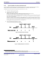
Service Calls from a Handler That Caused an Interrupt during Task Execution .............................................. 15
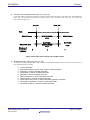
Service Calls from a Handler That Caused an Interrupt during Service Call Processing ................................. 16
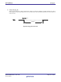
Service Calls from a Handler That Caused an Interrupt during Handler Execution ........................................ 17
3.3
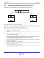
Object.................................................................................................................................................. 18
3.3.1
The specification method of the object in a service call ........................................................... 18
3.4
Task .................................................................................................................................................... 19
3.4.1
Task Status ................................................................................................................................. 19
3.4.2
Task Priority and Ready Queue ................................................................................................ 23
3.4.3
Task Priority and Waiting Queue.............................................................................................. 24
3.4.4
Task Control Block(TCB) ........................................................................................................... 25
3.5
System States..................................................................................................................................... 27
3.5.1
Task Context and Non-task Context ......................................................................................... 27
3.5.2
Dispatch Enabled/Disabled States ............................................................................................ 29
3.5.3
CPU Locked/Unlocked States .................................................................................................... 29
3.5.4
Dispatch Disabled and CPU Locked States.............................................................................. 29
3.6
Regarding Interrupts......................................................................................................................... 30
3.6.1
Types of Interrupt Handlers ...................................................................................................... 30
3.6.2
The Use of Non-maskable Interrupt ......................................................................................... 31
3.6.3
Controlling Interrupts................................................................................................................ 31
3.6.4
Permission and prohibition of interrupt ................................................................................... 33
When prohibiting interrupt in the task ................................................................................................................ 33
When permitting interrupt in the interrupt handler (When accepting multiple interrupt) .............................. 33
3.7
About the power control of M16C and R8C and the operation of the kernel................................. 34
3.8
Stacks ................................................................................................................................................. 35
3.8.1
System Stack and User Stack.................................................................................................... 35
4.
Kernel ..................................................................................................................................................... 36
4.1
4.2
Module Structure............................................................................................................................... 36
Module Overview ............................................................................................................................... 37
II
4.3
Kernel Function ................................................................................................................................. 38
4.3.1
Task Management Function ...................................................................................................... 38
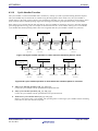
4.3.2
Synchronization functions attached to task ............................................................................. 40
4.3.3
Synchronization and Communication Function (Semaphore)................................................. 44
4.3.4
Synchronization and Communication Function (Eventflag) ................................................... 46
4.3.5
Synchronization and Communication Function (Data Queue) ............................................... 48
4.3.6
Synchronization and Communication Function (Mailbox) ...................................................... 49
4.3.7
Memory pool Management Function(Fixed-size Memory pool) .............................................. 51
4.3.8
Variable-size Memory Pool Management Function.................................................................. 52
4.3.9
Time Management Function...................................................................................................... 54
4.3.10 Cyclic Handler Function ............................................................................................................ 56
4.3.11 Alarm Handler Function............................................................................................................ 57
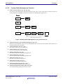
4.3.12 System Status Management Function...................................................................................... 58
4.3.13 Interrupt Management Function .............................................................................................. 59
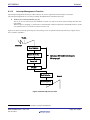
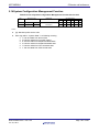
4.3.14 System Configuration Management Function ......................................................................... 60
4.3.15 Extended Function (Long Data Queue) .................................................................................... 61
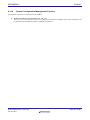
4.3.16 Extended Function (Reset Function) ........................................................................................ 62
5.
Service call reference ............................................................................................................................. 63
5.1
Task Management Function ............................................................................................................. 63
act_tsk
Activate task ........................................................................................................................... 65
iact_tsk Activate task (handler only)................................................................................................... 65
can_act Cancel task activation request............................................................................................... 67
ican_act Cancel task activation request (handler only) ...................................................................... 67
sta_tsk
Activate task with a start code .............................................................................................. 69
ista_tsk Activate task with a start code (handler only)...................................................................... 69
ext_tsk
Terminate invoking task ........................................................................................................ 71
ter_tsk
Terminate task ........................................................................................................................ 73
chg_pri
Change task priority............................................................................................................... 75
ichg_pri Change task priority(handler only) ....................................................................................... 75
get_pri
Reference task priority ........................................................................................................... 77
iget_pri Reference task priority(handler only) ................................................................................... 77
ref_tsk
Reference task status ............................................................................................................. 79
iref_tsk Reference task status (handler only)..................................................................................... 79
ref_tst
Reference task status (simplified version) ............................................................................ 82
iref_tst
Reference task status (simplified version, handler only) ..................................................... 82
5.2
Task Dependent Synchronization Function..................................................................................... 84
slp_tsk
Put task to sleep...................................................................................................................... 85
tslp_tsk Put task to sleep (with timeout)............................................................................................. 85
wup_tsk Wakeup task............................................................................................................................ 87
iwup_tsk
Wakeup task (handler only)................................................................................................ 87
can_wup
Cancel wakeup request ....................................................................................................... 89
ican_wup
Cancel wakeup request (handler only) .............................................................................. 89
rel_wai
Release task from waiting ...................................................................................................... 91
irel_wai Release task from waiting (handler only) ............................................................................. 91
sus_tsk
Suspend task ........................................................................................................................... 93
isus_tsk Suspend task (handler only) .................................................................................................. 93
rsm_tsk Resume suspended task ......................................................................................................... 95
irsm_tsk
Resume suspended task(handler only) .............................................................................. 95
frsm_tsk
Forcibly resume suspended task ........................................................................................ 95
ifrsm_tsk
Forcibly resume suspended task(handler only) ................................................................ 95
dly_tsk
Delay task................................................................................................................................ 97
5.3
Synchronization & Communication Function (Semaphore) ........................................................... 99
sig_sem Release semaphore resource ................................................................................................ 100
isig_sem
Release semaphore resource (handler only) .................................................................... 100
wai_sem
Acquire semaphore resource............................................................................................. 102
pol_sem Acquire semaphore resource (polling) ................................................................................. 102
ipol_sem
Acquire semaphore resource (polling, handler only) ...................................................... 102
twai_sem
Acquire semaphore resource(with timeout)..................................................................... 102
III
ref_sem Reference semaphore status ................................................................................................ 105
iref_sem Reference semaphore status (handler only)........................................................................ 105
5.4
Synchronization & Communication Function (Eventflag)............................................................ 107
set_flg
Set eventflag.......................................................................................................................... 108
iset_flg
Set eventflag (handler only) ................................................................................................. 108
clr_flg Clear eventflag...........................................................................................................................110
iclr_flg
Clear eventflag (handler only) ..............................................................................................110
wai_flg
Wait for eventflag...................................................................................................................112
pol_flg
Wait for eventflag(polling).....................................................................................................112
ipol_flg
Wait for eventflag(polling, handler only)..............................................................................112
twai_flg Wait for eventflag(with timeout)...........................................................................................112
ref_flg
Reference eventflag status ....................................................................................................115
iref_flg
Reference eventflag status (handler only)............................................................................115
5.5
Synchronization & Communication Function (Data Queue) .........................................................117
snd_dtq Send to data queue ................................................................................................................118
psnd_dtq
Send to data queue (polling) ..............................................................................................118
ipsnd_dtq Send to data queue (polling, handler only).......................................................................118
tsnd_dtq
Send to data queue (with timeout)....................................................................................118
fsnd_dtq
Forcibly send to data queue...............................................................................................118
ifsnd_dtq
Forcibly send to data queue (handler only) ......................................................................118
rcv_dtq
Receive from data queue ...................................................................................................... 121
prcv_dtq
Receive from data queue (polling) .................................................................................... 121
iprcv_dtq
Receive from data queue (polling, handler only)............................................................. 121
trcv_dtq Receive from data queue (with timeout) ............................................................................. 121
ref_dtq
Reference data queue status ................................................................................................ 124
iref_dtq Reference data queue status (handler only) ....................................................................... 124
5.6
Synchronization & Communication Function (Mailbox)............................................................... 126
snd_mbx
Send to mailbox ................................................................................................................. 127
isnd_mbx
Send to mailbox (handler only) ........................................................................................ 127
rcv_mbx Receive from mailbox............................................................................................................ 129
prcv_mbx
Receive from mailbox (polling) ......................................................................................... 129
iprcv_mbx Receive from mailbox (polling, handler only) .................................................................. 129
trcv_mbx
Receive from mailbox (with timeout) ............................................................................... 129
ref_mbx Reference mailbox status ..................................................................................................... 132
iref_mbx
Reference mailbox status (handler only) ......................................................................... 132
5.7
Memory Pool Management Function (Fixed-size Memory Pool) .................................................. 134
get_mpf Aquire fixed-size memory block ........................................................................................... 135
pget_mpf
Aquire fixed-size memory block (polling)......................................................................... 135
ipget_mpf Aquire fixed-size memory block (polling, handler only) ................................................. 135
tget_mpf
Aquire fixed-size memory block (with timeout) .............................................................. 135
rel_mpf Release fixed-size memory block.......................................................................................... 138
irel_mpf Release fixed-size memory block (handler only) ................................................................. 138
ref_mpf Reference fixed-size memory pool status ............................................................................ 140
iref_mpf Reference fixed-size memory pool status (handler only).................................................... 140
5.8
Memory Pool Management Function (Variable-size Memory Pool) ............................................. 142
pget_mpl
Aquire variable-size memory block (polling) ................................................................... 143
rel_mpl Release variable-size memory block .................................................................................... 145
ref_mpl Reference variable-size memory pool status ....................................................................... 147
iref_mpl Reference variable-size memory pool status (handler only) .............................................. 147
5.9
Time Management Function........................................................................................................... 149
set_tim
Set system time..................................................................................................................... 150
iset_tim Set system time (handler only) ............................................................................................ 150
get_tim Reference system time.......................................................................................................... 152
iget_tim Reference system time (handler only) ................................................................................. 152
isig_tim Supply a time tick ................................................................................................................. 154
5.10 Time Management Function (Cyclic Handler)............................................................................... 155
sta_cyc
Start cyclic handler operation.............................................................................................. 156
ista_cyc Start cyclic handler operation (handler only) ..................................................................... 156
stp_cyc
Stops cyclic handler operation ............................................................................................. 158
IV
istp_cyc Stops cyclic handler operation (handler only)..................................................................... 158
ref_cyc
Reference cyclic handler status............................................................................................ 159
iref_cyc Reference cyclic handler status (handler only) ................................................................... 159
5.11 Time Management Function (Alarm Handler) .............................................................................. 161
sta_alm Start alarm handler operation ............................................................................................. 162
ista_alm
Start alarm handler operation (handler only)................................................................. 162
stp_alm Stop alarm handler operation .............................................................................................. 164
istp_alm
Stop alarm handler operation (handler only).................................................................. 164
ref_alm Reference alarm handler status........................................................................................... 165
iref_alm Reference alarm handler status (handler only) .................................................................. 165
5.12 System Status Management Function ........................................................................................... 167
rot_rdq
Rotate task precedence......................................................................................................... 168
irot_rdq Rotate task precedence (handler only) ................................................................................ 168
get_tid
Reference task ID in the RUNNING state.......................................................................... 170
iget_tid Reference task ID in the RUNNING state (handler only) ................................................. 170
loc_cpu
Lock the CPU ........................................................................................................................ 172
iloc_cpu Lock the CPU (handler only)................................................................................................ 172
unl_cpu Unlock the CPU .................................................................................................................... 174
iunl_cpu
Unlock the CPU (handler only) ........................................................................................ 174
dis_dsp
Disable dispatching .............................................................................................................. 175
ena_dsp Enables dispatching.............................................................................................................. 177
sns_ctx
Reference context .................................................................................................................. 178
sns_loc
Reference CPU state............................................................................................................. 179
sns_dsp Reference dispatching state ................................................................................................. 180
sns_dpn Reference dispatching pending state................................................................................... 181
5.13 Interrupt Management Function.................................................................................................... 183
ret_int
Returns from an interrupt handler (when written in assembly language)................... 184
5.14 System Configuration Management Function............................................................................... 185
ref_ver
Reference version information ............................................................................................. 186
iref_ver Reference version information (handler only)..................................................................... 186
5.15 Extended Function (Long Data Queue).......................................................................................... 188
vsnd_dtq
Send to Long data queue .................................................................................................. 189
vpsnd_dtq Send to Long data queue (polling).................................................................................... 189
vipsnd_dtq Send to Long data queue (polling, handler only)............................................................ 189
vtsnd_dtq Send to Long data queue (with timeout) ......................................................................... 189
vfsnd_dtq Forcibly send to Long data queue .................................................................................... 189
vifsnd_dtq Forcibly send to Long data queue (handler only)............................................................ 189
vrcv_dtq
Receive from Long data queue ......................................................................................... 192
vprcv_dtq Receive from Long data queue (polling)........................................................................... 192
viprcv_dtq Receive from Long data queue (polling,handler only) .................................................... 192
vtrcv_dtq
Receive from Long data queue (with timeout) ................................................................ 192
vref_dtq Reference Long data queue status....................................................................................... 195
viref_dtq
Reference Long data queue status (handler only)........................................................... 195
5.16 Extended Function (Reset Function).............................................................................................. 197
vrst_dtq Clear data queue area .......................................................................................................... 198
vrst_vdtq
Clear Long data queue area ............................................................................................. 200
vrst_mbx
Clear mailbox area ............................................................................................................ 202
vrst_mpf
Clear fixed-size memory pool area ................................................................................... 204
vrst_mpl
Clear variable-size memory pool area.............................................................................. 205
6.
Applications Development Procedure Overview ................................................................................. 206
6.1
7.
Overview........................................................................................................................................... 206
Detailed Applications ........................................................................................................................... 208
7.1
Program Coding Procedure in C Language.................................................................................... 208
7.1.1
Task Description Procedure ..................................................................................................... 208
7.1.2
Writing a Kernel (OS Dependent) Interrupt Handler.............................................................211
7.1.3
Writing Non-kernel (OS-independent ) Interrupt Handler ................................................... 212
7.1.4
Writing Cyclic Handler/Alarm Handler .................................................................................. 213
V
7.2
Program Coding Procedure in Assembly Language ...................................................................... 214
7.2.1
Writing Task ............................................................................................................................. 214
7.2.2
Writing Kernel(OS-dependent) Interrupt Handler ................................................................ 216
7.2.3
Writing Non-kernel(OS-independent) Interrupt Handler ..................................................... 217
7.2.4
Writing Cyclic Handler/Alarm Handler .................................................................................. 218
7.3
Modifying MR30 Startup Program................................................................................................. 219
7.3.1
C Language Startup Program (crt0mr.a30)............................................................................ 220
7.4
Memory Allocation ........................................................................................................................... 225
7.4.1
Sections that kernel uses ......................................................................................................... 226
Using Configurator .............................................................................................................................. 227
8.
8.1
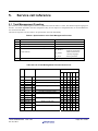
Configuration File Creation Procedure .......................................................................................... 227
8.1.1
Configuration File Data Entry Format................................................................................... 227
Operator ............................................................................................................................................................... 228
Direction of computation ..................................................................................................................................... 228
8.1.2
Configuration File Definition Items........................................................................................ 230
[( System Definition Procedure )] ........................................................................................................................ 230
[( System Clock Definition Procedure )].............................................................................................................. 232
[( Definition respective maximum numbers of items )]...................................................................................... 234
[( Task definition )]............................................................................................................................................... 236
[( Eventflag definition )] ...................................................................................................................................... 238
[( Semaphore definition )] .................................................................................................................................... 239
[(Data queue definition )] .................................................................................................................................... 240
[( Long data queue definition )] ........................................................................................................................... 241
[( Mailbox definition )] ......................................................................................................................................... 242
[( Fixed-size memory pool definition )]................................................................................................................ 243
[( Variable-size memory pool definition )] ........................................................................................................... 245
[( Cyclic handler definition )]............................................................................................................................... 246
[( Alarm handler definition )] .............................................................................................................................. 248
[( Interrupt vector definition )] ............................................................................................................................ 249
8.1.3
Configuration File Example..................................................................................................... 252
8.2
Configurator Execution Procedures ............................................................................................... 256
8.2.1
Configurator Overview............................................................................................................. 256
8.2.2
Setting Configurator Environment ......................................................................................... 258
8.2.3
Configurator Start Procedure .................................................................................................. 258
8.2.4
Precautions on Executing Configurator.................................................................................. 258
8.2.5
Configurator Error Indications and Remedies ....................................................................... 259
Error messages..................................................................................................................................................... 259
Warning messages ............................................................................................................................................... 262
Other messages .................................................................................................................................................... 262
Table Generation Utility ...................................................................................................................... 263
9.
9.1
9.2
9.3
9.4
10.
10.1
10.2
10.3
11.
Summary .......................................................................................................................................... 263
Environment Setup ......................................................................................................................... 263
Table Generation Utility Start Procedure...................................................................................... 263
Notes................................................................................................................................................. 263
Sample Program Description ........................................................................................................... 264
Overview of Sample Program ......................................................................................................... 264
Program Source Listing................................................................................................................... 265
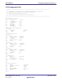
Configuration File............................................................................................................................ 266
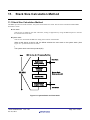
Stack Size Calculation Method ........................................................................................................ 267
11.1 Stack Size Calculation Method ....................................................................................................... 267
11.1.1 User Stack Calculation Method............................................................................................... 269
11.1.2 System Stack Calculation Method .......................................................................................... 271
11.2 Necessary Stack Size ....................................................................................................................... 275
12.
12.1
12.2
Note ................................................................................................................................................... 277
The Use of INT Instruction ............................................................................................................. 277
The Use of registers of bank ........................................................................................................... 277
VI
12.3 Regarding Delay Dispatching ......................................................................................................... 278
12.4 Regarding Initially Activated Task................................................................................................. 279
12.5 Cautions for each microcontrollers................................................................................................. 279
12.5.1 To use the M16C/62 group MCUs............................................................................................ 279
12.5.2 To use the M16C/6N group MCUs........................................................................................... 279
13.
13.1
14.
14.1
14.2
Separate ROMs................................................................................................................................. 280
How to Form Separate ROMs ......................................................................................................... 280
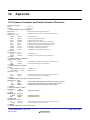
Appendix ........................................................................................................................................... 285
Common Constants and Packet Format of Structure ................................................................... 285
Assembly Language Interface......................................................................................................... 287
VII
List of Figures
Figure 3.1 Relationship between Program Size and Development Period......................................... 5
Figure 3.2 Microcomputer-based System Example(Audio Equipment).............................................. 6
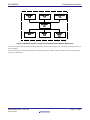
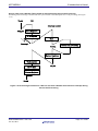
Figure 3.3 Example System Configuration with Real-time OS(Audio Equipment) .......................... 7
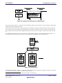
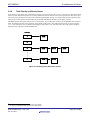
Figure 3.4 Time-division Task Operation ............................................................................................. 8
Figure 3.5 Task Execution Interruption and Resumption .................................................................. 9
Figure 3.6 Task Switching ..................................................................................................................... 9
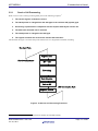
Figure 3.7 Task Register Area ............................................................................................................. 10
Figure 3.8 Actual Register and Stack Area Management ................................................................. 11
Figure 3.9 Service call.......................................................................................................................... 12
Figure 3.10 Service Call Processing Flowchart.................................................................................. 13
Figure 3.11 Processing Procedure for a Service Call a Handler that caused an interrupt during Task
Execution 15
Figure 3.12 Processing Procedure for a Service Call from a Handler that caused an interrupt during
Service Call Processing................................................................................................................. 16
Figure 3.13 Processing Procedure for a service call from a Multiplex interrupt Handler .............. 17
Figure 3.14 Task Identification ........................................................................................................... 18
Figure 3.15 Task Status....................................................................................................................... 19
Figure 3.16 MR30 Task Status Transition ......................................................................................... 20
Figure 3.17 Ready Queue (Execution Queue) .................................................................................... 23
Figure 3.18 Waiting queue of the TA_TPRI attribute ....................................................................... 24
Figure 3.19 Waiting queue of the TA_TFIFO attribute..................................................................... 24
Figure 3.20 Task control block ............................................................................................................ 26
Figure 3.21 Cyclic Handler/Alarm Handler Activation ..................................................................... 28
Figure 3.22 Interrupt handler IPLs.................................................................................................... 30
Figure 3.23 Interrupt control in a Service Call that can be Issued from only a Task ..................... 31
Figure 3.24 Interrupt control in a Service Call that can be Issued from a Task-independent ....... 32
Figure 3.25 System Stack and User Stack ......................................................................................... 35
Figure 4.1 MR30 Structure.................................................................................................................. 36
Figure 4.2 Task Resetting.................................................................................................................... 38
Figure 4.3 Alteration of task priority.................................................................................................. 39
Figure 4.4 Task rearrangement in a waiting queue .......................................................................... 39
Figure 4.5 Wakeup Request Storage................................................................................................... 40
Figure 4.6 Wakeup Request Cancellation........................................................................................... 40
Figure 4.7 Forcible wait of a task and resume................................................................................... 41
Figure 4.8 Forcible wait of a task and forcible resume...................................................................... 42
Figure 4.9 dly_tsk service call ............................................................................................................. 43
Figure 4.10 Exclusive Control by Semaphore .................................................................................... 44
Figure 4.11 Semaphore Counter ......................................................................................................... 44
Figure 4.12 Task Execution Control by Semaphore........................................................................... 45
Figure 4.13 Task Execution Control by the eventflag ....................................................................... 47
Figure 4.14 Data queue ....................................................................................................................... 48
Figure 4.15 Mailbox ............................................................................................................................. 49
Figure 4.16 Message queue ................................................................................................................. 50
Figure 4.17 Memory Pool Management.............................................................................................. 51
Figure 4.18 pget_mpl processing......................................................................................................... 53
Figure 4.19 rel_mpl processing ........................................................................................................... 53
Figure 4.20 Timeout Processing .......................................................................................................... 54
Figure 4.21 Cyclic handler operation in cases where the activation phase is saved ....................... 56
Figure 4.22 Cyclic handler operation in cases where the activation phase is not saved................. 56
Figure 4.23 Typical operation of the alarm handler .......................................................................... 57
Figure 4.24 Ready Queue Management by rot_rdq Service Call ...................................................... 58
Figure 4.25 Interrupt process flow...................................................................................................... 59
VIII
Figure5.1. Manipulation of the ready queue by the rot_rdq service call........................................ 169
Figure 6.1 MR30 System Generation Detail Flowchart .................................................................. 207
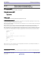
Figure 7.1 Example Infinite Loop Task Described in C Language ................................................. 208
Figure 7.2 Example Task Terminating with ext_tsk() Described in C Language.......................... 209
Figure 7.3 Example of Kernel(OS-dependent) Interrupt Handler.................................................. 211
Figure 7.4 Example of Non-kernel(OS-independent) Interrupt Handler....................................... 212
Figure 7.5 Example Cyclic Handler Written in C Language .......................................................... 213
Figure 7.6 Example Infinite Loop Task Described in Assembly Language.................................... 214
Figure 7.7 Example Task Terminating with ext_tsk Described in Assembly Language ............... 214
Figure 7.8 Example of kernel(OS-depend) interrupt handler......................................................... 216
Figure 7.9 Example of Non-kernel(OS-independent) Interrupt Handler of Specific Level........... 217
Figure 7.10 Example Handler Written in Assembly Language ...................................................... 218
Figure 7.11 C Language Startup Program for M16C/63,64,65(crt0mr.a30)................................... 224
Figure 8.1 The operation of the Configurator .................................................................................. 257
Figure 11.1 System Stack and User Stack ....................................................................................... 267
Figure 11.2 Layout of Stacks ............................................................................................................. 268
Figure 11.3 Example of Use Stack Size Calculation ........................................................................ 270
Figure 11.4 System Stack Calculation Method ................................................................................ 272
Figure 11.5 Stack size to be used by Kernel Interrupt Handler ..................................................... 273
Figure 13.1 ROM separate................................................................................................................. 282
Figure 13.2 Memory map................................................................................................................... 284
IX
List of Tables
Table 3.1 Task Context and Non-task Context................................................................................... 27
Table 3.2 Invocable Service Calls in a CPU Locked State................................................................. 29
Table 3.3 CPU Locked and Dispatch Disabled State Transitions Relating to dis_dsp and loc_cpu29
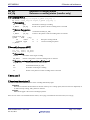
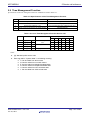
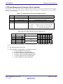
Table 5.1 Specifications of the Task Management Function ............................................................. 63
Table 5.2 List of Task Management Function Service Call............................................................... 63
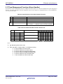
Table 5.3 Specifications of the Task Dependent Synchronization Function .................................... 84
Table 5.4 List of Task Dependent Synchronization Service Call ...................................................... 84
Table 5.5 Specifications of the Semaphore Function ......................................................................... 99
Table 5.6 List of Semaphore Function Service Call ........................................................................... 99
Table 5.7 Specifications of the Eventflag Function.......................................................................... 107
Table 5.8 List of Eventflag Function Service Call ......................................................................... 107
Table 5.9 Specifications of the Data Queue Function ...................................................................... 117
Table 5.10 List of Dataqueue Function Service Call........................................................................ 117
Table 5.11 Specifications of the Mailbox Function........................................................................... 126
Table 5.12 List of Mailbox Function Service Call ............................................................................ 126
Table 5.13 Specifications of the Fixed-size memory pool Function................................................. 134
Table 5.14 List of Fixed-size memory pool Function Service Call .................................................. 134
Table 5.15 Specifications of the Variable-size memory Pool Function............................................ 142
Table 5.16 List of Variable -size memory pool Function Service Call............................................. 142
Table 5.17 Specifications of the Time Management Function......................................................... 149
Table 5.18 List of Time Management Function Service Call .......................................................... 149
Table 5.19 Specifications of the Cyclic Handler Function............................................................. 155
Table 5.20 List of Cyclic Handler Function Service Call ................................................................. 155
Table 5.21 Specifications of the Alarm Handler Function............................................................... 161
Table 5.22 List of Alarm Handler Function Service Call................................................................. 161
Table 5.23 List of System Status Management Function Service Call .......................................... 167
Table 5.24 List of Interrupt Management Function Service Call ................................................... 183
Table 5.25 List of System Configuration Management Function Service Call .............................. 185
Table 5.26 Specifications of the Long Data Queue Function........................................................... 188
Table 5.27 List of Long Dataqueue Function Service Call .............................................................. 188
Table 5.28 List of Reset Function Service Call................................................................................. 197
Table 7.1 C Language Variable Treatment....................................................................................... 210
Table 8.1 Numerical Value Entry Examples .................................................................................... 228
Table 8.2 Operators ............................................................................................................................ 228
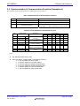
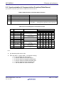
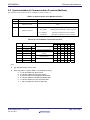
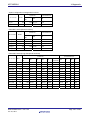
Table 8.3 Interrupt Causes and Vector Numbers............................................................................. 251
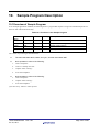
Table 10.1 Functions in the Sample Program .................................................................................. 264
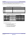
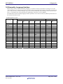
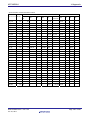
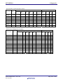
Table 11.1 Stack Sizes Used by Service Calls Issued from Tasks (in bytes) .................................. 275
Table 11.2 Stack Sizes Used by Service Calls Issued from Handlers (in bytes)............................. 276
Table 11.3 Stack Sizes Used by Service Calls Issued from Tasks and Handlers (in bytes) .......... 276
Table 12.1 Interrupt Number Assignment ....................................................................................... 277
x
1.
User’s Manual Organization
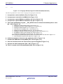
The MR30 User’s Manual consists of nine chapters and thee appendix.
•
•
•
•
•
•
•
•
•
•
•
•
•
2 General Information
Outlines the objective of MR30 development and the function and position of the MR30.
3 Introduction to Kernel
Explains about the ideas involved in MR30 operations and defines some relevant terms.
4 Kernel
Outlines the applications program development procedure for the MR30.
5 Service call reference
Details MR30 service call API.
6 Applications Development Procedure Overview
Details the applications program development procedure for the MR30.
7 Detailed Applications
Presents useful information and precautions concerning applications program development with MR30.
8 Using Configurator
Describes the method for writing a configuration file and the method for using the configurator in detail.
9 Table Generation Utility
Describes the method for executing table generation utility in detail.
10 Sample Program Description
Describes the MR30 sample applications program which is included in the product in the form of a source file.
11 Stack Size Calculation Method
Describes the calculation method of the task stack size and the system stack size.
12 Note
Presents useful information and precautions concerning applications program development with MR30.
13 Separate ROMs
Explains about how to Form Separate ROMs.
14 Appendix
Data type and assembly language interface.
R20UT0655EJ0100 Rev.1.00
Jun 01, 2011
Page 1 of 295
2.
General Information
2.1 Objective of MR30 Development
In line with recent rapid technological advances in microcomputers, the functions of microcomputer-based products have
become complicated. In addition, the microcomputer program size has increased. Further, as product development competition has been intensified, manufacturers are compelled to develop their microcomputer-based products within a short
period of time.
In other words, engineers engaged in microcomputer software development are now required to develop larger-size programs within a shorter period of time. To meet such stringent requirements, it is necessary to take the following considerations into account.
1. To enhance software recyclability to decrease the volume of software to be developed.
One way to provide for software recyclability is to divide software into a number of functional modules wherever possible. This may be accomplished by accumulating a number of general-purpose subroutines and other
program segments and using them for program development. In this method, however, it is difficult to reuse
programs that are dependent on time or timing. In reality, the greater part of application programs are dependent
on time or timing. Therefore, the above recycling method is applicable to only a limited number of programs.
2. To promote team programming so that a number of engineers are engaged in the development of one software package
There are various problems with team programming. One major problem is that debugging can be initiated only
when all the software program segments created individually by team members are ready for debugging. It is
essential that communication be properly maintained among the team members.
3. To enhance software production efficiency so as to increase the volume of possible software
development per engineer.
One way to achieve this target would be to educate engineers to raise their level of skill. Another way would be
to make use of a structured descriptive assembler, C-compiler, or the like with a view toward facilitating programming. It is also possible to enhance debugging efficiency by promoting modular software development.
However, the conventional methods are not adequate for the purpose of solving the problems. Under these circumstances,
it is necessary to introduce a new system named real-time OS 3
To answer the above-mentioned demand, Renesas has developed a real-time operating system, tradenamed MR30, for use
with the M16C/10, M16C/20, M16C/30, M16C/60 ,M16C/Tiny and R8C/Tiny series of 16-bit microcomputers .
When the MR30 is introduced, the following advantages are offered.
1. Software recycling is facilitated.
When the real-time OS is introduced, timing signals are furnished via the real-time OS so that programs dependent on timing can be reused. Further, as programs are divided into modules called tasks, structured programming will be spontaneously provided.
That is, recyclable programs are automatically prepared.
3
OS:Operating System
R20UT0655EJ0100 Rev.1.00
Jun 01, 2011
Page 2 of 295
M3T-MR30/4
2 General Information
2. Ease of team programming is provided.
When the real-time OS is put to use, programs are divided into functional modules called tasks. Therefore, engineers can be allocated to individual tasks so that all steps from development to debugging can be conducted
independently for each task.
Further, the introduction of the real-time OS makes it easy to start debugging some already finished tasks even
if the entire program is not completed yet. Since engineers can be allocated to individual tasks, work assignment is easy.
3. Software independence is enhanced to provide ease of program debugging.
As the use of the real-time OS makes it possible to divide programs into small independent modules called
tasks, the greater part of program debugging can be initiated simply by observing the small modules.
4. Timer control is made easier.
To perform processing at 10 ms intervals, the microcomputer timer function was formerly used to periodically
initiate an interrupt. However, as the number of usable microcomputer timers was limited, timer insufficiency
was compensated for by, for instance, using one timer for a number of different processing operations.
When the real-time OS is introduced, however, it is possible to create programs for performing processing at
fixed time intervals making use of the real-time OS time management function without paying special attention
to the microcomputer timer function. At the same time, programming can also be done in such a manner as to
let the programmer take that numerous timers are provided for the microcomputer.
5. Software maintainability is enhanced
When the real-time OS is put to use, the developed software consists of small program modules called tasks.
Therefore, increased software maintainability is provided because developed software maintenance can be carried out simply by maintaining small tasks.
6. Increased software reliability is assured.
The introduction of the real-time OS makes it possible to carry out program evaluation and testing in the unit of
a small module called task. This feature facilitates evaluation and testing and increases software reliability.
7. The microcomputer performance can be optimized to improve the performance of microcomputer-based products.
With the real-time OS, it is possible to decrease the number of unnecessary microcomputer operations such as
I/O waiting. It means that the optimum capabilities can be obtained from microcomputers, and this will lead to
microcomputer-based product performance improvement.
R20UT0655EJ0100 Rev.1.00
Jun 01, 2011
Page 3 of 295
M3T-MR30/4
2 General Information
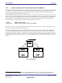
2.2 Relationship between TRON Specification and MR30
MR30 is the real-time operating system developed for use with the M16C/10, M16C/20, M16C/30, M16C/60,
M16C/Tiny and R8C/Tiny series of 16-bit microcomputers compliant with µITRON 4.0 Specification. µITRON 4.0
Specification stipulates standard profiles as an attempt to ensure software portability. Of these standard profiles,
MR30 has implemented in it all service calls except for static APIs and task exception APIs.
2.3 MR30 Features
The MR30 offers the following features.
1. Real-time operating system conforming to the μITRON Specification.
The MR30 is designed in compliance with the μITRON Specification which incorporates a minimum of the
ITRON Specification functions so that such functions can be incorporated into a one-chip microcomputer. As
the μITRON Specification is a subset of the ITRON Specification, most of the knowledge obtained from published ITRON textbooks and ITRON seminars can be used as is.
Further, the application programs developed using the real-time operating systems conforming to the ITRON
Specification can be transferred to the MR30 with comparative ease.
2. High-speed processing is achieved.
MR30 enables high-speed processing by taking full advantage of the microcomputer architecture.
3. Only necessary modules are automatically selected to constantly build up a system of the
minimum size.
MR30 is supplied in the object library format of the M16C/10, M16C/20, M16C/30, M16C/60 ,M16C/Tiny and
R8C/Tiny series.
Therefore, the Linkage Editor LN30 functions are activated so that only necessary modules are automatically
selected from numerous MR30 functional modules to generate a system.
Thanks to this feature, a system of the minimum size is automatically generated at all times.
4. With the C-compiler NC30WA, it is possible to develop application programs in C language.
Application programs of MR30 can be developed in C language by using the C compiler NC30WA. Furthermore, the interface library necessary to call the MR30 functions from C language is included with the software
package.
5. An upstream process tool named "Configurator" is provided to simplify development procedures
A configurator is furnished so that various items including a ROM write form file can be created by giving simple definitions.
Therefore, there is no particular need to care what libraries must be linked.
In addition, a GUI version of the configurator is available beginning with M3T-MR30/4 V.4.00. It helps the user
to create a configuration file without the need to learn how to write it.
R20UT0655EJ0100 Rev.1.00
Jun 01, 2011
Page 4 of 295
3.
Introduction to Kernel
3.1 Concept of Real-time OS
This section explains the basic concept of real-time OS.
3.1.1
Why Real-time OS is Necessary
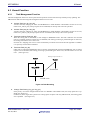
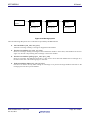
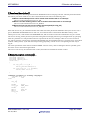
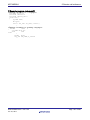
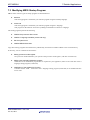
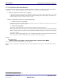
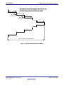
In line with the recent advances in semiconductor technologies, the single-chip microcomputer ROM capacity has increased. ROM capacity of 32K bytes.
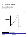
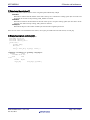
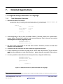
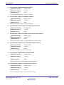
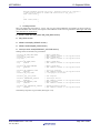
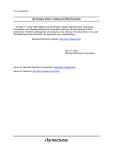
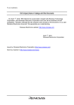
As such large ROM capacity microcomputers are introduced, their program development is not easily carried out by conventional methods. Figure 3.1 shows the relationship between the program size and required development time (program
development difficulty).
This figure is nothing more than a schematic diagram. However, it indicates that the development period increases exponentially with an increase in program size.
For example, the development of four 8K byte programs is easier than the development of one 32K byte program. 4
Development Period
4
8
16
32
Kbyte
Program Size
Figure 3.1 Relationship between Program Size and Development Period
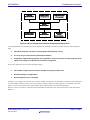
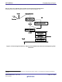
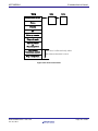
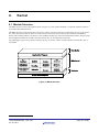
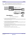
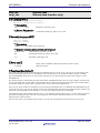
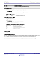
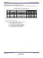
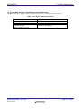
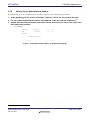
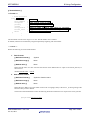
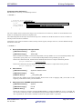
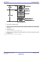
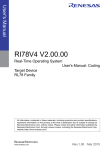
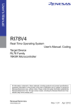
Under these circumstances, it is necessary to adopt a method by which large-size programs can be developed within a
short period of time. One way to achieve this purpose is to use a large number of microcomputers having a small ROM
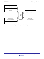
capacity. Figure 3.2 presents an example in which a number of microcomputers are used to build up an audio equipment
system.
4
On condition that the ROM program burning step need not be performed.
R20UT0655EJ0100 Rev.1.00
Jun 01, 2011
Page 5 of 295
M3T-MR30/4
3 Introduction to Kernel
Key input
microcomputer
Remote control
microcomputer
LED illumination
microcomputer
Arbiter
microcomputer
Volume control
microcomputer
Monitor
microcomputer
Mechanical
control
microcomputer
Figure 3.2 Microcomputer-based System Example(Audio Equipment)
Using independent microcomputers for various functions as indicated in the above example offers the following advantages.
1. Individual programs are small so that program development is easy.
2. It is very easy to use previously developed software.
3. Completely independent programs are provided for various functions so that program development can easily be conducted by a number of engineers.
On the other hand, there are the following disadvantages.
1. The number of parts used increases, thereby raising the product cost.
2. Hardware design is complicated.
3. Product physical size is enlarged.
Therefore, if you employ the real-time OS in which a number of programs to be operated by a number of microcomputers
are placed under software control of one microcomputer, making it appear that the programs run on separate microcomputers, you can obviate all the above disadvantages while retaining the above-mentioned advantages.
Figure 3.3 shows an example system that will be obtained if the real-time OS is incorporated in the system indicated in
Figure 3.2.
R20UT0655EJ0100 Rev.1.00
Jun 01, 2011
Page 6 of 295
M3T-MR30/4
3 Introduction to Kernel
Key input
Task
Remote control
Task
LED illumination
Task
real-time
OS
Volume control
Task
Monitor
Task
Mechanical
control
Task
Figure 3.3 Example System Configuration with Real-time OS(Audio Equipment)
In other words, the real-time OS is the software that makes a one-microcomputer system look like operating a number of
microcomputers.
In the real-time OS, the individual programs, which correspond to a number of microcomputers used in a conventional
system, are called tasks.
R20UT0655EJ0100 Rev.1.00
Jun 01, 2011
Page 7 of 295
M3T-MR30/4
3.1.2
3 Introduction to Kernel
Operating Principles of Kernel
A kernel is the core program of real-time OS. The kernel is the software that makes a one-microcomputer system look
like operating a number of microcomputers. You should be wondering how the kernel makes a one-microcomputer system function like a number of microcomputers.
As shown in Figure 3.4 the kernel runs a number of tasks according to the time-division system. That is, it changes the
task to execute at fixed time intervals so that a number of tasks appear to be executed simultaneously.
Key input
Task
Remote control
Task
LED
illumination
Task
Volume control
Task
Monitor
Task
Mechanical
control
Task
Time
Figure 3.4 Time-division Task Operation
As indicated above, the kernel changes the task to execute at fixed time intervals. This task switching may also be referred to as dispatching. The factors causing task switching (dispatching) are as follows.
•
Task switching occurs upon request from a task.
•
Task switching occurs due to an external factor such as interrupt.
When a certain task is to be executed again upon task switching, the system resumes its execution at the point of last interruption (See Figure 3.5).
R20UT0655EJ0100 Rev.1.00
Jun 01, 2011
Page 8 of 295
M3T-MR30/4
3 Introduction to Kernel
Key input
Task
Remote control
Task
Program execution
interrupt
Program execution
resumed
During this interval, it
appears that the key input
microcomputer is haled.
Figure 3.5 Task Execution Interruption and Resumption
In the state shown in Figure 3.5, it appears to the programmer that the key input task or its microcomputer is halted while
another task assumes execution control.
Task execution restarts at the point of last interruption as the register contents prevailing at the time of the last interruption are recovered. In other words, task switching refers to the action performed to save the currently executed task register contents into the associated task management memory area and recover the register contents for the task to switch
to.
To establish the kernel, therefore, it is only necessary to manage the register for each task and change the register contents upon each task switching so that it looks as if a number of microcomputers exist (See Figure 3.6).
R0
R1
Actual
Register
PC
Kernel
Key input
Task
Remote control
Task
R0
R0
R1
R1
PC
PC
Register
Register
Figure 3.6 Task Switching
The example presented in Figure 3.7 5 indicates how the individual task registers are managed. In reality, it is necessary
to provide not only a register but also a stack area for each task.
5
It is figure where all the stack areas of the task were arranged in the same section.
R20UT0655EJ0100 Rev.1.00
Jun 01, 2011
Page 9 of 295
M3T-MR30/4
3 Introduction to Kernel
Memory map
Register
R0
Remote control
Task
PC
SP
R0
Key input
Task
Stack
section
PC
SP
R0
LED illumination
Task
PC
SP
Real-time
OS
SP
SFR
Figure 3.7 Task Register Area
Figure 3.8 shows the register and stack area of one task in detail. In the MR30, the register of each task is stored in a
stack area as shown in Figure 3.8. This figure shows the state prevailing after register storage.
R20UT0655EJ0100 Rev.1.00
Jun 01, 2011
Page 10 of 295
M3T-MR30/4
3 Introduction to Kernel
SP
Register not stored
PC
FLG
FB
SB
A1
A0
Key input task
stack
R3
R2
Key input
Task
R1
SP
R0
Register stored
SFR
Figure 3.8 Actual Register and Stack Area Management
R20UT0655EJ0100 Rev.1.00
Jun 01, 2011
Page 11 of 295
M3T-MR30/4
3 Introduction to Kernel
3.2 Service Call
How does the programmer use the kernel functions in a program?
First, it is necessary to call up kernel function from the program in some way or other. Calling a kernel function is referred to as a service call. Task activation and other processing operations can be initiated by such a service call (See
Figure 3.9).
Kernel
Key input
Task
Service call
Remote control
task
Task switching
Figure 3.9 Service call
This service call is realized by a function call when the application program is written in C language, as shown below.
act_tsk(ID_main,3);
Furthermore, if the application program is written in assembly language, it is realized by an assembler macro call, as
shown below.
act_tsk #ID_main
R20UT0655EJ0100 Rev.1.00
Jun 01, 2011
Page 12 of 295
M3T-MR30/4
3.2.1
3 Introduction to Kernel
Service Call Processing
When a service call is issued, processing takes place in the following sequence. 6
1. The current register contents are saved.
2. The stack pointer is changed from the task type to the real-time OS (system) type.
3. Processing is performed in compliance with the request made by the service call.
4. The task to be executed next is selected.
5. The stack pointer is changed to the task type.
6. The register contents are recovered to resume task execution.
The flowchart in Figure 3.10 shows the process between service call generation and task switching.
Key input Task
Register Save
Service call issuance
SP <= OS
Processing
Task Selection
Task => SP
LED illumination Task
Register Restore
Figure 3.10 Service Call Processing Flowchart
6
A different sequence is followed if the issued service call does not evoke task switching.
R20UT0655EJ0100 Rev.1.00
Jun 01, 2011
Page 13 of 295
M3T-MR30/4
3.2.2
3 Introduction to Kernel
Processing Procedures for Service Calls from Handlers
When a service call is issued from a handler, task switching does not occur unlike in the case of a service call from a task.
However, task switching occurs when a return from a handler 7 is made.
The processing procedures for service calls from handlers are roughly classified into the following three types.
1. A service call from a handler that caused an interrupt during task execution
2. A service call from a handler that caused an interrupt during service call processing
3. A service call from a handler that caused an interrupt (multiplex interrupt) during handler execution
7
The service call can't be issued from OS-independent handler. Therefore, The handler described here does not include the
OS-independent handler.
R20UT0655EJ0100 Rev.1.00
Jun 01, 2011
Page 14 of 295
M3T-MR30/4
3 Introduction to Kernel
Service Calls from a Handler That Caused an Interrupt during Task Execution
Scheduling (task switching) is initiated by the ret_int service call 8(See Figure 3.11).
TaskA
Interrupt handler
OS
Interrupt
Save Registers
iset_flg
Service call processing
Restore Registers
ret_int
Task selection
SP <= User
TaskB
Scheduler
Restore Registers
Figure 3.11 Processing Procedure for a Service Call a Handler that caused an interrupt during Task
Execution
8
The ret_int service call is issued automatically when OS-dependent handler is written in C language (when #pragma INTHANDLER
specified)
R20UT0655EJ0100 Rev.1.00
Jun 01, 2011
Page 15 of 295
M3T-MR30/4
3 Introduction to Kernel
Service Calls from a Handler That Caused an Interrupt during Service Call Processing
Scheduling (task switching) is initiated after the system returns to the interrupted service call processing (See Figure
3.12).
TaskA
OS
Interrupt handler
wup_tsk
Save Registers
SP <= System
Save
Interrupt
iset_flg
Service call processing
Restore Registers
Task selection
SP <= User
ret_int
Restore Registers
TaskB
Figure 3.12 Processing Procedure for a Service Call from a Handler that caused an interrupt during
Service Call Processing
R20UT0655EJ0100 Rev.1.00
Jun 01, 2011
Page 16 of 295
M3T-MR30/4
3 Introduction to Kernel
Service Calls from a Handler That Caused an Interrupt during Handler Execution
Let us think of a situation in which an interrupt occurs during handler execution (this handler is hereinafter referred to as
handler A for explanation purposes). When task switching is called for as a handler (hereinafter referred to as handler B)
that caused an interrupt during handler A execution issued a service call, task switching does not take place during the
execution of the service call (ret_int service call) returned from handler B, but is effected by the ret_int service call from
handler A (See Figure 3.13).
TaskA
Interrupt handler A
Interrupt handler A
Interrupt
Save Registers
OS
SP <= System
Save Registers
Interrupt
iset_flg
Restore Register
Service call processing
Restore Register
ret_int
Task selection
ret_int
SP <= User
Restore Registers
TaskB
Figure 3.13 Processing Procedure for a service call from a Multiplex interrupt Handler
R20UT0655EJ0100 Rev.1.00
Jun 01, 2011
Page 17 of 295
M3T-MR30/4
3 Introduction to Kernel
3.3 Object
The object operated by the service call of a semaphore, a task, etc. is called an "object." An object is identified by the ID
number
3.3.1
The specification method of the object in a service call
Each task is identified by the ID number internally in MR30.
For example, the system says, "Start the task having the task ID number 1."
However, if a task number is directly written in a program, the resultant program would be very low in readability. If, for
instance, the following is entered in a program, the programmer is constantly required to know what the No. 2 task is.
act_tsk(2);
Further, if this program is viewed by another person, he/she does not understand at a glance what the No. 2 task is. To
avoid such inconvenience, the MR30 provides means of specifying the task by name (function or symbol name).
The program named "configurator cfg30 ,"which is supplied with the MR30, then automatically converts the task name
to the task ID number. This task identification system is schematized in Figure 3.14.
sta_tsk(Task name)
Name
ID number
Starting the task
having the designated
ID number
Configurator
Program
Real-time OS
Figure 3.14 Task Identification
act_tsk(ID_task);
This example specifies that a task corresponding to "ID_task" be invoked.
It should also be noted that task name-to-ID number conversion is effected at the time of program generation. Therefore,
the processing speed does not decrease due to this conversion feature.
R20UT0655EJ0100 Rev.1.00
Jun 01, 2011
Page 18 of 295
M3T-MR30/4
3 Introduction to Kernel
3.4 Task
This section describes how tasks are managed by MR30.
3.4.1
Task Status
The real-time OS monitors the task status to determine whether or not to execute the tasks.
Figure 3.15 shows the relationship between key input task execution control and task status. When there is a key input,
the key input task must be executed. That is, the key input task is placed in the execution (RUNNING) state. While the
system waits for key input, task execution is not needed. In that situation, the key input task in the WAITING state.
Key input
Task
Key input
processing
Waiting for
key input
RUNNIG state
WAITING state
Key input
processing
RUNNING state
Figure 3.15 Task Status
The MR30 controls the following six different states including the RUNNING and WAITING states.
1. RUNNING state
2. READY state
3. WAITING state
4. SUSPENDED state
5. WAITING-SUSPENDED state
6. DORMANT state
Every task is in one of the above six different states. Figure 3.16 shows task status transition.
R20UT0655EJ0100 Rev.1.00
Jun 01, 2011
Page 19 of 295
M3T-MR30/4
3 Introduction to Kernel
MPU execlusive right acquisition
READY state
RUNNING state
MPU execlusive right relinquishment
WAITING
l
Entering the
WAITING state
state
WAITING state
SUSPENDED state clear
request from other task
SUSPEND request
from other task
Force d
termination
re quest
from other
task
Terminate
task self
WAITING-SUSPENDED
state
SUSPEND request
from other task
SUSPENDED state
clear request
Forced termination
request from other task
WAITING
clear
t
state
SUSPENDED
state
DORMANT
state
Task activation
Figure 3.16 MR30 Task Status Transition
1. RUNNING state
In this state, the task is being executed. Since only one microcomputer is used, it is natural that only one task is
being executed.
The currently executed task changes into a different state when any of the following conditions occurs.
♦
♦
♦
♦
♦
♦
The task has normally terminated itself by ext_tsk service call.
The task has placed itself in the WAITING. 9
Since the service call was issued from the RUNNING state task, the WAITING state of another task with a priority higher than the RUNNING state task is cleared.
Due to interruption or other event occurrence, the interrupt handler has placed a different
task having a higher priority in the READY state.
The priority assigned to the task has been changed by chg_pri or ichg_pri service call so
that the priority of another READY task is rendered higher.
When the ready queue of the issuing task priority is rotated by the rot_rdq or irot_rdq service call and control of execution is thereby abandoned
When any of the above conditions occurs, rescheduling takes place so that the task having the highest priority
among those in the RUNNING or READY state is placed in the RUNNING state, and the execution of that task
starts.
2. READY state
The READY state refers to the situation in which the task that meets the task execution conditions is still waiting for execution because a different task having a higher priority is currently being executed.
9
By issuing dly_tsk, slp_tsk, tslp_tsk, wai_flg, twai_flg, wai_sem, twai_sem, rcv_mbx, trcv_mbx,snd_dtq,tsnd_dtq,rcv_dtq, trcv_dtq,
vtsnd_dtq, vsnd_dtq,vtrcv_dtq,vrcv_dtq, get_mpf and tget_mpf service call.
R20UT0655EJ0100 Rev.1.00
Jun 01, 2011
Page 20 of 295
M3T-MR30/4
3 Introduction to Kernel
When any of the following conditions occurs, the READY task that can be executed second according to the
ready queue is placed in the RUNNING state.
♦
♦
♦
♦
♦
A currently executed task has normally terminated itself by ext_tsk service call.
A currently executed task has placed itself in the WAITING state. 10
A currently executed task has changed its own priority by chg_pri or ichg_pri service call so
that the priority of a different READY task is rendered higher.
Due to interruption or other event occurrence, the priority of a currently executed task has
been changed so that the priority of a different READY task is rendered higher.
When the ready queue of the issuing task priority is rotated by the rot_rdq or irot_rdq service call and control of execution is thereby abandoned
3. WAITING state
When a task in the RUNNING state requests to be placed in the WAITING state, it exits the RUNNING state
and enters the WAITING state. The WAITING state is usually used as the condition in which the completion of
I/O device I/O operation or the processing of some other task is awaited.
The task goes into the WAITING state in one of the following ways.
♦
♦
♦
♦
♦
z
z
z
z
z
z
z
z
The task enters the WAITING state simply when the slp_tsk service call is issued. In this
case, the task does not go into the READY state until its WAITING state is cleared explicitly
by some other task.
The task enters and remains in the WAITING state for a specified time period when the
dly_tsk service call is issued. In this case, the task goes into the READY state when the
specified time has elapsed or its WAITING state is cleared explicitly by some other task.
The task is placed into WAITING state for a wait request by the wai_flg, wai_sem, rcv_mbx,
snd_dtq, rcv_dtq, vsnd_dtq, vrcv_dtq, or get_mpf service call. In this case, the task goes
from WAITING state to READY state when the request is met or WAITING state is explicitly
canceled by another task.
The tslp_tsk, twai_flg, twai_sem, trcv_mbx, tsnd_dtq, trcv_dtq, vtsnd_dtq, vtrcv_dtq, and
tget_mpf service calls are the timeout-specified versions of the slp_tsk, wai_flg, wai_sem,
rcv_mbx, snd_dtq, rcv_dtq, vsnd_dtq, vrcv_dtq, and get_mpf service calls. The task is
placed into WAITING state for a wait request by one of these service calls. In this case, the
task goes from WAITING state to READY state when the request is met or the specified
time has elapsed.
If the task is placed into WAITING state for a wait request by the wai_flg, wai_sem, rcv_mbx,
snd_dtq, rcv_dtq, vsnd_dtq, vrcv_dtq, get_mpf, twai_flg, twai_sem, trcv_mbx, tsnd_dtq,
trcv_dtq, vtsnd_dtq, vtrcv_dtq, or tget_mpf service call, the task is queued to one of the following waiting queues depending on the request.
Event flag waiting queue
Semaphore waiting queue
Mailbox message reception waiting queue
Data queue data transmission waiting queue
Data queue data reception waiting queue
Short data queue data transmission waiting queue
Short data queue data reception waiting queue
Fixed-size memory pool acquisition waiting queue
4. SUSPENDED state
When the sus_tsk service call is issued from a task in the RUNNING state or the isus_tsk service call is issued
from a handler, the READY task designated by the service call or the currently executed task enters the SUSPENDED state. If a task in the WAITING state is placed in this situation, it goes into the WAITING-SUSPENDED state.
10
Depends on the dly_tsk, slp_tsk, tslp_tsk, wai_flg, twai_flg, wai_sem, twai_sem, rcv_mbx, trcv_mbx,snd_dtq,tsnd_dtq,rcv_dtq, trcv_dtq,
vtsnd_dtq, vsnd_dtq,vtrcv_dtq,tget_mpf, get_mpf or vrcv_dtq service call.
R20UT0655EJ0100 Rev.1.00
Jun 01, 2011
Page 21 of 295
M3T-MR30/4
3 Introduction to Kernel
The SUSPENDED state is the condition in which a READY task or currently executed task 11 is excluded from
scheduling to halt processing due to I/O or other error occurrence. That is, when the suspend request is made to
a READY task, that task is excluded from the execution queue.
Note that no queue is formed for the suspend request. Therefore, the suspend request can only be made to the
tasks in the RUNNING, READY, or WAITING state. 12 If the suspend request is made to a task in the SUSPENDED state, an error code is returned.
5. WAITING-SUSPENDED
If a suspend request is issued to a task currently in a WAITING state, the task goes to a WAITING-SUSPENDED state. If a suspend request is issued to a task that has been placed into a WAITING state for
a wait request by the slp_tsk, dly_tsk, wai_flg, wai_sem, rcv_mbx, snd_dtq, rcv_dtq, vsnd_dtq, vrcv_dtq,
get_mpf, tslp_tsk, twai_flg, twai_sem, trcv_mbx, tsnd_dtq, trcv_dtq, vtsnd_dtq, vtrcv_dtq, or tget_mpf service
call, the task goes to a WAITING-SUSPENDED state.
When the wait condition for a task in the WAITING-SUSPENDED state is cleared, that task goes into the SUSPENDED state. It is conceivable that the wait condition may be cleared, when any of the following conditions
occurs.
♦
♦
♦
♦
The task wakes up upon wup_tsk, or iwup_tsk service call issuance.
The task placed in the WAITING state by the dly_tsk or tslp_tsk service call wakes up after
the specified time elapse.
The request of the task placed in the WAITING state by the wai_flg , wai_sem, rcv_mbx,
snd_dtq, rcv_dtq, vsnd_dtq, vrcv_dtq, get_mpf, tslp_tsk, twai_flg, twai_sem, trcv_mbx,
tsnd_dtq, trcv_dtq, vtsnd_dtq, vtrcv_dtq, or tget_mpf service call is fulfilled.
The WAITING state is forcibly cleared by the rel_wai or irel_wai service call
When the SUSPENDED state clear request by rsm_tsk or irsm_tsk is made to a task in the WAITING-SUSPENDED state, that task goes into the WAITING state. Since a task in the SUSPENDED state cannot
request to be placed in the WAITING state, status change from SUSPENDED to WAITING-SUSPENDED does
not possibly occur.
6. DORMANT
This state refers to the condition in which a task is registered in the MR30 system but not activated. This task
state prevails when either of the following two conditions occurs.
♦
♦
The task is waiting to be activated.
The task is normally terminated by ext_tsk service call or forcibly terminated by ter_tsk service call.
11
If the task under execution is placed into a forcible wait state by the isus_tsk service call from the handler, the task goes from an executing state directly to a forcible wait state. Please note that in only this case exceptionally, it is possible that a task will go from an executing state directly to a forcible wait state.
12
If a forcible wait request is issued to a task currently in a wait state, the task goes to a WAITING-SUSPENDED state.
R20UT0655EJ0100 Rev.1.00
Jun 01, 2011
Page 22 of 295
M3T-MR30/4
3.4.2
3 Introduction to Kernel
Task Priority and Ready Queue
In the kernel, several tasks may simultaneously request to be executed. In such a case, it is necessary to determine which
task the system should execute first. To properly handle this kind of situation, the system organizes the tasks into proper
execution priority and starts execution with a task having the highest priority. To complete task execution quickly, tasks
related to processing operations that need to be performed immediately should be given higher priorities.
The MR30 permits giving the same priority to several tasks. To provide proper control over the READY task execution
order, the kernel generates a task execution queue called "ready queue." The ready queue structure is shown in Figure
3.17 13 The ready queue is provided and controlled for each priority level. The first task in the ready queue having the
highest priority is placed in the RUNNING state. 14
Priority
1
TCB
2
3
TCB
TCB
n
TCB
TCB
TCB
Figure 3.17 Ready Queue (Execution Queue)
13
14
The TCB(task control block is described in the next chapter.)
The task in the RUNNING state remains in the ready queue.
R20UT0655EJ0100 Rev.1.00
Jun 01, 2011
Page 23 of 295
M3T-MR30/4
3.4.3
3 Introduction to Kernel
Task Priority and Waiting Queue
In The standard profiles in µITRON 4.0 Specification support two waiting methods for each object. In one method, tasks
are placed in a waiting queue in order of priority (TA_TPRI attribute); in another, tasks are placed in a waiting queue in
order of FIFO (TA_TFIFO).
Figure 3.18 and Figure 3.19 depict the manner in which tasks are placed in a waiting queue in order of "taskD,"
"taskC," "taskA," and "taskB."
ID No.
1
2
n
taskA
taskB
taskC
taskD
Priority 1
Priority 5
Priority 6
Priority 9
Figure 3.18 Waiting queue of the TA_TPRI attribute
ID No.
1
2
n
taskD
taskC
taskA
taskB
Priority 9
Priority 6
Priority 1
Priority 5
Figure 3.19 Waiting queue of the TA_TFIFO attribute
R20UT0655EJ0100 Rev.1.00
Jun 01, 2011
Page 24 of 295
M3T-MR30/4
3.4.4
3 Introduction to Kernel
Task Control Block(TCB)
The task control block (TCB) refers to the data block that the real-time OS uses for individual task status, priority, and
other control purposes.
The MR30 manages the following task information as the task control block
•
Task connection pointer
Task connection pointer used for ready queue formation or other purposes.
•
Task status
•
Task priority
•
Task register information and other data 15 storage stack area pointer(current SP register value)
•
•
•
•
•
•
•
Wake-up counter
Task wake-up request storage area.
Time-out counter or wait flag pattern
When a task is in a time-out wait state, the remaining wait time is stored; if in a flag wait state, the flag's wait
pattern is stored in this area.
Flag wait mode
This is a wait mode during eventflag wait.
Timer queue connection pointer
This area is used when using the timeout function. This area stores the task connection pointer used when constructing the timer queue.
Flag wait pattern
This area is used when using the timeout function.
This area stores the flag wait pattern when using the eventflag wait service call with the timeout function
(twai_flg). No flag wait pattern area is allocated when the eventflag is not used.
Startup request counter
This is the area in which task startup requests are accumulated.
Extended task information
Extended task information that was set during task generation is stored in this area.
The task control block is schematized in Figure 3.20.
15
Called the task context
R20UT0655EJ0100 Rev.1.00
Jun 01, 2011
Page 25 of 295
M3T-MR30/4
3 Introduction to Kernel
TCB
TCB
TCB
Task Connection pointer
Status
Priority
SP
Wake-up counter
Flag wait mode
Time-out counter
or
Flag wait pattern
Timer queue
Connection pointer
This area is allocated only when
the timeout function is used.
Flag wait pattern
Figure 3.20 Task control block
R20UT0655EJ0100 Rev.1.00
Jun 01, 2011
Page 26 of 295
M3T-MR30/4
3 Introduction to Kernel
3.5 System States
3.5.1
Task Context and Non-task Context
The system runs in either context state, "task context" or "non-task context." The differences between the task content
and non-task context are shown in Table 3-1. Task Context and Non-task Context.
Table 3.1 Task Context and Non-task Context
Task context
Non-task context
Invocable service call
Those that can be invoked from
task context
Those that can be invoked from
non-task context
Task scheduling
Occurs when the queue state has
changed to other than dispatch disabled and CPU locked states.
It does not occur.
Stack
User stack
System stack
The processes executed in non-task context include the following.
1. Interrupt Handler
A program that starts upon hardware interruption is called the interrupt handler. The MR30 is not concerned in interrupt
handler activation. Therefore, the interrupt handler entry address is to be directly written into the interrupt vector table.
There are two interrupt handlers: Non-kernel interrupts (OS independent interrupts) and kernel interrupts (OS dependent
interrupts). For details about each type of interrupt, refer to Section 3.6.
The system clock interrupt handler (isig_tim) is one of these interrupt handlers.
2. Cyclic Handler
The cyclic handler is a program that is started cyclically every preset time. The set cyclic handler may be started or
stopped by the sta_cyc(ista_cyc) or stp_cyc(istp_cyc) service call.
The cyclic handler startup time of day is unaffected by a change in the time of day by set_tim(iset_tim).
3. Alarm Handler
The alarm handler is a handler that is started after the lapse of a specified relative time of day. The alarm handler startup
time of day is determined by a time of day relative to the time of day set by sta_alm(ista_alm), and is unaffected by a
change in the time of day by set_tim(iset_tim).
The cyclic and alarm handlers are invoked by a subroutine call from the system clock interrupt (timer interrupt) handler.
Therefore, cyclic and alarm handlers operate as part of the system clock interrupt handler. Note that when the cyclic or
alarm handler is invoked, it is executed in the interrupt priority level of the system clock interrupt.
R20UT0655EJ0100 Rev.1.00
Jun 01, 2011
Page 27 of 295
M3T-MR30/4
3 Introduction to Kernel
Task
System clock
interrupt handler
Cyclic handler
Alarm handler
Subroutine call
Timer interrupt
RTS
Figure 3.21 Cyclic Handler/Alarm Handler Activation
R20UT0655EJ0100 Rev.1.00
Jun 01, 2011
Page 28 of 295
M3T-MR30/4
3.5.2
3 Introduction to Kernel
Dispatch Enabled/Disabled States
The system assumes either a dispatch enabled state or a dispatch disabled state. In a dispatch disabled state, no task
scheduling is performed. Nor can service calls be invoked that may cause the service call issuing task to enter a wait
state. 16
The system can be placed into a dispatch disabled state or a dispatch enabled state by the dis_dsp or ena_dsp service call,
respectively. Whether the system is in a dispatch disabled state can be known by the sns_dsp service call.
3.5.3
CPU Locked/Unlocked States
The system assumes either a CPU locked state or a CPU unlocked state. In a CPU locked state, all external interrupts are
disabled against acceptance, and task scheduling is not performed either.
The system can be placed into a CPU locked state or a CPU unlocked state by the loc_cpu(iloc_cpu) or
unl_cpu(iunl_cpu) service call, respectively. Whether the system is in a CPU locked state can be known by the sns_loc
service call.
The service calls that can be issued from a CPU locked state are limited to those that are listed in Table 3-2. 17
Table 3.2 Invocable Service Calls in a CPU Locked State
loc_cpu
ext_tsk
sns_loc
3.5.4
iloc_cpu
sns_dpn
unl_cpu
sns_dsp
iunl_cpu
sns_ctx
Dispatch Disabled and CPU Locked States
In µITRON 4.0 Specification, the dispatch disabled and the CPU locked states are clearly discriminated. Therefore, if the
unl_cpu service call is issued in a dispatch disabled state, the dispatch disabled state remains intact and no task scheduling is performed. State transitions are summarized in Table 3.3.
Table 3.3 CPU Locked and Dispatch Disabled State Transitions Relating to dis_dsp and loc_cpu
State
number
1
2
3
4
Content of state
CPU locked
Dispatch disabled
state
state
O
X
O
O
X
X
X
O
dis_dsp
executed
ena_dsp
executed
loc_cpu
executed
unl_cpu
executed
X
X
=> 4
=> 4
X
X
=> 3
=> 3
=> 1
=> 2
=> 1
=> 2
=> 3
=> 4
=> 3
=> 4
16
If a service call not issuable is issued when dispatch disabled, MR30 doesn't return the error and doesn't guarantee the operation.
MR30 does not return an error even when an uninvocable service call is issued from a CPU locked state, in which case, however, its
operation cannot be guaranteed.
17
R20UT0655EJ0100 Rev.1.00
Jun 01, 2011
Page 29 of 295
M3T-MR30/4
3 Introduction to Kernel
3.6 Regarding Interrupts
3.6.1
Types of Interrupt Handlers
MR30's interrupt handlers consist of kernel(OS-dependent) interrupt handlers and non-kernel (OS-independent) interrupt
handlers.
The following shows the definition of each type of interrupt handler.
•
•
Kernel(OS-dependent) interrupt handler
An interrupt handler whose interrupt priority level is lower than a kernel interruption mask level (OS interrupt
prohibition level) is called kernel (OS dependent) interrupt handler. That is, interruption priority level is from 0
to system_IPL.
A service call can be issued within a kernel (OS dependent) interrupt handler. However, interrupt is delayed until it becomes receivable [ the kernel management (OS dependence) interrupt handler generated during service
call processing / kernel management (OS dependence) interruption ].
Non-kernel(OS-independent) interrupt handler
An interrupt handler whose interrupt priority level is higher than a kernel interrupt mask level (OS interrupt
prohibition level)is called non-kernel interrupt handler (OS independent handler) That is, interruption priority
level is from system_IPL+1 to 7.
A service call cannot be published within an interruption (OS independence)-kernel management outside hair
drier. However, the kernel management generated during service call processing outside, even if it is the section
where interruption cannot receive a kernel management (OS dependence) interrupt handler (OS independence),
it is possible to receive interruption kernel management outside (OS independence).:
Figure 3.22 shows the relationship between the non-kernel(OS-independent) interrupt handlers and kernel(OS-dependent) interrupt handlers where the kernel mask level(OS interrupt disable level) is set to 3.
Kernel mask level
(OS Interrupt disable level)
Low
High
0
1
2
Kernel
(OS-dependent)
Interrupt handler
3
4
5
6
7
Non-kernel
(OS-independent)
Interrupt handler
Figure 3.22 Interrupt handler IPLs
R20UT0655EJ0100 Rev.1.00
Jun 01, 2011
Page 30 of 295
M3T-MR30/4
3.6.2
3 Introduction to Kernel
The Use of Non-maskable Interrupt
An NMI interrupt and Watchdog Timer interrupt have to use be a non-kernel(OS independent) interrupt handler. If they
are a kernel(OS dependent) interrupt handler, the program will not work normally.
3.6.3
Controlling Interrupts
Interrupt enable/disable control in a service call is accomplished by IPL manipulation. The IPL value in a service call is
set to the kernel mask level(OS interrupt disable level = system.IPL) in order to disable interrupts for the kernel
(OS-dependent) interrupt handler. In sections where all interrupts can be enabled, it is returned to the initial IPL value
when the service call was invoked.
•
For service calls that can be issued from only task context.
When the I flag before issuing a service call is 1.
Task
Service call issued
Service call processing
I flag
1
0
1
IPL
0
system.IPL
0
1
system.IPL
0
When the I flag before issuing a service call is 0.
Task
Service call issued
Service call processing
I flag
0
0
1
IPL
0
system.IPL
0
0
system.IPL
0
Figure 3.23 Interrupt control in a Service Call that can be Issued from only a Task
R20UT0655EJ0100 Rev.1.00
Jun 01, 2011
Page 31 of 295
M3T-MR30/4
•
3 Introduction to Kernel
For service calls that can be issued from only non-task context or from both task context and
non-task context.
When the I flag before issuing a service call is 1
Task or
Handler
Service call issued
I flag
1
0
1
IPL
4
system.IPL
4
service call processing
Task or
Handler
1
system.IPL
4
When the I flag before issuing a service call is 0
Task or
Handler
Service call issued
I flag
0
IPL
4
service call processing
0
system.IPL
4
Task or
Handler
0
system.IPL
4
Figure 3.24 Interrupt control in a Service Call that can be Issued from a Task-independent
R20UT0655EJ0100 Rev.1.00
Jun 01, 2011
Page 32 of 295
M3T-MR30/4
3.6.4
3 Introduction to Kernel
Permission and prohibition of interrupt
The I flag and IPL are changed in the service call as shown in Figure 3.23 and Figure 3.24. Therefore, please correspond as follows when you control the permission prohibition of interrupt in the task and the interrupt handler.
When prohibiting interrupt in the task
1. Interrupt control register (SFR) of the interrupt to be prohibited is changed.
2. loc_cpu - unl_cpu is used.
The interrupt that can be controlled is only kernel (OS dependent) interrupt according to the loc_cpu
service call. Please go by the method by 1 or 3 when you control the non-kernel (OS independent) interrupt.
3. I flag is operated.
The service call call cannot be called from clearing I flag to the set of I flag when this method is
used.
When permitting interrupt in the interrupt handler (When accepting multiple interrupt)
1. "E" switch is added to the interrupt handler definition.
Multiple interrupt can be permitted by setting "pragma_switch = E. " in the interrupt handler definition.
2. I flag is operated.
There is no limitation in the operation of I flag in the interrupt handler.
3. Interrupt control register (SFR) of the interrupt to be prohibited is changed.
R20UT0655EJ0100 Rev.1.00
Jun 01, 2011
Page 33 of 295
M3T-MR30/4
3 Introduction to Kernel
3.7 About the power control of M16C and R8C and the operation of the
kernel
The kernel doesn't take part in the function of the power control supported by M16C and R8C. Therefore, it is necessary
to process the transition processing of the operational mode by the user program. Please process it according to the
document of the microcomputer when the operational mode changes in the user program.
Moreover, the kernel doesn't take part in the power control function, and note the following points especially.
1. About the stop and the start of the system clock
The kernel doesn’t stop and start the timer interrupt used as a system clock to transit the operational
mode. Please program the stop and the start processing in the user program if necessary.
2. About the time-out processing and the start processing of the time event handler
The change of clock supply for the timer used as a system clock or the stopping it are needed for the
transition of the operational mode. Please note the following kernel operation.
z
z
z
The system time is not updated or time is delayed.
There is an influence in return parameter (p_systim) of the get_tim service call.
The cyclic handler and the alarm handler don’t start nor those start are delayed.
Neither the time-out nor the late waiting release are processed nor the waiting release is delayed
behind specified time.
There is an influence in the task of waiting with time-out or the delay waiting by the following service call calls.
dly_tsk
tslp_tsk
twai_sem
twai_flg
trcv_mbx
tsnd_dtq
trcv_dtq
tget_mpf
vtsnd_dtq
vtrcv_dtq
R20UT0655EJ0100 Rev.1.00
Jun 01, 2011
Page 34 of 295
M3T-MR30/4
3 Introduction to Kernel
3.8 Stacks
3.8.1
System Stack and User Stack
The MR30 provides two types of stacks: system stack and user stack.
•
•
User Stack
One user stack is provided for each task. Therefore, when writing applications with the MR30, it is necessary to
furnish the stack area for each task.
System Stack
This stack is used within the MR30 (during service call processing). When a service call is issued from a task,
the MR30 switches the stack from the user stack to the system stack (See Figure 3.25).
The system stack use the interrupt stack(ISP).
Task
MR30 service call processing
User Stack
XXX_XXX( )
Save Registers
Stack switching
Service call
processing
System Stack
Task selection
Stack switching
Restore Registers
User Stack
Figure 3.25 System Stack and User Stack
Switchover from user stack to system stack occurs when an interrupt of vector numbers 0 to 31 or 247 to 255 is generated.
Consequently, all stacks used by the interrupt handler are the system stack.
R20UT0655EJ0100 Rev.1.00
Jun 01, 2011
Page 35 of 295
4.
Kernel
4.1 Module Structure
The MR30 kernel consists of the modules shown in Figure 4.1. Each of these modules is composed of functions that exercise individual module features.
The MR30 kernel is supplied in the form of a library, and only necessary features are linked at the time of system generation. More specifically, only the functions used are chosen from those which comprise these modules and linked by
means of the Linkage Editor LN30. However, the scheduler module, part of the task management module, and part of the
time management module are linked at all times because they are essential feature functions.
The applications program is a program created by the user. It consists of tasks, interrupt handler, alarm handler, and cyclic handler. 18
User Module
Application Program
Time
Management
Task
Management
Mailbox
Semaphore
Task-dependent
synchronization
Eventflag
Memorypool
Management
System stae
Management
System configuration
Management
Scheduler
Data queue
Interrupt
Management
MR30 kernel
Hardware
M16C Microcomputer
Figure 4.1 MR30 Structure
18
For details, See 4.3.9.
R20UT0655EJ0100 Rev.1.00
Jun 01, 2011
Page 36 of 295
M3T-MR30/4
4 Kernel
4.2 Module Overview
The MR30 kernel modules are outlined below.
•
•
•
•
•
•
•
•
Scheduler
Forms a task processing queue based on task priority and controls operation so that the high-priority task at the
beginning in that queue (task with small priority value) is executed.
Task Management Module
Exercises the management of various task states such as the RUNNING, READY, WAIT, and SUSPENDED
state.
Task Synchronization Module
Accomplishes inter-task synchronization by changing the task status from a different task.
Interrupt Management Module
Makes a return from the interrupt handler.
Time Management Module
Sets up the system timer used by the MR30 kernel and starts the user-created alarm handler 19 and cyclic handler. 20.
System Status Management Module
Gets the system status of MR30.
System Configuration Management Module
Reports the MR30 kernel version number or other information.
Sync/Communication Module
This is the function for synchronization and communication among the tasks. The following three functional
modules are offered.
♦ Eventflag
Checks whether the flag controlled within the MR30 is set up and then determines whether or not to initiate task execution. This results in accomplishing synchronization between tasks.
♦ Semaphore
Reads the semaphore counter value controlled within the MR30 and then determines whether or not to
initiate task execution. This also results in accomplishing synchronization between tasks.
♦ Mailbox
Provides inter-task data communication by delivering the first data address.
♦ Data queue
Performs 16-bit data communication between tasks.
•
•
19
20
Memory pool Management Module
Provides dynamic allocation or release of a memory area used by a task or a handler.
Extended Function Module
Outside the scope of µITRON 4.0 Specification , this function performs reset processing on objects and long
data queue function.
This handler actuates once only at preselected times.
This handler periodically actuates.
R20UT0655EJ0100 Rev.1.00
Jun 01, 2011
Page 37 of 295
M3T-MR30/4
4 Kernel
4.3 Kernel Function
4.3.1
Task Management Function
The task management function is used to perform task operations such as task start/stop and task priority updating. The
MR30 kernel offers the following task management function service calls.
•
•
•
•
Activate Task (act_tsk, iact_tsk)
Activates the task, changing its status from DORMANT to either READY or RUNNING. In this service call,
unlike in sta_tsk(ista_tsk), startup requests are accumulated, but startup code cannot be specified.
Activate Task (sta_tsk, ista_tsk)
Activates the task, changing its status from DORMANT to either READY or RUNNING. In this service call,
unlike in act_tsk(iact_tsk), startup requests are not accumulated, but startup code can be specified.
Terminate Invoking Task (ext_tsk)
When the issuing task is terminated, its state changes to DORMANT state. The task is therefore not executed
until it is restarted. If startup requests are accumulated, task startup processing is performed again. In that case,
the issuing task behaves as if it were reset.
If written in C language, this service call is automatically invoked at return from the task regardless of whether
it is explicitly written when terminated.
Terminate Task (ter_tsk)
Other tasks in other than DORMANT state are forcibly terminated and placed into DORMANT state. If startup
requests are accumulated, task startup processing is performed again. In that case, the task behaves as if it was
reset. (See Figure 4.2).
TaskA
Startup request count > 0
TaskB
ter_tsk(B)
Terminated
Task B reset
Figure 4.2 Task Resetting
•
Change Task Priority (chg_pri, ichg_pri)
If the priority of a task is changed while the task is in READY or RUNNING state, the ready queue also is updated. (See Figure 4.3).
Furthermore, if the target task is placed in a waiting queue of objects with TA_TPRI attribute, the waiting queue
also is updated. (See Figure 4.4).
R20UT0655EJ0100 Rev.1.00
Jun 01, 2011
Page 38 of 295
M3T-MR30/4
4 Kernel
Priority
1
Task A
Task B
3
Task C
Task B
n
Task E
Task F
2
Task D
When the priority of task B has been changed from 3 to 1
Figure 4.3 Alteration of task priority
ID Number
1
2
taskA
3
Priority 1
taskB
taskC
taskB
Priority 2
Priority 3
Priority 4
n
When the priority of Task B is changed into 4
Figure 4.4 Task rearrangement in a waiting queue
•
•
•
Reference task priority (get_pri, iget_pri)
Gets the priority of a task.
Reference task status (simple version) (ref_tst, iref_tst)
Refers to the state of the target task.
Reference task status (ref_tsk, iref_tsk)
Refers to the state of the target task and its priority, etc.
R20UT0655EJ0100 Rev.1.00
Jun 01, 2011
Page 39 of 295
M3T-MR30/4
4.3.2
4 Kernel
Synchronization functions attached to task
The task-dependent synchronization functions attached to task is used to accomplish synchronization between tasks by
placing a task in the WAIT, SUSPENDED, or WAIT-SUSPENDED state or waking up a WAIT state task.
The MR30 offers the following task incorporated synchronization service calls.
•
•
•
Put Task to sleep (slp_tsk,tslp_tsk)
Wakeup task (wup_tsk, iwup_tsk)
Wakeups a task that has been placed in a WAIT state by the slp_tsk or tslp_tsk service call.
No task can be waked up unless they have been placed in a WAIT state by. 21
If a wakeup request is issued to a task that has been kept waiting for conditions other than the slp_tsk or tslp_tsk
service call or a task in other than DORMANT state by the wup_tsk or iwup_tsk service call, that wakeup request only will be accumulated.
Therefore, if a wakeup request is issued to a task RUNNING state, for example, this wakeup request is temporarily stored in memory. Then, when the task in RUNNING state is going to be placed into WAIT state by the
slp_tsk or tslp_tsk service call, the accumulated wakeup request becomes effective, so that the task continues
executing again without going to WAIT state. (See Figure 4.5).
Cancel Task Wakeup Requests (can_wup)
Clears the stored wakeup request.(See Figure 4.6).
wup_tsk
wup_tsk
wup_tsk
slp_tsk
Task
Wakeup request count
0
slp_tsk
0
1
2
1
Figure 4.5 Wakeup Request Storage
wup_tsk
wup_tsk
can_wup
slp_tsk
Task
Wakeup request count
0
slp_tsk
0
1
0
0
Figure 4.6 Wakeup Request Cancellation
21
Note that tasks in WAIT state, but kept waiting for the following conditions are not awaken.
Eventflag wait state, semaphore wait state, data transmission wait state, data reception wait state, timeout wait state, fixed length
memory pool acquisition wait, short data transmission wait, or short data reception wait
R20UT0655EJ0100 Rev.1.00
Jun 01, 2011
Page 40 of 295
M3T-MR30/4
•
•
4 Kernel
Suspend task (sus_tsk, isus_tsk)
Resume suspended task (rsm_tsk, irsm_tsk)
These service calls forcibly keep a task suspended for execution or resume execution of a task. If a suspend request is issued to a task in READY state, the task is placed into SUSPENDED state; if issued to a task in WAIT
state, the task is placed into WAIT-SUSPENDED state. Since MR30 allows only one forcible wait request to be
nested, if sus_tsk is issued to a task in a forcible wait state, the error E_QOVR is returned. (See Figure 4.7).
E_QOVR
sus_tsk
sus_tsk
rsm_tsk
Task
RUNNING
state
WAITINGSUSPENDED
state
WAITING state
Number of
suspension
request
READY state
SUSPENDED
state
0
1
WAITING state
1
0
Figure 4.7 Forcible wait of a task and resume
R20UT0655EJ0100 Rev.1.00
Jun 01, 2011
Page 41 of 295
M3T-MR30/4
•
4 Kernel
Forcibly resume suspended task (frsm_tsk, ifrsm_tsk)
Clears the number of suspension requests nested to 0 and forcibly resumes execution of a task. Since MR30 allows only one suspension request to be nested, this service call behaves the same way as rsm_tsk and
irsm_tsk..(See Figure 4.8).
sus_tsk
frsm_tsk
Task
READY state
WAITING state
Number of
suspension
requests
0
SUSPENDED
state
READYstate
WAITING –
SUSPENDED
state
WAITING
1
state
0
Figure 4.8 Forcible wait of a task and forcible resume
•
Release task from waiting (rel_wai, irel_wai)
Forcibly frees a task from WAITING state. A task is freed from WAITING state by this service call when it is in
one of the following wait states.
♦
♦
♦
♦
♦
♦
♦
♦
♦
♦
Timeout wait state
Wait state entered by slp_tsk service call (+ timeout included)
Event flag (+ timeout included) wait state
Semaphore (+ timeout included) wait state
Message (+ timeout included) wait state
Data transmission (+ timeout included) wait state
Data reception (+ timeout included) wait state
Fixed–size memory block (+ timeout included) acquisition wait state
Short data transmission (+ timeout included) wait state
Short data reception (+ timeout included) wait state
R20UT0655EJ0100 Rev.1.00
Jun 01, 2011
Page 42 of 295
M3T-MR30/4
•
4 Kernel
Delay task (dly_tsk)
Keeps a task waiting for a finite length of time. Figure 4.9 shows an example in which execution of a task is
kept waiting for 10 ms by the dly_tsk service call. The timeout value should be specified in ms units, and not in
time tick units.
dly_tsk(10)
Task
10msec
Figure 4.9 dly_tsk service call
R20UT0655EJ0100 Rev.1.00
Jun 01, 2011
Page 43 of 295
M3T-MR30/4
4.3.3
4 Kernel
Synchronization and Communication Function (Semaphore)
The semaphore is a function executed to coordinate the use of devices and other resources to be shared by several tasks in
cases where the tasks simultaneously require the use of them. When, for instance, four tasks simultaneously try to acquire
a total of only three communication lines as shown in Figure 4.10, communication line-to-task connections can be made
without incurring contention.
Task
Communication
Line
Communication
Line
Task
Communication
Line
Task
Semaphore
Task
Figure 4.10 Exclusive Control by Semaphore
The semaphore has an internal semaphore counter. In accordance with this counter, the semaphore is acquired or released
to prevent competition for use of the same resource.(See Figure 4.11).
Acquired
Task
Returned after use
Figure 4.11 Semaphore Counter
The MR30 kernel offers the following semaphore synchronization service calls.
•
•
Release Semaphore Resource(sig_sem, isig_sem)
Releases one resource to the semaphore. This service call wakes up a task that is waiting for the semaphores
service, or increments the semaphore counter by 1 if no task is waiting for the semaphores service.
Acquire Semaphore Resource(wai_sem, twai_sem)
Waits for the semaphores service. If the semaphore counter value is one or more, the semaphore counter value
is decremented by 1. If the semaphore counter value is 0 (zero), the semaphore cannot be acquired. Therefore,
the WAITING state prevails.
R20UT0655EJ0100 Rev.1.00
Jun 01, 2011
Page 44 of 295
M3T-MR30/4
•
•
4 Kernel
Acquire Semaphore Resource(pol_sem, ipol_sem)
Acquires the semaphore resource. If the semaphore counter value is one or more, the semaphore counter value
is decremented by 1. If the semaphore counter value is 0 (zero), an error code is returned and the WAITING
state does not prevail.
Reference Semaphore Status (ref_sem, iref_sem)
Refers the status of the target semaphore. Checks the count value and existence of the wait task for the target
semaphore.
Figure 4.12 shows example task execution control provided by the wai_sem and sig_sem service calls.
wai_sem
Task
sig_sem
wai_sem
Task
wai_sem
Task
wai_sem
Task
WAIT state
Semaphore
Counter
3
2
1
0
x
0
Figure 4.12 Task Execution Control by Semaphore
R20UT0655EJ0100 Rev.1.00
Jun 01, 2011
Page 45 of 295
M3T-MR30/4
4.3.4
4 Kernel
Synchronization and Communication Function (Eventflag)
The eventflag is an internal facility of MR30 that is used to synchronize the execution of multiple tasks. The eventflag
uses a flag wait pattern and a 16-bit pattern to control task execution. A task is kept waiting until the flag wait conditions
set are met.
It is possible to determine whether multiple waiting tasks can be enqueued in one eventflag waiting queue by specifying
the eventflag attribute TA_WSGL or TA_WMUL.
Furthermore, it is possible to clear the eventflag bit pattern to 0 when the eventflag meets wait conditions by specifying
TA_CLR for the eventflag attribute.
There are following eventflag service calls that are provided by the MR30 kernel.
•
•
•
Set Eventflag (set_flg, iset_flg)
Sets the eventflag so that a task waiting the eventflag is released from the WAITING state.
Clear Eventflag (clr_flg, iclr_flg)
Clears the eventflag.
Wait for Eventflag (wai_flg, twai_flg)
Waits until the eventflag is set to a certain pattern. There are two modes as listed below in which the eventflag
is waited for.
♦ AND wait
Waits until all specified bits are set.
♦ OR wait
Waits until any one of the specified bits is set
•
•
Wait for Eventflag (polling)(pol_flg, ipol_flg)
Examines whether the eventflag is in a certain pattern. In this service call, tasks are not placed in WAITING
state.
Reference Eventflag Status (ref_flg, iref_flg)
Checks the existence of the bit pattern and wait task for the target eventflag.
R20UT0655EJ0100 Rev.1.00
Jun 01, 2011
Page 46 of 295
M3T-MR30/4
4 Kernel
Figure 4.13 shows an example of task execution control by the eventflag using the wai_flg and set_flg service calls.
The eventflag has a feature that it can wake up multiple tasks collectively at a time.
In Figure 4.13, there are six tasks linked one to another, task A to task F. When the flag pattern is set to 0xF by the set_flg
service call, the tasks that meet the wait conditions are removed sequentially from the top of the queue. In this diagram,
the tasks that meet the wait conditions are task A, task C, and task E. Out of these tasks, task A, task C, and task E are
removed from the queue.
If this event flag has a TA_CLR attribute, when the waiting of Task A is canceled, the bit pattern of the event flag will be
set to 0, and Task C and Task E will not be removed from queue.
TaskA
Flag queue
TaskB
TaskC
0xFF
AND
0x0F
AND
TaskD
TaskE
TaskF
0xFF
OR
0x10
OR
Flag pattern
0
Wait pattern
Wait mode
0x0F
OR
0xFF
AND
set_flg
TaskB
TaskD
TaskF
Flag pattern
0x0F
Figure 4.13 Task Execution Control by the eventflag
R20UT0655EJ0100 Rev.1.00
Jun 01, 2011
Page 47 of 295
M3T-MR30/4
4.3.5
4 Kernel
Synchronization and Communication Function (Data Queue)
The data queue is a mechanism to perform data communication between tasks. In Figure 4.14, for example, task A can
transmit data to the data queue and task B can receive the transmitted data from the data queue.
Data
Data
Data
Data
Data
Task A
Task B
Figure 4.14 Data queue
Data in width of 16 bits can be transmitted to this data queue.
The data queue has the function to accumulate data. The accumulated data is retrieved in order of FIFO 22. However, the
number of data that can be accumulated in the data queue is limited. If data is transmitted to the data queue that is full of
data, the service call issuing task goes to a data transmission wait state.
There are following data queue service calls that are provided by the MR30 kernel.
•
•
•
•
•
•
22
Send to Data Queue(snd_dtq, tsnd_dtq)
The data is transmitted to the data queue. If the data queue is full of data, the task goes to a data transmission
wait state.
Send to Data Queue (psnd_dtq, ipsnd_dtq)
The data is transmitted to the data queue. If the data queue is full of data, the task returns error code without
going to a data transmission wait state.
Forced Send to Data Queue (fsnd_dtq, ifsnd_dtq)
The data is transmitted to the data queue. If the data queue is full of data, the data at the top of the data queue or
the oldest data is removed, and the transmitted data is stored at the tail of the data queue.
Receive from Data Queue (rcv_dtq, trcv_dtq)
The data is retrieved from the data queue. If the data queue has no data in it, the task is kept waiting until data is
transmitted to the data queue.
Receive from Data Queue (prcv_dtq,iprcv_dtq)
The data is received from the data queue. If the data queue has no data in it, the task returns error code without
going to a data reception wait state.
Reference Data Queue Status (ref_dtq,iref_dtq)
Checks to see if there are any tasks waiting for data to be entered in the target data queue and refers to the
number of the data in the data queue.
First In First Out
R20UT0655EJ0100 Rev.1.00
Jun 01, 2011
Page 48 of 295
M3T-MR30/4
4.3.6
4 Kernel
Synchronization and Communication Function (Mailbox)
The mailbox is a mechanism to perform data communication between tasks. In Figure 4.15, for example, task A can drop
a message into the mailbox and task B can retrieve the message from the mailbox. Since mailbox-based communication
is achieved by transferring the start address of a message from a task to another, this mode of communication is performed at high speed independently of the message size.
The kernel manages the message queue by means of a link list. The application should prepare a header area that is to be
used for a link list. This is called the message header. The message header and the area actually used by the application to
store a message are called the message packet. The kernel rewrites the content of the message header as it manages the
message queue. The message header cannot be rewritten from the application. The structure of the message queue is
shown in Figure 4.16. The message header has its data types defined as shown below.
T_MSG:
T_MSG_PRI:
Mailbox message header
Mailbox message header with priority included
Messages in any size can be enqueued in the message queue because the header area is reserved on the application side.
In no event will tasks be kept waiting for transmission.
Messages can be assigned priority, so that messages will be received in order of priority beginning with the highest. In
this case, TA_MPRI should be added to the mailbox attribute. If messages need to be received in order of FIFO, add
TA_MFIFO to the mailbox attribute. 23 Furthermore, if tasks in a message wait state are to receive a message, the tasks
can be prioritized in which order they can receive a message, beginning with one that has the highest priority. In this case,
add TA_TPRI to the mailbox attribute. If tasks are to receive a message in order of FIFO, add TA_TFIFO to the mailbox
attribute. 24
Message
Message
TaskA
TaskB
Figure 4.15 Mailbox
23
24
It is in the mailbox definition "message_queue" of the configuration file that the TA_MPRI or TA_MFIFO attribute should be added.
It is in the mailbox definition "wait_queue" of the configuration file that the TA_TPRI or TA_TFIFO attribute should be added.
R20UT0655EJ0100 Rev.1.00
Jun 01, 2011
Page 49 of 295
M3T-MR30/4
Message
queue
4 Kernel
T_MSG
header
Message A
T_MSG
header
Message B
T_MSG
header
Message C
Figure 4.16 Message queue
There are following data queue service calls that are provided by the MR30 kernel.
•
•
•
•
Send to Mailbox (snd_mbx, isnd_mbx)
Transmits a message. Namely, a message is dropped into the mailbox.
Receive from Mailbox (rcv_mbx, trcv_mbx)
Receives a message. Namely, a message is retrieved from the mailbox. At this time, if the mailbox has no messages in it, the task is kept waiting until a message is sent to the mailbox.
Receive from Mailbox (polling) (prcv_mbx, iprcv_mbx)
Receives a message. The difference from the rcv_mbx service call is that if the mailbox has no messages in it,
the task returns error code without going to a wait state.
Reference Mailbox Status (ref_mbx, iref_mbx)
Checks to see if there are any tasks waiting for a message to be put into the target mailbox and refers to the
message present at the top of the mailbox.
R20UT0655EJ0100 Rev.1.00
Jun 01, 2011
Page 50 of 295
M3T-MR30/4
4.3.7
4 Kernel
Memory pool Management Function(Fixed-size Memory pool)
A fixed-size memory pool is the memory of a certain decided size. The memory block size is specified at the time of a
configuration. Figure 4.17 is a figure about the example of a fixed-size memory pool of operation.
Memory Block 1:
Used by TaskA
Memory Block 2:
Used by TaskB
Memory block acquisition
request
TaskC
Memory Block 3:
Memory block acquisition
Memory block acquisition
request
TaskD
No blank memory
blocks available
Fixed Length Memorypool
Goes to a
wait state
Figure 4.17 Memory Pool Management
•
•
•
•
Acquire Fixed-size Memory Block (get_mpf, tget_mpf)
Acquires a memory block from the fixed-size memory pool that has the specified ID. If there are no blank
memory blocks in the specified fixed-size memory pool, the task that issued this service call goes to WAITING
state and is enqueued in a waiting queue.
Acquire Fixed-size Memory Block (polling) (pget_mpf, ipget_mpf)
Acquires a memory block from the fixed-size memory pool that has the specified ID. The difference from the
get_mpf and tget_mpf service calls is that if there are no blank memory blocks in the memory pool, the task returns error code without going to WAITING state.
Release Fixed-size Memory Block (rel_mpf, irel_mpf)
Frees the acquired memory block. If there are any tasks in a wait state for the specified fixed-size memory pool,
the task enqueued at the top of the waiting queue is assigned the freed memory block. In this case, the task
changes its state from WAITING state to READY state. If there are no tasks in a wait state, the memory block is
returned to the memory pool.
Reference Fixed-size Memory Pool Status (ref_mpf, iref_mpf)
Checks the number and the size of blank blocks available in the target memory pool.
R20UT0655EJ0100 Rev.1.00
Jun 01, 2011
Page 51 of 295
M3T-MR30/4
4.3.8
4 Kernel
Variable-size Memory Pool Management Function
The technique that allows you to arbitrary define the size of memory block acquirable from the memory pool is termed
Variable-size scheme. The MR30 manages memory in terms of four fixed-size memory block sizes.
The MR30 calculates the size of individual blocks based on the maximum memory block size to be acquired. You specify
the maximum memory block size using the configuration file.
e.g.
variable_memorypool[]{
max_memsize
= 400; <---- Maximum size
heap_size
= 5000;
};
Defining a variable-size memory pool as shown above causes four fixed-size memory block sizes to become 56 bytes,
112 bytes, 224 bytes, and 448 bytes in compliance with max_memsize.
In the case of user-requested memory, the MR30 performs calculations based on the specified size and selects and allocates the optimum one of four fixed-size memory block sizes. The MR30 cannot allocate a memory block that is not one
of the four sizes.
Service calls the MR30 provides include the following.
•
Acquire Variable-size Memory Block (pget_mpl)
Round off a block size you specify to the optimal block size among the four block sizes, and acquires memory
having the rounded-off size from the memory pool.
The following equations define the block sizes:
a = (((max_memsize+(X-1))/ X * 8) + 1) * 8
b=a*2
c=a*4
d=a*8
max_memsize: the value specified in the configuration file
X: data size for block control (8 byte)
For example, if you request 200-byte, the MR30 rounds off the size to 244 bytes, and acquires 244-byte memory.
If memory acquirement goes well, the MR30 returns the first address of the memory acquired along with the
error code "E_OK". If memory acquirement fails, the MR30 returns the error code "E_TMOUT".
R20UT0655EJ0100 Rev.1.00
Jun 01, 2011
Page 52 of 295
M3T-MR30/4
4 Kernel
200 bytes
TaskA
Rounding
Memorypool
pget_mpl
200 bytes
224 bytes
Figure 4.18 pget_mpl processing
•
Release Acquire Variable-size Memory Block (rel_mpl)
Releases a acquired memory block by pget_mpl service call.
TaskA
Memorypool
Memorypool
rel_mpl
top of
address
Figure 4.19 rel_mpl processing
•
Reference Acquire Variable-size Memory Pool Status (ref_mpl, iref_mpl)
Checks the total free area of the memory pool, and the size of the maximum free area that can immediately be
acquired.
R20UT0655EJ0100 Rev.1.00
Jun 01, 2011
Page 53 of 295
M3T-MR30/4
4.3.9
4 Kernel
Time Management Function
The time management function provides system time management, time reading 25, time setup 26, and the functions of the
alarm handler, which actuates at preselected times, and the cyclic handler, which actuates at preselected time intervals.
The MR30 kernel requires one timer for use as the system clock. There are following time management service calls that
are provided by the MR30 kernel. Note, however, that the system clock is not an essential function of MR30. Therefore,
if the service calls described below and the time management function of the MR30 are unused, a timer does not need to
be occupied for use by MR30.
•
Place a task in a finite time wait state by specifying a timeout value
A timeout can be specified in a service call that places the issuing task into WAITING state. 27 This service call
includes tslp_tsk, twai_flg, twai_sem, tsnd_dtq, trcv_dtq, trcv_mbx, tget_mpf, vtsnd_dtq, and vtrcv_dtq. If the
wait cancel condition is not met before the specified timeout time elapses, the error code E_TMOUT is returned,
and the task is freed from the wait state. If the wait cancel condition is met, the error code E_OK is returned.
The timeout time should be specified in ms units.
tslp_tsk(50)
E_TMOUT
READY state
WAITING state
50
Timeout value
tslp_tsk(50)
RUN state
E_OK
WAITING state
iwup_tsk
Figure 4.20 Timeout Processing
MR30 guarantees that as stipulated in µITRON specification, timeout processing is not performed until a time
equal to or greater than the specified timeout value elapses. More specifically, timeout processing is performed
with the following timing.
1.
If the timeout value is 0 (for only dly_tsk) 28
The task times out at the first time tick after the service call is issued. 29
2.
If the timeout value is a multiple of time tick interval
The timer times out at the (timeout value / time tick interval) + first time tick. For example, if the time
tick interval is 10 ms and the specified timeout value is 40 ms, then the timer times out at the fifth oc-
25
get_tim service call
set_tim service call
27
SUSPENDED state is not included.
28
Strictly, in a dly_tsk service call, the "timeout value" is not correct. "delay time" is correct.
29
Strictly, in a dly_tsk service call, a timeout is not carried out, but the waiting for delay is canceled and the service call carries out the
normal end.
26
R20UT0655EJ0100 Rev.1.00
Jun 01, 2011
Page 54 of 295
M3T-MR30/4
4 Kernel
currence of the time tick. Similarly, if the time tick interval is 5 ms and the specified timeout value is
15 ms, then the timer times out at the fourth occurrence of the time tick.
3.
•
•
If the timeout value is not a multiple of time tick interval
The timer times out at the (timeout value / time tick interval) + second time tick. For example, if the
time tick interval is 10 ms and the specified timeout value is 35 ms, then the timer times out at the fifth
occurrence of the time tick.
Set System Time (set_tim,iset_tim)
Reference System Time (get_tim,iget_tim)
The system time indicates an elapsed time from when the system was reset by using 48-bit data. The time is expressed in ms units.
R20UT0655EJ0100 Rev.1.00
Jun 01, 2011
Page 55 of 295
M3T-MR30/4
4.3.10
4 Kernel
Cyclic Handler Function
The cyclic handler is a time event handler that is started every startup cycle after a specified startup phase has elapsed.
The cyclic handler may be started with or without saving the startup phase. In the former case, the cyclic handler is
started relative to the point in time at which it was generated. In the latter case, the cyclic handler is started relative to the
point in time at which it started operating. Figure 4.21 and Figure 4.22 show typical operations of the cyclic handler.
If the startup cycle is shorter than the time tick interval, the cyclic handler is started only once every time tick supplied
(processing equivalent to isig_tim). For example, if the time tick interval is 10 ms and the startup cycle is 3 ms and the
cyclic handler has started operating when a time tick is supplied, then the cyclic handler is started every time tick.
Start operating
Cyclic handler
created
Activation
phase
Activation
cycle
Stop operating
Activation
cycle
Handler does
Handler does
not start
not start
Activation
cycle
Handler starts
Activation
cycle
Handler starts
Handler does
not start
Figure 4.21 Cyclic handler operation in cases where the activation phase is saved
Start operating
Cyclic handler
created
Activation
phase
Activation
cycle
Handler does
Handler does
not start
not start
Stop operating
Activation
cycle
Activation
cycle
Handler starts
Activation
cycle
Handler starts
Handler does
not start
Figure 4.22 Cyclic handler operation in cases where the activation phase is not saved
•
•
•
Start Cyclic Handler Operation (sta_cyc, ista_cyc)
Causes the cyclic handler with the specified ID to operational state.
Stop Cyclic Handler Operation (stp_cyc, istp_cyc)
Causes the cyclic handler with the specified ID to non-operational state.
Reference Cyclic Handler Status (ref_cyc, iref_cyc)
Refers to the status of the cyclic handler. The operating status of the target cyclic handler and the remaining
time before it starts next time are inspected.
R20UT0655EJ0100 Rev.1.00
Jun 01, 2011
Page 56 of 295
M3T-MR30/4
4.3.11
4 Kernel
Alarm Handler Function
The alarm handler is a time event handler that is started only once at a specified time.
Use of the alarm handler makes it possible to perform time-dependent processing. The time of day is specified by a relative time. Figure 4.23 shows a typical operation of the alarm handler.
Start
operating
Start
operating
Alarm handler
created
Activation
time
Stop
operating
Activation
time
Handler starts
Handler does
not start
Figure 4.23 Typical operation of the alarm handler
•
•
•
Start Alarm Handler Operation (sta_alm, ista_alm)
Causes the alarm handler with the specified ID to operational state.
Stop alarm Handler Operation (stp_alm, istp_alm)
Causes the alarm handler with the specified ID to non-operational state.
Reference Alarm Handler Status (ref_alm, iref_alm)
Refers to the status of the alarm handler. The operating status of the target alarm handler and the remaining time
before it starts are inspected.
R20UT0655EJ0100 Rev.1.00
Jun 01, 2011
Page 57 of 295
M3T-MR30/4
4.3.12
•
4 Kernel
System Status Management Function
Rotate Task Precedence (rot_rdq, irot_rdq)
This service call establishes the TSS (time-sharing system). That is, if the ready queue is rotated at regular intervals, round robin scheduling required for the TSS is accomplished (See Figure 4.24)
Priority
1
taskA
2
3
n
taskB
taskC
taskD
taskE
taskF
Move the end of the queue
Figure 4.24 Ready Queue Management by rot_rdq Service Call
•
•
•
•
•
•
•
•
•
Reference task ID in the RUNNING state(get_tid, iget_tid)
References the ID number of the task in the RUNNING state. If issued from the handler, TSK_NONE(=0) is
obtained instead of the ID number.
Lock the CPU (loc_cpu, iloc_cpu)
Places the system into a CPU locked state.
Unlock the CPU (unl_cpu, iunl_cpu)
Frees the system from a CPU locked state.
Disable dispatching (dis_dsp)
Places the system into a dispatching disabled state.
Enable dispatching (ena_dsp)
Frees the system from a dispatching disabled state.
Reference context (sns_ctx)
Gets the context status of the system.
Reference CPU state (sns_loc)
Gets the CPU lock status of the system.
Reference dispatching state (sns_dsp)
Gets the dispatching disable status of the system.
Reference dispatching pending state (sns_dpn)
Gets the dispatching pending status of the system.
R20UT0655EJ0100 Rev.1.00
Jun 01, 2011
Page 58 of 295
M3T-MR30/4
4.3.13
4 Kernel
Interrupt Management Function
The interrupt management function provides a function to process requested external interrupts in real time.
The interrupt management service calls provided by the MR30 kernel include the following:
•
Returns from interrupt handler (ret_int)
The ret_int service call activates the scheduler to switch over tasks as necessary when returning from the interrupt handler.
When using the C language, 30, this function is automatically called at completion of the handler function. In this
case, therefore, there is no need to invoke this service call.
Figure 4.25 shows an interrupt processing flow. Processing a series of operations from task selection to register restoration is called a "scheduler. ".
TaskA
Interrupt
Save Registers
Handler Processing
#pragma INTHANDLER Declare
(C language)
iwup_tsk
ret_int
Task Selection
TaskB
Restore Registers
Figure 4.25 Interrupt process flow
30
In the case that the interrupt handler is specified by "#pragma INTHANDLER".
R20UT0655EJ0100 Rev.1.00
Jun 01, 2011
Page 59 of 295
M3T-MR30/4
4.3.14
4 Kernel
System Configuration Management Function
This function inspects the version information of MR30.
•
References Version Information(ref_ver, iref_ver)
The ref_ver service call permits the user to get the version information of MR30. This version information can
be obtained in the standardized format of µITRON specification.
R20UT0655EJ0100 Rev.1.00
Jun 01, 2011
Page 60 of 295
M3T-MR30/4
4.3.15
4 Kernel
Extended Function (Long Data Queue)
The long data queue is a function outside the scope of µITRON 4.0 Specification. The data queue function handles data
as consisting of 16 bits, whereas the short data queue handles data as consisting of 32 bits. Both behave the same way
except only that the data sizes they handle are different.
•
•
•
•
•
•
Send to Long Data Queue (vsnd_dtq, vtsnd_dtq)
The data is transmitted to the long data queue. If the long data queue is full of data, the task goes to a data
transmission wait state.
Send to Long Data Queue (vpsnd_dtq, vipsnd_dtq)
The data is transmitted to the long data queue. If the long data queue is full of data, the task returns error code
without going to a data transmission wait state.
Forced Send to Long Data Queue (vfsnd_dtq, vifsnd_dtq)
The data is transmitted to the long data queue. If the long data queue is full of data, the data at the top of the
long data queue or the oldest data is removed, and the transmitted data is stored at the tail of the long data
queue.
Receive from Long Data Queue(vrcv_dtq, vtrcv_dtq)
The data is retrieved from the long data queue. If the long data queue has no data in it, the task is kept waiting
until data is transmitted to the long data queue.
Receive from Long Data Queue (vprcv_dtq, viprcv_dtq)
The data is received from the long data queue. If the long data queue has no data in it, the task returns error
code without going to a data reception wait state.
Reference Long Data Queue Status (vref_dtq, viref_dtq)
Checks to see if there are any tasks waiting for data to be entered in the target long data queue and refers to the
number of the data in the long data queue.
R20UT0655EJ0100 Rev.1.00
Jun 01, 2011
Page 61 of 295
M3T-MR30/4
4.3.16
4 Kernel
Extended Function (Reset Function)
The reset function is a function outside the scope of µITRON 4.0 Specification. It initializes the mailbox, data queue, and
memory pool, etc.
•
•
•
•
•
Clear Data Queue Area (vrst_dtq)
Initializes the data queue. If there are any tasks waiting for transmission, they are freed from WAITING state
and the error code EV_RST is returned.
Clear Mailbox Area (vrst_mbx)
Initializes the mailbox.
Clear Fixed-size Memory Pool Area (vrst_mpf)
Initializes the fixed-size memory pool. If there are any tasks in WAITING state, they are freed from the WAITING state and the error code EV_RST is returned.
Clear Variable-size Memory Pool Area (vrst_mpl)
Initializes the variable length memory pool.
Clear Short Data Queue Area (vrst_vdtq)
Initializes the short data queue. If there are any tasks waiting for transmission, they are freed from WAITING
state and the error code EV_RST is returned.
R20UT0655EJ0100 Rev.1.00
Jun 01, 2011
Page 62 of 295
5.
Service call reference
5.1 Task Management Function
Specifications of the task management function of MR30 are listed in Table 5.1 below. The task description languages in
item No. 4 are those specified in the GUI configurator. They are not output to a configuration file, nor are the MR30 kernel concerned with them.
The task stack permits a section name to be specified for each task individually.
Table 5.1 Specifications of the Task Management Function
No.
1
2
3
Item
Task ID
Task priority
Maximum number of activation request count
Content
1-255
1-255
15
Tasks written in
high-level language
Tasks written in assem-bly language
Startup attribute
TA_HLNG :
4
Task attribute
TA_ASM :
TA_ACT:
5
Task stack
Section specifiable
Table 5.2 List of Task Management Function Service Call
No.
Service Call
System State
Function
T
1
act_tsk
[S]
Activates task
O
2
3
4
5
6
7
8
9
10
11
iact_tsk
can_act
ican_act
sta_tsk
ista_tsk
ext_tsk
ter_tsk
chg_pri
ichg_pri
get_pri
[S]
[S]
Cancels task activation request
O
Starts task and specifies start code
O
[S]
[S]
[S]
Exits current task
Forcibly terminates a task
Changes task priority
O
O
O
[S]
Refers to task priority
O
12
13
14
15
16
iget_pri
ref_tsk
iref_tsk
ref_tst
iref_tst
Refers to task state
O
Refers to task state (simple version)
O
N
O
O
O
O
R20UT0655EJ0100 Rev.1.00
Jun 01, 2011
O
O
O
E
D
U
O
O
O
O
O
O
O
O
O
O
O
O
O
O
O
O
O
O
O
O
O
O
O
O
O
O
O
O
O
O
O
O
O
O
O
O
O
O
O
O
O
O
O
O
O
O
O
O
L
O
Page 63 of 295
M3T-MR30/4
5 Service call reference
Notes:
•
•
[S]: Standard profile service calls
Each sign within " System State " is a following meaning.
♦ T: Can be called from task context
♦ N: Can be called from non-task context
♦ E: Can be called from dispatch-enabled state
♦ D: Can be called from dispatch-disabled state
♦ U: Can be called from CPU-unlocked state
♦ L: Can be called from CPU-locked state
R20UT0655EJ0100 Rev.1.00
Jun 01, 2011
Page 64 of 295
M3T-MR30/4
5 Service call reference
act_tsk
iact_tsk
Activate task
Activate task (handler only)
[[ C Language API ]]
ER ercd = act_tsk( ID tskid );
ER ercd = iact_tsk( ID tskid );
z Parameters
ID
tskid
ID number of the task to be started
z Return parameters
ER
ercd
Terminated normally (E_OK) or error code
[[ Assembly language API ]]
.include mr30.inc
act_tsk TSKID
iact_tsk TSKID
z Parameters
TSKID
ID number of the task to be started
z Register contents after service call is issued
Register name
Content after service call is issued
R0
Terminated normally (E_OK) or error code
A0
Task ID
[[ Error Code ]]
E_QOVR
R20UT0655EJ0100 Rev.1.00
Jun 01, 2011
Queuing overflow
Page 65 of 295
M3T-MR30/4
5 Service call reference
[[ Functional description ]]
This service call starts the task indicated by tskid. The started task goes from DORMANT state to READY state or RUNNING state.
The following lists the processing performed on startup.
1. Initializes the current priority of the task.
2. Clears the number of queued wakeup requests.
3. Clears the number of suspension requests.
Specifying tskid=TSK_SELF(0) specifies the issuing task itself. The task has passed to it as parameter the extended information of it that was specified when the task was created. If TSK_SELF is specified for tskid in non-task context, operation of this service call cannot be guaranteed.
If the target task is not in DORMANT state, a task activation request by this service call is enqueued. In other words, the
activation request count is incremented by 1. The maximum value of the task activation request is 15. If this limit is exceeded, the error code E_QOVR is returned.
If TSK_SELF is specified for tskid, the issuing task itself is made the target task.
If this service call is to be issued from task context, use act_tsk; if issued from non-task context, use iact_tsk.
[[ Example program statement ]]
<<Example statement in C language>>
#include <itron.h>
#include <kernel.h>
#include “kernel_id.h”
void task1( VP_INT stacd )
{
ER ercd;
:
ercd = act_tsk( ID_task2 );
:
}
void task2( VP_INT stacd )
{
:
ext_tsk();
}
<<Example statement in assembly language>>
.INCLUDE
mr30.inc
.GLB
task
task:
:
pushm
A0
act_tsk
#ID_TASK3
:
R20UT0655EJ0100 Rev.1.00
Jun 01, 2011
Page 66 of 295
M3T-MR30/4
5 Service call reference
can_act
ican_act
Cancel task activation request
Cancel task activation request (handler only)
[[ C Language API ]]
ER_UINT actcnt = can_act( ID tskid );
ER_UINT actcnt = ican_act( ID tskid );
z Parameters
ID
tskid
ID number of the task to cancel
z Return Parameters
ER_UINT
actcnt > 0
actcnt = 0
Canceled activation request count
[[ Assembly language API ]]
.include mr30.inc
can_act TSKID
ican_act TSKID
z Parameters
TSKID
ID number of the task to cancel
z Register contents after service call is issued
Register name
Content after service call is issued
R0
Canceled startup request count
A0
ID number of the target task
[[ Error code ]]
None
[[ Functional description ]]
This service call finds the number of task activation requests enqueued for the task indicated by tskid, returns the result as
a return parameter, and at the same time invalidates all of the task’s activation requests.
Specifying tskid=TSK_SELF(0) specifies the issuing task itself. If TSK_SELF is specified for tskid in non-task context,
operation of this service call cannot be guaranteed.
This service call can be invoked for a task in DORMANT state as the target task. In that case, the return parameter is 0.
If this service call is to be issued from task context, use can_act; if issued from non-task context, use ican_act.
R20UT0655EJ0100 Rev.1.00
Jun 01, 2011
Page 67 of 295
M3T-MR30/4
5 Service call reference
[[ Example program statement ]]
<<Example statement in C language>>
#include <itron.h>
#include <kernel.h>
#include “kernel_id.h”
void task1()
{
ER_UINT actcnt;
:
actcnt = can_act( ID_task2 );
:
}
void task2()
{
:
ext_tsk();
}
<<Example statement in assembly language>>
.INCLUDE
mr30.inc
.GLB
task
task:
:
PUSHM
A0
can_act
#ID_TASK2
:
R20UT0655EJ0100 Rev.1.00
Jun 01, 2011
Page 68 of 295
M3T-MR30/4
5 Service call reference
sta_tsk
ista_tsk
Activate task with a start code
Activate task with a start code (handler only)
[[ C Language API ]]
ER ercd = sta_tsk( ID tskid,VP_INT stacd );
ER ercd = ista_tsk ( ID tskid,VP_INT stacd );
z Parameters
ID
tskid
ID number of the target task
VP_INT
stacd
Task start code
z Return Parameters
ER
ercd
Terminated normally (E_OK) or error code
[[ Assembly language API ]]
.include mr30.inc
sta_tsk TSKID,STACD
ista_tsk TSKID,STACD
z Parameters
TSKID
ID number of the target task
STATCD
Task start code
z Register contents after service call is issued
Register name
Content after service call is issued
R0
Terminated normally (E_OK) or error code
R1
Task start code
A0
ID number of the target task
[[ Error code ]]
E_OBJ
Object status invalid (task indicated by tskid is not DOMANT state)
R20UT0655EJ0100 Rev.1.00
Jun 01, 2011
Page 69 of 295
M3T-MR30/4
5 Service call reference
[[ Functional description ]]
This service call starts the task indicated by tskid. In other words, it places the specified task from DORMANT state into
READY state or RUNNING state. This service call does not enqueue task activation requests. Therefore, if a task activation request is issued while the target task is not DORMANT state, the error code E_OBJ is returned to the service call
issuing task. This service call is effective only when the specified task is in DORMANT state. The task start code stacd is
16 bits long. This task start code is passed as parameter to the activated task.
If a task is restarted that was once terminated by ter_tsk or ext_tsk, the task performs the following as it starts up.
1. Initializes the current priority of the task.
2. Clears the number of queued wakeup requests.
3. Clears the number of nested forcible wait requests.
If this service call is to be issued from task context, use sta_tsk; if issued from non-task context, use ista_tsk.
[[ Example program statement ]]
<<Example statement in C language>>
#include <itron.h>
#include <kernel.h>
#include “kernel_id.h”
void task()
{
ER ercd;
VP_INT stacd = 0;
ercd = sta_tsk( ID_task2, stacd );
:
}
void task2(VP_INT msg)
{
if(msg == 0)
:
}
<<Example statement in assembly language>>
.INCLUDE
mr30.inc
.GLB
task
task:
:
PUSHM
A0,R1
sta_tsk
#ID_TASK4,#01234H
:
R20UT0655EJ0100 Rev.1.00
Jun 01, 2011
Page 70 of 295
M3T-MR30/4
ext_tsk
5 Service call reference
Terminate invoking task
[[ C Language API ]]
ER ercd = ext_tsk();
z Parameters
None
z Return Parameters
Not return from this service call
[[ Assembly language API ]]
.include mr30.inc
ext_tsk
z Parameters
None
z Register contents after service call is issued
Not return from this service call
[[ Error code ]]
Not return from this service call
[[ Functional description ]]
This service call terminates the invoking task. In other words, it places the issuing task from RUNNING state into DORMANT state. However, if the activation request count for the issuing task is 1 or more, the activation request count is
decremented by 1, and processing similar to that of act_tsk or iact_tsk is performed. In that case, the task is placed from
DORMANT state into READY state. The task has its extended information passed to it as parameter when the task starts
up.
This service call is designed to be issued automatically at return from a task.
In the invocation of this service call, the resources the issuing task had acquired previously (e.g., semaphore) are not released.
This service call can only be used in task context. This service call can be used even in a CPU locked state, but cannot be
used in non-task context.
R20UT0655EJ0100 Rev.1.00
Jun 01, 2011
Page 71 of 295
M3T-MR30/4
5 Service call reference
[[ Example program statement ]]
<<Example statement in C language>>
#include <itron.h>
#include <kernel.h>
#include “kernel_id.h”
void task(void)
{
:
ext_tsk();
}
<<Example statement in assembly language>>
.INCLUDE
mr30.inc
.GLB
task
task:
:
ext_tsk
R20UT0655EJ0100 Rev.1.00
Jun 01, 2011
Page 72 of 295
M3T-MR30/4
5 Service call reference
ter_tsk
Terminate task
[[ C Language API ]]
ER ercd = ter_tsk( ID tskid );
z Parameters
ID
tskid
ID number of the forcibly terminated task
z Return Parameters
ER
ercd
Terminated normally (E_OK) or error code
[[ Assembly language API ]]
.include mr30.inc
ter_tsk TSKID
z Parameters
TSKID
ID number of the forcibly terminated task
z Register contents after service call is issued
Register name
Content after service call is issued
R0
Terminated normally (E_OK) or error code
A0
ID number of the target task
[[ Error code ]]
E_OBJ
E_ILUSE
Object status invalid(task indicated by tskid is an inactive state)
Service call improperly used task indicated by tskid is the issuing task itself)
[[ Functional description ]]
This service call terminates the task indicated by tskid. If the activation request count of the target task is equal to or
greater than 1, the activation request count is decremented by 1, and processing similar to that of act_tsk or iact_tsk is
performed. In that case, the task is placed from DORMANT state into READY state. The task has its extended information passed to it as parameter when the task starts up.
If a task specifies its own task ID or TSK_SELF, an E_ILUSE error is returned.
If the specified task was placed into WAITING state and has been enqueued in some waiting queue, the task is dequeued
from it by execution of this service call. However, the semaphore and other resources the specified task had acquired
previously are not released.
If the task indicated by tskid is in DORMANT state, it returns the error code E_OBJ as a return value for the service call.
This service call can only be used in task context, and cannot be used in non-task context.
R20UT0655EJ0100 Rev.1.00
Jun 01, 2011
Page 73 of 295
M3T-MR30/4
5 Service call reference
[[ Example program statement ]]
<<Example statement in C language>>
#include <itron.h>
#include <kernel.h>
#include “kernel_id.h”
void task()
{
:
ter_tsk( ID_main );
:
}
<<Example statement in assembly language>>
.INCLUDE
mr30.inc
.GLB
task
task:
:
PUSHM
A0
ter_tsk
#ID_TASK3
:
R20UT0655EJ0100 Rev.1.00
Jun 01, 2011
Page 74 of 295
M3T-MR30/4
5 Service call reference
chg_pri
ichg_pri
Change task priority
Change task priority(handler only)
[[ C Language API ]]
ER ercd = chg_pri( ID tskid, PRI tskpri );
ER ercd = ichg_pri( ID tskid, PRI tskpri );
z Parameters
ID
tskid
ID number of the target task
PRI
tskpri
Priority of the target task
z Return Parameters
ER
ercd
Terminated normally (E_OK) or error code
[[ Assembly language API ]]
.include mr30.inc
chg_pri TSKID,TSKPRI
ichg_pri TSKID,TSKPRI
z Parameters
TSKID
ID number of the target task
TSKPRI
Priority of the target task
z Register contents after service call is issued
Register name
Content after service call is issued
R0
Terminated normally (E_OK) or error code
R3
Priority of the target task
A0
ID number of the target task
[[ Error code ]]
E_OBJ
R20UT0655EJ0100 Rev.1.00
Jun 01, 2011
Object status invalid(task indicated by tskid is an inactive state)
Page 75 of 295
M3T-MR30/4
5 Service call reference
[[ Functional description ]]
This service call changes the priority of the task indicated by tskid to the value indicated by tskpri, and performs rescheduling based on the result of that priority change. Therefore, if this service call is executed on a task enqueued in a
ready queue (including one that is in an executing state) or a task in a waiting queue in which tasks are enqueued in order
of priority, the target task is moved to behind the tail of a relevant priority part of the queue. Even when the same priority
as the previous one is specified, the task is moved to behind the tail of the queue.
The smaller the number, the higher the task priority, with 1 assigned the highest priority. The minimum value specifiable
as priority is 1. The specifiable maximum value of priority is the maximum value of priority specified in a configuration
file, providing that it is within the range 1 to 255. For example, if system specification in a configuration file is as follows,
system{
stack_size
priority
= 0x100;
= 13;
};
then priority can be specified in the range 1 to 13.
If TSK_SELF is specified, the priority of the issuing task is changed. If TSK_SELF is specified for tskid in non-task context, operation of the service call cannot be guaranteed. If TPRI_INI is specified, the task has its priority changed to the
initial priority that was specified when the task was created. The changed task priority remains effective until the task is
terminated or this service call is executed again.
If the task indicated by tskid is in DORMANT state, it returns the error code E_OBJ as a return value for the service call.
Since the M3T-MR30 does not support the mutex function, in no case will the error code E_ILUSE be returned.
If this service call is to be issued from task context, use chg_pri; if issued from non-task context, use ichg_pri.
[[ Example program statement ]]
<<Example statement in C language>>
#include <itron.h>
#include <kernel.h>
#include “kernel_id.h”
void task()
{
:
chg_pri( ID_task2, 2 );
:
}
<<Example statement in assembly language>>
.INCLUDE
mr30.inc
.GLB
task
task:
:
pushm
A0,R3
chg_pri
#ID_TASK3,#1
:
R20UT0655EJ0100 Rev.1.00
Jun 01, 2011
Page 76 of 295
M3T-MR30/4
5 Service call reference
get_pri
iget_pri
Reference task priority
Reference task priority(handler only)
[[ C Language API ]]
ER ercd = get_pri( ID tskid, PRI *p_tskpri );
ER ercd = iget_pri( ID tskid, PRI *p_tskpri );
z Parameters
ID
tskid
ID number of the target task
PRI
*p_tskpri
Pointer to the area to which task priority is returned
z Return Parameters
ER
ercd
Terminated normally (E_OK) or error code
[[ Assembly language API ]]
.include mr30.inc
get_pri TSKID
iget_pri TSKID
z Parameters
TSKID
ID number of the target task
z Register contents after service call is issued
Register name
Content after service call is issued
R0
Terminated normally (E_OK) or error code
A0
Acquired task priority
[[ Error code ]]
E_OBJ
Object status invalid(task indicated by tskid is an inactive state)
[[ Functional description ]]
This service call returns the priority of the task indicated by tskid to the area indicated by p_tskpri. If TSK_SELF is
specified, the priority of the issuing task itself is acquired. If TSK_SELF is specified for tskid in non-task context, operation of the service call cannot be guaranteed.
If the task indicated by tskid is in DORMANT state, it returns the error code E_OBJ as a return value for the service call.
If this service call is to be issued from task context, use get_pri; if issued from non-task context, use iget_pri.
R20UT0655EJ0100 Rev.1.00
Jun 01, 2011
Page 77 of 295
M3T-MR30/4
5 Service call reference
[[ Example program statement ]]
<<Example statement in C language>>
#include <itron.h>
#include <kernel.h>
#include “kernel_id.h”
void task()
{
PRI p_tskpri;
ER ercd;
:
ercd = get_pri( ID_task2, &p_tskpri );
:
}
<<Example statement in assembly language>>
.INCLUDE
mr30.inc
.GLB
task
task:
:
PUSHM
A0
get_pri
#ID_TASK2
:
R20UT0655EJ0100 Rev.1.00
Jun 01, 2011
Page 78 of 295
M3T-MR30/4
5 Service call reference
ref_tsk
iref_tsk
Reference task status
Reference task status (handler only)
[[ C Language API ]]
ER ercd = ref_tsk( ID tskid, T_RTSK *pk_rtsk );
ER ercd = iref_tsk( ID tskid, T_RTSK *pk_rtsk );
z Parameters
ID
tskid
ID number of the target task
T_RTSK
*pk_rtsk
Pointer to the packet to which task status is returned
z Return Parameters
ER
ercd
Terminated normally (E_OK)
Contents of pk_rtsk
typedef
struct
t_rtsk{
STAT
tskstat
+0
PRI
tskpri
+2
PRI
tskbpri
+4
STAT
tskwait
+6
ID
wobjid
+8
TMO
lefttmo
+10
UINT
actcnt
+14
UINT
wupcnt
+16
UINT
suscnt
+18
} T_RTSK;
2
2
2
2
2
4
2
2
2
Task status
Current priority of task
Base priority of task
Cause of wait
Waiting object ID
Left time before timeout
Number of queued activation request counts
Number of queued wakeup request counts
Number of nested suspension request counts
[[ Assembly language API ]]
.include mr30.inc
ref_tsk TSKID, PK_RTSK
iref_tsk TSKID, PK_RTSK
z Parameters
TSKID
ID number of the target task
PK_RTSK
Pointer to the packet to which task status is returned
z Register contents after service call is issued
Register name
Content after service call is issued
R0
Terminated normally (E_OK)
A0
ID number of the target task
A1
Pointer to the packet to which task status is returned
[[ Error code ]]
None
R20UT0655EJ0100 Rev.1.00
Jun 01, 2011
Page 79 of 295
M3T-MR30/4
5 Service call reference
[[ Functional description ]]
This service call inspects the status of the task indicated by tskid and returns the current information on that task to the
area pointed to by pk_rtsk as a return parameter. If TSK_SELF is specified, the status of the issuing task itself is inspected. If TSK_SELF is specified for tskid in non-task context, operation of the service call cannot be guaranteed.
tskstat (task status)
tskstat has one of the following values returned to it depending on the status of the specified task.
•
TTS_RUN(0x0001)
RUNNING state
•
TTS_RDY(0x0002)
READY state
•
TTS_WAI(0x0004)
WAITING state
•
TTS_SUS(0x0008)
SUSPENDED state
•
TTS_WAS(0x000C)
WAITING-SUSPENDED state
•
TTS_DMT(0x0010)
DORMANT state
tskpri (current priority of task)
tskpri has the current priority of the specified task returned to it. If the task is in DOMANT state, tskpri
is indeterminate.
tskbpri (base priority of task)
tskbpri has the base priority of the specified task returned to it. Since the M3T-MR30 does not support the mutex function, tskpri and tskbpri assume the same value. If the task is in DOMANT state,
tskbpri is indeterminate.
tskwait (cause of wait)
If the target task is in a wait state, one of the following causes of wait is returned. The values of the
respective causes of wait are listed below. If the task status is other than a wait state (TTS_WAI or
TTS_WAS), tskwait is indeterminate.
•
TTW_SLP (0x0001)
Kept waiting by slp_tsk or tslp_tsk
•
TTW_DLY (0x0002)
Kept waiting by dly_tsk
•
TTW_SEM (0x0004)
Kept waiting by wai_sem or twai_sem
•
TTW_FLG (0x0008)
Kept waiting by wai_flg or twai_flg
•
TTW_SDTQ(0x0010)
Kept waiting by snd_dtq or tsnd_dtq
•
TTW_RDTQ(0x0020)
Kept waiting by rcv_dtq or trcv_dtq
•
TTW_MBX (0x0040)
Kept waiting by rcv_mbx or trcv_mbx
•
TTW_MPF (0x2000)
Kept waiting by get_mpf or tget_mpf
31
•
TTW_VSDTQ (0x4000) Kept waiting by vsnd_dtq or vtsnd_dtq
•
TTW_VRDTQ(0x8000) Kept waiting by vrcv_dtq or vtrcv_dtq
wobjid (waiting object ID)
If the target task is in a wait state (TTS_WAI or TTS_WAS), the ID of the waiting target object is returned. Otherwise, wobjid is indeterminate.
lefttmo(left time before timeout)
If the target task has been placed in WAITING state (TTS_WAI or TTS_WAS) by other than dly_tsk,
the left time before it times out is returned. If the task is kept waiting perpetually, TMO_FEVR is returned. Otherwise, lefttmo is indeterminate.
actcnt(task activation request)
The number of currently queued task activation request is returned.
wupcnt (wakeup request count)
The number of currently queued wakeup requests is returned. If the task is in DORMANT state,
wupcnt is indeterminate.
suscnt (suspension request count)
The number of currently nested suspension requests is returned. If the task is in DORMANT state,
suscnt is indeterminate.
If this service call is to be issued from task context, use ref_tsk; if issued from non-task context, use iref_tsk.
31
TTW_VSDTQ and TTW_VRDTQ are the causes of wait outside the scope of µITRON 4.0 Specification.
R20UT0655EJ0100 Rev.1.00
Jun 01, 2011
Page 80 of 295
M3T-MR30/4
5 Service call reference
[[ Example program statement ]]
<<Example statement in C language>>
#include <itron.h>
#include <kernel.h>
#include “kernel_id.h”
void task()
{
T_RTSK rtsk;
ER ercd;
:
ercd = ref_tsk( ID_main, &rtsk );
:
}
<<Example statement in assembly language>>
_refdata:
.blkb
20
.include mr30.inc
.GLB
task
task:
:
PUSHM
A0,A1
ref_tsk
#TSK_SELF,#_refdata
:
R20UT0655EJ0100 Rev.1.00
Jun 01, 2011
Page 81 of 295
M3T-MR30/4
5 Service call reference
ref_tst
iref_tst
Reference task status (simplified version)
Reference task status (simplified version, handler
only)
[[ C Language API ]]
ER ercd = ref_tst( ID tskid, T_RTST *pk_rtst );
ER ercd = iref_tst( ID tskid, T_RTST *pk_rtst );
z Parameters
ID
tskid
ID number of the target task
T_RTST
*pk_rtst
Pointer to the packet to which task status is returned
z Return Parameters
ER
ercd
Terminated normally (E_OK)
Contents of pk_rtsk
typedef
struct
t_rtst{
STAT
tskstat
+0
STAT
tskwait
+2
} T_RTST;
2
2
Task status
Cause of wait
[[ Assembly language API ]]
.include mr30.inc
ref_tst TSKID, PK_RTST
iref_tst TSKID, PK_RTST
z Parameters
TSKID
ID number of the target task
PK_RTST
Pointer to the packet to which task status is returned
z Register contents after service call is issued
Register name
Content after service call is issued
R0
Terminated normally (E_OK)
A0
ID number of the target task
A1
Pointer to the packet to which task status is returned
[[ Error code ]]
None
R20UT0655EJ0100 Rev.1.00
Jun 01, 2011
Page 82 of 295
M3T-MR30/4
5 Service call reference
[[ Functional description ]]
This service call inspects the status of the task indicated by tskid and returns the current information on that task to the
area pointed to by pk_rtst as a return value. If TSK_SELF is specified, the status of the issuing task itself is inspected. If
TSK_SELF is specified for tskid in non-task context, operation of the service call cannot be guaranteed.
tskstat (task status)
tskstat has one of the following values returned to it depending on the status of the specified task.
•
TTS_RUN(0x0001)
RUNNING state
•
TTS_RDY(0x0002)
READY state
•
TTS_WAI(0x0004)
WAITING state
•
TTS_SUS(0x0008)
SUSPENDED state
•
TTS_WAS(0x000C)
WAITING-SUSPENDED state
•
TTS_DMT(0x0010)
DORMANT state
tskwait (cause of wait)
If the target task is in a wait state, one of the following causes of wait is returned. The values of the respective
causes of wait are listed below. If the task status is other than a wait state (TTS_WAI or TTS_WAS), tskwait is
indeterminate.
•
TTW_SLP (0x0001)
Kept waiting by slp_tsk or tslp_tsk
•
TTW_DLY (0x0002)
Kept waiting by dly_tsk
•
TTW_SEM (0x0004)
Kept waiting by wai_sem or twai_sem
•
TTW_FLG (0x0008)
Kept waiting by wai_flg or twai_flg
•
TTW_SDTQ(0x0010)
Kept waiting by snd_dtq or tsnd_dtq
•
TTW_RDTQ(0x0020)
Kept waiting by rcv_dtq or trcv_dtq
•
TTW_MBX (0x0040)
Kept waiting by rcv_mbx or trcv_mbx
•
TTW_MPF (0x2000)
Kept waiting by get_mpf or tget_mpf
32
•
TTW_VSDTQ (0x4000) Kept waiting by vsnd_dtq or vtsnd_dtq
•
TTW_VRDTQ(0x8000) Kept waiting by vrcv_dtq or vtrcv_dtq
If this service call is to be issued from task context, use ref_tst; if issued from non-task context, use iref_tst.
[[ Example program statement ]]
<<Example statement in C language>>
#include <itron.h>
#include <kernel.h>
#include “kernel_id.h”
void task()
{
T_RTST rtst;
ER ercd;
:
ercd = ref_tst( ID_main, &rtst );
:
}
<<Example statement in assembly language>>
_refdata:
.blkb
4
.include mr30.inc
.GLB
task
task:
:
PUSHM
A0,A1
ref_tst
#ID_TASK2,#_refdata
:
32
TTW_VSDTQ and TTW_VRDTQ are the causes of wait outside the scope of µITRON 4.0 Specification.
R20UT0655EJ0100 Rev.1.00
Jun 01, 2011
Page 83 of 295
M3T-MR30/4
5 Service call reference
5.2 Task Dependent Synchronization Function
Specifications of the task-dependent synchronization function are listed in below.
Table 5.3 Specifications of the Task Dependent Synchronization Function
No.
1
2
Item
Maximum value of task wakeup request count
Maximum number of nested forcible task wait requests count
Content
15
1
Table 5.4 List of Task Dependent Synchronization Service Call
No.
Service Call
1
2
slp_tsk
tslp_tsk
[S]
[S]
3
4
5
6
7
8
9
10
11
12
13
14
15
wup_tsk
iwup_tsk
can_wup
ican_wup
rel_wai
irel_wai
sus_tsk
isus_tsk
rsm_tsk
irsm_tsk
frsm_tsk
ifrsm_tsk
dly_tsk
[S]
[S]
Function
Puts task to sleep
Puts task to sleep
(with timeout)
Wakes up task
T
O
O
N
O
O
Cancels wakeup request
O
[S]
[S]
[S]
Releases task from waiting
O
Suspends task
O
[S]
Resumes suspended task
O
[S]
Forcibly resumes suspended
task
Delays task
O
O
O
O
O
[S]
O
O
System State
E
D
O
O
O
O
O
O
O
O
O
O
O
O
O
O
O
O
O
O
O
O
O
O
O
O
O
O
O
U
O
O
L
O
O
O
O
O
O
O
O
O
O
O
O
O
Notes:
•
•
[S]: Standard profile service calls
Each sign within " System State " is a following meaning.
♦ T: Can be called from task context
♦ N: Can be called from non-task context
♦ E: Can be called from dispatch-enabled state
♦ D: Can be called from dispatch-disabled state
♦ U: Can be called from CPU-unlocked state
♦ L: Can be called from CPU-locked state
R20UT0655EJ0100 Rev.1.00
Jun 01, 2011
Page 84 of 295
M3T-MR30/4
5 Service call reference
slp_tsk
tslp_tsk
Put task to sleep
Put task to sleep (with timeout)
[[ C Language API ]]
ER ercd = slp_tsk();
ER ercd = tslp_tsk( TMO tmout );
z Parameters
z
z
slp_tsk
None
tslp_tsk
TMO
tmout
Timeout value
z Return Parameters
ER
ercd
Terminated normally (E_OK) or error code
[[ Assembly language API ]]
.include mr30.inc
slp_tsk
tslp_tsk 33
z Parameters
None
z Register contents after service call is issued
tslp_tsk
Register name
Content after service call is issued
R0
Terminated normally (E_OK) or error code
R1
Timeout value (16 low-order bits)
R3
Timeout value (16 high-order bits)
slp_tsk
Register name
R0
Content after service call is issued
Terminated normally (E_OK) or error code
[[ Error code ]]
E_TMOUT
E_RLWAI
33
Timeout
Forced release from waiting
R3(Timeout value16 high-order bits),R1(Timeout value16 low-order bits) must be set before calling sevice call.
R20UT0655EJ0100 Rev.1.00
Jun 01, 2011
Page 85 of 295
M3T-MR30/4
5 Service call reference
[[ Functional description ]]
This service call places the issuing task itself from RUNNING state into sleeping wait state. The task placed into WAITING state by execution of this service call is released from the wait state in the following cases:
When a task wakeup service call is issued from another task or an interrupt
The error code returned in this case is E_OK.
When a forcible awaking service call is issued from another task or an interrupt
The error code returned in this case is E_RLWAI.
When the first time tick occurred after tmout elapsed (for tslp_tsk)
The error code returned in this case is E_TMOUT.
If the task receives sus_tsk issued from another task while it has been placed into WAITING state by this service call, it
goes to WAITING-SUSPENDED state. In this case, even when the task is released from WAITING state by a task
wakeup service call, it still remains in SUSPENDED state, and its execution cannot be resumed until rsm_tsk is issued.
The service call tslp_tsk may be used to place the issuing task into sleeping state for a given length of time by specifying
tmout in a parameter to it. The parameter tmout is expressed in ms units. For example, if this service call is written as
tslp_tsk(10);, then the issuing task is placed from RUNNING state into WAITING state for a period of 10 ms. If specified
as tmout =TMO_FEVR(–1), the task will be kept waiting perpetually, with the service call operating the same way as
slp_tsk.
The values specified for tmout must be within 0x7fffffff - time tick. If any value exceeding this limit is specified, operation of the service call cannot be guaranteed.
This service call can only be issued from task context, and cannot be issued from non-task context.
[[ Example program statement ]]
<<Example statement in C language>>
#include <itron.h>
#include <kernel.h>
#include “kernel_id.h”
void task()
{
:
if( slp_tsk() != E_OK )
error(“Forced wakeup\n”);
:
if( tslp_tsk( 10 ) == E_TMOUT )
error(“time out\n”);
:
}
<<Example statement in assembly language>>
.include mr30.inc
.GLB
task
task:
:
slp_tsk
:
PUSHM
R1,R3
tslp_tsk
#TMO_FEVR
:
PUSHM
R1,R3
MOV.W
#100,R1
MOV.W
#0,R3
tslp_tsk
:
R20UT0655EJ0100 Rev.1.00
Jun 01, 2011
Page 86 of 295
M3T-MR30/4
5 Service call reference
wup_tsk
iwup_tsk
Wakeup task
Wakeup task (handler only)
[[ C Language API ]]
ER ercd = wup_tsk( ID tskid );
ER ercd = iwup_tsk( ID tskid );
z Parameters
ID
tskid
ID number of the target task
z Return Parameters
ER
ercd
Terminated normally (E_OK) or error code
[[ Assembly language API ]]
.include mr30.inc
wup_tsk TSKID
iwup_tsk TSKID
z Parameters
TSKID
ID number of the target task
z Register contents after service call is issued
Register name
Content after service call is issued
R0
Terminated normally (E_OK) or error code
A0
ID number of the target task
[[ Error code ]]
E_OBJ
E_QOVR
Object status invalid(task indicated by tskid is an inactive state)
Queuing overflow
[[ Functional description ]]
If the task specified by tskid has been placed into WAITING state by slp_tsk or tslp_tsk, this service call wakes up the
task from WAITING state to place it into READY or RUNNING state. Or if the task specified by tskid is in WAITING-SUSPENDED state, this service call awakes the task from only the sleeping state so that the task goes to SUSPENDED state.
If a wakeup request is issued while the target task remains in DORMANT state, the error code E_OBJ is returned to the
service call issuing task. If TSK_SELF is specified for tskid, it means specifying the issuing task itself. If TSK_SELF is
specified for tskid in non-task context, operation of the service call cannot be guaranteed.
If this service call is issued to a task that has not been placed in WAITING state or in WAITING-SUSPENDED state by
execution of slp_tsk or tslp_tsk, the wakeup request is accumulated. More specifically, the wakeup request count for the
target task to be awakened is incremented by 1, in which way wakeup requests are accumulated.
The maximum value of the wakeup request count is 15. If while the wakeup request count = 15 a new wakeup request is
generated exceeding this limit, the error code E_QOVR is returned to the task that issued the service call, with the
wakeup request count left intact.
If this service call is to be issued from task context, use wup_tsk; if issued from non-task context, use iwup_tsk.
R20UT0655EJ0100 Rev.1.00
Jun 01, 2011
Page 87 of 295
M3T-MR30/4
5 Service call reference
[[ Example program statement ]]
<<Example statement in C language>>
#include <itron.h>
#include <kernel.h>
#include “kernel_id.h”
void task()
{
:
if( wup_tsk( ID_main ) != E_OK )
printf(“Can’t wakeup main()\n”);
:
}
<<Example statement in assembly language>>
.include mr30.inc
.GLB
task
task:
:
PUSHM
A0
wup_tsk
#ID_TASK1
:
R20UT0655EJ0100 Rev.1.00
Jun 01, 2011
Page 88 of 295
M3T-MR30/4
5 Service call reference
can_wup
ican_wup
Cancel wakeup request
Cancel wakeup request (handler only)
[[ C Language API ]]
ER_UINT wupcnt = can_wup( ID tskid );
ER_UINT wupcnt = ican_wup( ID tskid );
z Parameters
ID
tskid
ID number of the target task
z Return Parameters
ER_UINT
wupcnt > 0
wupcnt = 0
wupcnt <0
Canceled wakeup request count
Error code
[[ Assembly language API ]]
.include mr30.inc
can_wup TSKID
ican_wup TSKID
z Parameters
TSKID
ID number of the target task
z Register contents after service call is issued
Register name
Content after service call is issued
R0
Error code,Canceled wakeup request count
A0
ID number of the target task
[[ Error code ]]
E_OBJ
Object status invalid(task indicated by tskid is an inactive state)
[[ Functional description ]]
This service call clears the wakeup request count of the target task indicated by tskid to 0. This means that because the
target task was in either WAITING state nor WAITING-SUSPENDED state when an attempt was made to wake it up by
wup_tsk or iwup_tsk before this service call was issued, the attempt resulted in only accumulating wakeup requests and
this service call clears all of those accumulated wakeup requests.
Furthermore, the wakeup request count before being cleared to 0 by this service call, i.e., the number of wakeup requests
that were issued in vain (wupcnt) is returned to the issuing task. If a wakeup request is issued while the target task is in
DORMANT state, the error code E_OBJ is returned. If TSK_SELF is specified for tskid, it means specifying the issuing
task itself. If TSK_SELF is specified for tskid in non-task context, operation of this service call cannot be guaranteed.
If this service call is to be issued from task context, use can_wup; if issued from non-task context, use ican_wup.
R20UT0655EJ0100 Rev.1.00
Jun 01, 2011
Page 89 of 295
M3T-MR30/4
5 Service call reference
[[ Example program statement ]]
<<Example statement in C language>>
#include <itron.h>
#include <kernel.h>
#include “kernel_id.h”
void task()
{
ER_UINT wupcnt;
:
wupcnt = can_wup(ID_main);
if( wup_cnt > 0 )
printf(“wupcnt = %d\n”,wupcnt);
:
}
<<Example statement in assembly language>>
.include mr30.inc
.GLB
task
task:
:
PUSHM
A0
can_wup
#ID_TASK3
:
R20UT0655EJ0100 Rev.1.00
Jun 01, 2011
Page 90 of 295
M3T-MR30/4
5 Service call reference
rel_wai
irel_wai
Release task from waiting
Release task from waiting (handler only)
[[ C Language API ]]
ER ercd = rel_wai( ID tskid );
ER ercd = irel_wai( ID tskid );
z Parameters
ID
tskid
ID number of the target task
z Return Parameters
ER
ercd
Terminated normally (E_OK) or error code
[[ Assembly language API ]]
.include mr30.inc
rel_wai TSKID
irel_wai TSKID
z Parameters
TSKID
ID number of the target task
z Register contents after service call is issued
Register name
Content after service call is issued
R0
Terminated normally (E_OK) or error code
A0
ID number of the target task
[[ Error code ]]
E_OBJ
Object status invalid(task indicated by tskid is not an wait state)
[[ Functional description ]]
This service call forcibly release the task indicated by tskid from waiting (except SUSPENDED state) to place it into
READY or RUNNING state. The forcibly released task returns the error code E_RLWAI. If the target task has been enqueued in some waiting queue, the task is dequeued from it by execution of this service call.
If this service call is issued to a task in WAITING-SUSPENDED state, the target task is released from WAITING state
and goes to SUSPENDED state. 34
If the target task is not in WAITING state, the error code E_OBJ is returned. This service call forbids specifying the issuing task itself for tskid.
If this service call is to be issued from task context, use rel_wai; if issued from non-task context, use irel_wai.
34
This means that tasks cannot be resumed from SUSPENDED state by this service call. Only the rsm_tsk, irsm_tsk, frsm_tsk, and
ifrsm_tsk service calls can release them from SUSPENDED state.
R20UT0655EJ0100 Rev.1.00
Jun 01, 2011
Page 91 of 295
M3T-MR30/4
5 Service call reference
[[ Example program statement ]]
<<Example statement in C language>>
#include <itron.h>
#include <kernel.h>
#include “kernel_id.h”
void task()
{
:
if( rel_wai( ID_main ) != E_OK )
error(“Can’t rel_wai main()\n”);
:
}
<<Example statement in assembly language>>
.include mr30.inc
.GLB
task
task:
:
PUSHM
A0
rel_wai
#ID_TASK2
:
R20UT0655EJ0100 Rev.1.00
Jun 01, 2011
Page 92 of 295
M3T-MR30/4
5 Service call reference
sus_tsk
isus_tsk
Suspend task
Suspend task (handler only)
[[ C Language API ]]
ER ercd = sus_tsk( ID tskid );
ER ercd = isus_tsk( ID tskid );
z Parameters
ID
tskid
ID number of the target task
z Return Parameters
ER
ercd
Terminated normally (E_OK) or error code
[[ Assembly language API ]]
.include mr30.inc
sus_tsk TSKID
isus_tsk TSKID
z Parameters
TSKID
ID number of the target task
z Register contents after service call is issued
Register name
Content after service call is issued
R0
Terminated normally (E_OK) or error code
A0
ID number of the target task
[[ Error code ]]
E_OBJ
E_QOVR
Object status invalid(task indicated by tskid is an inactive state)
Queuing overflow
[[ Functional description ]]
This service call aborts execution of the task indicated by tskid and places it into SUSPENDED state. Tasks are resumed
from this SUSPENDED state by the rsm_tsk, irsm_tsk, frsm_tsk, or ifrsm_tsk service call. If the task indicated by tskid is
in DORMANT state, it returns the error code E_OBJ as a return value for the service call.
The maximum number of suspension requests by this service call that can be nested is 1. If this service call is issued to a
task which is already in SUSPENDED state, the error code E_QOVR is returned.
This service call forbids specifying the issuing task itself for tskid.
If this service call is to be issued from task context, use sus_tsk; if issued from non-task context, use isus_tsk.
R20UT0655EJ0100 Rev.1.00
Jun 01, 2011
Page 93 of 295
M3T-MR30/4
5 Service call reference
[[ Example program statement ]]
<<Example statement in C language>>
#include <itron.h>
#include <kernel.h>
#include “kernel_id.h”
void task()
{
:
if( sus_tsk( ID_main ) != E_OK )
printf(“Can’t suspend task main()\n”);
:
}
<<Example statement in assembly language>>
.include mr30.inc
.GLB
task
task:
:
PUSHM
A0
sus_tsk
#ID_TASK2
:
R20UT0655EJ0100 Rev.1.00
Jun 01, 2011
Page 94 of 295
M3T-MR30/4
5 Service call reference
rsm_tsk
irsm_tsk
frsm_tsk
ifrsm_tsk
Resume suspended task
Resume suspended task(handler only)
Forcibly resume suspended task
Forcibly resume suspended task(handler only)
[[ C Language API ]]
ER
ER
ER
ER
ercd
ercd
ercd
ercd
=
=
=
=
rsm_tsk( ID tskid );
irsm_tsk( ID tskid );
frsm_tsk( ID tskid );
ifrsm_tsk( ID tskid );
z Parameters
ID
tskid
ID number of the target task
z Return Parameters
ER
ercd
Terminated normally (E_OK) or error code
[[ Assembly language API ]]
.include mr30.inc
rsm_tsk TSKID
irsm_tsk TSKID
frsm_tsk TSKID
ifrsm_tsk TSKID
z Parameters
TSKID
ID number of the target task
z Register contents after service call is issued
Register name
Content after service call is issued
R0
Terminated normally (E_OK) or error code
A0
ID number of the target task
[[ Error code ]]
E_OBJ
Object status invalid(task indicated by tskid is not a forcible wait state)
[[ Functional description ]]
If the task indicated by tskid has been aborted by sus_tsk, this service call resumes the target task from SUSPENDED
state. In this case, the target task is linked to behind the tail of the ready queue. In the case of frsm_tsk and ifrsm_tsk, the
task is forcibly resumed from SUSPENDED state.
If a request is issued while the target task is not in SUSPENDED state (including DORMANT state), the error code
E_OBJ is returned to the service call issuing task.
The rsm_tsk, irsm_tsk, frsm_tsk, and ifrsm_tsk service calls each operate the same way, because the maximum number
of forcible wait requests that can be nested is 1.
If this service call is to be issued from task context, use rsm_tsk/frsm_tsk; if issued from non-task context, use
irsm_tsk/ifrsm_tsk.
R20UT0655EJ0100 Rev.1.00
Jun 01, 2011
Page 95 of 295
M3T-MR30/4
5 Service call reference
[[ Example program statement ]]
<<Example statement in C language>>
#include <itron.h>
#include <kernel.h>
#include “kernel_id.h”
void task1()
{
:
if( rsm_tsk( ID_main ) != E_OK )
printf(“Can’t resume main()\n”);
:
:
if(frsm_tsk( ID_task2 ) != E_OK )
printf(“Can’t forced resume task2()\n”);
:
}
<<Example statement in assembly language>>
.include mr30.inc
.GLB
task
task:
:
PUSHM
A0
rsm_tsk
#ID_TASK2
:
PUSHM
A0
frsm_tsk
#ID_TASK1
:
R20UT0655EJ0100 Rev.1.00
Jun 01, 2011
Page 96 of 295
M3T-MR30/4
5 Service call reference
dly_tsk
Delay task
[[ C Language API ]]
ER ercd = dly_tsk(RELTIM dlytim);
z Parameters
RELTIM
dlytim
Delay time
z Return Parameters
ER
ercd
Terminated normally (E_OK) or error code
[[ Assembly language API ]]
.include mr30.inc
dly_tsk 35
z Parameters
None
z Register contents after service call is issued
Register name
Content after service call is issued
R0
Terminated normally (E_OK) or error code
R1
Delay time (16 low-order bits)
R3
Delay time (16 high-order bits)
[[ Error code ]]
E_RLWAI
Forced release from waiting
[[ Functional description ]]
This service call temporarily stops execution of the issuing task itself for a duration of time specified by dlytim to place
the task from RUNNING state into WAITING state. In this case, the task is released from the WAITING state at the first
time tick after the time specified by dlytim has elapsed. Therefore, if specified dlytim = 0, the task is placed into WAITING state briefly and then released from the WAITING state at the first time tick.
The task placed into WAITING state by invocation of this service call is released from the WAITING state in the following cases. Note that when released from WAITING state, the task that issued the service call is removed from the timeout
waiting queue and linked to a ready queue.
When the first time tick occurred after dlytim elapsed
The error code returned in this case is E_OK.
When the rel_wai or irel_wai service call is issued before dlytim elapses
The error code returned in this case is E_RLWAI.
Note that even when the wup_tsk or iwup_tsk service call is issued during the delay time, the task is not released from
WAITNG state.
The delay time dlytim is expressed in ms units. Therefore, if specified as dly_tsk(50);, the issuing task is placed from
RUNNING state into a delayed wait state for a period of 50 ms.
The values specified for dlytim must be within 0x7fffffff - time tick. If any value exceeding this limit is specified, the
service call may not operate correctly.
This service call can be issued only from task context. It cannot be issued from non-task context.
35
R3(Delayed time value16 high-order bits),R1(Delayed time value 16 low-order bits) must be set before calling sevice call.
R20UT0655EJ0100 Rev.1.00
Jun 01, 2011
Page 97 of 295
M3T-MR30/4
5 Service call reference
[[ Example program statement ]]
<<Example statement in C language>>
#include <itron.h>
#include <kernel.h>
#include “kernel_id.h”
void task()
{
:
if( dly_tsk() != E_OK )
error(“Forced wakeup\n”);
:
}
<<Example statement in assembly language>>
.include mr30.inc
.GLB
task
task:
:
PUSHM
R1,R3
MOV.W
#500,R1
MOV.W
#0,R3
dly_tsk
:
R20UT0655EJ0100 Rev.1.00
Jun 01, 2011
Page 98 of 295
M3T-MR30/4
5 Service call reference
5.3 Synchronization & Communication Function (Semaphore)
Specifications of the semaphore function of MR30 are listed in Table 5.5.
Table 5.5 Specifications of the Semaphore Function
No.
1
2
Item
Semaphore ID
Maximum number of resources
3
Semaphore attribute
TA_FIFO:
TA_TPRI:
Content
1-255
1-65535
Tasks enqueued in order of FIFO
Tasks enqueued in order of priority
Table 5.6 List of Semaphore Function Service Call
No.
Service Call
1
2
3
sig_sem
isig_sem
wai_sem
[S]
[S]
[S]
4
5
6
pol_sem
ipol_sem
twai_sem
[S]
7
8
ref_sem
iref_sem
[S]
Function
Releases semaphore
resource
Acquires semaphore
resource
Acquires semaphore
resource(polling)
Acquires semaphore
resource(with timeout)
References semaphore
status
T
O
N
O
O
O
O
O
O
O
System State
E
D
O
O
O
O
O
U
O
O
O
O
O
O
O
O
O
O
O
O
O
O
O
O
O
L
Notes:
•
•
[S]: Standard profile service calls
Each sign within " System State " is a following meaning.
♦ T: Can be called from task context
♦ N: Can be called from non-task context
♦ E: Can be called from dispatch-enabled state
♦ D: Can be called from dispatch-disabled state
♦ U: Can be called from CPU-unlocked state
♦ L: Can be called from CPU-locked state
R20UT0655EJ0100 Rev.1.00
Jun 01, 2011
Page 99 of 295
M3T-MR30/4
5 Service call reference
sig_sem
isig_sem
Release semaphore resource
Release semaphore resource (handler only)
[[ C Language API ]]
ER ercd = sig_sem( ID semid );
ER ercd = isig_sem( ID semid );
z Parameters
ID
semid
Semaphore ID number to which returned
z Return Parameters
ER
ercd
Terminated normally (E_OK) or error code
[[ Assembly language API ]]
.include mr30.inc
sig_sem SEMID
isig_sem SEMID
z Parameters
SEMID
Semaphore ID number to which returned
z Register contents after service call is issued
Register name
Content after service call is issued
R0
Terminated normally (E_OK) or error code
A0
Semaphore ID number to which returned
[[ Error code ]]
E_QOVR
Queuing overflow
[[ Functional description ]]
This service call releases one resource to the semaphore indicated by semid.
If tasks are enqueued in a waiting queue for the target semaphore, the task at the top of the queue is placed into READY
state. Conversely, if no tasks are enqueued in that waiting queue, the semaphore resource count is incremented by 1. If an
attempt is made to return resources (sig_sem or isig_sem service call) causing the semaphore resource count value to
exceed the maximum value specified in a configuration file (maxsem), the error code E_QOVR is returned to the service
call issuing task, with the semaphore count value left intact.
If this service call is to be issued from task context, use sig_sem; if issued from non-task context, use isig_sem.
R20UT0655EJ0100 Rev.1.00
Jun 01, 2011
Page 100 of 295
M3T-MR30/4
5 Service call reference
[[ Example program statement ]]
<<Example statement in C language>>
#include <itron.h>
#include <kernel.h>
#include “kernel_id.h”
void task()
{
:
if( sig_sem( ID_sem ) == E_QOVR )
error(“Overflow\n”);
:
}
<<Example statement in assembly language>>
.include mr30.inc
.GLB
task
task:
:
PUSHM
A0
sig_sem
#ID_SEM2
:
R20UT0655EJ0100 Rev.1.00
Jun 01, 2011
Page 101 of 295
M3T-MR30/4
5 Service call reference
wai_sem
pol_sem
ipol_sem
twai_sem
Acquire semaphore resource
Acquire semaphore resource (polling)
Acquire semaphore resource (polling, handler only)
Acquire semaphore resource(with timeout)
[[ C Language API ]]
ER
ER
ER
ER
ercd
ercd
ercd
ercd
=
=
=
=
wai_sem( ID semid );
pol_sem( ID semid );
ipol_sem( ID semid );
twai_sem( ID semid, TMO tmout );
z Parameters
ID
semid
Semaphore ID number to be acquired
TMO
tmout
Timeout value (for twai_sem)
z Return Parameters
ER
ercd
Terminated normally (E_OK) or error code
[[ Assembly language API ]]
.include mr30.inc
wai_sem SEMID
pol_sem SEMID
ipol_sem SEMID
twai_sem SEMID 36
z Parameters
SEMID
Semaphore ID number to be acquired
TMO
Timeout value(twai_sem)
z Register contents after service call is issued
wai_sem,pol_sem,ipol_sem
Register name
Content after service call is issued
R0
Terminated normally (E_OK) or error code
A0
Semaphore ID number to be acquired
twai_sem
Register name
Content after service call is issued
R0
Terminated normally (E_OK) or error code
R1
Timeout value(16 low-order bits)
R3
Timeout value(16 high-order bits)
A0
Semaphore ID number to be acquired
[[ Error code ]]
E_RLWAI
E_TMOUT
36
Forced release from waiting
Polling failure or timeout
R3(Timeout value16 high-order bits),R1(Timeout value16 low-order bits) must be set before calling sevice call.
R20UT0655EJ0100 Rev.1.00
Jun 01, 2011
Page 102 of 295
M3T-MR30/4
5 Service call reference
[[ Functional description ]]
This service call acquires one semaphore resource from the semaphore indicated by semid.
If the semaphore resource count is equal to or greater than 1, the semaphore resource count is decremented by 1, and the
service call issuing task continues execution. On the other hand, if the semaphore count value is 0, the wai_sem or
twai_sem service call invoking task is enqueued in a waiting queue for that semaphore. If the attribute of the semaphore
semid is TA_TFIFO, the task is enqueued in order of FIFO; if TA_TPRI, the task is enqueued in order of priority. For the
pol_sem and ipol_sem service calls, the task returns immediately and responds to the call with the error code E_TMOUT.
For the twai_sem service call, specify a wait time for tmout in ms units. The values specified for tmout must be within
0x7fffffff - time tick. If any value exceeding this limit is specified, operation of the service call cannot be guaranteed. If
TMO_POL=0 is specified for tmout, it means specifying 0 as a timeout value, in which case the service call operates the
same way as pol_sem. Furthermore, if specified as tmout=TMO_FEVR(–1), it means specifying an infinite wait, in
which case the service call operates the same way as wai_sem.
The task placed into WAITING state by execution of the wai_sem or twai_sem service call is released from the WAITING state in the following cases:
When the sig_sem or isig_sem service call is issued before the tmout time elapses, with
task-awaking conditions thereby satisfied
The error code returned in this case is E_OK.
When the first time tick occurred after tmout elapsed while task-awaking conditions remain
unsatisfied
The error code returned in this case is E_TMOUT.
When the task is forcibly released from WAITING state by the rel_wai or irel_wai service call
issued from another task or a handler
The error code returned in this case is E_RLWAI.
If this service call is to be issued from task context, use wai_sem, twai_sem, or pol_sem; ; if issued from non-task context,
use ipol_sem.
R20UT0655EJ0100 Rev.1.00
Jun 01, 2011
Page 103 of 295
M3T-MR30/4
5 Service call reference
[[ Example program statement ]]
<<Example statement in C language>>
#include <itron.h>
#include <kernel.h>
#include “kernel_id.h”
void task()
{
:
if( wai_sem( ID_sem ) != E_OK )
printf(“Forced wakeup\n”);
:
if( pol_sem( ID_sem ) != E_OK )
printf(“Timeout\n”);
:
if( twai_sem( ID_sem, 10 ) != E_OK )
printf(“Forced wakeup or Timeout”n”);
:
}
<<Example statement in assembly language>>
.include mr30.inc
.GLB
task
task:
:
PUSHM
A0
pol_sem
#ID_SEM1
:
PUSHM
A0
wai_sem
#ID_SEM2
:
PUSHM
A0,R1,R3
MOV.W
#300,R1
MOV.W
#0,R3
twai_sem
#ID_SEM3
:
R20UT0655EJ0100 Rev.1.00
Jun 01, 2011
Page 104 of 295
M3T-MR30/4
5 Service call reference
ref_sem
iref_sem
Reference semaphore status
Reference semaphore status (handler only)
[[ C Language API ]]
ER ercd = ref_sem( ID semid, T_RSEM *pk_rsem );
ER ercd = iref_sem( ID semid, T_RSEM *pk_rsem );
z Parameters
ID
semid
ID number of the target semaphore
T_RSEM
*pk_rsem
Pointer to the packet to which semaphore status is returned
z Return Parameters
ER
T_RSEM
ercd
*pk_rsem
Terminated normally (E_OK)
Pointer to the packet to which semaphore status is returned
Contents of pk_rsem
typedef
struct
t_rsem{
ID
wtskid
+0
UINT
semcnt
+2
} T_RSEM;
2
2
ID number of the task at the head of the semaphore’s wait queue
Current semaphore resource count
[[ Assembly language API ]]
.include mr30.inc
ref_sem SEMID, PK_RSEM
iref_sem SEMID, PK_RSEM
z Parameters
SEMID
ID number of the target semaphore
PK_RSEM
Pointer to the packet to which semaphore status is returned
z Register contents after service call is issued
Register name
Content after service call is issued
R0
Terminated normally (E_OK)
A0
ID number of the target semaphore
A1
Pointer to the packet to which semaphore status is returned
[[ Error code ]]
None
[[ Functional description ]]
This service call returns various statuses of the semaphore indicated by semid.
wtskid
Returned to wtskid is the ID number of the task at the head of the semaphore’s wait queue (the next task to be
dequeued). If no tasks are kept waiting, TSK_NONE is returned.
semcnt
Returned to semcnt is the current semaphore resource count.
If this service call is to be issued from task context, use ref_sem; if issued from non-task context, use iref_sem.
R20UT0655EJ0100 Rev.1.00
Jun 01, 2011
Page 105 of 295
M3T-MR30/4
5 Service call reference
[[ Example program statement ]]
<<Example statement in C language>>
#include <itron.h>
#include <kernel.h>
#include “kernel_id.h”
void task()
{
T_RSEM rsem;
ER ercd;
:
ercd = ref_sem( ID_sem1, &rsem );
:
}
<<Example statement in assembly language>>
_ refsem:
.blkb
4
.include mr30.inc
.GLB
task
task:
:
PUSHM
A0,A1
ref_sem #ID_SEM1,#_refsem
:
R20UT0655EJ0100 Rev.1.00
Jun 01, 2011
Page 106 of 295
M3T-MR30/4
5 Service call reference
5.4 Synchronization & Communication Function (Eventflag)
Specifications of the eventflag function of MR30 are listed in Table 5.7.
Table 5.7 Specifications of the Eventflag Function
No.
1
2
Item
Event0flag ID
Number of bits comprising
eventflag
Eventflag attribute
3
Content
1-255
16 bits
TA_TFIFO:
TA_TPRI:
TA_WSGL:
TA_WMUL:
TA_CLR:
Waiting tasks enqueued in order of FIFO
Waiting tasks enqueued in order of priority
Multiple tasks cannot be kept waiting
Multiple tasks can be kept waiting
Bit pattern cleared when waiting task is released
Table 5.8 List of Eventflag Function Service Call
No.
Service Call
1
2
3
4
5
6
7
8
set_flg
iset_flg
clr_flg
iclr_flg
wai_flg
pol_flg
ipol_flg
twai_flg
9
10
ref_flg
iref_flg
Function
Sets eventflag
T
O
Clears eventflag
O
Waits for eventflag
Waits for eventflag(polling)
O
O
Waits for eventflag(with
timeout)
References eventflag status
O
[S]
[S]
[S]
N
O
O
[S]
[S]
[S]
[S]
O
O
O
System State
E
D
O
O
O
O
O
O
O
O
O
O
O
O
O
O
O
O
O
O
U
O
O
O
O
O
O
O
O
L
O
O
Notes:
•
•
[S]: Standard profile service calls
Each sign within " System State " is a following meaning.
♦ T: Can be called from task context
♦ N: Can be called from non-task context
♦ E: Can be called from dispatch-enabled state
♦ D: Can be called from dispatch-disabled state
♦ U: Can be called from CPU-unlocked state
♦ L: Can be called from CPU-locked state
R20UT0655EJ0100 Rev.1.00
Jun 01, 2011
Page 107 of 295
M3T-MR30/4
5 Service call reference
set_flg
iset_flg
Set eventflag
Set eventflag (handler only)
[[ C Language API ]]
ER ercd = set_flg( ID flgid, FLGPTN setptn );
ER ercd = iset_flg( ID flgid, FLGPTN setptn );
z Parameters
ID
flgid
ID number of the eventflag to be set
FLGPTN
setptn
Bit pattern to be set
z Return Parameters
ER
ercd
Terminated normally (E_OK)
[[ Assembly language API ]]
.include mr30.inc
set_flg FLGID,SETPTN
iset_flg FLGID,SETPTN
z Parameters
FLGID
ID number of the eventflag to be set
SETPTN
Bit pattern to be set
z Register contents after service call is issued
Register name
Content after service call is issued
R0
Terminated normally (E_OK)
R3
Bit pattern to be set
A0
Eventflag ID number
[[ Error code ]]
None
[[ Functional description ]]
Of the 16-bit eventflag indicated by flgid, this service call sets the bits indicated by setptn. In other words, the value of
the eventflag indicated by flgid is OR’d with setptn. If the alteration of the eventflag value results in task-awaking conditions for a task that has been kept waiting for the eventflag by the wai_flg or twai_flg service call becoming satisfied, the
task is released from WAITING state and placed into READY or RUNNING state.
Task-awaking conditions are evaluated sequentially beginning with the top of the waiting queue. If TA_WMUL is specified as an eventflag attribute, multiple tasks kept waiting for the eventflag can be released from WAITING state at the
same time by one set_flg or iset_flg service call issued. Furthermore, if TA_CLR is specified for the attribute of the target
eventflag, all bit patterns of the eventflag are cleared, with which processing of the service call is terminated. 37
If all bits specified in setptn are 0, no operation will be performed for the target eventflag, in which case no errors are
assumed, however.
If this service call is to be issued from task context, use set_flg; if issued from non-task context, use iset_flg.
37
The indivisibility of a service call is not guaranteed in the combination of this service call, and iclr_flg, iref_flg, iref_tsk and an iref_tst service call.
That is, being processed to the state under this service call execution may occur.
R20UT0655EJ0100 Rev.1.00
Jun 01, 2011
Page 108 of 295
M3T-MR30/4
5 Service call reference
[[ Example program statement ]]
<<Example statement in C language>>
#include <itron.h>
#include <kernel.h>
#include “kernel_id.h”
void task(void)
{
:
set_flg( ID_flg,(FLGPTN)0xff00 );
:
}
<<Example statement in assembly language>>
.include mr30.inc
.GLB
task
task:
:
PUSHM
A0, R3
set_flg
#ID_FLG3,#0ff00H
:
R20UT0655EJ0100 Rev.1.00
Jun 01, 2011
Page 109 of 295
M3T-MR30/4
5 Service call reference
clr_flg
iclr_flg
Clear eventflag
Clear eventflag (handler only)
[[ C Language API ]]
ER ercd = clr_flg( ID flgid, FLGPTN clrptn );
ER ercd = iclr_flg( ID flgid, FLGPTN clrptn );
z Parameters
ID
flgid
ID number of the eventflag to be cleared
FLGPTN
clrptn
Bit pattern to be cleared
z Return Parameters
ER
ercd
Terminated normally (E_OK)
[[ Assembly language API ]]
.include mr30.inc
clr_flg FLGID,CLRPTN
iclr_flg FLGID,CLRPTN
z Parameters
FLGID
ID number of the eventflag to be cleared
CLRPTN
Bit pattern to be cleared
z Register contents after service call is issued
Register name
Content after service call is issued
R0
Terminated normally (E_OK)
A0
ID number of the eventflag to be cleared
R3
Bit pattern to be cleared
[[ Error code ]]
None
[[ Functional description ]]
Of the 16-bit eventflag indicated by flgid, this service call clears the bits whose corresponding values in clrptn are 0. In
other words, the eventflag bit pattern indicated by flgid is updated by AND’ing it with clrptn. If all bits specified in clrptn
are 1, no operation will be performed for the target eventflag, in which case no errors are assumed, however.
If this service call is to be issued from task context, use clr_flg; if issued from non-task context, use iclr_flg.
R20UT0655EJ0100 Rev.1.00
Jun 01, 2011
Page 110 of 295
M3T-MR30/4
5 Service call reference
[[ Example program statement ]]
<<Example statement in C language>>
#include <itron.h>
#include <kernel.h>
#include “kernel_id.h”
void task(void)
{
:
clr_flg( ID_flg,(FLGPTN) 0xf0f0);
:
}
<<Example statement in assembly language>>
.include mr30.inc
.GLB
task
task:
:
PUSHM
A0, R3
clr_flg
#ID_FLG1,#0f0f0H
:
R20UT0655EJ0100 Rev.1.00
Jun 01, 2011
Page 111 of 295
M3T-MR30/4
5 Service call reference
wai_flg
pol_flg
ipol_flg
twai_flg
Wait for eventflag
Wait for eventflag(polling)
Wait for eventflag(polling, handler only)
Wait for eventflag(with timeout)
[[ C Language API ]]
ER
ER
ER
ER
ercd
ercd
ercd
ercd
=
=
=
=
wai_flg( ID flgid, FLGPTN waiptn, MODE wfmode, FLGPTN *p_flgptn );
pol_flg( ID flgid, FLGPTN waiptn, MODE wfmode, FLGPTN *p_flgptn );
ipol_flg( ID flgid, FLGPTN waiptn, MODE wfmode, FLGPTN *p_flgptn );
twai_flg( ID flgid, FLGPTN waiptn, MODE wfmode, FLGPTN *p_flgptn,
TMO tmout );
z Parameters
ID
flgid
ID number of the eventflag waited for
FLGPTN
waiptn
Wait bit pattern
MODE
wfmode
Wait mode
FLGPTN
*p_flgptn
Pointer to the area to which bit pattern is returned when released from wait
TMO
tmout
Timeout value (for twai_flg)
z Return Parameters
ER
FLGPTN
ercd
*p_flgptn
Terminated normally (E_OK) or error code
Pointer to the area to which bit pattern is returned when released from wait
[[ Assembly language API ]]
.include
wai_flg
pol_flg
ipol_flg
twai_flg
mr30.inc
FLGID, WAIPTN,
FLGID, WAIPTN,
FLGID, WAIPTN,
FLGID, WAIPTN,
WFMODE
WFMODE
WFMODE
WFMODE 38
z Parameters
FLGID
ID number of the eventflag waited for
WAIPTN
Wait bit pattern
WFMODE
Wait mode
z Register contents after service call is issued
Register name
Content after service call is issued
R0
Terminated normally (E_OK) or error code
R1
Wait mode
R2
bit pattern is returned when released from wait
R3
Wait bit pattern
A0
ID number of the eventflag waited for
[[ Error code ]]
E_RLWAI
E_TMOUT
E_ILUSE
38
Forced release from waiting
Polling failure or timeout or timed out
Service call improperly used (Tasks present waiting for TA_WSGL attribute eventflag)
R2(Timeout value16 high-order bits),R0(Timeout value16 low-order bits) must be set before calling sevice call.
R20UT0655EJ0100 Rev.1.00
Jun 01, 2011
Page 112 of 295
M3T-MR30/4
5 Service call reference
[[ Functional description ]]
This service call waits until the eventflag indicated by flgid has its bits specified by waiptn set according
to task-awaking conditions indicated by wfmode. Returned to the area pointed to by p_flgptn is the
eventflag bit pattern at the time the task is released from WAITING state.
If the target eventflag has the TA_WSGL attribute and there are already other tasks waiting for the
eventflag, the error code E_ILUSE is returned.
If task-awaking conditions have already been met when this service call is invoked, the task returns
immediately and responds to the call with E_OK. If task-awaking conditions are not met and the invoked
service call is wai_flg or twai_flg, the task is enqueued in an eventflag waiting queue. In that case, if the
attribute of the specified eventflag is TA_TFIFO, the task is enqueued in order of FIFO; if TA_TPRI, the
task is enqueued in order of priority. For the pol_flg and ipol_flg service calls, the task returns immediately and responds to the call with the error code E_TMOUT.
For the twai_flg service call, specify a wait time for tmout in ms units. The values specified for tmout
must be within 0x7fffffff - time tick. If any value exceeding this limit is specified, the service call may not
operate correctly. If TMO_POL=0 is specified for tmout, it means specifying 0 as a timeout value, in
which case the service call operates the same way as pol_flg. Furthermore, if specified as
tmout=TMO_FEVR(–1), it means specifying an infinite wait, in which case the service call operates the
same way as wai_flg.
The task placed into a wait state by execution of the wai_flg or twai_flg service call is released from
WAITING state in the following cases:
When task-awaking conditions are met before the tmout time elapses
The error code returned in this case is E_OK.
When the first time tick occurred after tmout elapsed while task-awaking conditions remain
unsatisfied
The error code returned in this case is E_TMOUT.
When the task is forcibly released from WAITING state by the rel_wai or irel_wai service call
issued from another task or a handler
The error code returned in this case is E_RLWAI.
The following shows how wfmode is specified and the meaning of each mode.
wfmdoe (wait mode)
Meaning
TWF_ANDW
Wait until all bits specified by waiptn are set (wait for the
bits AND’ed)
TWF_ORW
Wait until one of the bits specified by waiptn is set (wait
for the bits OR’ed)
If this service call is to be issued from task context, use wai_flg,twai_flg,pol_flg; if issued from non-task
context, use ipol_flg.
R20UT0655EJ0100 Rev.1.00
Jun 01, 2011
Page 113 of 295
M3T-MR30/4
5 Service call reference
[[ Example program statement ]]
<<Example statement in C language>>
#include <itron.h>
#include <kernel.h>
#include “kernel_id.h”
void task()
{
UINT flgptn;
:
if(wai_flg(ID_flg2, (FLGPTN)0x0ff0, TWF_ANDW, &flgptn)!=E_OK)
error(“Wait Released\n”);
:
:
if(pol_flg(ID_flg2, (FLGPTN)0x0ff0, TWF_ORW, &flgptn)!=E_OK)
printf(“Not set EventFlag\n”);
:
:
if( twai_flg(ID_flg2, (FLGPTN)0x0ff0, TWF_ANDW, &flgptn, 5) != E_OK )
error(“Wait Released\n”);
:
}
<<Example statement in assembly language>>
.include mr30.inc
.GLB
task
task:
:
PUSHM
A0,R1,R3
wai_flg
#ID_FLG1,#0003H,#TWF_ANDW
:
PUSHM
A0,R1,R3
pol_flg
#ID_FLG2,#0008H,#TWF_ORW
:
PUSHM
A0,R0,R1,R2,R3
MOV.W
#20,R0
MOV.W
#0,R2
twai_flg
#ID_FLG3,#0003H,#TWF_ANDW
:
R20UT0655EJ0100 Rev.1.00
Jun 01, 2011
Page 114 of 295
M3T-MR30/4
5 Service call reference
ref_flg
iref_flg
Reference eventflag status
Reference eventflag status (handler only)
[[ C Language API ]]
ER ercd = ref_flg( ID flgid, T_RFLG *pk_rflg );
ER ercd = iref_flg( ID flgid, T_RFLG *pk_rflg );
z Parameters
ID
flgid
ID number of the target eventflag
T_RFLG
*pk_rflg
Pointer to the packet to which eventflag status is returned
z Return Parameters
ER
T_RFLG
ercd
*pk_rflg
Terminated normally (E_OK)
Pointer to the packet to which eventflag status is returned
Contents of pk_rflg
typedef
struct
t_rflg{
ID
wtskid
+0
FLGPTN flgptn
+2
} T_RFLG;
2
2
Reception waiting task ID
Current eventflag bit pattern
[[ Assembly language API ]]
.include mr30.inc
ref_flg FLGID, PK_RFLG
iref_flg FLGID, PK_RFLG
z Parameters
FLGID
ID number of the target eventflag
PK_RFLG
Pointer to the packet to which eventflag status is returned
z Register contents after service call is issued
Register name
Content after service call is issued
R0
Terminated normally (E_OK)
A0
ID number of the target eventflag
A1
Pointer to the packet to which eventflag status is returned
[[ Error code ]]
None
[[ Functional description ]]
This service call returns various statuses of the eventflag indicated by flgid.
wtskid
Returned to wtskid is the ID number of the task at the top of a waiting queue (the next task to be dequeued). If
no tasks are kept waiting, TSK_NONE is returned.
flgptn
Returned to flgptn is the current eventflag bit pattern.
If this service call is to be issued from task context, use ref_flg; if issued from non-task context, use iref_flg.
R20UT0655EJ0100 Rev.1.00
Jun 01, 2011
Page 115 of 295
M3T-MR30/4
5 Service call reference
[[ Example program statement ]]
<<Example statement in C language>>
#include <itron.h>
#include <kernel.h>
#include “kernel_id.h”
void task()
{
T_RFLG rflg;
ER ercd;
:
ercd = ref_flg( ID_FLG1, &rflg );
:
}
<<Example statement in assembly language>>
_ refflg:
.blkb
4
.include mr30.inc
.GLB
task
task:
:
PUSHM
A0,A1
ref_flg #ID_FLG1,#_refflg
:
R20UT0655EJ0100 Rev.1.00
Jun 01, 2011
Page 116 of 295
M3T-MR30/4
5 Service call reference
5.5 Synchronization & Communication Function (Data Queue)
Specifications of the data queue function of MR30 are listed in Table 5.9.
Table 5.9 Specifications of the Data Queue Function
No.
1
2
3
4
Item
Data queue ID
Capacity (data bytes) in data queue area
Data size
Data queue attribute
TA_TFIFO:
Content
1-255
0-65535
16 bits
Waiting tasks enqueued in order of FIFO
TA_TPRI:
Waiting tasks enqueued in order of priority
Table 5.10 List of Dataqueue Function Service Call
No.
Service Call
Function
1
2
3
4
snd_dtq
psnd_dtq
ipsnd_dtq
tsnd_dtq
[S]
[S]
[S]
[S]
5
6
7
8
9
10
fsnd_dtq
ifsnd_dtq
rcv_dtq
prcv_dtq
iprcv_dtq
trcv_dtq
[S]
[S]
[S]
[S]
11
12
ref_dtq
iref_dtq
[S]
Sends to data queue
Sends to data queue
(polling)
Sends to data queue
(with timeout)
Forced sends to data queue
T
O
O
N
O
O
O
O
Receives from data queue
Receives from data queue
(polling)
Receives from data queue
(with timeout)
References data queue status
O
O
O
O
O
O
System State
E
D
O
O
O
O
O
O
O
O
O
O
O
O
O
O
O
O
O
O
O
O
U
O
O
O
O
L
O
O
O
O
O
O
O
O
Notes:
•
•
[S]: Standard profile service calls
Each sign within " System State " is a following meaning.
♦ T: Can be called from task context
♦ N: Can be called from non-task context
♦ E: Can be called from dispatch-enabled state
♦ D: Can be called from dispatch-disabled state
♦ U: Can be called from CPU-unlocked state
♦ L: Can be called from CPU-locked state
R20UT0655EJ0100 Rev.1.00
Jun 01, 2011
Page 117 of 295
M3T-MR30/4
5 Service call reference
snd_dtq
psnd_dtq
ipsnd_dtq
tsnd_dtq
fsnd_dtq
ifsnd_dtq
Send to data queue
Send to data queue (polling)
Send to data queue (polling, handler only)
Send to data queue (with timeout)
Forcibly send to data queue
Forcibly send to data queue (handler only)
[[ C Language API ]]
ER
ER
ER
ER
ER
ER
ercd
ercd
ercd
ercd
ercd
ercd
=
=
=
=
=
=
snd_dtq( ID dtqid, VP_INT data );
psnd_dtq( ID dtqid, VP_INT data );
ipsnd_dtq( ID dtqid, VP_INT data );
tsnd_dtq( ID dtqid, VP_INT data, TMO tmout );
fsnd_dtq( ID dtqid, VP_INT data );
ifsnd_dtq( ID dtqid, VP_INT data );
z Parameters
ID
dtqid
ID number of the data queue to which transmitted
TMO
tmout
Timeout value(tsnd_dtq)
VP_INT
data
Data to be transmitted
z Return Parameters
ER
ercd
Terminated normally (E_OK) or error code
[[ Assembly language API ]]
.include mr30.inc
snd_dtq DTQID, DTQDATA
isnd_dtq DTQID, DTQDATA
psnd_dtq DTQID, DTQDATA
ipsnd_dtq DTQID, DTQDATA
tsnd_dtq DTQID, DTQDATA 39
fsnd_dtq DTQID, DTQDATA
ifsnd_dtq DTQID, DTQDATA
z Parameters
DTQID
ID number of the data queue to which transmitted
DTQDATA
Data to be transmitted
z Register contents after service call is issued
snd_dtq,psnd_dtq,ipsnd_dtq,fsnd_dtq,ifsnd_dtq
Register name
Content after service call is issued
R0
Terminated normally (E_OK) or error code
R1
Data to be transmitted
A0
ID number of the data queue to which transmitted
tsnd_dtq
Register name
39
Content after service call is issued
R0
Terminated normally (E_OK) or error code
R1
Data to be transmitted
R2
Timeout value (16 high-order bits)
A0
ID number of the data queue to which transmitted
R2(Timeout value16 high-order bits),R0(Timeout value16 low-order bits) must be set before calling sevice call.
R20UT0655EJ0100 Rev.1.00
Jun 01, 2011
Page 118 of 295
M3T-MR30/4
5 Service call reference
[[ Error code ]]
E_RLWAI
Forced release from waiting
E_TMOUT
E_ILUSE
Polling failure or timeout or timed out
Service call improperly used
(fsnd_dtq or ifsnd_dtq is issued for a data queue whose dtqcnt = 0)
Released from WAITING state by clearing of the data queue area
EV_RST
[[ Functional description ]]
This service call sends the 2-byte data indicated by data to the data queue indicated by dtqid. If any task is kept waiting
for reception in the target data queue, the data is not stored in the data queue and instead sent to the task at the top of the
reception waiting queue, with which the task is released from the reception wait state.
On the other hand, if snd_dtq or tsnd_dtq is issued for a data queue that is full of data, the task that issued the service call
goes from RUNNING state to a data transmission wait state, and is enqueued in transmission waiting queue, kept waiting
for the data queue to become available. In that case, if the attribute of the specified data queue is TA_TFIFO, the task is
enqueued in order of FIFO; if TA_TPRI, the task is enqueued in order of priority. For psnd_dtq and ipsnd_dtq, the task
returns immediately and responds to the call with the error code E_TMOUT.
For the tsnd_dtq service call, specify a wait time for tmout in ms units. The values specified for tmout must be within
0x7fffffff - time tick. If any value exceeding this limit is specified, the service call may not operate correctly. If
TMO_POL=0 is specified for tmout, it means specifying 0 as a timeout value, in which case the service call operates the
same way as psnd_dtq. Furthermore, if specified as tmout=TMO_FEVR(–1), it means specifying an infinite wait, in
which case the service call operates the same way as snd_dtq.
If there are no tasks waiting for reception, nor is the data queue area filled, the transmitted data is stored in the data
queue.
The task placed into WAITING state by execution of the snd_dtq or tsnd_dtq service call is released from WAITING
state in the following cases:
When the rcv_dtq, trcv_dtq, prcv_dtq, or iprcv_dtq service call is issued before the tmout time
elapses, with task-awaking conditions thereby satisfied
The error code returned in this case is E_OK.
When the first time tick occurred after tmout elapsed while task-awaking conditions remain
unsatisfied
The error code returned in this case is E_TMOUT.
When the task is forcibly released from WAITING state by the rel_wai or irel_wai service call
issued from another task or a handler
The error code returned in this case is E_RLWAI.
When the target data queue being waited for is removed by the vrst_dtq service call issued
from another task
The error code returned in this case is EV_RST.
For fsnd_dtq and ifsnd_dtq, the data at the top of the data queue or the oldest data is removed, and the transmitted data is
stored at the tail of the data queue. If the data queue area is not filled with data, fsnd_dtq and ifsnd_dtq operate the same
way as snd_dtq.
If this service call is to be issued from task context, use snd_dtq,tsnd_dtq,psnd_dtq,fsnd_dtq; if issued from non-task context, use ipsnd_dtq,ifsnd_dtq.
R20UT0655EJ0100 Rev.1.00
Jun 01, 2011
Page 119 of 295
M3T-MR30/4
5 Service call reference
[[ Example program statement ]]
<<Example statement in C language>>
#include <itron.h>
#include <kernel.h>
#include “kernel_id.h”
VP_INT data[10];
void task(void)
{
:
if( snd_dtq( ID_dtq, data[0]) == E_RLWAI ){
error(“Forced released\n”);
}
:
if( psnd_dtq( ID_dtq, data[1])== E_TMOUT ){
error(“Timeout\n”);
}
:
if( tsnd_dtq( ID_dtq, data[2], 10 ) != E_ TMOUT ){
error(“Timeout \n”);
}
:
if( fsnd_dtq( ID_dtq, data[3]) != E_OK ){
error(“error\n”);
}
:
}
<<Example statement in assembly language>>
.include mr30.inc
.GLB
task
_g_dtq: .LWORD 12345678H
task:
:
PUSHM
R0,R1,R2,A0
MOV.W
#100,R0
MOV.W
#0,R2
tsnd_dtq
#ID_DTQ1,_g_dtq
:
PUSHM
R1,A0
psnd_dtq
#ID_DTQ2,#0FFFFH
:
PUSHM
R1,A0
fsnd_dtq
#ID_DTQ3,#0ABCDH
:
R20UT0655EJ0100 Rev.1.00
Jun 01, 2011
Page 120 of 295
M3T-MR30/4
5 Service call reference
rcv_dtq
prcv_dtq
iprcv_dtq
trcv_dtq
Receive from data queue
Receive from data queue (polling)
Receive from data queue (polling, handler only)
Receive from data queue (with timeout)
[[ C Language API ]]
ER
ER
ER
ER
ercd
ercd
ercd
ercd
=
=
=
=
rcv_dtq( ID dtqid, VP_INT *p_data );
prcv_dtq( ID dtqid, VP_INT *p_data );
iprcv_dtq( ID dtqid, VP_INT *p_data );
trcv_dtq( ID dtqid, VP_INT *p_data, TMO tmout );
z Parameters
ID
dtqid
ID number of the data queue from which to receive
TMO
tmout
Timeout value (trcv_dtq)
VP_INT
*p_data
Pointer to the start of the area in which received data is stored
z Return Parameters
ER
VP_INT
ercd
*p_data
Terminated normally (E_OK) or error code
Pointer to the start of the area in which received data is stored
[[ Assembly language API ]]
.include mr30.inc
rcv_dtq DTQID
prcv_dtq DTQID
iprcv_dtq DTQID
trcv_dtq DTQID 40
z Parameters
DTQID
ID number of the data queue from which to receive
z Register contents after service call is issued
rcv_dtq,prcv_dtq,iprcv_dtq
Register name
Content after service call is issued
R0
Terminated normally (E_OK) or error code
R1
Received data
A0
Data queue ID number
trcv_dtq
Register name
Content after service call is issued
R0
Terminated normally (E_OK) or error code
R1
Received data
R2
Timeout value(16 high-order bits)
A0
ID number of the data queue from which to receive
[[ Error code ]]
E_RLWAI
E_TMOUT
40
Forced release from waiting
Polling failure or timeout or timed out
R3(Timeout value16 high-order bits),R1(Timeout value16 low-order bits) must be set before calling sevice call.
R20UT0655EJ0100 Rev.1.00
Jun 01, 2011
Page 121 of 295
M3T-MR30/4
5 Service call reference
[[ Functional description ]]
This service call receives data from the data queue indicated by dtqid and stores the received data in the area pointed to
by p_data. If data is present in the target data queue, the data at the top of the queue or the oldest data is received. This
results in creating a free space in the data queue area, so that a task enqueued in a transmission waiting queue is released
from WAITING state, and starts sending data to the data queue area.
If no data exist in the data queue and there is any task waiting to send data (i.e., data bytes in the data queue area = 0),
data for the task at the top of the data transmission waiting queue is received. As a result, the task kept waiting to send
that data is released from WAITING state.
On the other hand, if rcv_dtq or trcv_dtq is issued for the data queue which has no data stored in it, the task that issued
the service call goes from RUNNING state to a data reception wait state, and is enqueued in a data reception waiting
queue. At this time, the task is enqueued in order of FIFO. For the prcv_dtq and iprcv_dtq service calls, the task returns
immediately and responds to the call with the error code E_TMOUT.
For the trcv_dtq service call, specify a wait time for tmout in ms units. The values specified for tmout must be within
0x7fffffff - time tick. If any value exceeding this limit is specified, the service call may not operate correctly. If
TMO_POL=0 is specified for tmout, it means specifying 0 as a timeout value, in which case the service call operates the
same way as prcv_dtq. Furthermore, if specified as tmout=TMO_FEVR(–1), it means specifying an infinite wait, in
which case the service call operates the same way as rcv_dtq.
The task placed into a wait state by execution of the rcv_dtq or trcv_dtq service call is released from the wait state in the
following cases:
When the rcv_dtq, trcv_dtq, prcv_dtq, or iprcv_dtq service call is issued before the tmout time
elapses, with task-awaking conditions thereby satisfied
The error code returned in this case is E_OK.
When the first time tick occurred after tmout elapsed while task-awaking conditions remain
unsatisfied
The error code returned in this case is E_TMOUT.
When the task is forcibly released from WAITING state by the rel_wai or irel_wai service call
issued from another task or a handler
The error code returned in this case is E_RLWAI.
If this service call is to be issued from task context, use rcv_dtq,trcv_dtq,prcv_dtq; if issued from non-task context, use
iprcv_dtq.
R20UT0655EJ0100 Rev.1.00
Jun 01, 2011
Page 122 of 295
M3T-MR30/4
5 Service call reference
[[ Example program statement ]]
<<Example statement in C language>>
#include <itron.h>
#include <kernel.h>
#include “kernel_id.h”
void task()
{
VP_INT data;
:
if( rcv_dtq( ID_dtq, &data ) != E_RLWAI )
error(“forced wakeup\n”);
:
if( prcv_dtq( ID_dtq, &data ) != E_TMOUT )
error(“Timeout\n”);
:
if( trcv_dtq( ID_dtq, &data, 10 ) != E_TMOUT )
error(“Timeout \n”);
:
}
<<Example statement in assembly language>>
.include mr30.inc
.GLB
task
task:
:
PUSHM
A0,R1,R3
MOV.W
#0,R1
MOV.W
#0,R3
trcv_dtq
#ID_DTQ1
:
PUSHM
A0
prcv_dtq
#ID_DTQ2
:
PUSHM
A0
rcv_dtq
#ID_DTQ2
:
R20UT0655EJ0100 Rev.1.00
Jun 01, 2011
Page 123 of 295
M3T-MR30/4
5 Service call reference
ref_dtq
iref_dtq
Reference data queue status
Reference data queue status (handler only)
[[ C Language API ]]
ER ercd = ref_dtq( ID dtqid, T_RDTQ *pk_rdtq );
ER ercd = iref_dtq( ID dtqid, T_RDTQ *pk_rdtq );
z Parameters
ID
dtqid
ID number of the target data queue
T_RDTQ
*pk_rdtq
Pointer to the packet to which data queue status is returned
z Return Parameters
ER
T_RDTQ
ercd
*pk_rdtq
Terminated normally (E_OK)
Pointer to the packet to which data queue status is returned
Contents of pk_rdtq
typedef
struct
t_rdtq{
ID
stskid
+0
ID
wtskid
+2
UINT
sdtqcnt
+4
} T_RDTQ;
2
2
2
Transmission waiting task ID
Reception waiting task ID
Data bytes contained in data queue
[[ Assembly language API ]]
.include mr30.inc
ref_dtq DTQID, PK_RDTQ
iref_dtq DTQID, PK_RDTQ
z Parameters
DTQID
ID number of the target data queue
PK_RDTQ
Pointer to the packet to which data queue status is returned
z Register contents after service call is issued
Register name
Content after service call is issued
R0
Terminated normally (E_OK)
A0
ID number of the target data queue
A1
Pointer to the packet to which data queue status is returned
[[ Error code ]]
None
[[ Functional description ]]
This service call returns various statuses of the data queue indicated by dtqid.
stskid
Returned to stskid is the ID number of the task at the top of a transmission waiting queue (the next task to be
dequeued). If no tasks are kept waiting, TSK_NONE is returned.
wtskid
Returned to wtskid is the ID number of the task at the top of a reception waiting queue (the next task to be dequeued). If no tasks are kept waiting, TSK_NONE is returned.
sdtqcnt
Returned to sdtqcnt is the number of data bytes stored in the data queue area.
If this service call is to be issued from task context, use ref_dtq; if issued from non-task context, use iref_dtq.
R20UT0655EJ0100 Rev.1.00
Jun 01, 2011
Page 124 of 295
M3T-MR30/4
5 Service call reference
[[ Example program statement ]]
<<Example statement in C language>>
#include <itron.h>
#include <kernel.h>
#include “kernel_id.h”
void task()
{
T_RDTQ rdtq;
ER ercd;
:
ercd = ref_dtq( ID_DTQ1, &rdtq );
:
}
<<Example statement in assembly language>>
_ refdtq:
.blkb
6
.include mr30.inc
.GLB
task
task:
:
PUSHM
A0,A1
ref_dtq #ID_DTQ1,#_refdtq
:
R20UT0655EJ0100 Rev.1.00
Jun 01, 2011
Page 125 of 295
M3T-MR30/4
5 Service call reference
5.6 Synchronization & Communication Function (Mailbox)
Specifications of the mailbox function of MR30 are listed in Table 5.11.
Table 5.11 Specifications of the Mailbox Function
No.
Item
Content
1
Mailbox ID
1-255
2
Mailbox priority
1-255
3
Mailbox attribute
TA_TFIFO:
Waiting tasks enqueued in order of FIFO
TA_TPRI:
Waiting tasks enqueued in order of priority
TA_MFIFO:
Messages enqueued in order of FIFO
TA_MPRI:
Messages enqueued in order of priority
Table 5.12 List of Mailbox Function Service Call
No.
Service Call
1
2
3
4
5
6
snd_mbx
isnd_mbx
rcv_mbx
prcv_mbx
iprcv_mbx
trcv_mbx
7
8
ref_mbx
iref_mbx
Function
[S]
Send to mailbox
[S]
[S]
Receive from mailbox
Receive from mailbox
(polling)
Receive from mailbox
(with timeout)
Reference mailbox status
[S]
T
O
O
O
O
System State
E
D
O
O
O
O
O
O
O
O
O
O
O
O
N
O
O
O
O
O
O
U
O
O
O
O
O
O
L
O
O
Notes:
•
•
[S]: Standard profile service calls
Each sign within " System State " is a following meaning.
♦ T: Can be called from task context
♦ N: Can be called from non-task context
♦ E: Can be called from dispatch-enabled state
♦ D: Can be called from dispatch-disabled state
♦ U: Can be called from CPU-unlocked state
♦ L: Can be called from CPU-locked state
R20UT0655EJ0100 Rev.1.00
Jun 01, 2011
Page 126 of 295
M3T-MR30/4
5 Service call reference
snd_mbx
isnd_mbx
Send to mailbox
Send to mailbox (handler only)
[[ C Language API ]]
ER ercd = snd_mbx( ID mbxid, T_MSG *pk_msg );
ER ercd = isnd_mbx( ID mbxid, T_MSG *pk_msg );
z Parameters
ID
mbxid
ID number of the mailbox to which transmitted
T_MSG
*pk_msg
Message to be transmitted
z Return Parameters
ER
ercd
Terminated normally (E_OK)
[[ Assembly language API ]]
.include mr30.inc
snd_mbx MBXID,PK_MBX
isnd_mbx MBXID,PK_MBX
z Parameters
MBXID
ID number of the mailbox to which transmitted
PK_MBX
Message to be transmitted (address)
z Register contents after service call is issued
Register name
Content after service call is issued
R0
Terminated normally (E_OK)
A0
ID number of the mailbox to which transmitted
A1
Message to be transmitted (address)
[[ Structure of the message packet ]]
<<Mailbox message header>>
typedef
struct
t_msg{
VP
msghead
+0
2
Kernel managed area
} T_MSG;
<<Mailbox message header with priority included>>
typedef
struct
t_msg{
T_MSG msgque
+0
2
Message header
PRI
msgpri
+2
2
Message priority
} T_MSG_PRI;
[[ Error code ]]
None
[[ Functional description ]]
This service call sends the message indicated by pk_msg to the mailbox indicated by mbxid. T_MSG* should be specified with a 16-bit address. If there is any task waiting to receive a message in the target mailbox, the transmitted message
is passed to the task at the top of the waiting queue, and the task is released from WAITING state.
To send a message to a mailbox whose attribute is TA_MFIFO, add a T_MSG structure at the beginning of the message
when creating it, as shown in the example below.
To send a message to a mailbox whose attribute is TA_MPRI, add a T_MSG_PRI structure at the beginning of the message when creating it, as shown in the example below.
Messages should always be created in a RAM area regardless of whether its attribute is TA_MFIFO or TA_MPRI.
R20UT0655EJ0100 Rev.1.00
Jun 01, 2011
Page 127 of 295
M3T-MR30/4
5 Service call reference
The T_MSG area is used by the kernel, so that it cannot be rewritten after a message has been sent. If this area is rewritten before the message is received after it was sent, operation of the service call cannot be guaranteed.
If this service call is to be issued from task context, use snd_mbx; if issued from non-task context, use isnd_mbx.
<<Example format of a message>>
typedef struct user_msg{
T_MSG t_msg;
B
data[16];
} USER_MSG;
/* T_MSG structure */
/* User message data */
<<Example format of a message with priority included>>
typedef struct user_msg{
T_MSG_PRI
t_msg;
B
data[16];
} USER_MSG;
/* T_MSG_PRI structure */
/* User message data */
[[ Example program statement ]]
<<Example statement in C language>>
#include <itron.h>
#include <kernel.h>
#include “kernel_id.h”
typedef struct pri_message
{
T_MSG_PRI
msgheader;
char
body[12];
} PRI_MSG;
void task(void)
{
PRI_MSG *
msg;
:
msg->msgheader.msgpri = 5;
snd_mbx( ID_msg,(T_MSG *)&msg);
:
}
<<Example statement in assembly language>>
.include mr30.inc
.GLB
task
_g_userMsg:
.blkb
4
; Header
.blkb
12
; Body
task:
:
PUSHM
A0,A1
snd_mbx
#ID_MBX1,#_g_userMsg
:
R20UT0655EJ0100 Rev.1.00
Jun 01, 2011
:
Page 128 of 295
M3T-MR30/4
5 Service call reference
rcv_mbx
prcv_mbx
iprcv_mbx
trcv_mbx
Receive from mailbox
Receive from mailbox (polling)
Receive from mailbox (polling, handler only)
Receive from mailbox (with timeout)
[[ C Language API ]]
ER
ER
ER
ER
ercd
ercd
ercd
ercd
=
=
=
=
rcv_mbx( ID mbxid, T_MSG **ppk_msg );
prcv_mbx( ID mbxid, T_MSG **ppk_msg );
iprcv_mbx( ID mbxid, T_MSG **ppk_msg );
trcv_mbx( ID mbxid, T_MSG **ppk_msg, TMO tmout );
z Parameters
ID
mbxid
ID number of the mailbox from which to receive
TMO
tmout
Timeout value (for trcv_mbx)
T_MSG
**ppk_msg
Pointer to the start of the area in which received message is
stored
z Return Parameters
ER
T_MSG
ercd
**ppk_msg
Terminated normally (E_OK) or error code
Pointer to the start of the area in which received message is
stored
[[ Assembly language API ]]
.include mr30.inc
rcv_mbx MBXID
prcv_mbx MBXID
iprcv_mbx MBXID
trcv_mbx MBXID 41
z Parameters
MBXID
ID number of the mailbox from which to receive
z Register contents after service call is issued
rcv_mbx,prcv_mbx,iprcv_mbx
Register name
Content after service call is issued
R0
Terminated normally (E_OK) or error code
R2
Received message
A0
ID number of the mailbox from which to receive
trcv_mbx
Register name
Content after service call is issued
R0
Terminated normally (E_OK) or error code
R2
Received message
R3
Timeout value(16 high-order bits)
A0
ID number of the mailbox from which to receive
[[ Error code ]]
E_RLWAI
E_TMOUT
41
Forced release from waiting
Polling failure or timeout or timed out
R3(Timeout value16 high-order bits),R1(Timeout value16 low-order bits) must be set before calling sevice call.
R20UT0655EJ0100 Rev.1.00
Jun 01, 2011
Page 129 of 295
M3T-MR30/4
5 Service call reference
[[ Functional description ]]
This service call receives a message from the mailbox indicated by mbxid and stores the start address of the received
message in the area pointed to by ppk_msg. T_MSG* should be specified with a 16-bit address. If data is present in the
target mailbox, the data at the top of the mailbox is received.
On the other hand, if rcv_mbx or trcv_mbx is issued for a mailbox that has no messages in it, the task that issued the service call goes from RUNNING state to a message reception wait state, and is enqueued in a message reception waiting
queue. In that case, if the attribute of the specified mailbox is TA_TFIFO, the task is enqueued in order of FIFO; if
TA_TPRI, the task is enqueued in order of priority. For prcv_mbx and iprcv_mbx, the task returns immediately and responds to the call with the error code E_TMOUT.
For the trcv_mbx service call, specify a wait time for tmout in ms units. The values specified for tmout must be within
0x7fffffff - time tick. If any value exceeding this limit is specified, the service call may not operate correctly. If
TMO_POL=0 is specified for tmout, it means specifying 0 as a timeout value, in which case the service call operates the
same way as prcv_mbx. Furthermore, if specified as tmout=TMO_FEVR(–1), it means specifying an infinite wait, in
which case the service call operates the same way as rcv_mbx.
The task placed into WAITING state by execution of the rcv_mbx or trcv_mbx service call is released from WAITING
state in the following cases:
When the rcv_mbx, trcv_mbx, prcv_mbx, or iprcv_mbx service call is issued before the tmout
time elapses, with task-awaking conditions thereby satisfied
The error code returned in this case is E_OK.
When the first time tick occurred after tmout elapsed while task-awaking conditions remain
unsatisfied
The error code returned in this case is E_TMOUT.
When the task is forcibly released from WAITING state by the rel_wai or irel_wai service call
issued from another task or a handler
The error code returned in this case is E_RLWAI.
If this service call is to be issued from task context, use rcv_mbx,trcv_mbx,prcv_mbx; if issued from non-task context,
use iprcv_mbx.
R20UT0655EJ0100 Rev.1.00
Jun 01, 2011
Page 130 of 295
M3T-MR30/4
5 Service call reference
[[ Example program statement ]]
<<Example statement in C language>>
#include <itron.h>
#include <kernel.h>
#include “kernel_id.h”
typedef struct fifo_message
{
T_MSG
head;
char
body[12];
} FIFO_MSG;
void task()
{
FIFO_MSG *msg;
:
if( rcv_mbx((T_MSG **)&msg, ID_mbx) == E_RLWAI )
error(“forced wakeup\n”);
:
:
if( prcv_mbx((T_MSG **)&msg, ID_mbx) != E_TMOUT )
error(“Timeout\n”);
:
:
if( trcv_mbx((T_MSG **)&msg, ID_mbx,10) != E_TMOUT )
error(“Timeout\n”);
:
}
<<Example statement in assembly language>>
.include mr30.inc
.GLB
task
task:
:
PUSHM
R3,A0
MOV.W
#100,R1
MOV.W
#0,R3
trcv_mbx
#ID_MBX1
:
PUSHM
R3,A0
rcv_mbx
#ID_MBX1
:
PUSHM
R3,A0
prcv_mbx
#ID_MBX1
:
R20UT0655EJ0100 Rev.1.00
Jun 01, 2011
Page 131 of 295
M3T-MR30/4
5 Service call reference
ref_mbx
iref_mbx
Reference mailbox status
Reference mailbox status (handler only)
[[ C Language API ]]
ER ercd = ref_mbx( ID mbxid, T_RMBX *pk_rmbx );
ER ercd = iref_mbx( ID mbxid, T_RMBX *pk_rmbx );
z Parameters
ID
Mbxid
ID number of the target mailbox
T_RMBX
*pk_rmbx
Pointer to the packet to which mailbox status is returned
z Return Parameters
ER
T_RMBX
ercd
*pk_rmbx
Terminated normally (E_OK)
Pointer to the packet to which mailbox status is returned
Contents of pk_rmbx
typedef
struct
t_rmbx{
ID
wtskid
+0
T_MSG *pk_msg
+4
} T_RMBX;
2
4
Reception waiting task ID
Next message packet to be received
[[ Assembly language API ]]
.include mr30.inc
ref_mbx MBXID, PK_RMBX
iref_mbx MBXID, PK_RMBX
z Parameters
MBXID
ID number of the target mailbox
PK_RMBX
Pointer to the packet to which mailbox status is returned
z Register contents after service call is issued
Register name
Content after service call is issued
R0
Terminated normally (E_OK)
A0
ID number of the target mailbox
A1
Pointer to the packet to which mailbox status is returned
[[ Error code ]]
None
[[ Functional description ]]
This service call returns various statuses of the mailbox indicated by mbxid.
wtskid
Returned to wtskid is the ID number of the task at the top of a reception waiting queue (the next task to be dequeued). If no tasks are kept waiting, TSK_NONE is returned.
*pk_msg
Returned to *pk_msg is the start address of the next message to be received. If there are no messages to be received next, NULL is returned. T_MSG* should be specified with a 16-bit address.
If this service call is to be issued from task context, use ref_mbx; if issued from non-task context, use iref_mbx.
R20UT0655EJ0100 Rev.1.00
Jun 01, 2011
Page 132 of 295
M3T-MR30/4
5 Service call reference
[[ Example program statement ]]
<<Example statement in C language>>
#include <itron.h>
#include <kernel.h>
#include “kernel_id.h”
void task()
{
T_RMBX rmbx;
ER ercd;
:
ercd = ref_mbx( ID_MBX1, &rmbx );
:
}
<<Example statement in assembly language>>
.include mr30.inc
.GLB
task
_ refmbx:
.blkb
6
task:
:
PUSHM
A0,A1
ref_mbx #ID_MBX1,#_refmbx
:
R20UT0655EJ0100 Rev.1.00
Jun 01, 2011
Page 133 of 295
M3T-MR30/4
5 Service call reference
5.7 Memory Pool Management Function (Fixed-size Memory Pool)
Specifications of the fixed-size memory pool function of MR30 are listed in Table 5.13.
The memory pool area to be acquired can be specified by a section name for each memory pool during configuration.
Table 5.13 Specifications of the Fixed-size memory pool Function
No.
Item
1
2
3
4
Fixed-size memory pool ID
Number of fixed-size memory block
Size of fixed-size memory block
Supported attributes
5
Content
TA_TFIFO:
1-255
1-65535
2-65535
Waiting tasks enqueued in order of FIFO
TA_TPRI:
Waiting tasks enqueued in order of priority
Specification of memory pool area
Area to be acquired specifiable by a section
Table 5.14 List of Fixed-size memory pool Function Service Call
No.
Service Call
1
2
3
4
get_mpf
pget_mpf
ipget_mpf
tget_mpf
[S]
[S]
5
6
7
8
rel_mpf
irel_mpf
ref_mpf
iref_mpf
[S]
[S]
Function
Aquires fixed-size memory block
Aquires fixed-size memory block
(polling)
Aquires fixed-size memory block
(with timeout)
Releases fixed-size memory
block
References fixed-size memory
pool status
T
O
O
N
O
O
O
O
O
O
System State
E
D
O
O
O
O
O
O
O
O
O
O
O
O
O
O
U
O
O
O
O
L
O
O
O
O
Notes:
•
•
[S]: Standard profile service calls
Each sign within " System State " is a following meaning.
♦ T: Can be called from task context
♦ N: Can be called from non-task context
♦ E: Can be called from dispatch-enabled state
♦ D: Can be called from dispatch-disabled state
♦ U: Can be called from CPU-unlocked state
♦ L: Can be called from CPU-locked state
R20UT0655EJ0100 Rev.1.00
Jun 01, 2011
Page 134 of 295
M3T-MR30/4
5 Service call reference
get_mpf
pget_mpf
ipget_mpf
Aquire fixed-size memory block
Aquire fixed-size memory block (polling)
Aquire fixed-size memory block (polling, handler
only)
Aquire fixed-size memory block (with timeout)
tget_mpf
[[ C Language API ]]
ER
ER
ER
ER
ercd
ercd
ercd
ercd
=
=
=
=
get_mpf( ID mpfid, VP *p_blk );
pget_mpf( ID mpfid, VP *p_blk );
ipget_mpf( ID mpfid, VP *p_blk );
tget_mpf( ID mpfid, VP *p_blk,TMO tmout );
z Parameters
ID
mpfid
ID number of the target fixed-size memory pool to be acquired
VP
*p_blk
Pointer to the start address of the acquired memory block
TMO
tmout
Timeout value(tget_mpf)
z Return Parameters
ER
VP
ercd
*p_blk
Terminated normally (E_OK) or error code
Pointer to the start address of the acquired memory block
[[ Assembly language API ]]
.include mr30.inc
get_mpf MPFID
pget_mpf MPFID
ipget_mpf MPFID
tget_mpf MPFID 42
z Parameters
MPFID
ID number of the target fixed-size memory pool to be acquired
z Register contents after service call is issued
get_mpf,pget_mpf,ipget_mpf
Register name
Content after service call is issued
R0
Terminated normally (E_OK) or error code
R1
Start address of the acquired memory block
A0
ID number of the target fixed-size memory pool to be acquired
tget_mpf
Register name
42
Content after service call is issued
R0
Terminated normally (E_OK) or error code
R1
Start address of the acquired memory block
R3
Timeout value(16 high-order bits)
A0
ID number of the target fixed-size memory pool to be acquired
R3(Timeout value16 high-order bits),R1(Timeout value16 low-order bits) must be set before calling sevice call.
R20UT0655EJ0100 Rev.1.00
Jun 01, 2011
Page 135 of 295
M3T-MR30/4
5 Service call reference
[[ Error code ]]
E_RLWAI
E_TMOUT
EV_RST
Forced release from waiting
Polling failure or timeout or timed out
Released from WAITING state by clearing of the memory pool area
[[ Functional description ]]
This service call acquires a memory block from the fixed-size memory pool indicated by mpfid and stores the start address of the acquired memory block in the variable p_blk. The content of the acquired memory block is indeterminate.
If the fixed-size memory pool indicated by mpfid has no memory blocks in it and the used service call is tget_mpf or
get_mpf, the task that issued it goes to a memory block wait state and is enqueued in a memory block waiting queue. In
that case, if the attribute of the specified fixed-size memory pool is TA_TFIFO, the task is enqueued in order of FIFO; if
TA_TPRI, the task is enqueued in order of priority. If the issued service call was pget_mpf or ipget_mpf, the task returns
immediately and responds to the call with the error code E_TMOUT.
For the tget_mpf service call, specify a wait time for tmout in ms units. The values specified for tmout must be within
(0x7fffffff – time tick). If any value exceeding this limit is specified, the service call may not operate correctly. If
TMO_POL=0 is specified for tmout, it means specifying 0 as a timeout value, in which case the service call operates the
same way as pget_mpf. Furthermore, if specified as tmout=TMO_FEVR(–1), it means specifying an infinite wait, in
which case the service call operates the same way as get_mpf.
The task placed into WAITING state by execution of the get_mpf or tget_mpf service call is released from WAITING
state in the following cases:
When the rel_mpf or irel_mpf service call is issued before the tmout time elapses, with
task-awaking conditions thereby satisfied
The error code returned in this case is E_OK.
When the first time tick occurred after tmout elapsed while task-awaking conditions remain
unsatisfied
The error code returned in this case is E_TMOUT.
When the task is forcibly released from WAITING state by the rel_wai or irel_wai service call
issued from another task or a handler
The error code returned in this case is E_RLWAI.
When the target memory pool being waited for is removed by the vrst_mpf service call issued
from another task
The error code returned in this case is EV_RST.
The value of the memory block acquired by this service call is indeterminate because it is not initialized.
If this service call is to be issued from task context, use get_mpf,pget_mpf,tget_mpf; if issued from non-task context, use
ipget_mpf.
R20UT0655EJ0100 Rev.1.00
Jun 01, 2011
Page 136 of 295
M3T-MR30/4
5 Service call reference
[[ Example program statement ]]
<<Example statement in C language>>
#include <itron.h>
#include <kernel.h>
#include “kernel_id.h”
VP
p_blk;
void task()
{
if( get_mpf(ID_mpf ,&p_blk) != E_OK ){
error(“Not enough memory\n”);
}
:
if( pget_mpf(ID_mpf ,&p_blk) != E_OK ){
error(“Not enough memory\n”);
}
:
if( tget_mpf(ID_mpf ,&p_blk, 10) != E_OK ){
error(“Not enough memory\n”);
}
}
<<Example statement in assembly language>>
.include mr30.inc
.GLB
task
task:
:
PUSHM
A0
get_mpf
#ID_MPF1
:
PUSHM
A0
pget_mpf
#ID_MPF1
:
PUSHM
A0
MOV.W
R1,#200
MOV.W
R3,#0
tget_mpf
#ID_MPF1
:
R20UT0655EJ0100 Rev.1.00
Jun 01, 2011
Page 137 of 295
M3T-MR30/4
5 Service call reference
rel_mpf
irel_mpf
Release fixed-size memory block
Release fixed-size memory block (handler only)
[[ C Language API ]]
ER ercd = rel_mpf( ID mpfid, VP blk );
ER ercd = irel_mpf( ID mpfid, VP blk);
z Parameters
ID
mpfid
ID number of the fixed-size memory pool to be released
VP
blk
Start address of the memory block to be returned
z Return Parameters
ER
ercd
Terminated normally (E_OK)
[[ Assembly language API ]]
.include mr30.inc
rel_mpf MPFID,BLK
irel_mpf MPFID,BLK
z Parameters
MPFID
ID number of the fixed-size memory pool to be released
BLK
Start address of the memory block to be returned
z Register contents after service call is issued
Register name
Content after service call is issued
R0
Terminated normally (E_OK)
R1
Start address of the memory block to be returned
A0
ID number of the fixed-size memory pool to be released
[[ Error code ]]
None
[[ Functional description ]]
This service call releases a memory block whose start address is indicated by blk. The start address of the memory block
to be released that is specified here should always be that of the memory block acquired by get_mpf, tget_mpf, pget_mpf,
or ipget_mpf.
If tasks are enqueued in a waiting queue for the target memory pool, the task at the top of the waiting queue is dequeued
and linked to a ready queue, and is assigned a memory block. At this time, the task changes state from a memory block
wait state to RUNNING or READY state. This service call does not check the content of blk, so that if the address stored
in blk is incorrect, the service call may not operate correctly.
If this service call is to be issued from task context, use rel_mpf; if issued from non-task context, use irel_mpf.
R20UT0655EJ0100 Rev.1.00
Jun 01, 2011
Page 138 of 295
M3T-MR30/4
5 Service call reference
[[ Example program statement ]]
<<Example statement in C language>>
#include <itron.h>
#include <kernel.h>
#include “kernel_id.h”
void task()
{
VP
p_blf;
if( get_mpf(ID_mpf1,&p_blf) != E_OK )
error(“Not enough memory \n”);
:
rel_mpf(ID_mpf1,p_blf);
}
<<Example statement in assembly language>>
.include mr30.inc
.GLB
task
_g_blk: .blkb 4
task:
:
PUSHM
A0
get_mpf
#ID_MPF1
:
MOV.W
R1,_g_blk
PUSHM
A0
rel_mpf
#ID_MPF1,_g_blk
:
R20UT0655EJ0100 Rev.1.00
Jun 01, 2011
Page 139 of 295
M3T-MR30/4
5 Service call reference
ref_mpf
iref_mpf
Reference fixed-size memory pool status
Reference fixed-size memory pool status
(handler only)
[[ C Language API ]]
ER ercd = ref_mpf( ID mpfid, T_RMPF *pk_rmpf );
ER ercd = iref_mpf( ID mpfid, T_RMPF *pk_rmpf );
z Parameters
ID
mpfid
Task ID waiting for memory block to be acquired
T_RMPF
*pk_rmpf
Pointer to the packet to which fixed-size memory pool status is returned
z Return Parameters
ER
T_RMPF
ercd
*pk_rmpf
Terminated normally (E_OK)
Pointer to the packet to which fixed-size memory pool status is returned
Contents of pk_rmpf
typedef
struct
t_rmpf{
ID
wtskid
+0
UINT
fblkcnt
+2
} T_RMPF;
2
2
Task ID waiting for memory block to be acquired
Number of free memory blocks
[[ Assembly language API ]]
.include mr30.inc
ref_mpf MPFID,PK_RMPF
iref_mpf MPFID,PK_RMPF
z Parameters
MPFID
Task ID waiting for memory block to be acquired
PK_RMPF
Pointer to the packet to which fixed-size memory pool status is returned
z Register contents after service call is issued
Register name
Content after service call is issued
R0
Terminated normally (E_OK)
A0
Task ID waiting for memory block to be acquired
A1
Pointer to the packet to which fixed-size memory pool status is returned
[[ Error code ]]
None
[[ Functional description ]]
This service call returns various statuses of the message buffer indicated by mpfid.
wtskid
Returned to wtskid is the ID number of the task at the top of a memory block waiting queue (the first queued
task). If no tasks are kept waiting, TSK_NONE is returned.
fblkcnt
The number of free memory blocks in the specified memory pool is returned.
If this service call is to be issued from task context, use rel_mpf; if issued from non-task context, use irel_mpf.
R20UT0655EJ0100 Rev.1.00
Jun 01, 2011
Page 140 of 295
M3T-MR30/4
5 Service call reference
[[ Example program statement ]]
<<Example statement in C language>>
#include <itron.h>
#include <kernel.h>
#include “kernel_id.h”
void task()
{
T_RMPF rmpf;
ER ercd;
:
ercd = ref_mpf( ID_MPF1, &rmpf );
:
}
<<Example statement in assembly language>>
.include mr30.inc
.GLB
task
_ refmpf:
.blkb
4
task:
:
PUSHM
A0,A1
ref_mpf #ID_MPF1,#_refmpf
:
R20UT0655EJ0100 Rev.1.00
Jun 01, 2011
Page 141 of 295
M3T-MR30/4
5 Service call reference
5.8 Memory Pool Management Function (Variable-size Memory Pool)
Specifications of the Variable-size Memory pool function of MR30 are listed in Table 5.15.
The memory pool area to be acquired can be specified by a section name for each memory pool during configuration.
Table 5.15 Specifications of the Variable-size memory Pool Function
No.
1
2
3
4
Item
Variable-size memory pool ID
Size of Variable-size Memory pool
Maximum number of memory blocks to be acquired
Supported attributes
5
Specification of memory pool area
Content
1-255
16-65535
1-65520
When memory is insufficient, task-waiting APIs
are not supported.
Area to be acquired specifiable by a section
Table 5.16 List of Variable -size memory pool Function Service Call
No.
Service Call
1
pget_mpl
2
rel_mpl
3
4
ref_mpl
iref_mpl
Function
Aquires variable-size memory
block (polling)
Releases variable-size memory
block
References variable-size memory
pool status
T
O
N
O
O
O
System State
E
D
U
O
O
O
O
O
O
O
O
O
O
O
O
L
Notes:
•
•
[S]: Standard profile service calls
Each sign within " System State " is a following meaning.
♦ T: Can be called from task context
♦ N: Can be called from non-task context
♦ E: Can be called from dispatch-enabled state
♦ D: Can be called from dispatch-disabled state
♦ U: Can be called from CPU-unlocked state
♦ L: Can be called from CPU-locked state
R20UT0655EJ0100 Rev.1.00
Jun 01, 2011
Page 142 of 295
M3T-MR30/4
5 Service call reference
pget_mpl
Aquire variable-size memory block (polling)
[[ C Language API ]]
ER ercd = pget_mpl( ID mplid, UINT blksz, VP *p_blk );
z Parameters
ID
mplid
ID number of the target Variable-size Memory pool to be acquired
UINT
blksz
Memory size to be acquired (in bytes)
VP
*p_blk
Pointer to the start address of the acquired variable memory
z Return Parameters
ER
VP
ercd
*p_blk
Terminated normally (E_OK) or error code
Pointer to the start address of the acquired variable memory
[[ Assembly language API ]]
.include mr30.inc
pget_mpl MPLID,BLKSZ
z Parameters
MPLID
ID number of the target Variable-size Memory pool to be acquired
BLKSZ
Memory size to be acquired (in bytes)
z Register contents after service call is issued
Register name
Content after service call is issued
R0
Terminated normally (E_OK) or error code
R1
Memory size to be acquired
A0
ID number of the target Variable-size Memory pool to be acquired
[[ Error code ]]
E_TMOUT
R20UT0655EJ0100 Rev.1.00
Jun 01, 2011
No memory block
Page 143 of 295
M3T-MR30/4
5 Service call reference
[[ Functional description ]]
This service call acquires a memory block from the variable-size memory pool indicated by mplid and stores the
start address of the acquired memory block in the variable p_blk. The content of the acquired memory block is
indeterminate.
If the specified variable-size memory pool has no memory blocks in it, the task returns immediately and responds
to the call with the error code E_TMOUT.
The value of the memory block acquired by this service call is indeterminate because it is not initialized.
This service call can be issued only from task context. It cannot be issued from non-task context.
[[ Example program statement ]]
<<Example statement in C language>>
#include <itron.h>
#include <kernel.h>
#include “kernel_id.h”
VP
p_blk;
void task()
{
if( pget_mpl(ID_mpl , 200, &p_blk) != E_OK ){
error(“Not enough memory\n”);
}
}
<<Example statement in assembly language>>
.include mr30.inc
.GLB
task
task:
:
PUSHM
A0
pget_mpl
#ID_MPL1,#200
:
R20UT0655EJ0100 Rev.1.00
Jun 01, 2011
Page 144 of 295
M3T-MR30/4
5 Service call reference
rel_mpl
Release variable-size memory block
[[ C Language API ]]
ER ercd = rel_mpl( ID mplid, VP blk );
z Parameters
ID
mplid
ID number of Variable-size Memory pool of the memory block to be released
VP
Blk
Start address of the memory block to be returned
z Return Parameters
ER
ercd
Terminated normally (E_OK)
[[ Assembly language API ]]
.include mr30.inc
rel_mpl MPLID,BLK
z Parameters
MPLID
ID number of Variable-size Memory pool of the memory block to be released
BLK
Start address of the memory block to be returned
z Register contents after service call is issued
Register name
Content after service call is issued
R0
Terminated normally (E_OK)
R1
Start address of the memory block to be returned (16 low-order bits)
A0
ID number of Variable-size Memory pool of the memory block to be released
[[ Error code ]]
None
[[ Functional description ]]
This service call releases a memory block whose start address is indicated by blk. The start address of the memory
block to be released that is specified here should always be that of the memory block acquired by pget_mpl.
This service call does not check the content of blk, so that if the address stored in blk is incorrect, the service call
may not operate correctly.
R20UT0655EJ0100 Rev.1.00
Jun 01, 2011
Page 145 of 295
M3T-MR30/4
5 Service call reference
[[ Example program statement ]]
<<Example statement in C language>>
#include <itron.h>
#include <kernel.h>
#include “kernel_id.h”
void task()
{
VP
p_blk;
if( get_mpl(ID_mpl1, 200, &p_blk) != E_OK )
error(“Not enough memory \n”);
:
rel_mpl(ID_mp1,p_blk);
}
<<Example statement in assembly language>>
.include mr30.inc
.GLB
task
_g_blk: .blkb 4
task:
:
PUSHM
A0
get_mpl
#ID_MPL1,#200
:
MOV.L
R3R1,_g_blk
PUSHM
A0
rel_mpf
#ID_MPL1,_g_blk
:
R20UT0655EJ0100 Rev.1.00
Jun 01, 2011
Page 146 of 295
M3T-MR30/4
5 Service call reference
ref_mpl
iref_mpl
Reference variable-size memory pool status
Reference variable-size memory pool status
(handler only)
[[ C Language API ]]
ER ercd = ref_mpl( ID mplid, T_RMPL *pk_rmpl );
ER ercd = iref_mpl( ID mplid, T_RMPL *pk_rmpl );
z Parameters
ID
mplid
ID number of the target variable-size memory pool
T_RMPL
*pk_rmpl
Pointer to the packet to which variable-size memory pool status is returned
z Return Parameters
ER
T_RMPL
ercd
*pk_rmpl
Terminated normally (E_OK)
Pointer to the packet to which variable-size memory pool status is returned
Contents of pk_rmpl
typedef
struct
t_rmpl{
ID
wtskid
+0
SIZE
fmplsz
+4
UINT
fblksz
+8
2
4
2
Task ID waiting for memory block to be acquired (unused)
Free memory size (in bytes)
Maximum size of memory that can be acquired immediately (in
bytes)
} T_RMPL;
[[ Assembly language API ]]
.include mr30.inc
ref_mpl MPLID,PK_RMPL
iref_mpl MPLID,PK_RMPL
z Parameters
MPLID
ID number of the target variable-size memory pool
PK_RMPL
Pointer to the packet to which variable-size memory pool status is returned
z Register contents after service call is issued
Register name
Content after service call is issued
R0
Terminated normally (E_OK)
A0
ID number of the target variable-size memory pool
A1
Pointer to the packet to which variable-size memory pool status is returned
[[ Error code ]]
None
[[ Functional description ]]
This service call returns various statuses of the message buffer indicated by mplid.
wtskid
Unused.
fmplsz
A free memory size is returned.
fblksz
The maximum size of memory that can be acquired immediately is returned.
If this service call is to be issued from task context, use ref_mpl; if issued from non-task context, use iref_mpl.
R20UT0655EJ0100 Rev.1.00
Jun 01, 2011
Page 147 of 295
M3T-MR30/4
5 Service call reference
[[ Example program statement ]]
<<Example statement in C language>>
#include <itron.h>
#include <kernel.h>
#include “kernel_id.h”
void task()
{
T_RMPL rmpl;
ER ercd;
:
ercd = ref_mpl( ID_MPL1, &rmpl );
:
}
<<Example statement in assembly language>>
.include mr30.inc
.GLB
task
_ refmpl:
.blkb
8
task:
:
PUSHM
A0,A1
ref_mpl #ID_MPL1,_refmpl
:
R20UT0655EJ0100 Rev.1.00
Jun 01, 2011
Page 148 of 295
M3T-MR30/4
5 Service call reference
5.9 Time Management Function
Specifications of the time management function of MR30 are listed in Table 5.17.
Table 5.17 Specifications of the Time Management Function
No.
Item
Content
1
2
3
4
System time value
Unit of system time value
System time updating cycle
Initial value of system time (at initial startup)
Unsigned 48 bits
1[ms]
User-specified time tick updating time [ms]
000000000000H
Table 5.18 List of Time Management Function Service Call
No.
1
2
3
4
5
Service Call
get_tim
iget_tim
set_tim
iset_tim
isig_tim
Function
[S]
Reference system
time
[S]
Set system time
[S]
Supply a time tick
T
○
○
System State
E
D
○ ○
○ ○ ○
○ ○
○ ○ ○
○ ○ ○
N
U
○
○
○
○
○
L
Notes:
•
•
[S]: Standard profile service calls
Each sign within " System State " is a following meaning.
♦ T: Can be called from task context
♦ N: Can be called from non-task context
♦ E: Can be called from dispatch-enabled state
♦ D: Can be called from dispatch-disabled state
♦ U: Can be called from CPU-unlocked state
♦ L: Can be called from CPU-locked state
R20UT0655EJ0100 Rev.1.00
Jun 01, 2011
Page 149 of 295
M3T-MR30/4
5 Service call reference
set_tim
iset_tim
Set system time
Set system time (handler only)
[[ C Language API ]]
ER ercd = set_tim( SYSTIM *p_systim );
ER ercd = iset_tim( SYSTIM *p_systim );
z Parameters
SYSTIM
*p_systim
Contents of p_systim
typedef
struct t_systim {
UH
utime
UW
ltime
} SYSTIM;
Pointer to the packet that indicates the system time to be set
0
+4
2
4
(16 high-order bits)
(32 low-order bits)
z Return Parameters
ER
ercd
Terminated normally (E_OK)
[[ Assembly language API ]]
.include mr30.inc
set_tim PK_TIM
iset_tim PK_TIM
z Parameters
PK_TIM
Pointer to the packet that indicates the system time to be set
z Register contents after service call is issued
Register name
Content after service call is issued
R0
Terminated normally (E_OK)
A0
Pointer to the packet that indicates the system time to be set
[[ Error code ]]
None
[[ Functional description ]]
This service call updates the current value of the system time to the value indicated by p_systim. The time specified by
packet is expressed in ms units, and not by the number of time ticks.
The values specified by packet must be within 0x7FFF:FFFFFFFF. If any value exceeding this limit is specified, the service call may not operate correctly.
If this service call is to be issued from task context, use set_tim; if issued from non-task context, use iset_tim.
R20UT0655EJ0100 Rev.1.00
Jun 01, 2011
Page 150 of 295
M3T-MR30/4
5 Service call reference
[[ Example program statement ]]
<<Example statement in C language>>
#include <itron.h>
#include <kernel.h>
#include “kernel_id.h”
void task()
{
SYSTIME time;
/* Time data storing variable */
time.utime = 0;
/* Sets upper time data */
time.ltime = 0;
/* Sets lower time data */
set_tim( &time );
/* Sets the system time */
}
<<Example statement in assembly language>>
.include mr30.inc
.GLB
task
_g_systim:
.WORD
1111H
.LWORD 22223333H
task:
:
PUSHM
A0
set_tim #_g_systim
:
R20UT0655EJ0100 Rev.1.00
Jun 01, 2011
Page 151 of 295
M3T-MR30/4
5 Service call reference
get_tim
iget_tim
Reference system time
Reference system time (handler only)
[[ C Language API ]]
ER ercd = get_tim( SYSTIM *p_systim );
ER ercd = iget_tim( SYSTIM *p_systim );
z Parameters
SYSTIM
*p_systim
Pointer to the packet to which current system time is returned
z Return Parameters
ER
SYSTIM
ercd
*p_systim
Contents of p_systim
typedef
struct t_systim {
UH
utime
UW
ltime
} SYSTIM;
Terminated normally (E_OK)
Pointer to the packet to which current system time is returned
0
+4
2
4
(16 high-order bits)
(32 low-order bits)
[[ Assembly language API ]]
.include mr30.inc
get_tim PK_TIM
iget_tim PK_TIM
z Parameters
PK_TIM
Pointer to the packet to which current system time is returned
z Register contents after service call is issued
Register name
Content after service call is issued
R0
Terminated normally (E_OK)
A0
Pointer to the packet to which current system time is returned
[[ Error code ]]
None
[[ Functional description ]]
This service call stores the current value of the system time in p_systim.
If this service call is to be issued from task context, use get_tim; if issued from non-task context, use iget_tim.
R20UT0655EJ0100 Rev.1.00
Jun 01, 2011
Page 152 of 295
M3T-MR30/4
5 Service call reference
[[ Example program statement ]]
<<Example statement in C language>>
#include <itron.h>
#include <kernel.h>
#include “kernel_id.h”
void task()
{
SYSTIME time;
/* Time data storing variable */
get_tim( &time );
/* Refers to the system time */
}
<<Example statement in assembly language>>
.include mr30.inc
.GLB
task
_g_systim:
.blkb
6
task:
:
PUSHM
A0
get_tim #_g_systim
:
R20UT0655EJ0100 Rev.1.00
Jun 01, 2011
Page 153 of 295
M3T-MR30/4
isig_tim
5 Service call reference
Supply a time tick
[[ Functional description ]]
This service call updates the system time.
The isig_tim is automatically started every tick_time interval(ms) if the system clock is defined by the configuration file.
The application cannot call this function because it is not implementing as service call.
When a time tick is supplied, the kernel is processed as follows:
(1) Updates the system time
(2) Starts an alarm handler
(3) Starts a cyclic handler
(4) Processes the timeout processing of the task put on WAITING state by service call with timeout
such as tslp_tsk.
R20UT0655EJ0100 Rev.1.00
Jun 01, 2011
Page 154 of 295
M3T-MR30/4
5 Service call reference
5.10 Time Management Function (Cyclic Handler)
Specifications of the cyclic handler function of MR30 are listed in Table 5.19. The cyclic handler description languages
in item No. 4 are those specified in the GUI configurator. They are not output to a configuration file, nor are the MR30
kernel concerned with them.
Table 5.19 Specifications of the Cyclic Handler Function
No.
1
2
3
4
5
Item
Cyclic handler ID
Activation cycle
Activation phase
Extended information
Cyclic handler attribute
Content
1-255
0-0x7FFFFFFF-time tick[ms]
0-0x7FFFFFFF-time tick[ms]
16 bits
TA_HLNG:
Handlers written in high-level language
TA_ASM:
TA_STA:
TA_PHS:
Handlers written in assembly language
Starts operation of cyclic handler
Saves activation phase
Table 5.20 List of Cyclic Handler Function Service Call
No.
1
2
3
4
5
6
Service Call
sta_cyc
ista_cyc
stp_cyc
istp_cyc
ref_cyc
iref_cyc
[S]
[S]
Function
Starts cyclic handler operation
Stops cyclic handler operation
Reference cyclic handler
status
T
O
O
O
System State
E
D
O
O
O
O
O
O
O
O
O
O
O
O
O
O
O
N
U
O
O
O
O
O
O
L
Notes:
•
•
[S]: Standard profile service calls
Each sign within " System State " is a following meaning.
♦ T: Can be called from task context
♦ N: Can be called from non-task context
♦ E: Can be called from dispatch-enabled state
♦ D: Can be called from dispatch-disabled state
♦ U: Can be called from CPU-unlocked state
♦ L: Can be called from CPU-locked state
R20UT0655EJ0100 Rev.1.00
Jun 01, 2011
Page 155 of 295
M3T-MR30/4
5 Service call reference
sta_cyc
ista_cyc
Start cyclic handler operation
Start cyclic handler operation (handler only)
[[ C Language API ]]
ER ercd = sta_cyc( ID cycid );
ER ercd = ista_cyc( ID cycid );
z Parameters
ID
cycid
ID number of the cyclic handler to be operated
z Return Parameters
ER
ercd
Terminated normally (E_OK)
[[ Assembly language API ]]
.include mr30.inc
sta_cyc CYCNO
ista_cyc CYCNO
z Parameters
CYCNO
ID number of the cyclic handler to be operated
z Register contents after service call is issued
Register name
Content after service call is issued
R0
Terminated normally (E_OK)
A0
ID number of the cyclic handler to be operated
[[ Error code ]]
None
[[ Functional description ]]
This service call places the cyclic handler indicated by cycid into an operational state. If the cyclic handler attribute of
TA_PHS is not specified, the cyclic handler is started every time the activate cycle elapses, start with the time at which
this service call was invoked.
If while TA_PHS is not specified this service call is issued to a cyclic handler already in an operational state, it sets the
time at which the cyclic handler is to start next.
If while TA_PHS is specified this service call is issued to a cyclic handler already in an operational state, it does not set
the startup time.
If this service call is to be issued from task context, use sta_cyc; if issued from non-task context, use ista_cyc.
R20UT0655EJ0100 Rev.1.00
Jun 01, 2011
Page 156 of 295
M3T-MR30/4
5 Service call reference
[[ Example program statement ]]
<<Example statement in C language>>
#include <itron.h>
#include <kernel.h>
#include “kernel_id.h”
void task()
{
:
sta_cyc ( ID_cyc1 );
:
}
<<Example statement in assembly language>>
.include mr30.inc
.GLB
task
task:
:
PUSHM
A0
sta_cyc #ID_CYC1
:
R20UT0655EJ0100 Rev.1.00
Jun 01, 2011
Page 157 of 295
M3T-MR30/4
5 Service call reference
stp_cyc
istp_cyc
Stops cyclic handler operation
Stops cyclic handler operation (handler only)
[[ C Language API ]]
ER ercd = stp_cyc( ID cycid );
ER ercd = istp_cyc( ID cycid );
z Parameters
ID
cycid
ID number of the cyclic handler to be stopped
z Return Parameters
ER
ercd
Terminated normally (E_OK)
[[ Assembly language API ]]
.include mr30.inc
stp_cyc CYCNO
istp_cyc CYCNO
z Parameters
CYCNO
ID number of the cyclic handler to be stopped
z Register contents after service call is issued
Register name
Content after service call is issued
R0
Terminated normally (E_OK)
A0
ID number of the cyclic handler to be stopped
[[ Error code ]]
None
[[ Functional description ]]
This service call places the cyclic handler indicated by cycid into a non-operational state.
If this service call is to be issued from task context, use stp_cyc; if issued from non-task context, use istp_cyc.
[[ Example program statement ]]
<<Example statement in C language>>
#include <itron.h>
#include <kernel.h>
#include “kernel_id.h”
void task()
{
:
stp_cyc ( ID_cyc1 );
:
}
<<Example statement in assembly language>>
.include mr30.inc
.GLB
task
task:
:
PUSHM
A0
stp_cyc #ID_CYC1
:
R20UT0655EJ0100 Rev.1.00
Jun 01, 2011
Page 158 of 295
M3T-MR30/4
5 Service call reference
ref_cyc
iref_cyc
Reference cyclic handler status
Reference cyclic handler status (handler only)
[[ C Language API ]]
ER ercd = ref_cyc( ID cycid, T_RCYC *pk_rcyc );
ER ercd = iref_cyc( ID cycid, T_RCYC *pk_rcyc );
z Parameters
ID
cycid
ID number of the target cyclic handler
T_RCYC
*pk_rcyc
Pointer to the packet to which cyclic handler status is returned
z Return Parameters
ER
T_RCYC
ercd
*pk_rcyc
Terminated normally (E_OK)
Pointer to the packet to which cyclic handler status is returned
Contents of pk_rcyc
typedef
struct
t_rcyc{
STAT
cycstat
+0
RELTIM lefttim
+2
} T_RCYC;
2
4
Operating status of cyclic handler
Left time before cyclic handler starts up
[[ Assembly language API ]]
.include mr30.inc
ref_cyc ID,PK_RCYC
iref_cyc ID,PK_RCYC
z Parameters
CYCNO
ID number of the target cyclic handler
PK_RCYC
Pointer to the packet to which cyclic handler status is returned
z Register contents after service call is issued
Register name
Content after service call is issued
R0
Terminated normally (E_OK)
A0
ID number of the target cyclic handler
A1
Pointer to the packet to which cyclic handler status is returned
[[ Error code ]]
None
[[ Functional description ]]
This service call returns various statuses of the cyclic handler indicated by cycid.
cycstat
The status of the target cyclic handler is returned.
*TCYC_STA
Cyclic handler is an operational state.
*TCYC_STP
Cyclic handler is a non-operational state.
lefttim
The remaining time before the target cyclic handler will start next is returned. This time is expressed in ms
units. If the target cyclic handler is non-operational state, the returned value is indeterminate.
If this service call is to be issued from task context, use ref_cyc; if issued from non-task context, use iref_cyc.
R20UT0655EJ0100 Rev.1.00
Jun 01, 2011
Page 159 of 295
M3T-MR30/4
5 Service call reference
[[ Example program statement ]]
<<Example statement in C language>>
#include <itron.h>
#include <kernel.h>
#include “kernel_id.h”
void task()
{
T_RCYC rcyc;
ER ercd;
:
ercd = ref_cyc( ID_CYC1, &rcyc );
:
}
<<Example statement in assembly language>>
.include mr30.inc
.GLB
task
_ refcyc:
.blkb
6
task:
:
PUSHM
A0,A1
ref_cyc #ID_CYC1,#_refcyc
:
R20UT0655EJ0100 Rev.1.00
Jun 01, 2011
Page 160 of 295
M3T-MR30/4
5 Service call reference
5.11 Time Management Function (Alarm Handler)
Specifications of the alarm handler function of MR30 are listed in Table 5.21. The alarm handler description languages in
item No. 4 are those specified in the GUI configurator. They are not output to a configuration file, nor are the MR30 kernel concerned with them.
Table 5.21 Specifications of the Alarm Handler Function
No.
1
2
3
4
Item
Alarm handler ID
Activation time
Extended information
Alarm handler attribute
Content
1-255
0-0x7FFFFFFF-time tick [ms]
16 bits
TA_HLNG:
Handlers written in high-level language
TA_ASM:
Handlers written in assembly language
Table 5.22 List of Alarm Handler Function Service Call
No.
1
2
3
4
5
6
Service Call
sta_alm
ista_alm
stp_alm
istp_alm
ref_alm
iref_alm
Function
Starts alarm handler operation
T
○
Stops alarm handler operation
○
References alarm handler status
○
System State
E
D
○ ○
○ ○ ○
○ ○
○ ○ ○
○ ○
○ ○ ○
N
U
○
○
○
○
○
○
L
Notes:
•
•
[S]: Standard profile service calls
Each sign within " System State " is a following meaning.
♦ T: Can be called from task context
♦ N: Can be called from non-task context
♦ E: Can be called from dispatch-enabled state
♦ D: Can be called from dispatch-disabled state
♦ U: Can be called from CPU-unlocked state
♦ L: Can be called from CPU-locked state
R20UT0655EJ0100 Rev.1.00
Jun 01, 2011
Page 161 of 295
M3T-MR30/4
5 Service call reference
sta_alm
ista_alm
Start alarm handler operation
Start alarm handler operation (handler only)
[[ C Language API ]]
ER ercd = sta_alm( ID almid, RELTIM almtim );
ER ercd = ista_alm( ID almid, RELTIM almtim );
z Parameters
ID
almid
ID number of the alarm handler to be operated
RELTIM
almtim
Alarm handler startup time (relative time)
z Return Parameters
ER
ercd
Terminated normally (E_OK)
[[ Assembly language API ]]
.include mr30.inc
sta_alm ALMID,ALMTIM 43
ista_alm ALMID,ALMTIM 44
z Parameters
ALMID
ID number of the alarm handler to be operated
ALMTIM
Alarm handler startup time (relative time)
z Register contents after service call is issued
Register name
Content after service call is issued
R0
Terminated normally (E_OK)
R1
Alarm handler startup time (16 low-order bits relative time)
R3
Alarm handler startup time (16 high-order bits relative time)
A0
ID number of the alarm handler to be operated
[[ Error code ]]
None
[[ Functional description ]]
This service call sets the activation time of the alarm handler indicated by almid as a relative time of day after the lapse
of the time specified by almtim from the time at which it is invoked, and places the alarm handler into an operational
state.
If an already operating alarm handler is specified, the previously set activation time is cleared and updated to a new activation time. If almtim = 0 is specified, the alarm handler starts at the next time tick. The values specified for almtim must
be within (0x7fffffff – time tick). If any value exceeding this limit is specified, the service call may not operate correctly.
If 0 is specified for almtim , the alarm handler is started at the next time tick.
If this service call is to be issued from task context, use sta_alm; if issued from non-task context, use ista_alm.
43
44
R3(Invoked time value16 high-order bits),R1(Invoked time value16 low-order bits) must be set before calling sevice call.
R3(Invoked time value16 high-order bits),R1(Invoked time value16 low-order bits) must be set before calling sevice call.
R20UT0655EJ0100 Rev.1.00
Jun 01, 2011
Page 162 of 295
M3T-MR30/4
5 Service call reference
[[ Example program statement ]]
<<Example statement in C language>>
#include <itron.h>
#include <kernel.h>
#include “kernel_id.h”
void task()
{
:
sta_alm ( ID_alm1,100 );
:
}
<<Example statement in assembly language>>
.include mr30.inc
.GLB
task
task:
:
PUSHM
A0,R1,R3
MOV.W #100,R1
MOV.W #0,R3
sta_alm #ID_ALM1
POPM
A0,R1,R3
:
R20UT0655EJ0100 Rev.1.00
Jun 01, 2011
Page 163 of 295
M3T-MR30/4
5 Service call reference
stp_alm
istp_alm
Stop alarm handler operation
Stop alarm handler operation (handler only)
[[ C Language API ]]
ER ercd = stp_alm( ID almid );
ER ercd = istp_alm( ID almid );
z Parameters
ID
almid
ID number of the alarm handler to be stopped
z Return Parameters
ER
ercd
Terminated normally (E_OK)
[[ Assembly language API ]]
.include mr30.inc
stp_alm ALMID
istp_alm ALMID
z Parameters
ALMID
ID number of the alarm handler to be stopped
z Register contents after service call is issued
Register name
Content after service call is issued
R0
Terminated normally (E_OK)
A0
ID number of the alarm handler to be stopped
[[ Error code ]]
None
[[ Functional description ]]
This service call places the alarm handler indicated by almid into a non-operational state.
If this service call is to be issued from task context, use stp_alm; if issued from non-task context, use istp_alm.
[[ Example program statement ]]
<<Example statement in C language>>
#include <itron.h>
#include <kernel.h>
#include “kernel_id.h”
void task()
{
:
stp_alm ( ID_alm1 );
:
}
<<Example statement in assembly language>>
.include mr30.inc
.GLB
task
task:
:
PUSHM
A0
stp_alm #ID_ALM1
:
R20UT0655EJ0100 Rev.1.00
Jun 01, 2011
Page 164 of 295
M3T-MR30/4
5 Service call reference
ref_alm
iref_alm
Reference alarm handler status
Reference alarm handler status (handler only)
[[ C Language API ]]
ER ercd = ref_alm( ID almid, T_RALM *pk_ralm );
ER ercd = iref_alm( ID almid, T_RALM *pk_ralm );
z Parameters
ID
almid
ID number of the target alarm handler
T_RALM
*pk_ralm
Pointer to the packet to which alarm handler status is returned
z Return Parameters
ER
T_RALM
ercd
*pk_ralm
Contents of pk_ralm
typedef
struct
t_ralm{
STAT
almstat
+0
RELTIM lefttim
+2
Terminated normally (E_OK)
Pointer to the packet to which alarm handler status is returned
2
4
Operating status of alarm handler
This service call returns various statuses of the alarm handler
indicat
} T_RALM;
[[ Assembly language API ]]
.include mr30.inc
ref_alm ALMID,PK_RALM
iref_alm ALMID,PK_RALM
z Parameters
ALMID
ID number of the target alarm handler
PK_RALM
Pointer to the packet to which alarm handler status is returned
z Register contents after service call is issued
Register name
Content after service call is issued
R0
Terminated normally (E_OK)
A0
ID number of the target alarm handler
A1
Pointer to the packet to which alarm handler status is returned
[[ Error code ]]
None
[[ Functional description ]]
This service call returns various statuses of the alarm handler indicated by almid.
almstat
The status of the target alarm handler is returned.
*TALM_STA
Alarm handler is an operational state.
*TALM_STP
Alarm handler is a non-operational state.
lefttim
The remaining time before the target alarm handler will start next is returned. This time is expressed in ms units.
If the target alarm handler is a non-operational state, the returned value is indeterminate.
If this service call is to be issued from task context, use ref_alm; if issued from non-task context, use iref_alm.
R20UT0655EJ0100 Rev.1.00
Jun 01, 2011
Page 165 of 295
M3T-MR30/4
5 Service call reference
[[ Example program statement ]]
<<Example statement in C language>>
#include <itron.h>
#include <kernel.h>
#include “kernel_id.h”
void task()
{
T_RALM ralm;
ER ercd;
:
ercd = ref_alm( ID_ALM1, &ralm );
:
}
<<Example statement in assembly language>>
.include mr30.inc
.GLB
task
_ refalm:
.blkb
6
task:
:
PUSHM
A0,A1
ref_alm #ID_ALM1,#_refalm
:
R20UT0655EJ0100 Rev.1.00
Jun 01, 2011
Page 166 of 295
M3T-MR30/4
5 Service call reference
5.12 System Status Management Function
Table 5.23 List of System Status Management Function Service Call
No.
1
2
3
4
5
6
7
8
9
10
11
12
13
14
Service Call
rot_rdq
irot_rdq
get_tid
iget_tid
loc_cpu
iloc_cpu
unl_cpu
iunl_cpu
dis_dsp
ena_dsp
sns_ctx
sns_loc
sns_dsp
sns_dpn
[S]
[S]
[S]
[S]
[S]
[S]
[S]
[S]
[S]
[S]
[S]
[S]
[S]
[S]
Function
Rotates task precedence
T
O
N
O
References task ID in the RUNNING state
Locks the CPU
O
O
O
O
Unlocks the CPU
O
Disables dispatching
Enables dispatching
References context
References CPU state
References dispatching state
References dispatching pending
state
O
O
O
O
O
O
O
O
O
O
O
System State
E
D
O
O
O
O
O
O
O
O
O
O
O
O
O
O
O
O
O
O
O
O
O
O
O
O
O
O
O
O
U
O
O
O
O
O
O
O
O
O
O
O
O
O
O
L
O
O
O
O
O
O
O
O
Notes:
•
•
[S]: Standard profile service calls
Each sign within " System State " is a following meaning.
♦ T: Can be called from task context
♦ N: Can be called from non-task context
♦ E: Can be called from dispatch-enabled state
♦ D: Can be called from dispatch-disabled state
♦ U: Can be called from CPU-unlocked state
♦ L: Can be called from CPU-locked state
R20UT0655EJ0100 Rev.1.00
Jun 01, 2011
Page 167 of 295
M3T-MR30/4
5 Service call reference
rot_rdq
irot_rdq
Rotate task precedence
Rotate task precedence (handler only)
[[ C Language API ]]
ER ercd = rot_rdq( PRI tskpri );
ER ercd = irot_rdq( PRI tskpri );
z Parameters
PRI
tskpri
Task priority to be rotated
z Return Parameters
ER
ercd
Terminated normally (E_OK)
[[ Assembly language API ]]
.include mr30.inc
rot_rdq TSKPRI
irot_rdq TSKPRI
z Parameters
TSKPRI
Task priority to be rotated
z Register contents after service call is issued
Register name
Content after service call is issued
R0
Terminated normally (E_OK)
R3
Task priority to be rotated
[[ Error code ]]
None
R20UT0655EJ0100 Rev.1.00
Jun 01, 2011
Page 168 of 295
M3T-MR30/4
5 Service call reference
[[ Functional description ]]
This service call rotates the ready queue whose priority is indicated by tskpri. In other words, it relocates the task enqueued at the top of the ready queue of the specified priority by linking it to behind the tail of the ready queue, thereby
switching over the executed tasks that have the same priority. Figure5.1 depicts the manner of how this is performed.
Proprity 1
・
TCB
Priority 2
・
TCB
TCB
Priority n
・
TCB
TCB
TCB
Moved to behind the tail of the queue
Figure5.1. Manipulation of the ready queue by the rot_rdq service call
By issuing this service call at given intervals, it is possible to perform round robin scheduling. If tskpri=TPRI_SELF is
specified when using the rot_rdq service call, the ready queue whose priority is that of the issuing task is rotated.
TPRI_SELF cannot be specified in the irot_rdq service call. TPRI_SELF cannot be specified by irot_rdq service call.
However, an error is not returned even if it is specified.
If the priority of the issuing task itself is specified in this service call, the issuing task is relocated to behind the tail of the
ready queue in which it is enqueued. Note that if the ready queue of the specified priority has no tasks in it, no operation
is performed.
If this service call is to be issued from task context, use rot_rdq; if issued from non-task context, use irot_rdq.
[[ Example program statement ]]
<<Example statement in C language>>
#include <itron.h>
#include <kernel.h>
#include “kernel_id.h”
void task()
{
:
rot_rdq( 2 );
:
}
<<Example statement in assembly language>>
.include mr30.inc
.GLB
task
task:
:
PUSHM
R3
rot_rdq #2
:
R20UT0655EJ0100 Rev.1.00
Jun 01, 2011
Page 169 of 295
M3T-MR30/4
5 Service call reference
get_tid
iget_tid
Reference task ID in the RUNNING state
Reference task ID in the RUNNING state
(handler only)
[[ C Language API ]]
ER ercd = get_tid( ID *p_tskid );
ER ercd = iget_tid( ID *p_tskid );
z Parameters
ID
*p_tskid
Pointer to task ID
z Return Parameters
ER
ID
ercd
*p_tskid
Terminated normally (E_OK)
Pointer to task ID
[[ Assembly language API ]]
.include mr30.inc
get_tid
iget_tid
z Parameters
None
z Register contents after service call is issued
Register name
Content after service call is issued
R0
Terminated normally (E_OK)
A0
Acquired task ID
[[ Error code ]]
None
[[ Functional description ]]
This service call returns the task ID currently in RUNNING state to the area pointed to by p_tskid. If this service call is
issued from a task, the ID number of the issuing task is returned. If this service call is issued from non-task context, the
task ID being executed at that point in time is returned. If there are no tasks currently in an executing state, TSK_NONE
is returned.
If this service call is to be issued from task context, use get_tid; if issued from non-task context, use iget_tid.
R20UT0655EJ0100 Rev.1.00
Jun 01, 2011
Page 170 of 295
M3T-MR30/4
5 Service call reference
[[ Example program statement ]]
<<Example statement in C language>>
#include <itron.h>
#include <kernel.h>
#include “kernel_id.h”
void task()
{
ID tskid;
:
get_tid(&tskid);
:
}
<<Example statement in assembly language>>
.include mr30.inc
.GLB
task
task:
:
PUSHM
A0
get_tid
:
R20UT0655EJ0100 Rev.1.00
Jun 01, 2011
Page 171 of 295
M3T-MR30/4
5 Service call reference
loc_cpu
iloc_cpu
Lock the CPU
Lock the CPU (handler only)
[[ C Language API ]]
ER ercd = loc_cpu();
ER ercd = iloc_cpu();
z Parameters
None
z Return Parameters
ER
ercd
Terminated normally (E_OK)
[[ Assembly language API ]]
.include mr30.inc
loc_cpu
iloc_cpu
z Parameters
None
z Register contents after service call is issued
Register name
Content after service call is issued
R0
Terminated normally (E_OK)
[[ Error code ]]
None
[[ Functional description ]]
This service call places the system into a CPU locked state, thereby disabling interrupts and task dispatches. The features
of a CPU locked state are outlined below.
(1)
(2)
(3)
No task scheduling is performed during a CPU locked state.
No external interrupts are accepted unless their priority levels are higher than the kernel interrupt
mask level defined in the configurator.
Only the following service calls can be invoked from a CPU locked state. If any other service calls
are invoked, operation of the service call cannot be guaranteed.
* ext_tsk
* loc_cpu, iloc_cpu
* unl_cpu, iunl_cpu
* sns_ctx
* sns_loc
* sns_dsp
* sns_dpn
The system is freed from a CPU locked state by one of the following operations.
(a) Invocation of the unl_cpu or iunl_cpu service call
(b) Invocation of the ext_tsk service call
Transitions between CPU locked and CPU unlocked states occur only when the loc_cpu, iloc_cpu, unl_cpu, iunl_cpu, or
ext_tsk service call is invoked. The system must always be in a CPU unlocked state when the interrupt handler or the
time event handler is terminated. If either handler terminates while the system is in a CPU locked state, handler operation
cannot be guaranteed. Note that the system is always in a CPU unlocked state when these handlers start.
Invoking this service call again while the system is already in a CPU locked state does not cause an error, in which case
task queuing is not performed, however.
R20UT0655EJ0100 Rev.1.00
Jun 01, 2011
Page 172 of 295
M3T-MR30/4
5 Service call reference
If this service call is to be issued from task context, use loc_cpu; if issued from non-task context, use iloc_cpu.
[[ Example program statement ]]
<<Example statement in C language>>
#include <itron.h>
#include <kernel.h>
#include “kernel_id.h”
void task()
{
:
loc_cpu();
:
}
<<Example statement in assembly language>>
.include mr30.inc
.GLB
task
task:
:
loc_cpu
:
R20UT0655EJ0100 Rev.1.00
Jun 01, 2011
Page 173 of 295
M3T-MR30/4
5 Service call reference
unl_cpu
iunl_cpu
Unlock the CPU
Unlock the CPU (handler only)
[[ C Language API ]]
ER ercd = unl_cpu();
ER ercd = iunl_cpu();
z Parameters
None
z Return Parameters
ER
ercd
Terminated normally (E_OK)
[[ Assembly language API ]]
.include mr30.inc
unl_cpu
iunl_cpu
z Parameters
None
z Register contents after service call is issued
Register name
Content after service call is issued
R0
Terminated normally (E_OK)
[[ Error code ]]
None
[[ Functional description ]]
This service call frees the system from a CPU locked state that was set by the loc_cpu or iloc_cpu service call. If the
unl_cpu service call is issued from a dispatching enabled state, task scheduling is performed. If the system was put into a
CPU locked state by invoking iloc_cpu within an interrupt handler, the system must always be placed out of a CPU
locked state by invoking iunl_cpu before it returns from the interrupt handler.
The CPU locked state and the dispatching disabled state are managed independently of each other. Therefore, the system
cannot be freed from a dispatching disabled state by the unl_cpu or iunl_cpu service call unless the ena_dsp service call
is used.
If this service call is to be issued from task context, use unl_cpu; if issued from non-task context, use iunl_cpu.
[[ Example program statement ]]
<<Example statement in C language>>
#include <itron.h>
#include <kernel.h>
#include “kernel_id.h”
void task()
{
:
unl_cpu();
:
}
<<Example statement in assembly language>>
.include mr30.inc
.GLB
task
task:
:
unl_cpu
:
R20UT0655EJ0100 Rev.1.00
Jun 01, 2011
Page 174 of 295
M3T-MR30/4
5 Service call reference
dis_dsp
Disable dispatching
[[ C Language API ]]
ER ercd = dis_dsp();
z Parameters
None
z Return Parameters
ER
ercd
Terminated normally (E_OK)
[[ Assembly language API ]]
.include mr30.inc
dis_dsp
z Parameters
None
z Register contents after service call is issued
Register name
Content after service call is issued
R0
Terminated normally (E_OK)
[[ Error code ]]
None
[[ Functional description ]]
This service call places the system into a dispatching disabled state. The features of a dispatching disabled state are outlined below.
(1)
(2)
(3)
Since task scheduling is not performed anymore, no tasks other than the issuing task itself will be
placed into RUNNING state.
Interrupts are accepted.
No service calls can be invoked that will place tasks into WAITING state.
If one of the following operations is performed during a dispatching disabled state, the system status returns to a task
execution state.
(a) Invocation of the ena_dsp service call
(b) Invocation of the ext_tsk service call
Transitions between dispatching disabled and dispatching enabled states occur only when the dis_dsp, ena_dsp, or
ext_tsk service call is invoked.
Invoking this service call again while the system is already in a dispatching disabled state does not cause an error, in
which case task queuing is not performed, however.
This service call can be issued only from task context. It cannot be issued from non-task context.
R20UT0655EJ0100 Rev.1.00
Jun 01, 2011
Page 175 of 295
M3T-MR30/4
5 Service call reference
[[ Example program statement ]]
<<Example statement in C language>>
#include <itron.h>
#include <kernel.h>
#include “kernel_id.h”
void task()
{
:
dis_dsp();
:
}
<<Example statement in assembly language>>
.include mr30.inc
.GLB
task
task:
:
dis_dsp
:
R20UT0655EJ0100 Rev.1.00
Jun 01, 2011
Page 176 of 295
M3T-MR30/4
5 Service call reference
ena_dsp
Enables dispatching
[[ C Language API ]]
ER ercd = ena_dsp();
z Parameters
None
z Return Parameters
ER
ercd
Terminated normally (E_OK)
[[ Assembly language API ]]
.include mr30.inc
ena_dsp
z Parameters
None
z Register contents after service call is issued
Register name
Content after service call is issued
R0
Terminated normally (E_OK)
[[ Error code ]]
None
[[ Functional description ]]
This service call frees the system from a dispatching disabled state that was set by the dis_dsp service call. As a result,
task scheduling is resumed when the system has entered a task execution state.
Invoking this service call from a task execution state does not cause an error, in which case task queuing is not performed,
however.
This service call can be issued only from task context. It cannot be issued from non-task context.
[[ Example program statement ]]
<<Example statement in C language>>
#include <itron.h>
#include <kernel.h>
#include “kernel_id.h”
void task()
{
:
ena_dsp();
:
}
<<Example statement in assembly language>>
.include mr30.inc
.GLB
task
task:
:
ena_dsp
:
R20UT0655EJ0100 Rev.1.00
Jun 01, 2011
Page 177 of 295
M3T-MR30/4
5 Service call reference
sns_ctx
Reference context
[[ C Language API ]]
BOOL state = sns_ctx();
z Parameters
None
z Return Parameters
BOOL
state
TRUE: Non-task context
FALSE: Task context
[[ Assembly language API ]]
.include mr30.inc
sns_ctx
z Parameters
None
z Register contents after service call is issued
Register name
Content after service call is issued
R0
TRUE:Non-Task context
FALSE: Task context
[[ Error code ]]
None
[[ Functional description ]]
This service call returns TRUE when it is invoked from non-task context, or returns FALSE when invoked from task context. This service call can also be invoked from a CPU locked state.
[[ Example program statement ]]
<<Example statement in C language>>
#include <itron.h>
#include <kernel.h>
#include “kernel_id.h”
void task()
{
BOOL stat;
:
stat = sns_ctx();
:
}
<<Example statement in assembly language>>
.include mr30.inc
.GLB
task
task:
:
sns_ctx
:
R20UT0655EJ0100 Rev.1.00
Jun 01, 2011
Page 178 of 295
M3T-MR30/4
5 Service call reference
sns_loc
Reference CPU state
[[ C Language API ]]
BOOL state = sns_loc();
z Parameters
None
z Return Parameters
BOOL
state
TRUE: CPU locked state
FALSE: CPU unlocked state
[[ Assembly language API ]]
.include mr30.inc
sns_loc
z Parameters
None
z Register contents after service call is issued
Register name
Content after service call is issued
R0
TRUE: CPU locked state
FALSE:CPUCPU unlocked state
[[ Error code ]]
None
[[ Functional description ]]
This service call returns TRUE when the system is in a CPU locked state, or returns FALSE when the system is in a CPU
unlocked state. This service call can also be invoked from a CPU locked state.
[[ Example program statement ]]
<<Example statement in C language>>
#include <itron.h>
#include <kernel.h>
#include “kernel_id.h”
void task()
{
BOOL stat;
:
stat = sns_loc();
:
}
<<Example statement in assembly language>>
.include mr30.inc
.GLB
task
task:
:
sns_loc
:
R20UT0655EJ0100 Rev.1.00
Jun 01, 2011
Page 179 of 295
M3T-MR30/4
5 Service call reference
sns_dsp
Reference dispatching state
[[ C Language API ]]
BOOL state = sns_dsp();
z Parameters
None
z Return Parameters
BOOL
state
TRUE: Dispatching disabled state
FALSE: Dispatching enabled state
[[ Assembly language API ]]
.include mr30.inc
sns_dsp
z Parameters
None
z Register contents after service call is issued
Register name
Content after service call is issued
R0
TRUE: Dispatching disabled state
FALSE: Dispatching enabled state
[[ Error code ]]
None
[[ Functional description ]]
This service call returns TRUE when the system is in a dispatching disabled state, or returns FALSE when the system is
in a dispatching enabled state. This service call can also be invoked from a CPU locked state.
[[ Example program statement ]]
<<Example statement in C language>>
#include <itron.h>
#include <kernel.h>
#include “kernel_id.h”
void task()
{
BOOL stat;
:
stat = sns_dsp();
:
}
<<Example statement in assembly language>>
.include mr30.inc
.GLB
task
task:
:
sns_dsp
:
R20UT0655EJ0100 Rev.1.00
Jun 01, 2011
Page 180 of 295
M3T-MR30/4
5 Service call reference
sns_dpn
Reference dispatching pending state
[[ C Language API ]]
BOOL state = sns_dpn();
z Parameters
None
z Return Parameters
BOOL
state
TRUE: Dispatching pending state
FALSE: Not dispatching pending state
[[ Assembly language API ]]
.include mr30.inc
sns_dpn
z Parameters
None
z Register contents after service call is issued
Register name
Content after service call is issued
R0
TRUE: Dispatching pending state
FALSE: Not dispatching pending state
[[ Error code ]]
None
[[ Functional description ]]
This service call returns TRUE when the system is in a dispatching pending state, or returns FALSE when the system is
not in a dispatching pending state. More specifically, FALSE is returned when all of the following conditions are met;
otherwise, TRUE is returned.
(1)
(2)
(3)
The system is not in a dispatching pending state.
The system is not in a CPU locked state.
The object made pending is a task.
This service call can also be invoked from a CPU locked state. It returns TRUE when the system is in a dispatching disabled state, or returns FALSE when the system is in a dispatching enabled state.
R20UT0655EJ0100 Rev.1.00
Jun 01, 2011
Page 181 of 295
M3T-MR30/4
5 Service call reference
[[ Example program statement ]]
<<Example statement in C language>>
#include <itron.h>
#include <kernel.h>
#include “kernel_id.h”
void task()
{
BOOL stat;
:
stat = sns_dpn();
:
}
<<Example statement in assembly language>>
.include mr30.inc
.GLB
task
task:
:
sns_dpn
:
R20UT0655EJ0100 Rev.1.00
Jun 01, 2011
Page 182 of 295
M3T-MR30/4
5 Service call reference
5.13 Interrupt Management Function
Table 5.24 List of Interrupt Management Function Service Call
No.
Service Call
Function
T
1
ret_int
Returns from an interrupt
handler
N
O
System State
E
D
U
O
O
O
L
Notes:
•
•
[S]: Standard profile service calls
Each sign within " System State " is a following meaning.
♦ T: Can be called from task context
♦ N: Can be called from non-task context
♦ E: Can be called from dispatch-enabled state
♦ D: Can be called from dispatch-disabled state
♦ U: Can be called from CPU-unlocked state
♦ L: Can be called from CPU-locked state
R20UT0655EJ0100 Rev.1.00
Jun 01, 2011
Page 183 of 295
M3T-MR30/4
ret_int
5 Service call reference
Returns from an interrupt handler
(when written in assembly language)
[[ C Language API ]]
This service call cannot be written in C language. 45
[[ Assembly language API ]]
.include mr30.inc
ret_int
z Parameters
None
[[ Error code ]]
Not return to the interrupt handler that issued this service call.
[[ Functional description ]]
This service call performs the processing necessary to return from an interrupt handler. Depending on return processing,
it activates the scheduler to switch tasks from one to another.
If this service call is executed in an interrupt handler, task switching does not occur, and task switching is postponed until
the interrupt handler terminates.
However, if the ret_int service call is issued from an interrupt handler that was invoked from an interrupt that occurred
within another interrupt, the scheduler is not activated. The scheduler is activated for interrupts from a task only.
When writing this service call in assembly language, be aware that the service call cannot be issued from a subroutine
that is invoked from an interrupt handler entry routine. Always make sure this service call is executed in the entry routine
or entry function of an interrupt handler. For example, a program like the one shown below may not operate normally.
.include mr30.inc
/* NG */
.GLB intr
intr:
jsr.b func
:
func:
ret_int
Therefore, write the program as shown below.
.include mr30.inc
/* OK */
.GLB intr
intr:
jsr.b func
ret_int
func:
:
rts
Make sure this service call is issued from only an interrupt handler. If issued from a cyclic handler, alarm handler, or a
task, this service call may not operate normally.
45
If the starting function of an interrupt handler is declared by #pragma INTHANDLER, the ret_int service call is automatically issued at
the exit of the function.
R20UT0655EJ0100 Rev.1.00
Jun 01, 2011
Page 184 of 295
M3T-MR30/4
5 Service call reference
5.14 System Configuration Management Function
Table 5.25 List of System Configuration Management Function Service Call
No.
1
2
Service Call
ref_ver
iref_ver
[S]
Function
References version information
T
O
System State
E
D
U
O
O
O
O
O
O
O
N
L
Notes:
•
•
[S]: Standard profile service calls
Each sign within " System State " is a following meaning.
♦ T: Can be called from task context
♦ N: Can be called from non-task context
♦ E: Can be called from dispatch-enabled state
♦ D: Can be called from dispatch-disabled state
♦ U: Can be called from CPU-unlocked state
♦ L: Can be called from CPU-locked state
R20UT0655EJ0100 Rev.1.00
Jun 01, 2011
Page 185 of 295
M3T-MR30/4
5 Service call reference
ref_ver
iref_ver
Reference version information
Reference version information (handler only)
[[ C Language API ]]
ER ercd = ref_ver( T_RVER *pk_rver );
ER ercd = iref_ver( T_RVER *pk_rver );
z Parameters
T_RVER
*pk_rver
Contents of pk_rver
typedef
struct t_rver {
UH
maker
UH
prid
UH
spver
UH
prver
UH
prno[4]
} T_RVER;
Pointer to the packet to which version information is returned
0
+2
+4
+6
+8
2
2
2
2
2
Kernel manufacturer code
Kernel identification number
ITRON specification version number
Kernel version number
Kernel product management information
z Return Parameters
ER
ercd
Terminated normally (E_OK)
[[ Assembly language API ]]
.include mr30.inc
ref_ver PK_VER
iref_ver PK_VER
z Parameters
PK_VER
Pointer to the packet to which version information is returned
z Register contents after service call is issued
Register name
Content after service call is issued
R0
Terminated normally (E_OK)
A0
Pointer to the packet to which version information is returned
[[ Error code ]]
None
R20UT0655EJ0100 Rev.1.00
Jun 01, 2011
Page 186 of 295
M3T-MR30/4
5 Service call reference
[[ Functional description ]]
This service call reads out information about the version of the currently executing kernel and returns the result to the
area pointed to by pk_rver.
The following information is returned to the packet pointed to by pk_rver.
maker
The code H’11B denoting Renesas Electronics Corporation is returned.
prid
The internal identification code IDH’130 of the M3T-MR30 is returned.
spver
The code H’5402 denoting that the kernel is compliant with µITRON Specification Ver 4.02.00 is returned.
prver
The code H’0410 denoting the version of the M3T-MR30/4 is returned.
prno
•
prno[0]
Reserved for future extension.
•
prno[1]
Reserved for future extension.
•
prno[2]
Reserved for future extension.
•
prno[3]
Reserved for future extension.
If this service call is to be issued from task context, use ref_ver; if issued from non-task context, use iref_ver.
[[ Example program statement ]]
<<Example statement in C language>>
#include <itron.h>
#include <kernel.h>
#include “kernel_id.h”
void task()
{
T_RVER
pk_rver;
ref_ver( &pk_rver );
}
<<Example statement in assembly language>>
.include mr30.inc
.GLB
task
_ refver:
.blkb
6
task:
:
PUSHM
A0
ref_ver #_refver
:
R20UT0655EJ0100 Rev.1.00
Jun 01, 2011
Page 187 of 295
M3T-MR30/4
5 Service call reference
5.15 Extended Function (Long Data Queue)
Specifications of the Long data queue function of MR30 are listed in Table 5.26. This function is outside the scope of
µITRON 4.0 Specification.
Table 5.26 Specifications of the Long Data Queue Function
No.
Item
Content
1
2
3
4
Data queue ID
Capacity (data bytes) in data queue area
Data size
Data queue attribute
TA_TFIFO:
1-255
0-65535
32 bits
Waiting tasks enqueued in order of FIFO
TA_TPRI:
Waiting tasks enqueued in order of priority
Table 5.27 List of Long Dataqueue Function Service Call
No.
Service Call
Function
1
2
3
4
vsnd_dtq
vpsnd_dtq
vipsnd_dtq
vtsnd_dtq
[S]
[S]
[S]
[S]
5
6
7
vfsnd_dtq
vifsnd_dtq
vrcv_dtq
[S]
[S]
[S]
8
9
10
vprcv_dtq
viprcv_dtq
vtrcv_dtq
[S]
11
12
vref_dtq
viref_dtq
[S]
Sends to long data queue
Sends to long data queue
(polling)
Sends to long data queue
(with timeout)
Forced sends to long data
queue
Receives from long data
queue
Receives from long data
queue (polling)
Receives from long data
queue (with timeout)
References long data queue
status
T
O
O
N
O
O
O
System State
E
D
O
O
O
O
O
O
U
O
O
O
O
O
O
O
O
O
O
O
O
O
O
O
O
O
O
O
O
O
O
O
O
O
O
O
O
O
O
O
O
O
L
Notes:
•
•
[S]: Standard profile service calls
Each sign within " System State " is a following meaning.
♦ T: Can be called from task context
♦ N: Can be called from non-task context
♦ E: Can be called from dispatch-enabled state
♦ D: Can be called from dispatch-disabled state
♦ U: Can be called from CPU-unlocked state
♦ L: Can be called from CPU-locked state
R20UT0655EJ0100 Rev.1.00
Jun 01, 2011
Page 188 of 295
M3T-MR30/4
5 Service call reference
vsnd_dtq
vpsnd_dtq
vipsnd_dtq
vtsnd_dtq
vfsnd_dtq
vifsnd_dtq
Send to Long data queue
Send to Long data queue (polling)
Send to Long data queue (polling, handler only)
Send to Long data queue (with timeout)
Forcibly send to Long data queue
Forcibly send to Long data queue (handler only)
[[ C Language API ]]
ER
ER
ER
ER
ER
ER
ercd
ercd
ercd
ercd
ercd
ercd
=
=
=
=
=
=
vsnd_dtq( ID vdtqid, W data );
vpsnd_dtq( ID vdtqid, W data );
vipsnd_dtq( ID vdtqid, W data );
vtsnd_dtq( ID vdtqid, W data, TMO tmout );
vfsnd_dtq( ID vdtqid, W data );
vifsnd_dtq( ID vdtqid, W data );
z Parameters
ID
vdtqid
ID number of the Long data queue to which transmitted
TMO
tmout
Timeout value(vtsnd_dtq)
W
data
Data to be transmitted
z Return Parameters
ER
ercd
Terminated normally (E_OK) or error code
[[ Assembly language API ]]
.include mr30.inc
vsnd_dtq
VDTQID 46
visnd_dtq
VDTQID 47
vpsnd_dtq
VDTQID 48
vipsnd_dtq
VDTQID 49
vtsnd_dtq
VDTQID 5051
vfsnd_dtq
VDTQID 52
vifsnd_dtq
VDTQID 53
z Parameters
VDTQID
ID number of the Long data queue to which transmitted
DTQDATA
Data to be transmitted
z Register contents after service call is issued
vsnd_dtq,vpsnd_dtq,vipsnd_dtq,vfsnd_dtq,vifsnd_dtq
Register name
Content after service call is issued
46
47
48
49
50
51
52
53
R0
Terminated normally (E_OK) or error code
R1
Data to be transmitted (16 low-order bits)
R3
Data to be transmitted (16 high-order bits)
A0
ID number of the Long data queue to which transmitted
R3(Data 16 high-order bits),R1(Data 16 low-order bits) must be set before calling sevice call.
R3(Data 16 high-order bits),R1(Data 16 low-order bits) must be set before calling sevice call.
R3(Data 16 high-order bits),R1(Data 16 low-order bits) must be set before calling sevice call.
R3(Data 16 high-order bits),R1(Data 16 low-order bits) must be set before calling sevice call.
R2(Timeout value16 high-order bits),R0(Timeout value16 low-order bits) must be set before calling sevice call.
R3(Data 16 high-order bits),R1(Data 16 low-order bits) must be set before calling sevice call.
R3(Data 16 high-order bits),R1(Data 16 low-order bits) must be set before calling sevice call.
R3(Data 16 high-order bits),R1(Data 16 low-order bits) must be set before calling sevice call.
R20UT0655EJ0100 Rev.1.00
Jun 01, 2011
Page 189 of 295
M3T-MR30/4
vtsnd_dtq
Register name
5 Service call reference
Content after service call is issued
R0
Terminated normally (E_OK) or error code
R1
Data to be transmitted(16 low-order bits)
R2
Timeout value(16 high-order bits)
R3
Data to be transmitted (16 high-order bits)
A0
ID number of the Long data queue to which transmitted
[[ Error code ]]
E_RLWAI
E_TMOUT
E_ILUSE
EV_RST
Forced release from waiting
Polling failure or timeout or timed out
Service call improperly used (vfsnd_dtq or vifsnd_dtq is issued for a Long data
queue whose dtqcnt = 0)
Released from a wait state by clearing of the Long data queue area
[[ Functional description ]]
This service call sends the signed 4-byte data indicated by data to the Long data queue indicated by vdtqid. If any task is
kept waiting for reception in the target Long data queue, the data is not stored in the Long data queue and instead sent to
the task at the top of the reception waiting queue, with which the task is released from the reception wait state.
On the other hand, if vsnd_dtq or vtsnd_dtq is issued for a Long data queue that is full of data, the task that issued the
service call goes from RUNNING state to a data transmission wait state, and is enqueued in a transmission waiting queue,
kept waiting for the Long data queue to become available. In that case, if the attribute of the specified Long data queue is
TA_TFIFO, the task is enqueued in order of FIFO; if TA_TPRI, the task is enqueued in order of priority. For vpsnd_dtq
and vipsnd_dtq, the task returns immediately and responds to the call with the error code E_TMOUT.
For the vtsnd_dtq service call, specify a wait time for tmout in ms units. The values specified for tmout must be within
0x7fffffff - time tick. If any value exceeding this limit is specified, the service call may not operate correctly. If
TMO_POL=0 is specified for tmout, it means specifying 0 as a timeout value, in which case the service call operates the
same way as vpsnd_dtq. Furthermore, if specified as tmout=TMO_FEVR(–1), it means specifying an infinite wait, in
which case the service call operates the same way as vsnd_dtq.
If there are no tasks waiting for reception, nor is the Long data queue area filled, the transmitted data is stored in the
Long data queue.
The task placed into a wait state by execution of the vsnd_dtq or vtsnd_dtq service call is released from WAITING state
in the following cases:
When the vrcv_dtq, vtrcv_dtq, vprcv_dtq, or viprcv_dtq service call is issued before the tmout
time elapses, with task-awaking conditions thereby satisfied
The error code returned in this case is E_OK.
When the first time tick occurred after tmout elapsed while task-awaking conditions remain
unsatisfied
The error code returned in this case is E_TMOUT.
When the task is forcibly released from WAITING state by the rel_wai or irel_wai service call
issued from another task or a handler
The error code returned in this case is E_RLWAI.
When the target Long data queue being waited for is removed by the vrst_vdtq service call
issued from another task
The error code returned in this case is EV_RST.
For vfsnd_dtq and vifsnd_dtq, the data at the top of the Long data queue or the oldest data is removed, and the transmitted data is stored at the tail of the Long data queue. If the Long data queue area is not filled with data, vfsnd_dtq and
vifsnd_dtq operate the same way as vsnd_dtq.
If this service call is to be issued from task context, use vsnd_dtq,vtsnd_dtq,vpsnd_dtq,vfsnd_dtq; if issued from non-task
R20UT0655EJ0100 Rev.1.00
Jun 01, 2011
Page 190 of 295
M3T-MR30/4
5 Service call reference
context, use vipsnd_dtq,vifsnd_dtq.
[[ Example program statement ]]
<<Example statement in C language>>
#include <itron.h>
#include <kernel.h>
#include “kernel_id.h”
W data[10];
void task(void)
{
:
if( vsnd_dtq( ID_dtq, data[0]) == E_RLWAI ){
error(“Forced released\n”);
}
:
if( vpsnd_dtq( ID_dtq, data[1])== E_TMOUT ){
error(“Timeout\n”);
}
:
if( vtsnd_dtq( ID_dtq, data[2], 10 ) != E_ TMOUT ){
error(“Timeout \n”);
}
:
if( vfsnd_dtq( ID_dtq, data[3]) != E_OK ){
error(“error\n”);
}
:
}
<<Example statement in assembly language>>
.include mr30.inc
.GLB
task
_g_dtq: .LONG
12345678H
task:
:
PUSHM
R0,R1,R2,R3,A0
MOV.W
_g_dtq,R1
MOV.W
_g_dtq+2,R3
MOV.W
#100,R0
MOV.W
#0,R2
vtsnd_dtq
#ID_DTQ1
:
PUSHM
R1,R3,A0
MOV.W
#1234H,R1
MOV.W
#5678H,R3
vpsnd_dtq
#ID_DTQ2
:
PUSHM
R1,R3,A0
MOV.W
#1234H,R1
MOV.W
#5678H,R3
vfsnd_dtq
#ID_DTQ3
:
R20UT0655EJ0100 Rev.1.00
Jun 01, 2011
Page 191 of 295
M3T-MR30/4
5 Service call reference
vrcv_dtq
vprcv_dtq
viprcv_dtq
vtrcv_dtq
Receive from Long data queue
Receive from Long data queue (polling)
Receive from Long data queue (polling,handler only)
Receive from Long data queue (with timeout)
[[ C Language API ]]
ER
ER
ER
ER
ercd
ercd
ercd
ercd
=
=
=
=
vrcv_dtq( ID dtqid, W *p_data );
vprcv_dtq( ID dtqid, W *p_data );
viprcv_dtq( ID dtqid, W *p_data );
vtrcv_dtq( ID dtqid, W *p_data, TMO tmout );
z Parameters
ID
vdtqid
ID number of the Long data queue from which to receive
TMO
tmout
Timeout value(vtrcv_dtq)
W
*p_data
Pointer to the start of the area in which received data is stored
z Return Parameters
ER
W
ercd
*p_data
Terminated normally (E_OK) or error code
Pointer to the start of the area in which received data is stored
[[ Assembly language API ]]
.include mr30.inc
vrcv_dtq
VDTQID
vprcv_dtq
VDTQID
viprcv_dtq
VDTQID
vtrcv_dtq
VDTQID 54
z Parameters
VDTQID
ID number of the Long data queue from which to receive
z Register contents after service call is issued
vrcv_dtq,vprcv_dtq,viprcv_dtq
Register name
Content after service call is issued
R0
Terminated normally (E_OK) or error code
R1
Received data(16 low-order bits)
R3
Received data(16 high-order bits)
A0
ID number of the Long data queue from which to receive
vtrcv_dtq
Register name
Content after service call is issued
R0
Terminated normally (E_OK) or error code
R1
Received data(16 low-order bits)
R2
Timeout value(16 high-order bits)
R3
Received data(16 high-order bits)
A0
ID number of the Long data queue from which to receive
[[ Error code ]]
E_RLWAI
E_TMOUT
54
Forced release from waiting
Polling failure or timeout or timed out
R3(Timeout value16 high-order bits),R1(Timeout value16 low-order bits) must be set before calling sevice call.
R20UT0655EJ0100 Rev.1.00
Jun 01, 2011
Page 192 of 295
M3T-MR30/4
5 Service call reference
[[ Functional description ]]
This service call receives data from the Long data queue indicated by vdtqid and stores the received data in the area
pointed to by p_data. If data is present in the target Long data queue, the data at the top of the queue or the oldest data is
received. This results in creating a free space in the Long data queue area, so that a task enqueued in a transmission waiting queue is released from WAITING state, and starts sending data to the Long data queue area.
If no data exist in the Long data queue and there is any task waiting to send data (i.e., data bytes in the Long data queue
area = 0), data for the task at the top of the data transmission waiting queue is received. As a result, the task kept waiting
to send that data is released from WAITING state.
On the other hand, if vrcv_dtq or vtrcv_dtq is issued for the Long data queue which has no data stored in it, the task that
issued the service call goes from RUNNING state to a data reception wait state, and is enqueued in a data reception
waiting queue. At this time, the task is enqueued in order of FIFO. For the vprcv_dtq and viprcv_dtq service calls, the
task returns immediately and responds to the call with the error code E_TMOUT.
For the vtrcv_dtq service call, specify a wait time for tmout in ms units. The values specified for tmout must be within
0x7fffffff - time tick. If any value exceeding this limit is specified, the service call may not operate correctly. If
TMO_POL=0 is specified for tmout, it means specifying 0 as a timeout value, in which case the service call operates the
same way as vprcv_dtq. Furthermore, if specified as tmout=TMO_FEVR(–1), it means specifying an infinite wait, in
which case the service call operates the same way as vrcv_dtq.
The task placed into a wait state by execution of the vrcv_dtq or vtrcv_dtq service call is released from the wait state in
the following cases:
When the vrcv_dtq, vtrcv_dtq, vprcv_dtq, or viprcv_dtq service call is issued before the tmout
time elapses, with task-awaking conditions thereby satisfied
The error code returned in this case is E_OK.
When the first time tick occurred after tmout elapsed while task-awaking conditions remain
unsatisfied
The error code returned in this case is E_TMOUT.
When the task is forcibly released from WAITING state by the rel_wai or irel_wai service call
issued from another task or a handler
The error code returned in this case is E_RLWAI.
If this service call is to be issued from task context, use vrcv_dtq,vtrcv_dtq,vprcv_dtq; if issued from non-task context,
use viprcv_dtq.
R20UT0655EJ0100 Rev.1.00
Jun 01, 2011
Page 193 of 295
M3T-MR30/4
5 Service call reference
[[ Example program statement ]]
<<Example statement in C language>>
#include <itron.h>
#include <kernel.h>
#include “kernel_id.h”
void task()
{
W data;
:
if( vrcv_dtq( ID_dtq, &data ) != E_RLWAI )
error(“forced wakeup\n”);
:
if( vprcv_dtq( ID_dtq, &data ) != E_TMOUT )
error(“Timeout\n”);
:
if( vtrcv_dtq( ID_dtq, &data, 10 ) != E_TMOUT )
error(“Timeout\n”);
:
}
<<Example statement in assembly language>>
.include mr30.inc
.GLB
task
task:
:
PUSHM
A0,R3
MOV.W
#0,R1
MOV.W
#0,R3
vtrcv_dtq
#ID_DTQ1
:
PUSHM
A0
vprcv_dtq
#ID_DTQ2
:
PUSHM
A0
vrcv_dtq
#ID_DTQ2
:
R20UT0655EJ0100 Rev.1.00
Jun 01, 2011
Page 194 of 295
M3T-MR30/4
5 Service call reference
vref_dtq
viref_dtq
Reference Long data queue status
Reference Long data queue status (handler only)
[[ C Language API ]]
ER ercd = vref_dtq( ID vdtqid, T_RDTQ *pk_rdtq );
ER ercd = viref_dtq( ID vdtqid, T_RDTQ *pk_rdtq );
z Parameters
ID
vdtqid
ID number of the target Long data queue
T_RDTQ
*pk_rdtq
Pointer to the packet to which Long data queue status is returned
z Return Parameters
ER
T_RDTQ
ercd
*pk_rdtq
Terminated normally (E_OK)
Pointer to the packet to which Long data queue status is returned
Contents of pk_rdtq
typedef
struct
t_rdtq{
ID
stskid
+0
ID
wtskid
+2
UINT
sdtqcnt
+4
} T_RDTQ;
2
2
2
Transmission waiting task ID
Reception waiting task ID
Data bytes contained in Long data queue
[[ Assembly language API ]]
.include mr30.inc
vref_dtq VDTQID, PK_RDTQ
viref_dtq VDTQID, PK_RDTQ
z Parameters
VDTQID
ID number of the target Long data queue
PK_RDTQ
Pointer to the packet to which Long data queue status is returned
z Register contents after service call is issued
Register name
Content after service call is issued
R0
Terminated normally (E_OK)
A0
ID number of the target Long data queue
A1
Pointer to the packet to which Long data queue status is returned
[[ Error code ]]
None
R20UT0655EJ0100 Rev.1.00
Jun 01, 2011
Page 195 of 295
M3T-MR30/4
5 Service call reference
[[ Functional description ]]
This service call returns various statuses of the Long data queue indicated by vdtqid.
stskid
Returned to stskid is the ID number of the task at the top of a transmission waiting queue (the next task to be
dequeued). If no tasks are kept waiting, TSK_NONE is returned.
wtskid
Returned to wtskid is the ID number of the task at the top of a reception waiting queue (the next task to be dequeued). If no tasks are kept waiting, TSK_NONE is returned.
sdtqcnt
Returned to sdtqcnt is the number of data bytes stored in the Long data queue area.
If this service call is to be issued from task context, use ref_dtq; if issued from non-task context, use iref_dtq.
[[ Example program statement ]]
<<Example statement in C language>>
#include <itron.h>
#include <kernel.h>
#include “kernel_id.h”
void task()
{
T_RDTQ rdtq;
ER ercd;
:
ercd = vref_dtq( ID_DTQ1, &rdtq );
:
}
<<Example statement in assembly language>>
_ refdtq:
.blkb
6
.include mr30.inc
.GLB
task
task:
:
PUSHM
A0,A1
vref_dtq
#ID_DTQ1,#_refdtq
:
R20UT0655EJ0100 Rev.1.00
Jun 01, 2011
Page 196 of 295
M3T-MR30/4
5 Service call reference
5.16 Extended Function (Reset Function)
This function initializes the content of an object. This function is outside the scope of µITRON 4.0 Specification.
Table 5.28 List of Reset Function Service Call
No.
Service Call
1
2
3
4
vrst_dtq
vrst_vdtq
vrst_mbx
vrst_mpf
5
vrst_mpl
Function
Clear data queue area
Clear Long data queue area
Clear mailbox area
Clear fixed-size memory pool
area
Clear variable-size memory
pool area
T
O
O
O
O
O
N
System State
E
D
O
O
O
O
O
O
O
O
O
O
U
O
O
O
O
L
O
Notes:
•
•
[S]: Standard profile service calls
Each sign within " System State " is a following meaning.
♦ T: Can be called from task context
♦ N: Can be called from non-task context
♦ E: Can be called from dispatch-enabled state
♦ D: Can be called from dispatch-disabled state
♦ U: Can be called from CPU-unlocked state
♦ L: Can be called from CPU-locked state
R20UT0655EJ0100 Rev.1.00
Jun 01, 2011
Page 197 of 295
M3T-MR30/4
5 Service call reference
vrst_dtq
Clear data queue area
[[ C Language API ]]
ER ercd = vrst_dtq( ID dtqid );
z Parameters
ID
dtqid
Data queue ID to be cleared
z Return Parameters
ER
ercd
Terminated normally (E_OK)
[[ Assembly language API ]]
.include mr30.inc
vrst_dtq DTQID
z Parameters
DTQID
Data queue ID to be cleared
z Register contents after service call is issued
Register name
Content after service call is issued
R0
Terminated normally (E_OK)
A0
Data queue ID to be cleared
[[ Error code ]]
None
[[ Functional description ]]
This service call clears the data stored in the data queue indicated by dtqid. If the data queue area has no more areas to be
added and tasks are enqueued in a data transmission waiting queue, all of the tasks enqueued in the data transmission
waiting queue are released from WAITING state. Furthermore, the error code EV_RST is returned to the tasks that have
been released from WAITING state.
Even when the number of data queues defined is 0, all of the tasks enqueued in a data transmission waiting queue are
released from WAITING state.
This service call can be issued only from task context. It cannot be issued from non-task context.
R20UT0655EJ0100 Rev.1.00
Jun 01, 2011
Page 198 of 295
M3T-MR30/4
5 Service call reference
[[ Example program statement ]]
<<Example statement in C language>>
#include <itron.h>
#include <kernel.h>
#include “kernel_id.h”
void task1(void)
{
:
vrst_dtq( ID_dtq1 );
:
}
<<Example statement in assembly language>>
.include mr30.inc
.GLB
task
task:
:
PUSHM
A0
vrst_dtq
#ID_DTQ1
:
R20UT0655EJ0100 Rev.1.00
Jun 01, 2011
Page 199 of 295
M3T-MR30/4
5 Service call reference
vrst_vdtq
Clear Long data queue area
[[ C Language API ]]
ER ercd = vrst_vdtq( ID vdtqid );
z Parameters
ID
vdtqid
Long data queue ID to be cleared
z Return Parameters
ER
ercd
Terminated normally (E_OK)
[[ Assembly language API ]]
.include mr30.inc
vrst_vdtq VDTQID
z Parameters
VDTQID
Long data queue ID to be cleared
z Register contents after service call is issued
Register name
Content after service call is issued
R0
Terminated normally (E_OK)
A0
Long data queue ID to be cleared
[[ Error code ]]
None
[[ Functional description ]]
This service call clears the data stored in the Long data queue indicated by vdtqid. If the Long data queue area has no
more areas to be added and tasks are enqueued in a data transmission waiting queue, all of the tasks enqueued in the data
transmission waiting queue are released from WAITING state. Furthermore, the error code EV_RST is returned to the
tasks that have been released from WAITING state.
Even when the number of Long data queues defined is 0, all of the tasks enqueued in a data transmission waiting queue
are released from WAITING state.
This service call can be issued only from task context. It cannot be issued from non-task context.
R20UT0655EJ0100 Rev.1.00
Jun 01, 2011
Page 200 of 295
M3T-MR30/4
5 Service call reference
[[ Example program statement ]]
<<Example statement in C language>>
#include <itron.h>
#include <kernel.h>
#include “kernel_id.h”
void task1(void)
{
:
vrst_vdtq( ID_vdtq1 );
:
}
<<Example statement in assembly language>>
.include mr30.inc
.GLB
task
task:
:
PUSHM
A0
vrst_vdtq
#ID_VDTQ1
:
R20UT0655EJ0100 Rev.1.00
Jun 01, 2011
Page 201 of 295
M3T-MR30/4
5 Service call reference
vrst_mbx
Clear mailbox area
[[ C Language API ]]
ER ercd = vrst_mbx( ID mbxid );
z Parameters
ID
mbxid
Mailbox ID to be cleared
z Return Parameters
ER
ercd
Terminated normally (E_OK)
[[ Assembly language API ]]
.include mr30.inc
vrst_mbx MBXID
z Parameters
MBXID
Mailbox ID to be cleared
z Register contents after service call is issued
Register name
Content after service call is issued
R0
Terminated normally (E_OK)
A0
Mailbox ID to be cleared
[[ Error code ]]
None
[[ Functional description ]]
This service call clears the messages stored in the mailbox indicated by mbxid.
This service call can be issued only from task context. It cannot be issued from non-task context.
R20UT0655EJ0100 Rev.1.00
Jun 01, 2011
Page 202 of 295
M3T-MR30/4
5 Service call reference
[[ Example program statement ]]
<<Example statement in C language>>
#include <itron.h>
#include <kernel.h>
#include “kernel_id.h”
void task1(void)
{
:
vrst_mbx( ID_mbx1 );
:
}
<<Example statement in assembly language>>
.include mr30.inc
.GLB
task
task:
:
PUSHM
A0
vrst_mbx
#ID_MBX1
:
R20UT0655EJ0100 Rev.1.00
Jun 01, 2011
Page 203 of 295
M3T-MR30/4
5 Service call reference
vrst_mpf
Clear fixed-size memory pool area
[[ C Language API ]]
ER ercd = vrst_mpf( ID mpfid );
z Parameters
ID
mpfid
Fixed-size memory pool ID to be cleared
z Return Parameters
ER
ercd
Terminated normally (E_OK)
[[ Assembly language API ]]
.include mr30.inc
vrst_mpf MPFID
z Parameters
MPFID
Fixed-size memory pool ID to be cleared
z Register contents after service call is issued
Register name
Content after service call is issued
R0
Terminated normally (E_OK)
A0
Fixed-size memory pool ID to be cleared
[[ Error code ]]
None
[[ Functional description ]]
This service call initializes the fixed-size memory pool indicated by mpfid. If tasks are enqueued in a memory block
waiting queue, all of the tasks enqueued in the memory block waiting queue are released from WAITING state. Furthermore, the error code EV_RST is returned to the tasks that have been released from WAITING state.
This service call can be issued only from task context. It cannot be issued from non-task context.
[[ Example program statement ]]
<<Example statement in C language>>
#include <itron.h>
#include <kernel.h>
#include “kernel_id.h”
void task1(void)
{
:
vrst_mpf( ID_mpf1 );
:
}
<<Example statement in assembly language>>
.include mr30.inc
.GLB
task
task:
:
PUSHM
A0
vrst_mpf
#ID_MPF1
:
R20UT0655EJ0100 Rev.1.00
Jun 01, 2011
Page 204 of 295
M3T-MR30/4
5 Service call reference
vrst_mpl
Clear variable-size memory pool area
[[ C Language API ]]
ER ercd = vrst_mpl( ID mplid );
z Parameters
ID
mplid
Variable-size memory pool ID to be cleared
z Return Parameters
ER
ercd
Terminated normally (E_OK)
[[ Assembly language API ]]
.include mr30.inc
vrst_mpl MPLID
z Parameters
MPLID
Variable-size memory pool ID to be cleared
z Register contents after service call is issued
Register name
Content after service call is issued
R0
Terminated normally (E_OK)
A0
Variable-size memory pool ID to be cleared
[[ Error code ]]
None
[[ Functional description ]]
This service call initializes the variable-size memory pool indicated by mplid.
This service call can be issued only from task context. It cannot be issued from non-task context.
[[ Example program statement ]]
<<Example statement in C language>>
#include <itron.h>
#include <kernel.h>
#include “kernel_id.h”
void task1(void)
{
:
vrst_mpl( ID_mpl1 );
:
}
<<Example statement in assembly language>>
.include mr30.inc
.GLB
task
task:
:
PUSHM
A0
vrst_mpl
#ID_MPL1
:
R20UT0655EJ0100 Rev.1.00
Jun 01, 2011
Page 205 of 295
6.
Applications Development Procedure
Overview
6.1 Overview
Application programs for MR30 should generally be developed following the procedure described below.
1. Generating a project
When using High-performance Embedded Workshop, create a new project using MR30 on High-performance
Embedded Workshop.
2. Coding the application program
Write the application program in code form using C or assembly language. If necessary, correct the sample
startup program (crt0mr.a30) and section definition file (c_sec.inc or asm_sec.inc).
3. Creating a configuration file
Create a configuration file which has defined in it the task entry address, stack size, etc. by using an editor.
The GUI configurator available for MR30 may be used to create a configuration file.
4. System generation
Execute build on High-performance Embedded Workshop to generate a system.
5. Writing to ROM
Using the ROM programming format file created, write the finished program file into the ROM. Or load it into
the debugger to debug.
Figure 6.1 shows a detailed flow of system generation.
R20UT0655EJ0100 Rev.1.00
Jun 01, 2011
Page 206 of 295
M3T-MR30/4
6 Applications Development Procedure Overview
High-performance Embedded Workshop
Configuration file
C standard
header file
MR30 include file
kernel.h
Configurator
cfg30
Include file
kernel_id.h
kernel sysint.h
Application
include file
Application
C source
Include file
mr30.inc
Application
Assembler source
System data definition file
sys_ram.inc, sys_rom.inc
Startup program
start.a30, crt0mr.a30
C compiler
Jamp table file
mrtable.a30
nc30
Relocatable Assembler
as30
Create Jamp table utility
mkmrtbl
Systemcall
file ( .mrc )
C standard
Application
object
Library
MR30
Library
Linkage Editor
optlnk or ln30
Absolute
module
Load module converter
optlnk or lmc30
ROM write format
Figure 6.1 MR30 System Generation Detail Flowchart
R20UT0655EJ0100 Rev.1.00
Jun 01, 2011
Page 207 of 295
7.
Detailed Applications
7.1 Program Coding Procedure in C Language
7.1.1
Task Description Procedure
1. Describe the task as a function.
To register the task for the MR30, enter its function name in the configuration file. When, for instance, the
function name "task()" is to be registered as the task ID number 3, proceed as follows.
task[3]{
name
= ID_task;
entry_address
= task();
stack_size
= 100;
priority
= 3;
};
2. At the beginning of file, be sure to include "itron.h",”kernel.h” which is in system directory as well as "kernel_id.h" which is in the current directory. That is, be sure to enter the
following two lines at the beginning of file.
#include <itron.h>
#include <kernel.h>
#include "kernel_id.h"
3. No return value is provided for the task start function. Therefore, declare the task start
function as a void function.
4. A function that is declared to be static cannot be registered as a task.
5. It isn't necessary to describe ext_tsk() at the exit of task start function. 55If you exit the
task from the subroutine in task start function, please describe ext_tsk() in the subroutine.
6. It is also possible to describe the task startup function, using the infinite loop.
#include <itron.h>
#include <kernel.h>
#include "kernel_id.h"
void task(void)
{
/* process */
}
Figure 7.1 Example Infinite Loop Task Described in C Language
55
The task is ended by ext_tsk() automatically if #pramga TASK is declared in the MR30. Similarly, it is ended by ext_tsk when returned
halfway of the function by return sentence.
R20UT0655EJ0100 Rev.1.00
Jun 01, 2011
Page 208 of 295
M3T-MR30/4
7 Detailed Applications
#include <itron.h>
#include <kernel.h>
#include "kernel_id.h"
void task(void)
{
for(;;){
/* process */
}
}
Figure 7.2 Example Task Terminating with ext_tsk() Described in C Language
7. To specify a task, use the string written in the task definition item “name” of the configuration file. 56
wup_tsk(ID_main);
8. To specify an event flag, semaphore, or mailbox, use the respective strings defined in the
configuration file.
For example, if an event flag is defined in the configuration file as shown below,
flag[1]{
name
};
= ID_abc;
To designate this eventflag, proceed as follows.
set_flg(ID_abc,&setptn);
9. To specify a cyclic or alarm handler, use the string written in the cyclic or alarm handler
definition item “name” of the configuration file.
sta_cyc(ID_cyc);
10. When a task is reactivated by the sta_tsk() service call after it has been terminated by the
ter_tsk() service call, the task itself starts from its initial state. 57 However, the external variable and static variable are not automatically initialized when the task is started. The
external and static variables are initialized only by the startup program (crt0mr.a30),
which actuates before MR30 startup.
11. The task executed when the MR30 system starts up is setup.
56
The configurator generates the file “kernel_id.h” that is used to convert the ID number of a task into the string to be specified. This
means that the #define declaration necessary to convert the string specified in the task definition item “name” into the ID number of the
task is made in “kernel_id.h.” The same applies to the cyclic and alarm handlers.
57
The task starts from its start function with the initial priority in a wakeup counter cleared state.
R20UT0655EJ0100 Rev.1.00
Jun 01, 2011
Page 209 of 295
M3T-MR30/4
7 Detailed Applications
12. The variable storage classification is described below.
The MR30 treats the C language variables as indicated in Table 7.1 C Language Variable Treatment..
Table 7.1 C Language Variable Treatment
Variable storage class
Global Variable
Non-function static variable
Auto Variable
Register Variable
Static variable in function
R20UT0655EJ0100 Rev.1.00
Jun 01, 2011
Treatment
Variable shared by all tasks
Variable shared by the tasks in the same file
Variable for specific task
Page 210 of 295
M3T-MR30/4
7.1.2
7 Detailed Applications
Writing a Kernel (OS Dependent) Interrupt Handler
When describing the kernel (OS-dependent) interrupt handler in C language, observe the following precautions.
1. Describe the kernel(OS-dependent) interrupt handler as a function 58
2. Be sure to use the void type to declare the interrupt handler start function return value
and argument.
3. At the beginning of file, be sure to include "itron.h",”kernel.h” which is in the system directory as well as "kernel_id.h" which is in the current directory.
4. Do not use the ret_int service call in the interrupt handler. 59
5. The static declared functions can not be registered as an interrupt handler.
#include <itron.h>
#include <kernel.h>
#include "kernel_id.h"
void inthand(void)
{
/* process */
iwup_tsk(ID_main);
}
Figure 7.3 Example of Kernel(OS-dependent) Interrupt Handler
58
A configuration file is used to define the relationship between handlers and functions.
When an kernel(OS-dependent) interrupt handler is declared with #pragma INTHANDLER ,code for the ret_int service call is automatically generated.
59
R20UT0655EJ0100 Rev.1.00
Jun 01, 2011
Page 211 of 295
M3T-MR30/4
7.1.3
7 Detailed Applications
Writing Non-kernel (OS-independent ) Interrupt Handler
When describing the non-kernel(OS-independent) interrupt handler in C language, observe the following precautions.
1. Be sure to declare the return value and argument of the interrupt handler start function as
a void type.
2. No service call can be issued from a non-kernel(an OS-independent) interrupt handler.
NOTE: If this restriction is not observed, the software may malfunction.
3. A function that is declared to be static cannot be registered as an interrupt handler.
4. If you want multiple interrupts to be enabled in a non-kernel(an OS-independent) interrupt
handler, always make sure that the non-kernel(OS-independent) interrupt handler is assigned a priority level higher than other kernel(OS-dependent) interrupt handlers. 60
#include <itron.h>
#include <kernel.h>
#include "kernel_id.h"
void inthand(void)
{
/* process */
}
Figure 7.4 Example of Non-kernel(OS-independent) Interrupt Handler
60
If you want the non-kernel(OS-independent) interrupt handler to be assigned a priority level lower than kernel(OS-dependent) interrupt
handlers, change the description of the non-kernel(OS-independent) interrupt handler to that of the kernel (OS-dependent) interrupt handler.
R20UT0655EJ0100 Rev.1.00
Jun 01, 2011
Page 212 of 295
M3T-MR30/4
7.1.4
7 Detailed Applications
Writing Cyclic Handler/Alarm Handler
When describing the cyclic or alarm handler in C language, observe the following precautions.
1. Describe the cyclic or alarm handler as a function. 61
2. Be sure to declare the return value and argument of the interrupt handler start function as
a VP_INT type.
3. At the beginning of file, be sure to include "itron.h",”kernel.h” which is in the system directory as well as "kernel_id.h" which is in the current directory.
4. The static declared functions cannot be registered as a cyclic handler or alarm handler.
5. The cyclic handler and alarm handler are invoked by a subroutine call from a system
clock interrupt handler.
#include <itron.h>
#include <kernel.h>
#include "kernel_id.h"
void cychand(void)
{
/*process */
}
Figure 7.5 Example Cyclic Handler Written in C Language
61
The handler-to-function name correlation is determined by the configuration file.
R20UT0655EJ0100 Rev.1.00
Jun 01, 2011
Page 213 of 295
M3T-MR30/4
7 Detailed Applications
7.2 Program Coding Procedure in Assembly Language
This section describes how to write an application using the assembly language.
7.2.1
Writing Task
This section describes how to write an application using the assembly language.
1. Be sure to include "mr30.inc" at the beginning of file.
2. For the symbol indicating the task start address, make the external declaration. 62
3. Be sure that an infinite loop is formed for the task or the task is terminated by the ext_tsk
service call.
.INCLUDE mr30.inc ----- (1)
.GLB
task
----- (2)
task:
jmp
; process
task
----- (3)
Figure 7.6 Example Infinite Loop Task Described in Assembly Language
.INCLUDE mr30.inc
.GLB
task
task:
; process
ext_tsk
Figure 7.7 Example Task Terminating with ext_tsk Described in Assembly Language
4. The initial register values at task startup are indeterminate except the PC, SB, R0 and FLG
registers.
5. To specify a task, use the string written in the task definition item “name” of the configuration file.
wup_tsk
#ID_task
6. To specify an event flag, semaphore, or mailbox, use the respective strings defined in the
configuration file.
For example, if a semaphore is defined in the configuration file as shown below,:
semaphore[1]{
name
};
= abc;
To specify this semaphore, write your specification as follows:
sig_sem
62
#ID_abc
Use the .GLB pseudo-directive
R20UT0655EJ0100 Rev.1.00
Jun 01, 2011
Page 214 of 295
M3T-MR30/4
7 Detailed Applications
7. To specify a cyclic or alarm handler, use the string written in the cyclic or alarm handler
definition item “name” of the configuration file
For example, if you want to specify a cyclic handler "cyc," write your specification as follows:
sta_cyc
#ID_cyc
8. Set a task that is activated at MR30 system startup in the configuration file 63
63
The relationship between task ID numbers and tasks(program) is defined in the configuration file.
R20UT0655EJ0100 Rev.1.00
Jun 01, 2011
Page 215 of 295
M3T-MR30/4
7.2.2
7 Detailed Applications
Writing Kernel(OS-dependent) Interrupt Handler
When describing the kernel(OS-dependent) interrupt handler in assembly language, observe the following precautions
1. At the beginning of file, be sure to include "mr30.inc" which is in the system directory.
2. For the symbol indicating the interrupt handler start address, make the external declaration(Global declaration). 64
3. Make sure that the registers used in a handler are saved at the entry and are restored after use.
4. Return to the task by ret_int service call.
.INCLUDE mr30.inc
.GLB
inth
------(1)
------(2)
inth:
; Registers used are saved to a stack
iwup_tsk #ID_task1
:
process
:
;
Registers used are restored
ret_int
------(3)
------(3)
------(4)
Figure 7.8 Example of kernel(OS-depend) interrupt handler
64
Use the .GLB peudo-directive.
R20UT0655EJ0100 Rev.1.00
Jun 01, 2011
Page 216 of 295
M3T-MR30/4
7.2.3
7 Detailed Applications
Writing Non-kernel(OS-independent) Interrupt Handler
1. For the symbol indicating the interrupt handler start address, make the external declaration (public declaration).
2. Make sure that the registers used in a handler are saved at the entry and are restored after use.
3. Be sure to end the handler by REIT instruction.
4. No service calls can be issued from a non-kernel(an OS-independent) interrupt handler.
NOTE: If this restriction is not observed, the software may malfunction.
5. If you want multiple interrupts to be enabled in a non-kernel(an OS-independent) interrupt
handler, always make sure that the non-kernel(OS-independent) interrupt handler is assigned a priority level higher than other non-kernel(OS-dependent) interrupt handlers. 65
.GLB
inthand
----- (1)
inthand:
; Registers used are saved to a stack
----- (2)
; interrupt process
; Registers used are restored
----- (2)
REIT
----- (3)
Figure 7.9 Example of Non-kernel(OS-independent) Interrupt Handler of Specific Level
65
If you want the non-kernel(OS-independent) interrupt handler to be assigned a priority level lower than kernel(OS-dependent) interrupt
handlers, change the description of the non-kernel(OS-independent) interrupt handler to that of the kernel (OS-dependent) interrupt handler.
R20UT0655EJ0100 Rev.1.00
Jun 01, 2011
Page 217 of 295
M3T-MR30/4
7.2.4
7 Detailed Applications
Writing Cyclic Handler/Alarm Handler
When describing the cyclic or alarm handler in Assembly Language, observe the following precautions.
1. At the beginning of file, be sure to include "mr30.inc" which is in the system directory.
2. For the symbol indicating the handler start address, make the external declaration. 66
3. Always use the RTS instruction (subroutine return instruction) to return from cyclic handlers and alarm handlers.
For examples:
.INCLUDE
.GLB
mr30.inc
cychand
----- (1)
----- (2)
cychand:
:
; handler process
:
rts
----- (3)
Figure 7.10 Example Handler Written in Assembly Language
66
Use the .GLB pseudo-directive.
R20UT0655EJ0100 Rev.1.00
Jun 01, 2011
Page 218 of 295
M3T-MR30/4
7 Detailed Applications
7.3 Modifying MR30 Startup Program
MR30 comes with two types of startup programs as described below.
•
•
start.a30
This startup program is used when you created a program using the assembly language.
crt0mr.a30
This startup program is used when you created a program using the C language.
This program is derived from "start.a30" by adding an initialization routine in C language.
The startup programs perform the following:
•
Initialize the processor after a reset.
•
Initialize C language variables (crt0mr.a30 only).
•
Set the system timer.
•
Initialize MR30's data area.
Copy these startup programs from the directory indicated by environment variable "LIB30" to the current directory.
If necessary, correct or add the sections below:
•
•
•
Setting processor mode register
Set a processor mode matched to your system to the processor mode register. (75th line in crt0mr.a30)
Adding user-required initialization program
When there is an initialization program that is required for your application, add it to the 175th line in the C
language startup program (crt0mr.a30).
Initialization of the standard I/O function
Comment out the 134th – 135th line in the C language startup program (crt0mr.a30) if no standard I/O function is used.
R20UT0655EJ0100 Rev.1.00
Jun 01, 2011
Page 219 of 295
M3T-MR30/4
7.3.1
7 Detailed Applications
C Language Startup Program (crt0mr.a30)
Figure 7.11 shows the C language startup program(crt0mr.a30).
1
2
3
4
5
6
7
8
9
10
11
12
13
14
15
16
17
18
19
20
21
22
23
24
25
26
27
28
29
30
31
32
33
34
35
36
37
38
39
40
41
42
43
44
45
46
47
48
49
50
51
52
53
54
55
56
57
58
59
60
61
62
63
64
65
66
67
68
; ***************************************************************
;
;
MR30 start up program for C language
;
Copyright(C) 1996(1997-2011) Renesas Electronics Corporation
;
and Renesas Solutions Corp. All Rights Reserved.
;
; ***************************************************************
; $Id: crt0mr.a30 519 2006-04-24 13:36:30Z inui $
;
.list
OFF
.include
c_sec.inc
.include
mr30.inc
.include
sys_rom.inc
.include
sys_ram.inc
.list
ON
;--------------------------------------------------------------------; SBDATA area definition
;--------------------------------------------------------------------.glb
__SB__
.SB
__SB__
;====================================================================
; Initialize Macro declaration
;--------------------------------------------------------------------N_BZERO
.macro TOP_,SECT_
mov.b
#00H, R0L
mov.w
#(TOP_ & 0FFFFH), A1
mov.w
#sizeof SECT_, R3
sstr.b
.endm
N_BCOPY .macro
FROM_,TO_,SECT_
mov.w
#(FROM_ & 0FFFFH),A0
mov.b
#(FROM_>>16),R1H
mov.w
#TO_,A1
mov.w
#sizeof SECT_, R3
smovf.b
.endm
BZERO
push.w
push.w
pusha
pusha
.glb
jsr.a
.endm
.macro TOP_,SECT_
#sizeof SECT_ >> 16
#sizeof SECT_ & 0ffffh
TOP_>>16
TOP_ & 0ffffh
_bzero
_bzero
;
BCOPY
push.w
push.w
pusha
pusha
pusha
pusha
.glb
jsr.a
.endm
.macro FROM_,TO_,SECT_
#sizeof SECT_ >> 16
#sizeof SECT_ & 0ffffh
TO_>>16
TO_ & 0ffffh
FROM_>>16
FROM_ & 0ffffh
_bcopy
_bcopy
;====================================================================
; Interrupt section start
;--------------------------------------------------------------------.glb
__SYS_INITIAL
.section
MR_KERNEL,CODE,ALIGN
R20UT0655EJ0100 Rev.1.00
Jun 01, 2011
Page 220 of 295
M3T-MR30/4
69
70
71
72
73
74
75
76
77
78
79
80
81
82
83
84
85
86
87
88
89
90
91
92
93
94
95
96
97
98
99
100
101
102
103
104
105
106
107
108
109
110
111
112
113
114
115
116
117
118
119
120
121
122
123
124
125
126
127
128
129
130
131
132
133
134
135
136
137
138
139
140
141
142
143
7 Detailed Applications
__SYS_INITIAL:
;--------------------------------------------------------------------; after reset,this program will start
;--------------------------------------------------------------------ldc
#(__Sys_Sp&0FFFFH),ISP ; set initial ISP
mov.b
mov.b
mov.b
#2H,0AH
#00,PMOD
#0H,0AH
ldc
ldc
ldc
#00H,FLG
#(__Sys_Sp&0FFFFH),fb
#__SB__,sb
; Set Processor Mode Regsiter
; +-----------------------------------------------------+
; |
ISSUE SYSTEM CALL DATA INITIALIZE
|
; +-----------------------------------------------------+
; For PD30
__INIT_ISSUE_SYSCALL
; +-----------------------------------------------------+
; |
MR RAM DATA 0(zero) clear
|
; +-----------------------------------------------------+
N_BZERO MR_RAM_top,MR_RAM
;====================================================================
; NEAR area initialize.
;-------------------------------------------------------------------; bss zero clear
;-------------------------------------------------------------------N_BZERO (TOPOF bss_SE),bss_SE
N_BZERO (TOPOF bss_SO),bss_SO
N_BZERO (TOPOF bss_NE),bss_NE
N_BZERO (TOPOF bss_NO),bss_NO
;--------------------------------------------------------------------; initialize data section
;--------------------------------------------------------------------N_BCOPY (TOPOF data_SEI),data_SE_top,data_SE
N_BCOPY (TOPOF data_SOI),data_SO_top,data_SO
N_BCOPY (TOPOF data_NEI),data_NE_top,data_NE
N_BCOPY (TOPOF data_NOI),data_NO_top,data_NO
;====================================================================
; FAR area initialize.
;--------------------------------------------------------------------; bss zero clear
;--------------------------------------------------------------------BZERO
(TOPOF bss_FE),bss_FE
BZERO
(TOPOF bss_FO),bss_FO
;--------------------------------------------------------------------; Copy edata_E(O) section from edata_EI(OI) section
;--------------------------------------------------------------------BCOPY
(TOPOF data_FEI),data_FE_top,data_FE
BCOPY
(TOPOF data_FOI),data_FO_top,data_FO
ldc
ldc
#(__Sys_Sp&0FFFFH),
#(__Sys_Sp&0FFFFH),
sp
fb
;====================================================================
; Initialize standard I/O
;--------------------------------------------------------------------;
.glb
__init
;
jsr.a
__init
;--------------------------------------------------------------------; Set System IPL
; and
; Set Interrupt Vector
;--------------------------------------------------------------------mov.b
#0,R0L
mov.b
#__SYS_IPL,R0H
R20UT0655EJ0100 Rev.1.00
Jun 01, 2011
Page 221 of 295
M3T-MR30/4
144
145
146
147
148
149
150
151
152
153
154
155
156
157
158
159
160
161
162
163
164
165
166
167
168
169
170
171
172
173
174
175
176
177
178
179
180
181
182
183
184
185
186
187
188
189
190
191
192
193
194
195
196
197
198
199
200
201
202
203
204
205
206
207
208
209
210
211
212
213
214
215
216
217
218
ldc
ldc
ldc
7 Detailed Applications
R0,FLG
; set system IPL
#((__INT_VECTOR>>16)&0FFFFH),INTBH
#(__INT_VECTOR&0FFFFH),INTBL
.IF USE_TIMER
; +-----------------------------------------------------+
; |
System timer interrupt setting
|
; +-----------------------------------------------------+
tmroffset
.equ
-60h
; Timer register offset for M16C/64
;for M16C/64
mov.b
mov.b
mov.w
or.b
.ENDIF
#stmr_mod_val,stmr_mod_reg+tmroffset
#stmr_int_IPL,stmr_int_reg
#stmr_cnt,stmr_ctr_reg+tmroffset
#stmr_bit+1,stmr_start+tmroffset
;set timer mode for M16C/64
;set timer IPL
;set interval count for M16C/64
;system timer start for M16C/64
; +-----------------------------------------------------+
; |
System timer initialize
|
; +-----------------------------------------------------+
.IF
USE_SYSTEM_TIME
MOV.W
#__D_Sys_TIME_L, __Sys_time+4
MOV.W
#__D_Sys_TIME_M, __Sys_time+2
MOV.W
#__D_Sys_TIME_H, __Sys_time
.ENDIF
; +-----------------------------------------------------+
; |
User Initial Routine ( if there are )
|
; +-----------------------------------------------------+
;
;
jmp
__MR_INIT
; for Separate ROM
; +-----------------------------------------------------+
; |
Initialization of System Data Area
|
; +-----------------------------------------------------+
.GLB
__init_sys,__init_tsk,__END_INIT
JSR.W
__init_sys
JSR.W
__init_tsk
.IF
.GLB
JSR.W
.ENDIF
__MR_TIMEOUT
__init_tout
__init_tout
.IF
.GLB
JSR.W
.ENDIF
__NUM_FLG
__init_flg
__init_flg
.IF
.GLB
JSR.W
.ENDIF
__NUM_SEM
__init_sem
__init_sem
.IF
.GLB
JSR.W
.ENDIF
__NUM_DTQ
__init_dtq
__init_dtq
.IF
.GLB
JSR.W
.ENDIF
__NUM_VDTQ
__init_vdtq
__init_vdtq
.IF
.GLB
JSR.W
.ENDIF
__NUM_MBX
__init_mbx
__init_mbx
.IF
.GLB
JSR.W
.ENDIF
ALARM_HANDLER
__init_alh
__init_alh
R20UT0655EJ0100 Rev.1.00
Jun 01, 2011
Page 222 of 295
M3T-MR30/4
219
220
221
222
223
224
225
226
227
228
229
230
231
232
233
234
235
236
237
238
239
240
241
242
243
244
245
246
247
248
249
250
251
252
253
254
255
256
257
258
259
260
261
262
263
264
265
266
267
268
269
270
271
272
273
274
275
276
277
278
279
280
281
282
283
284
285
286
287
288
289
290
291
292
293
7 Detailed Applications
.IF
.GLB
JSR.W
.ENDIF
CYCLIC_HANDLER
__init_cyh
__init_cyh
.IF
; Fixed
.GLB
JSR.W
.ENDIF
__NUM_MPF
Memory Pool
__init_mpf
__init_mpf
.IF
__NUM_MPL
; Variable Memory Pool
.GLB
__init_mpl
JSR.W
__init_mpl
.ENDIF
; For PD30
__LAST_INITIAL
__END_INIT:
; +-----------------------------------------------------+
; |
Start initial active task
|
; +-----------------------------------------------------+
__START_TASK
.glb
jmp.W
__rdyq_search
__rdyq_search
; +---------------------------------------------+
; |
Define Dummy
|
; +---------------------------------------------+
.glb
__SYS_DMY_INH
__SYS_DMY_INH:
reit
.IF CUSTOM_SYS_END
; +---------------------------------------------+
; | Syscall exit routine to customize
; +---------------------------------------------+
.GLB
__sys_end
__sys_end:
; Customize here.
REIT
.ENDIF
; +---------------------------------------------+
; |
exit() function
|
; +---------------------------------------------+
.glb
_exit,$exit
_exit:
$exit:
jmp
_exit
.if USE_TIMER
; +---------------------------------------------+
; |
System clock interrupt handler
|
; +---------------------------------------------+
.SECTION
MR_KERNEL,CODE,ALIGN
.glb
__SYS_STMR_INH, __SYS_TIMEOUT
.glb
__DBG_MODE,__SYS_ISS
__SYS_STMR_INH:
; process issue system call
; For PD30
__ISSUE_SYSCALL
; System timer interrupt handler
_STMR_hdr
ret_int
.endif
R20UT0655EJ0100 Rev.1.00
Jun 01, 2011
Page 223 of 295
M3T-MR30/4
294
7 Detailed Applications
.end
Figure 7.11 C Language Startup Program for M16C/63,64,65(crt0mr.a30)
The following explains the content of the C language startup program (crt0mr.a30).
1. Incorporate a section definition file [11 in Figure 7.11]
2. Incorporate an include file for MR30 [12 in Figure 7.11]
3. Incorporate a system ROM area definition file [13 in Figure 7.11]
4. Incorporate a system RAM area definition file [14 in Figure 7.11]
5. This is the initialization program __SYS_INITIAL that is activated immediately after a reset.
[69 - 249 in Figure 7.11]
♦ Setting the System Stack pointer [73 in Figure 7.11]
♦ Setting the processor mode register [75- 77 in Figure 7.11]
♦ Setting the SB,FB register [79 - 81 in Figure 7.11]
♦ Initial set the C language. [100 - 126 in Figure 7.11]
♦ Setting OS interrupt disable level [142 - 144 in Figure 7.11]
♦ Setting the address of interrupt vector table [145 and 146 in Figure 7.11]
♦ Set MR30's system clock interrupt [152-158 in Figure 7.11]
♦ Initialization of standard I/O function[134-135 in Figure 7.11]
When using no standard input/output functions, remove the lines 134 and 135 in Figure 7.11.
♦ Initial set MR30's system timer [165-167 in Figure 7.11]
6. Initial set parameters inherent in the application [175 in Figure 7.11]
7. Initialize the RAM data used by MR30 [182 - 235 in Figure 7.11]
8. Sets the bit which shows the end of start-up processing[239 in Figure 7.11]
9. Activate the initial startup task. [245 - 248 in Figure 7.11]
10. This is a system clock interrupt handler [282 - 291 in Figure 7.11]
R20UT0655EJ0100 Rev.1.00
Jun 01, 2011
Page 224 of 295
M3T-MR30/4
7 Detailed Applications
7.4 Memory Allocation
This section describes how memory is allocated for the application program data.
The sections which are used by MR30 is describe in c_sec.inc or asm_sec.inc.
To set the memory arrangement, it changes on High-performance Embedded Workshop..
MR30 comes with the following two types of section files:
•
•
asm_sec.inc
This file is used when you developed your applications with the assembly language.
c_sec.inc
This file is used when you developed your applications with the C language.
c_sec.inc is derived from "asm_sec.inc" by adding sections generated by C compiler NC30.
Modify the section allocation and start address settings in this file to suit your system.
R20UT0655EJ0100 Rev.1.00
Jun 01, 2011
Page 225 of 295
M3T-MR30/4
7.4.1
7 Detailed Applications
Sections that kernel uses
The section allocation of the sample startup program for the assembly language "start.a30" is defined in "asm_sec.inc".
The section allocation of the sample startup program for the C language "crt0mr.a30" is defined in "c_sec.inc".
It explains each section that MR30 uses as follows.
•
MR_RAM_DBG section
This section is stored MR30's debug function RAM data.
This section must be mapped in the Internal RAM area.
•
MR_RAM section
This section is where the RAM data, MR30's system management data, is stored that is referenced in absolute
addressing.
This section must be mapped between 0 and FFFFH(near area).
•
stack section
This section is provided for each task's user stack and system stack.
This section must be mapped between 0 and FFFFH(near area).
•
•
•
•
•
•
MR_HEAP section
This section stores the variable-size memorypool.
MR_KERNEL section
This section is where the MR30 kernel program is stored.
MR_CIF section
This section stores the MR30 C language interface library.
MR_ROM section
This section stores data such as task start addresses that area referenced by the MR30 kernel.
INTERRUPT_VECTOR section
FIX_INTERRUPT_VECTOR section
This section stores interrupt vectors. The start address of this section varies with the type of M16C/60 series
microcomputer used. The address in the sample startup program is provided for use by the M16C/60 series
micro-computers. This address must be modified if you are using a microcomputer of some other group.
R20UT0655EJ0100 Rev.1.00
Jun 01, 2011
Page 226 of 295
8.
Using Configurator
8.1 Configuration File Creation Procedure
When applications program coding and startup program modification are completed, it is then necessary to register the
applications program in the MR30 system.
This registration is accomplished by the configuration file.
8.1.1
Configuration File Data Entry Format
This chapter describes how the definition data are entered in the configuration file.
Comment Statement
A statement from '//' to the end of a line is assumed to be a comment and not operated on.
End of statement
Statements are terminated by ';'.
Numerical Value
Numerical values can be entered in the following format.
1. Hexadecimal Number
Add "0x" or "0X" to the beginning of a numerical value, or "h" or "H" to the end. If the value begins with an
alphabetical letter between A and F with "h" or "H" attached to the end, be sure to add "0" to the beginning.
Note that the system does not distinguish between the upper- and lower-case alphabetical characters (A-F)
used as numerical values. 67
2. Decimal Number
Use an integer only as in '23'. However, it must not begin with '0'.
3. Octal Numbers
Add '0' to the beginning of a numerical value of 'O' or 'o' to end.
4. Binary Numbers
Add 'B' or 'b' to the end of a numerical value. It must not begin with '0'.
67
The system distinguishes between the upper- and lower-case letters except for the numbers A-F and a-f.
R20UT0655EJ0100 Rev.1.00
Jun 01, 2011
Page 227 of 295
M3T-MR30/4
8 Using Configurator
Table 8.1 Numerical Value Entry Examples
Hexadecimal
Decimal
Octal
Binary
0xf12
0Xf12
0a12h
0a12H
12h
12H
32
017
17o
17O
101110b
101010B
It is also possible to enter operators in numerical values. Table 8.2 Operators lists the operators available.
Table 8.2 Operators
Operator
()
- (Unary_minus)
∗/%
+ - (Binary_minus)
Priority
High
Low
Direction of computation
From left to right
From right to left
From left to right
From loft to right
Numerical value examples are presented below.
•
123
•
123 + 0x23
•
(23/4 + 3) ∗ 2
•
100B + 0aH
Symbol
The symbols are indicated by a character string that consists of numerals, upper- and lower-case alphabetical
letters, _(underscore), and ?, and begins with a non-numeric character.
Example symbols are presented below.
•
_TASK1
•
IDLE3
Function Name
The function names are indicated by a character string that consists of numerals, upper and lower-case alphabetical letters,'$'(dollar) and '_'(underscore), begins with a non-numeric character, and ends with '()'.
The following shows an example of a function name written in the C language.
R20UT0655EJ0100 Rev.1.00
Jun 01, 2011
Page 228 of 295
M3T-MR30/4
•
8 Using Configurator
main()
• func()
When written in the assembly language, the start label of a module is assumed to be a function name.
Frequency
The frequency is indicated by a character string that consist of numerals and . (period), and ends with MHz.
The numerical values are significant up to six decimal places. Also note that the frequency can be entered using decimal numbers only.
Frequency entry examples are presented below.
•
16MHz
• 8.1234MHz
It is also well to remember that the frequency must not begin with . (period).
Time
The time is indicated by a character string that consists of numerals and . (period), and ends with ms. The time
values are effective up to three decimal places when the character string is terminated with ms. Also note that
the time can be entered using decimal numbers only.
•
10ms
• 10.5ms
It is also well to remember that the time must not begin with . (period).
R20UT0655EJ0100 Rev.1.00
Jun 01, 2011
Page 229 of 295
M3T-MR30/4
8.1.2
8 Using Configurator
Configuration File Definition Items
The following definitions 68 are to be formulated in the configuration file
•
System definition
•
System clock definition
•
Respective maximum number of items
•
Task definition
•
Eventflag definition
•
Semaphore definition
•
Mailbox definition
•
Data queue definition
•
Short data queue definition
•
Fixed-size Memory Pool definition
•
Variable-size Memory Pool definition
•
Cyclic handler definition
•
Alarm handler definition
•
Interrupt vector definition
[( System Definition Procedure )]
<< Format >>
// System Definition
system{
stack_size
=
priority
=
system_IPL
=
timeout
=
task_pause
=
tic_deno
=
tic_nume
=
message_pri
=
};
68
System stack size ;
Maximum value of priority
;
Kernel mask level(OS interrupt disable level) ;
Timeout function ;
Task Pause ;
Time tick denominator ;
Time tick numerator ;
Maximum message priority value ;
All items except task definition can omitted. If omitted, definitions in the default configuration file are referenced.
R20UT0655EJ0100 Rev.1.00
Jun 01, 2011
Page 230 of 295
M3T-MR30/4
8 Using Configurator
<< Content >>
1. System stack size
[( Definition format )]
Numeric value
[( Definition range )]
6 to 0xFFFF
[( Default value )]
400H
Define the total stack size used in service call and interrupt processing.
2. Maximum value of priority (value of lowest priority)
[( Definition format )]
Numeric value
[( Definition range )]
1 to 255
[( Default value )]
63
Define the maximum value of priority used in MR30's application programs. This must be the value of the
highest priority used.
3. Kernel mask level (OS interrupt disable level)
[( Definition format )]
Numeric value
[( Definition range )]
1 to 7
[( Default value )]
7
Set the IPL value in service calls, that is, the OS interrupt disable level.
4. Timeout function
[( Definition format )]
Symbol
[( Definition range )]
YES or NO
[( Default value )]
NO
Specify YES when using or NO when not using tslp_tsk, twai_flg, twai_sem, tsnd_dtq, trcv_dtq, tget_mpf,
vtsnd_dtq, vtrcv_dtq and trcv_msg.
5. Task Pause
[( Definition format )]
Symbol
[( Definition range )]
YES or NO
[( Default value )]
NO
Specify YES when using or NO when not using the Task Pause function of OS Debug Function of the debugger.
R20UT0655EJ0100 Rev.1.00
Jun 01, 2011
Page 231 of 295
M3T-MR30/4
8 Using Configurator
6. Time tick denominator
[( Definition format )]
Numeric value
[( Definition range )]
Fixed to 1
[( Default value )]
1
Set the denominator of the time tick.
7. Time tick numerator
[( Definition format )]
Numeric value
[( Definition range )]
1 to 65,535
[( Default value )]
1
Set the numerator of the time tick. The system clock interrupt interval is determined by the time tick denominator and numerator that are set here. The interval is the time tick numerator divided by time tick denominator
[ms]. That is, the time tick numerator [ms].
The tic_nume value that can be specified for the M32C/82 or 83 operating with 20 MHz is 26 ms because of
the microcomputer specification.
8. Maximum message priority value
[( Definition format )]
Numeric value
[( Definition range )]
1 to 255
[( Default value )]
None
Define the maximum value of message priority.
[( System Clock Definition Procedure )]
<< Format >>
// System Clock Definition
clock{
timer_clock
= timer clock ;
timer
= Timers used for system clock ;
IPL
= System clock interrupt priority level ;
current_reg_map = System clock address correction ;
};
<< Content >>
1. timer clock
[( Definition format)]
Frequency(in MHz)
[( Definition range )]
None
[( Default value )]
20MHz
Define the clock frequency supplied to timer(f1 clock value) in MHz units.
R20UT0655EJ0100 Rev.1.00
Jun 01, 2011
Page 232 of 295
M3T-MR30/4
8 Using Configurator
2. Timers used for system clock
[( Definition format )]
Symbol
[( Definition range )]
z
M16C/60 Series
A0∼A4, B0∼B5, OTHER, NOTIMER
z
M16C/30 Series
A0∼A2, B1∼B2, OTHER, NOTIMER
z
M16C/20 Series
A0∼A7, B0∼B5, X0∼X2, OTHER, NOTIMER
z
M16C/10 Series
OTHER, NOTIMER
z
R8C Family
RA,RB,OTHER,NOTIMER 69
[( Default value )]
NOTIMER
Define the hardware timers used for the system clock.
If you do not use a system clock, define "NOTIMER."
It is necessary to note that the timer that the microcomputer doesn't have is not specified because the setting
range of the timer of each the above-mentioned series is not checked in the configurator.
Please set the timer used by the start-up specifying OTHER when the M16C/10 series is used.
3. System clock interrupt priority level
[( Definition format )]
Numeric value
[( Definition range )]
1 to Kernel mask(OS interrupt disable) level in system definition
[( Default value )]
4
Define the priority level of the system clock timer interrupt. The value set here must be smaller than the kernel
mask(OS interrupt disable level.
Interrupts whose priority levels are below the interrupt level defined here are not accepted during system clock
interrupt handler processing.
4. System clock address correction
[( Definition format )]
Symbol
[( Definition range )]
YES or NO
[( Default value )]
NO
When the SFR address of the timer specified for the system clock is the same as M16C/64, it is specified as
YES. Concretely, when M16C/63, 64, 64A, 64C, 65, 65C, 6B, 6C group or the M16C/50 series is used, it is
specified as YES.
69
current_reg_map must be NO when RA and RB are specified.
R20UT0655EJ0100 Rev.1.00
Jun 01, 2011
Page 233 of 295
M3T-MR30/4
8 Using Configurator
[( Definition respective maximum numbers of items )]
This definition is to be given only in forming the separate ROMs. 70
Here, define respective maximum numbers of items to be used in two or more applications.
<< Format >>
// Max Definition
maxdefine{
max_task
= the
max_flag
= the
max_dtq
= the
max_mbx
= the
max_sem
= the
max_mpf
= the
max_mpl
=
max_cyh
=
max_alh
=
max_vdtq
=
maximum
maximum
maximum
maximum
maximum
maximum
memory pools
the maximum
memory pools
the maximum
defined ;
the maximum
defined ;
the maximum
number of
number of
number of
number of
number of
number of
defined ;
number of
defined ;
number of
tasks defined ;
eventflags defined ;
data queues defined ;
mailboxes defined ;
semaphores defined ;
fixed-size
variable-size
cyclic handlers
number of alarm handlers
number of short data queues defined ;
};
<< Contents >>
1. The maximum number of tasks defined
[( Definition format )]
Numeric value
[( Definition range )]
1 to 255
[( Default value )]
None
Define the maximum number of tasks defined.
2. The maximum number of eventflags defined
[( Definition format )]
Numeric value
[( Definition range )]
1 to 255
[( Default value )]
None
3. The maximum number of data queues defined.
[( Definition format )]
Numeric value
[( Definition range )]
1 to 255
[( Default value )]
None
Define the maximum number of data queues defined.
70
For details of forming the into separate ROMs, see page 280.
R20UT0655EJ0100 Rev.1.00
Jun 01, 2011
Page 234 of 295
M3T-MR30/4
8 Using Configurator
4. The maximum number of mailboxes defined
[( Definition format )]
Numeric value
[( Definition range )]
1 to 255
[( Default value )]
None
Define the maximum number of mailboxes defined.
5. The maximum number of semaphores defined
[( Definition format )]
Numeric value
[( Definition range )]
1 to 255
[( Default value )]
None
Define the maximum number of semaphores defined.
6. The maximum number of fixed-size memory pools defined
[( Definition format )]
Numeric value
[( Definition range )]
1 to 255
[( Default value )]
None
7. The maximum number of variable length memory blocks defined.
[( Definition format )]
Numeric value
[( Definition range )]
1 to 255
[( Default value )]
None
Define the maximum number of variable length memory blocks defined.
8. The maximum number of cyclic activation handlers defined
[( Definition format )]
Numeric value
[( Definition range )]
1 to 255
[( Default value )]
None
The maximum number of cyclic handler defined
9. The maximum number of alarm handler defined
[( Definition format )]
Numeric value
[( Definition range )]
1 to 255
[( Default value )]
None
Define the maximum number of alarm handlers defined.
10. The maximum number of short data queues defined.
[( Definition format )]
Numeric value
[( Definition range )]
1 to 255
[( Default value )]
None
Define the maximum number of short data queues defined.
R20UT0655EJ0100 Rev.1.00
Jun 01, 2011
Page 235 of 295
M3T-MR30/4
8 Using Configurator
[( Task definition )]
<< Format >>
// Tasks Definition
task[ ID No. ]{
name
=
entry_address
=
stack_size
=
priority
=
context
=
stack_section
=
initial_start
=
exinf
=
};
:
:
ID name ;
Start task of address ;
User stack size of task ;
Initial priority of task ;
Registers used ;
Section name in which the stack is located ;
TA_ACT attribute (initial startup state) ;
Extended information ;
The ID number must be in the range of 1 to 255. The ID number can be omitted.
If omitted, numbers are automatically assigned sequentially beginning with the smallest.
<< Content >>
Define the following for each task ID number.
1. Task ID name
[( Definition format )]
Symbol
[( Definition range )]
None
[( Default value )]
None
Define the ID name of a task. Note that the function name defined here is output to the kernel_id.h file, as
shown below.
#define Task ID Name
task ID
2. Start address of task
[( Definition format )]
Symbol or function name
[( Definition range )]
None
[( Default value )]
None
Define the entry address of a task. When written in the C language, add () at the end or _at the beginning of the
function name you have defined.
The function name defined here causes the following declaration statement to be output in the kernel_id.h file:
#pragma TASK Function Name
R20UT0655EJ0100 Rev.1.00
Jun 01, 2011
Page 236 of 295
M3T-MR30/4
8 Using Configurator
3. User stack size of task
[( Definition format )]
Numeric value
[( Definition range )]
6 or more
[( Default value )]
256
Define the user stack size for each task. The user stack means a stack area used by each individual task. MR30
requires that a user stack area be allocated for each task, which amount to at least 12 bytes.
4. Initial priority of task
[( Definition format )]
Numeric value
[( Definition range )]
1 to (maximum value of priority in system definition)
[( Default value )]
1
Define the priority of a task at startup time.
As for MR30's priority, the lower the value, the higher the priority.
5. Registers Used
[( Definition format )]
Symbol[,Symbol,....]
[( Definition range )]
Selected from R0,R1,R2,R3,A0,A1,SB,FB
[( Default value )]
All registers
Define the registers used in a task. MR30 handles the register defined here as a context. Specify the R0 register
because task startup code is set in it when the task starts.
However, the registers used can only be selected when the task is written in the assembly language. Select all
registers when the task is written in the C language. When selecting a register here, be sure to select all registers that store service call parameters used in each task.
MR30 kernel does not change the registers of bank.
If this definition is omitted, it is assumed that all registers are selected.
6. Section name in which the stack is located
[( Definition format )]
Symbol
[( Definition range )]
None
[( Default value )]
stack
Define the section name in which the stack is located. The section defined here must always have an area allocated for it in the section file (asm_sec.inc or c_sec.inc).
If no section names are defined, the stack is located in the stack section.
R20UT0655EJ0100 Rev.1.00
Jun 01, 2011
Page 237 of 295
M3T-MR30/4
8 Using Configurator
7. TA_ACT attribute (initial startup state)
[( Definition format )]
Symbol
[( Definition range )]
ON or OFF
[( Default value )]
OFF
Define the initial startup state of a task.
If this attribute is specified ON, the task goes to a READY state at the initial system startup time.
The task startup code of the initial startup task is 0. One or more tasks must have TA_ACT attribute.
8. Extended information
[( Definition format )]
Numeric value
[( Definition range )]
0 to 0xFFFF
[( Default value )]
0
Define the extended information of a task. This information is passed to the task as argument when it is restarted by a queued startup request, for example.
[( Eventflag definition )]
This definition is necessary to use Eventflag function.
<< Format >>
// Eventflag Definition
flag[ ID No. ]{
name
= Name ;
wait_queue
= Selecting an event flag waiting queue ;
initial_pattern = Initial value of the event flag ;
wait_multi
= Multi-wait attribute ;
clear_attribute = Clear attribute ;
};
:
:
The ID number must be in the range of 1 to 255. The ID number can be omitted.
If omitted, numbers are automatically assigned sequentially beginning with the smallest.
<< Content >>
Define the following for each eventflag ID number.
1. ID Name
[( Definition format )]
Symbol
[( Definition range )]
None
[( Default value )]
None
Define the name with which an eventflag is specified in a program.
R20UT0655EJ0100 Rev.1.00
Jun 01, 2011
Page 238 of 295
M3T-MR30/4
2.
8 Using Configurator
Selecting an event flag waiting queue
[( Definition format )]
Symbol
[( Definition range )]
TA_TFIFO or TA_TPRI
[( Default value )]
TA_TFIFO
Select a method in which tasks wait for the event flag. If TA_TFIFO is selected, tasks are enqueued in order of
FIFO. If TA_TPRI is selected, tasks are enqueued in order of priority beginning with the one that has the
highest priority.
3. Initial value of the event flag
[( Definition format )]
Numeric value
[( Definition range )]
0 to 0xFFFF
[( Default value )]
0
Specify the initial bit pattern of the event flag.
4. Multi-wait attribute
[( Definition format )]
Symbol
[( Definition range )]
TA_WMUL or TA_WSGL
[( Default value )]
TA_WSGL
Specify whether multiple tasks can be enqueued in the eventflag waiting queue. If TA_WMUL is selected, the
TA_WMUL attribute is added, permitting multiple tasks to be enqueued. If TA_WSGL is selected, the
TA_WSGL attribute is added, prohibiting multiple tasks from being enqueued.
5. Clear attribute
[( Definition format )]
Symbol
[( Definition range )]
YES or NO
[( Default value )]
NO
Specify whether the TA_CLR attribute should be added as an eventflag attribute. If YES is selected, the
TA_CLR attribute is added. If NO is selected, the TA_CLR attribute is not added.
[( Semaphore definition )]
This definition is necessary to use Semaphore function.
<< Format >>
// Semaphore Definition
semaphore[ ID No. ]{
name
= ID name ;
wait_queue
= Selecting a semaphore waiting queue ;
initial_count
= Initial value of semaphore counter ;
max_count
= Maximum value of the semaphore counter ;
};
:
:
The ID number must be in the range of 1 to 255. The ID number can be omitted.
If omitted, numbers are automatically assigned sequentially beginning with the smallest.
R20UT0655EJ0100 Rev.1.00
Jun 01, 2011
Page 239 of 295
M3T-MR30/4
8 Using Configurator
<< Content >>
Define the following for each semaphore ID number.
1. ID Name
[( Definition format )]
Symbol
[( Definition range )]
None
[( Default value )]
None
Define the name with which a semaphore is specified in a program.
2. Selecting a semaphore waiting queue
[( Definition format )]
Symbol
[( Definition range )]
TA_TFIFO or TA_TPRI
[( Default value )]
TA_TFIFO
Select a method in which tasks wait for the semaphore. If TA_TFIFO is selected, tasks are enqueued in order
of FIFO. If TA_TPRI is selected, tasks are enqueued in order of priority beginning with the one that has the
highest priority.
3. Initial value of semaphore counter
[( Definition format )]
Numeric value
[( Definition range )]
0 to 65535
[( Default value )]
1
Define the initial value of the semaphore counter.
4. Maximum value of the semaphore counter
[( Definition format )]
Numeric value
[( Definition range )]
1 to 65535
[( Default value )]
1
Define the maximum value of the semaphore counter.
[(Data queue definition )]
This definition must always be set when the data queue function is to be used.
<< Format >>
// Dataqueue Definition
dataqueue[ ID No. ]{
name
= ID name ;
buffer_size
= Number of data queues ;
wait_queue
= Select data queue waiting queue ;
};
:
:
The ID number must be in the range 1 to 255. The ID number can be omitted. If omitted, ID numbers are automatically
R20UT0655EJ0100 Rev.1.00
Jun 01, 2011
Page 240 of 295
M3T-MR30/4
8 Using Configurator
assigned in order of numbers beginning with the smallest.
<< Content >>
For each data queue ID number, define the items described below.
1. ID name
[( Definition format )]
Symbol
[( Definition range )]
None
[( Default value )]
None
Define the name by which the data queue is specified in a program.
2. Number of data
[( Definition format )]
Numeric Value
[( Definition range )]
0 to 0x3FFF
[( Default value )]
0
Specify the number of data that can be transmitted. What should be specified here is the number of data, and
not a data size.
3. Selecting a data queue waiting queue
[( Definition format )]
Symbol
[( Definition range )]
TA_TFIFO or TA_TRPI
[( Default value )]
TA_TFIFO
Select a method in which tasks wait for data queue transmission. If TA_TFIFO is selected, tasks are enqueued
in order of FIFO. If TA_TPRI is selected, tasks are enqueued in order of priority beginning with the one that
has the highest priority.
[( Long data queue definition )]
This definition must always be set when the long data queue function is to be used.
<< Format >>
// Vdataqueue Definition
vdataqueue [ ID No. ]{
name
= ID name ;
buffer_size
= Number of data queues ;
wait_queue
= Select data queue waiting queue ;
};
:
:
The ID number must be in the range 1 to 255. The ID number can be omitted. If omitted, ID numbers are automatically
assigned in order of numbers beginning with the smallest.
R20UT0655EJ0100 Rev.1.00
Jun 01, 2011
Page 241 of 295
M3T-MR30/4
8 Using Configurator
<< Content >>
For each long data queue ID number, define the items described below.
1. ID name
[( Definition format )]
Symbol
[( Definition range )]
None
[( Default value )]
None
Define the name by which the short data queue is specified in a program.
2. Number of data
[( Definition format )]
Numeric Value
[( Definition range )]
0 to 0x1FFF
[( Default value )]
0
Specify the number of data that can be transmitted. What should be specified here is the number of data, and
not a data size.
3. Selecting a data queue waiting queue
[( Definition format )]
Symbol
[( Definition range )]
TA_TFIFO or TA_TRPI
[( Default value )]
TA_TFIFO
Select a method in which tasks wait for short data queue transmission. If TA_TFIFO is selected, tasks are enqueued in order of FIFO. If TA_TPRI is selected, tasks are enqueued in order of priority beginning with the
one that has the highest priority.
[( Mailbox definition )]
This definition must always be set when the mailbox function is to be used.
<< Format >>
// Mailbox Definition
mailbox[ ID No. ]{
name
=
wait_queue
=
message_queue
=
max_pri
=
};
:
:
ID name ;
Select mailbox waiting queue ;
Select message queue ;
Maximum message priority ;
The ID number must be in the range 1 to 255. The ID number can be omitted. If omitted, ID numbers are automatically
assigned in order of numbers beginning with the smallest.
<< Content >>
For each mailbox ID number, define the items described below.
R20UT0655EJ0100 Rev.1.00
Jun 01, 2011
Page 242 of 295
M3T-MR30/4
8 Using Configurator
1. ID name
[( Definition format )]
Symbol
[( Definition range )]
None
[( Default value )]
None
Define the name by which the mailbox is specified in a program.
2. Select mailbox waiting queue
[( Definition format )]
Symbol
[( Definition range )]
TA_TFIFO or TA_TPRI
[( Default value )]
TA_TFIFO
Select a method in which tasks wait for the mailbox. If TA_TFIFO is selected, tasks are enqueued in order of
FIFO. If TA_TPRI is selected, tasks are enqueued in order of priority beginning with the one that has the
highest priority.
3. Select message queue
[( Definition format )]
Symbol
[( Definition range )]
TA_MFIFO or TA_MRPI
[( Default value )]
TA_MFIFO
Select a method by which a message queue of the mailbox is selected. If TA_MFIFO is selected, messages are
enqueued in order of FIFO. If TA_MPRI is selected, messages are enqueued in order of priority beginning
with the one that has the highest priority.
4. Maximum message priority
[( Definition format )]
Numeric Value
[( Definition range )]
1 to "maximum value of message priority" that was specified
in "definition of maximum number of items"
[( Default value )]
1
Specify the maximum priority of message in the mailbox.
[( Fixed-size memory pool definition )]
This definition must always be set when the fixed-size memory pool function is to be used.
<< Format >>
// Fixed Memory pool Definition
memorypool[ ID No. ]{
name
= ID name ;
section
= Section Name ;
num_block
= Number of blocks in memory pool ;
siz_block
= Block size of Memory pool ;
siz_block
= Select memory pool waiting queue ;
};
The ID number must be in the range 1 to 255. The ID number can be omitted. If omitted, ID numbers are automatically
assigned in order of numbers beginning with the smallest.
R20UT0655EJ0100 Rev.1.00
Jun 01, 2011
Page 243 of 295
M3T-MR30/4
8 Using Configurator
<< Content >>
For each memory pool ID number, define the items described below.
1. ID name
[( Definition format )]
Symbol
[( Definition range )]
None
[( Default value )]
None
Define the name by which the memory pool is specified in a program.
2. Section name
[( Definition format )]
Symbol
[( Definition range )]
None
[( Default value )]
MR_HEAP
Define the name of the section in which the memory pool is located. The section defined here must always
have an area allocated for it in the section file (asm_sec.inc or c_sec.inc).
If no section names are defined, the memory pool is located in the MR_HEAP section.
3. Number of block
[( Definition format )]
Numeric value
[( Definition range )]
1 to 65,535
[( Default value )]
1
Define the total number of blocks that comprise the memory pool.
4. Size (in bytes)
[( Definition format )]
Numeric value
[( Definition range )]
2 to 65,535
[( Default value )]
256
Define the size of the memory pool per block. The RAM size to be used as a memory pool is determined by
this definition: (number of blocks) x (size) in bytes.
5. Selecting a memory pool waiting queue
[( Definition format )]
Symbol
[( Definition range )]
TA_TFIFO or TA_TPRI
[( Default value )]
TA_TFIFO
Select a method in which tasks wait for acquisition of the fixed-size memory pool. If TA_TFIFO is selected,
tasks are enqueued in order of FIFO. If TA_TPRI is selected, tasks are enqueued in order of priority beginning
with the one that has the highest priority.
R20UT0655EJ0100 Rev.1.00
Jun 01, 2011
Page 244 of 295
M3T-MR30/4
8 Using Configurator
[( Variable-size memory pool definition )]
This definition is necessary to use Variable-size memory pool function.
<< Format >>
// Variable-Size Memory pool Definition
variable_memorypool[ ID No. ]{
name
= ID Name ;
max_memsize
= The maximum memory block size to be allocated ;
mpl_section
= Section name ;
heap_size
= Memory pool size ;
};
The ID number must be in the range 1 to 255. The ID number can be omitted. If omitted, ID numbers are automatically
assigned in order of numbers beginning with the smallest.
<< Content >>
1. ID name
[( Definition format )]
Symbol
[( Definition range )]
None
[( Default value )]
None
Define the name by which the memory pool is specified in a program.
2. The maximum memory block size to be allocated
[( Definition format )]
Numeric value
[( Definition range )]
1 to 65520
[( Default value )]
None
Specify, within an application program, the maximum memory block size to be allocated.
3. Section name
[( Definition format )]
Symbol
[( Definition range )]
None
[( Default value )]
MR_HEAP
Define the name of the section in which the memory pool is located. The section defined here must always
have an area allocated for it in the section file (asm_sec.inc or c_sec.inc).
If no section names are defined, the memory pool is located in the MR_HEAP section.
4. Memory pool size
[( Definition format )]
Numeric value
[( Definition range )]
16 to 0xFFFF
[( Default value )]
None
Specify a memory pool size.
Round off a block size you specify to the optimal block size among the four block sizes, and acquires memory
having the rounded-off size from the memory pool.
R20UT0655EJ0100 Rev.1.00
Jun 01, 2011
Page 245 of 295
M3T-MR30/4
8 Using Configurator
The following equations define the block sizes:
a = (((max_memsize+(X-1))/ (X × 8))+1) × 8
b=a×2
c=a×4
d=a×8
max_memsize: the value specified in the configuration file
X: data size for block control (8 byte per a block control)
Variable-size memory pool function needs 8 byte RAM area per a block control. Memory pool size needs a
size more than a, b, c or d that can be stored max_memsize + 8.
[( Cyclic handler definition )]
This definition is necessary to use Cyclic handler function.
<< Format >>
// Cyclic Handlar Definition
cyclic_hand[ ID No. ]{
name
=
interval_counter
=
start
=
phsatr
=
phs_counter
=
entry_address
=
exitf
=
};
:
:
ID name ;
Activation cycle ;
TA_STA attribute ;
TA_PHS attribute ;
Activation phase ;
Start address ;
Extended information
;
The ID number must be in the range of 1 to 255. The ID number can be omitted.
If omitted, numbers are automatically assigned sequentially beginning with the smallest.
<< Content >>
Define the following for each cyclic handler ID number.
1. ID name
[( Definition format )]
Symbol
[( Definition range )]
None
[( Default value )]
None
Define the name by which the memory pool is specified in a program.
2. Activation cycle
[( Definition format )]
Numeric value
[( Definition range )]
1 to 0x7FFFFFFF
[( Default value )]
None
Define the activation cycle at which time the cyclic handler is activated periodically. The activation cycle here
must be defined in the same unit of time as the system clock's unit time that is defined in system clock definition item. If you want the cyclic handler to be activated at 1-second intervals, for example, the activation cycle
here must be set to 1000.
R20UT0655EJ0100 Rev.1.00
Jun 01, 2011
Page 246 of 295
M3T-MR30/4
8 Using Configurator
3. TA_STA attribute
[( Definition format )]
Symbol
[( Definition range )]
ON or OFF
[( Default value )]
OFF
Specify the TA_STA attribute of the cyclic handler. If ON is selected, the TA_STA attribute is added; if OFF is
selected, the TA_STA attribute is not added.
4. TA_PHS attribute
[( Definition format )]
Symbol
[( Definition range )]
ON or OFF
[( Default value )]
OFF
Specify the TA_PHS attribute of the cyclic handler. If ON is selected, the TA_PHS attribute is added; if OFF is
selected, the TA_PHS attribute is not added.
5. Activation phase
[( Definition format )]
Numeric value
[( Definition range )]
0 to 0x7FFFFFFF
[( Default value )]
None
Define the activation phase of the cyclic handler. The time representing this startup phase must be defined in
ms units.
6. Start Address
[( Definition format )]
Symbol or Function Name
[( Definition range )]
None
[( Default value )]
None
Define the start address of the cyclic handler.
Note that the function name defined here will have the declaration statement shown below output to the kernel_id.h file.
#pragma CYCHANDLER function name
7. Extended information
[( Definition format )]
Numeric value
[( Definition range )]
0 to 0xFFFF
[( Default value )]
0
Define the extended information of the cyclic handler. This information is passed as argument to the cyclic
handler when it starts.
R20UT0655EJ0100 Rev.1.00
Jun 01, 2011
Page 247 of 295
M3T-MR30/4
8 Using Configurator
[( Alarm handler definition )]
This definition is necessary to use Alarm handler function.
<< Format >>
// Alarm Handlar Definition
alarm_hand[ ID No. ]{
name
= ID name ;
entry_address
= Start address ;
exitf
= Extended information
};
:
:
;
The ID number must be in the range of 1 to 255. The ID number can be omitted.
If omitted, numbers are automatically assigned sequentially beginning with the smallest.
<< Content >>
Define the following for each alarm handler ID number.
1. ID name
[( Definition format )]
Symbol
[( Definition range )]
None
[( Default value )]
None
Define the name by which the alarm handler is specified in a program.
2. Start address
[( Definition format )]
Symbol or Function Name
[( Definition range )]
None
Define the start address of the alarm handler. The function name defined here causes the following declaration
statement to be output in the kernel_id.h file.
3. Extended information
[( Definition format )]
Numeric value
[( Definition range )]
0 to 0xFFFF
[( Default value )]
0
Define the extended information of the alarm handler. This information is passed as argument to the alarm
handler when it starts.
R20UT0655EJ0100 Rev.1.00
Jun 01, 2011
Page 248 of 295
M3T-MR30/4
8 Using Configurator
[( Interrupt vector definition )]
This definition is necessary to use Interrupt function.
<< Format >>
// Interrupt Vector Definition
interrupt_vector[ Vector No. ]{
os_int
= Kernel-managed (OS dependent) interrupt handler ;
entry_address
= Start address ;
pragma_switch
= Switch passed to PRAGMA extended function ;
};
:
:
The vector number can be written in the range of 0 to 63 and 247 to 255. However, whether or not the defined vector
number is valid depends on the microcomputer used
The relationship between interrupt causes and interrupt vector numbers for the M16C/80 series is shown in Table 8.3
Interrupt Causes and Vector Numbers.
Configurator can’t create an Initialize routine (interrupt control register, interrupt causes etc.) for this defined interrupt.
You need to create that.
<< Content >>
1. Kernel (OS dependent) interrupt handler
[( Definition format )]
Symbol
[( Definition range )]
YES or NO
Define whether the handler is a kernel(OS dependent) interrupt handler. If it is a kernel(OS dependent) interrupt handler, specify YES; if it is a non-kernel(OS independent) interrupt handler, specify No.
If this item is defined as YES, the declaration statement shown below is output to the kernel_id.h file.
#pragma INTHANDLER /V4 function name
If this item is defined as NO, the declaration statement shown below is output to the kernel_id.h file.
#pragma INTERRUPT /V4 function name
2. Start address
[( Definition format )]
Symbol or function name
[( Definition range )]
None
[( Default value )]
__SYS_DMY_INH
Define the entry address of the interrupt handler. When written in the C language, add () at the end or at the
beginning of the function name you have defined.
3. Switch passed to PRAGMA extended function
[( Definition format )]
Symbol
[( Definition range )]
E or B
[( Default value )]
None
Specify the switch to be passed to #pragma INTHANDLER or #pragma INTERRUPT. If "E" is specified, the
"/E" switch is assumed, in which case multiple interrupts (another interrupt within an interrupt) are enabled. If
"B" is specified, the "/B" switch is assumed, in which case register bank 1 is specified.
R20UT0655EJ0100 Rev.1.00
Jun 01, 2011
Page 249 of 295
M3T-MR30/4
8 Using Configurator
Two or more switches can be specified at the same time. For kernel (OS dependent) interrupt handlers, however, only the "E" switch can be specified. For non-kernel (OS independent) interrupt handlers, the "E," "F,"
and "B" switches can be specified, subject to a limitation that "E" and "B" cannot be specified at the same
time.
[Precautions]
1. Regarding the method for specifying a register bank
A kernel (OS dependent) interrupt handler that uses register bank 1 cannot be written in C language. Such an interrupt
handler can only be written in assembly language. When writing in assembly language, make sure the statements at the
entry and exit of the interrupt handler are written as shown below.
(Always be sure to clear the B flag before issuing the ret_int service call.)
Example: interrupt;
fset
fclr
ret_int
B
B
Internally in the MR30 kernel, register banks are not switched over.
2. Do not use NMI and watchdog timer interrupts in the kernel (OS dependent) interrupt.
R20UT0655EJ0100 Rev.1.00
Jun 01, 2011
Page 250 of 295
M3T-MR30/4
8 Using Configurator
Table 8.3 Interrupt Causes and Vector Numbers
Interrupt cause
Interrupt vector number
Section Name
8
9
10
11
12
13
14
15
16
17
18
19
20
21
22
23
24
25
26
27
28
29
30
31
32
33
34
35
36
37
38
39
40
41
42
43
44
INTERRUPT_VECTOR
INTERRUPT_VECTOR
INTERRUPT_VECTOR
INTERRUPT_VECTOR
INTERRUPT_VECTOR
INTERRUPT_VECTOR
INTERRUPT_VECTOR
INTERRUPT_VECTOR
INTERRUPT_VECTOR
INTERRUPT_VECTOR
INTERRUPT_VECTOR
INTERRUPT_VECTOR
INTERRUPT_VECTOR
INTERRUPT_VECTOR
INTERRUPT_VECTOR
INTERRUPT_VECTOR
INTERRUPT_VECTOR
INTERRUPT_VECTOR
INTERRUPT_VECTOR
INTERRUPT_VECTOR
INTERRUPT_VECTOR
INTERRUPT_VECTOR
INTERRUPT_VECTOR
INTERRUPT_VECTOR
INTERRUPT_VECTOR
INTERRUPT_VECTOR
INTERRUPT_VECTOR
INTERRUPT_VECTOR
INTERRUPT_VECTOR
INTERRUPT_VECTOR
INTERRUPT_VECTOR
INTERRUPT_VECTOR
INTERRUPT_VECTOR
INTERRUPT_VECTOR
INTERRUPT_VECTOR
INTERRUPT_VECTOR
INTERRUPT_VECTOR
INTERRUPT_VECTOR
INTERRUPT_VECTOR
INTERRUPT_VECTOR
INTERRUPT_VECTOR
INTERRUPT_VECTOR
INTERRUPT_VECTOR
INTERRUPT_VECTOR
INTERRUPT_VECTOR
INTERRUPT_VECTOR
INTERRUPT_VECTOR
FIX_INTERRUPT_VECTOR
FIX_INTERRUPT_VECTOR
FIX_INTERRUPT_VECTOR
FIX_INTERRUPT_VECTOR
FIX_INTERRUPT_VECTOR
FIX_INTERRUPT_VECTOR
FIX_INTERRUPT_VECTOR
FIX_INTERRUPT_VECTOR
FIX_INTERRUPT_VECTOR
DMA0
DMA1
DMA2
DMA3
Timer A0
Timer A1
Timer A2
Timer A3
Timer A4
UART0 transmit
UART0 receive
UART1 transmit
UART1 receive
Timer B0
Timer B1
Timer B2
Timer B3
Timer B4
INT5 external interrupt
INT4 external interrupt
INT3 external interrupt
INT2 external interrupt
INT1 external interrupt
INT0 external interrupt
Timer B5
UART2 transmit /NACK
UART2 receive /ACK
UART3 transmit /NACK
UART3 receive /ACK
UART4 transmit /NACK
UART4 receive /ACK
BUS conflict (UART2)
BUS conflict (UART3)
BUS conflict (UART4)
A/D
Key input interrupt
User Software interrupt
:
:
User Software interrupt
Software interrupt for MR30
User Software interrupt
User Software interrupt
Software interrupt for MR30
:
Software interrupt for MR30
Software interrupt for MR30
Undefined instruction
Over flow
BRK instruction
Address match
62
63
247
248
249
250
Watch dog timer
252
NMI
Reset
254
255
R20UT0655EJ0100 Rev.1.00
Jun 01, 2011
54
55
56
57
58
Page 251 of 295
M3T-MR30/4
8.1.3
8 Using Configurator
Configuration File Example
The following is the configuration file example.
1
2
3
4
5
6
7
8
9
10
11
12
13
14
15
16
17
18
19
20
21
22
23
24
25
26
27
28
29
30
31
32
33
34
35
36
37
38
39
40
41
42
43
44
45
46
47
48
49
50
51
52
53
54
55
56
57
58
59
60
61
62
63
64
65
66
67
68
69
////////////////////////////////////////////////////////////////////////////////
//
//
kernel.cfg : building file for MR30 Ver.4.00
//
//
Generated by M3T-MR30 GUI Configurator at 2005/02/28 19:01:20
//
////////////////////////////////////////////////////////////////////////////////
// system definition
system{
stack_size
= 256;
sysテm_IPL = 4;
message_pri
= 64;
timeout
= NO;
task_pause
= NO;
tick_nume = 10;
tick_deno = 1;
};
// max definition
maxdefine{
max_task = 3;
max_flag = 4;
max_sem = 3;
max_dtq = 3;
max_mbx = 4;
max_mpf = 3;
max_mpl = 3;
max_cyh = 4;
max_alh = 2;
};
// system clock definition
clock{
timer_clock
= 20.000000MHz;
timer
= A0;
IPL
= 3;
};
task[]{
entry_address
= task1();
name
= ID_task1;
stack_size
= 256;
priority = 1;
initial_start
= OFF;
exinf
= 0x0;
};
task[]{
entry_address
= task2();
name
= ID_task2;
stack_size
= 256;
priority = 5;
initial_start
= ON;
exinf
= 0xFFFF;
};
task[3]{
entry_address
= task3();
name
= ID_task3;
stack_size
= 256;
priority = 7;
initial_start
= OFF;
exinf
= 0x0;
};
flag[]{
name
= ID_flg1;
initial_pattern = 0x00000000;
wait_queue
= TA_TFIFO;
clear_attribute = NO;
R20UT0655EJ0100 Rev.1.00
Jun 01, 2011
Page 252 of 295
M3T-MR30/4
70
71
72
73
74
75
76
77
78
79
80
81
82
83
84
85
86
87
88
89
90
91
92
93
94
95
96
97
98
99
100
101
102
103
104
105
106
107
108
109
110
111
112
113
114
115
116
117
118
119
120
121
122
123
124
125
126
127
128
129
130
131
132
133
134
135
136
137
138
139
140
141
142
143
144
8 Using Configurator
wait_multi
= TA_WSGL;
};
flag[1]{
name
= ID_flg2;
initial_pattern = 0x00000001;
wait_queue
= TA_TFIFO;
clear_attribute = NO;
wait_multi
= TA_WMUL;
};
flag[2]{
name
= ID_flg3;
initial_pattern = 0x0000ffff;
wait_queue
= TA_TPRI;
clear_attribute = YES;
wait_multi
= TA_WMUL;
};
flag[]{
name
= ID_flg4;
initial_pattern = 0x00000008;
wait_queue
= TA_TPRI;
clear_attribute = YES;
wait_multi
= TA_WSGL;
};
semaphore[]{
name
= ID_sem1;
wait_queue
= TA_TFIFO;
initial_count
= 0;
max_count = 10;
};
semaphore[2]{
name
= ID_sem2;
wait_queue
= TA_TFIFO;
initial_count
= 5;
max_count = 10;
};
semaphore[]{
name
= ID_sem3;
wait_queue
= TA_TPRI;
initial_count
= 255;
max_count = 255;
};
dataqueue[]{
name
= ID_dtq1;
wait_queue
= TA_TFIFO;
buffer_size
= 10;
};
dataqueue[2]{
name
= ID_dtq2;
wait_queue
= TA_TPRI;
buffer_size
= 5;
};
dataqueue[3]{
name
= ID_dtq3;
wait_queue
= TA_TFIFO;
buffer_size
= 256;
};
mailbox[]{
name
= ID_mbx1;
wait_queue
= TA_TFIFO;
message_queue
= TA_MFIFO;
max_pri = 4;
};
mailbox[]{
name
= ID_mbx2;
wait_queue
= TA_TPRI;
message_queue
= TA_MPRI;
max_pri = 64;
};
mailbox[]{
name
= ID_mbx3;
wait_queue
= TA_TFIFO;
message_queue
= TA_MPRI;
R20UT0655EJ0100 Rev.1.00
Jun 01, 2011
Page 253 of 295
M3T-MR30/4
145
146
147
148
149
150
151
152
153
154
155
156
157
158
159
160
161
162
163
164
165
166
167
168
169
170
171
172
173
174
175
176
177
178
179
180
181
182
183
184
185
186
187
188
189
190
191
192
193
194
195
196
197
198
199
200
201
202
203
204
205
206
207
208
209
210
211
212
213
214
215
216
217
218
219
8 Using Configurator
max_pri = 5;
};
mailbox[4]{
name
= ID_mbx4;
wait_queue
= TA_TPRI;
message_queue
= TA_MFIFO;
max_pri = 6;
};
memorypool[]{
name
= ID_mpf1;
wait_queue
= TA_TFIFO;
section = MR_RAM;
siz_block = 16;
num_block = 5;
};
memorypool[2]{
name
= ID_mpf2;
wait_queue
= TA_TPRI;
section = MR_RAM;
siz_block = 32;
num_block = 4;
};
memorypool[3]{
name
= ID_mpf3;
wait_queue
= TA_TFIFO;
section = MPF3;
siz_block = 64;
num_block = 256;
};
variable_memorypool[]{
name
= ID_mpl1;
max_memsize
= 8;
heap_size = 16;
};
variable_memorypool[]{
name
= ID_mpl2;
max_memsize
= 64;
heap_size = 256;
};
variable_memorypool[3]{
name
= ID_mpl3;
max_memsize
= 256;
heap_size = 1024;
};
cyclic_hand[]{
entry_address
= cyh1();
name
= ID_cyh1;
exinf
= 0x0;
start
= ON;
phsatr
= OFF;
interval_counter = 0x1;
phs_counter
= 0x0;
};
cyclic_hand[]{
entry_address
= cyh2();
name
= ID_cyh2;
exinf
= 0x1234;
start
= OFF;
phsatr
= ON;
interval_counter = 0x20;
phs_counter
= 0x10;
};
cyclic_hand[]{
entry_address
= cyh3;
name
= ID_cyh3;
exinf
= 0xFFFF;
start
= ON;
phsatr
= OFF;
interval_counter = 0x20;
phs_counter
= 0x0;
};
cyclic_hand[4]{
R20UT0655EJ0100 Rev.1.00
Jun 01, 2011
Page 254 of 295
M3T-MR30/4
220
221
222
223
224
225
226
227
228
229
230
231
232
233
234
235
236
237
238
239
240
241
242
243
8 Using Configurator
entry_address
= cyh4();
name
= ID_cyh4;
exinf
= 0x0;
start
= ON;
phsatr
= ON;
interval_counter = 0x100;
phs_counter
= 0x80;
};
alarm_hand[]{
entry_address
= alm1();
name
= ID_alm1;
exinf
= 0xFFFF;
};
alarm_hand[2]{
entry_address
= alm2;
name
= ID_alm2;
exinf
= 0x12345678;
};
//
// End of Configuration
//
R20UT0655EJ0100 Rev.1.00
Jun 01, 2011
Page 255 of 295
M3T-MR30/4
8 Using Configurator
8.2 Configurator Execution Procedures
8.2.1
Configurator Overview
The configurator is a tool that converts the contents defined in the configuration file into the assembly language include
file, etc.Figure 8.1 outlines the operation of the configurator.
When used on HEW, the configurator is automatically started, and an application program is built.
1. Executing the configurator requires the following input files:
•
•
•
•
Configuration file (XXXX.cfg)
This file contains description of the system's initial setup items. It is created in the current directory.
Default configuration file (default.cfg)
This file contains default values that are referenced when settings in the configuration file are omitted. This
file is placed in the directory indicated by environment variable "LIB30" or the current directory. If this file
exists in both directories, the file in the current directory is prioritized over the other.
include template file(mr30.inc, sys_ram.inc)
This file serves as the template file of include file "mr30.inc" and “sys_ram.inc”. It resides in the directory indicated by environment variable "LIB30."
MR30 version file (version)
This file contains description of MR30's version. It resides in the directory indicated by environment variable
"LIB30." The configurator reads in this file and outputs MR30's version information to the startup message.
2. When the configurator is executed, the files listed below are output.
Do not define user data in the files output by the configurator. Starting up the configurator after entering data definitions
may result in the user defined data being lost.
•
•
•
System data definition file (sys_rom.inc, sys_ram.inc)
This file contains definition of system settings.
Include file (mr30.inc)
This is an include file for the assembly language.
ID number definition file(kernel_id.h)
ID number is defined in this file.
R20UT0655EJ0100 Rev.1.00
Jun 01, 2011
Page 256 of 295
M3T-MR30/4
8 Using Configurator
Configuration File
xxx.cfg
Default
Configuration File
default.cfg
System Data Difinition File
sys_ram.inc, sys_rom.inc
cfg30
Template File
Include File
sys_ram.inc, mr30.inc
mr30.inc,kernel_id.h
MR30 Version File
version
Figure 8.1 The operation of the Configurator
R20UT0655EJ0100 Rev.1.00
Jun 01, 2011
Page 257 of 295
M3T-MR30/4
8.2.2
8 Using Configurator
Setting Configurator Environment
Before executing the configurator, check to see if the environment variable "LIB30" is set correctly.
The configurator cannot be executed normally unless the following files are present in the directory indicated by the environment variable "LIB30":
• Default configuration file (default.cfg)
This file can be copied to the current directory for use. In this case, the file in the current directory is given priority.
•
System RAM area definition database file (sys_ram.inc)
•
mr30.inc template file (mr30.inc)
•
Section definition file(c_sec.inc or asm_sec.inc)
•
Startup file(crt0mr.a30 or start.a30)
•
MR30 version file(version)
8.2.3
Configurator Start Procedure
Start the configurator as indicated below.
C> cfg30
[-vV]
Configuration file name
Normally, use the extension .cfg for the configuration file name.
Command Options
-v Option
Displays the command option descriptions and detailed information on the version.
-V Option
Displays the information on the files generated by the command.
8.2.4
Precautions on Executing Configurator
The following lists the precautions to be observed when executing the configurator:
•
Do not modify the startup program name and the section definition file name. Otherwise, an error
may be encountered when executing the configurator.
R20UT0655EJ0100 Rev.1.00
Jun 01, 2011
Page 258 of 295
M3T-MR30/4
8.2.5
8 Using Configurator
Configurator Error Indications and Remedies
If any of the following messages is displayed, the configurator is not normally functioning. Therefore, correct the configuration file as appropriate and the execute the configurator again.
Error messages
cfg30 Error : syntax error near line xxx (xxxx.cfg)
There is an syntax error in the configuration file.
cfg30 Error : not enough memory
Memory is insufficient.
cfg30 Error : illegal option --> <x>
The configurator's command option is erroneous.
cfg30 Error : illegal argument --> <xx>
The configurator's startup format is erroneous.
cfg30 Error : can't write open <XXXX>
The XXXX file cannot be created. Check the directory attribute and the remaining disk capacity available.
cfg30 Error : can't open <XXXX>
The XXXX file cannot be accessed. Check the attributes of the XXXX file and whether it actually exists.
cfg30 Error : can't open version file
The MR30 version file "version" cannot be found in the directory indicated by the environment variable
"LIB30".
cfg30 Error : can't open default configuration file
The default configuration file cannot be accessed. "default.cfg" is needed in the current directory or directory
"LIB30" specifying.
cfg30 Error : can't open configuration file <xxxx.cfg>
The configuration file cannot be accessed. Check that the file name has been properly designated.
cfg30 Error : illegal XXXX --> <xx> near line xxx (xxxx.cfg)
The value or ID number in definition item XXXX is incorrect. Check the valid range of definition.
cfg30 Error : Unknown XXXX --> <xx> near line xx (xxxx.cfg)
The symbol definition in definition item XXXX is incorrect. Check the valid range of definition.
cfg30 Error : too big XXXX's ID number --> <xx> (xxxx.cfg)
A value is set to the ID number in XXXX definition that exceeds the total number of objects defined.The ID
number must be smaller than the total number of objects.
cfg30 Error : too big task[x]'s priority --> <xx> near line xxx (xxxx.cfg)
The initial priority in task definition of ID number x exceeds the priority in system definition.
R20UT0655EJ0100 Rev.1.00
Jun 01, 2011
Page 259 of 295
M3T-MR30/4
8 Using Configurator
cfg30 Error : too big IPL --> <xx> near line xxx (xxxx.cfg)
The system clock interrupt priority level for system clock definition item exceeds the value of IPL within service call of system definition item.
cfg30 Error : system timer's vector <x>conflict near line xxx
A different vector is defined for the system clock timer interrupt vector. Confirm the vector No.x for interrupt
vector definition.
cfg30 Error : XXXX is not defined (xxxx.cfg)
"XXXX" item must be set in your configuration file.
cfg30 Error : system's default is not defined
These items must be set int the default configuration file.
cfg30 Error : double definition <XXXX> near line xxx (xxx.cfg)
XXXX is already defined. Check and delete the extra definition.
cfg30 Error : double definition XXXX[x] near line xxx (default.cfg)
cfg30 Error : double definition XXXX[x] near line xxx (xxxx.cfg)
The ID number in item XXXX is already registered. Modify the ID number or delete the extra definition.
cfg30 Error : you must define XXXX near line xxx (xxxx.cfg)
XXXX cannot be omitted.
cfg30 Error : you must define SYMBOL near line xxx (xxxx.cfg)
This symbol cannot be omitted.
cfg30 Error : start-up-file (XXXX) not found
The start-up-file XXXX cannot be found in the current directory. The startup file "start.a30" or "crt0mr.a30" is
required in the current directory.
cfg30 Error : bad start-up-file(XXXX)
There is unnecessary start-up-file in the current directory.
cfg30 Error : no source file
No source file is found in the current directory.
cfg30 Error : zero divide error near line xxx (xxxx.cfg)
A zero divide operation occurred in some arithmetic expression.
cfg30 Error : task[X].stack_size must set XX or more near line xxx (xxxx.cfg)
You must set more than XX bytes.in task[x].stack_size.
cfg30 Error : “R0” must exist in task[x].context near line xxx (xxxx.cfg)
You must select R0 register in task[x].context.
cfg30 Error : can’t define address match interrupt definition for Task Pause Functio
n near line xxx (xxxx.cfg)
Another interrupt is defined in interrupt vector definition needed by Task Pause Function.
R20UT0655EJ0100 Rev.1.00
Jun 01, 2011
Page 260 of 295
M3T-MR30/4
8 Using Configurator
cfg30 Error : Set system timer [system.timeout = YES] near line xxx (xxxx.cfg)
Set clock.timer symbol except “NOTIMER”.
cfg30 Error : Initial Start Task not defined
No initial startup task is defined in the configuration file.
R20UT0655EJ0100 Rev.1.00
Jun 01, 2011
Page 261 of 295
M3T-MR30/4
8 Using Configurator
Warning messages
The following message are a warning. A warning can be ignored providing that its content is understood.
cfg30 Warning : system is not defined (xxxx.cfg)
cfg30 Warning : system.XXXX is not defined (xxxx.cfg)
System definition or system definition item XXXX is omitted in the configuration file.
cfg30 Warning : system.message_size is not defined (xxxx.cfg)
The message size definition is omitted in the system definition. Please specify message size (16 or 32) of the
Mailbox function.
cfg30 Warning : task[x].XXXX is not defined near line xxx (xxxx.cfg)
The task definition item XXXX in ID number is omitted.
cfg30 Warning : Already definition XXXX near line xxx (xxxx.cfg)
XXXX has already been defined.The defined content is ignored, check to delete the extra definition.
cfg30 Warning : interrupt_vector[x]'s default is not defined (default.cfg)
The interrupt vector definition of vector number x in the default configuration file is missing.
cfg30 Warning : interrupt_vector[x]'s default is not defined near line xxx (xxxx.cfg)
The interrupt vector of vector number x in the configuration file is not defined in the default configuration file.
cfg30 Warning : system.stack_size is an uneven number near line xxx
cfg30 Warning : task[x].stack_size is an uneven number near line xxx
Please set even size in system.stack_size or task[x].stack_size.
Other messages
The following message are a warning message that is output only when generating makefile.The configurator skips the
sections that have caused such a warning as it generates makefile.
cfg30 Error : xxxx (line xxx): include format error.
The file read format is incorrect. Rewrite it to the correct format.
cfg30 Warning : xxxx (line xxx): can't find <XXXX>
cfg30 Warning : xxxx (line xxx): can't find "XXXX"
The include file XXXX cannot be found. Check the file name and whether the file actually exists.
cfg30 Warning : over character number of including path-name
The path-name of include file is longer than 255 characters.
R20UT0655EJ0100 Rev.1.00
Jun 01, 2011
Page 262 of 295
9.
Table Generation Utility
9.1
Summary
The utility mkritbl is a command line tool that after collecting service call information used in the application, generates
service call tables and interrupt vector tables.
In kernel_sysint.h that is included by kernel.h, it is so defined that when service call functions are used, the service call
information will be output to the .mrc file by the .assert control instruction. Using these service call information files as
its input, mkritbl generates a service call table in such a way that only the service calls used in the system will be linked.
Furthermore, mkritbl generates an interrupt vector table based on the vector table template files output by cfg30 and
the .mrc file.
9.2
Environment Setup
Following environment variables need to be set.
•
9.3
LIB30
"<Installation directory>\lib30"
Table Generation Utility Start Procedure
The table generation utility is started in the form shown below.
C:\> mkmrtbl
<directory name or file name>
For the parameter, normally specify the directory that contains the mrc file that is generated when compiled. Multiple
directories or files can be specified.
Note that the mrc file present in the current directory is unconditionally selected for input.
Also, it is necessary that vector.tpl generated by cfg30 be present in the current directory.
9.4
Notes
Please specify mrc files generated by compilation of application without omission. When there is an omission in the
specification of mrc files, some service call modules might not be build into the load module.
R20UT0655EJ0100 Rev.1.00
Jun 01, 2011
Page 263 of 295
10.
Sample Program Description
10.1 Overview of Sample Program
As an example application of MR30, the following shows a program that outputs a string to the standard output device
from one task and another alternately.
Table 10.1 Functions in the Sample Program
Function
Name
main()
Type
Task
task1()
ID No.
Priority
Description
1
1
Starts task1 and task2.
Task
2
2
Outputs "task1 running."
task2()
Task
3
3
Outputs "task2 running."
cyh1()
Handler
1
Wakes up task1().
The content of processing is described below.
•
The main task starts task1, task2, and cyh1, and then terminates itself.
•
1.
task1 operates in order of the following.
Gets a semaphore.
2.
Goes to a wakeup wait state.
3.
Outputs "task1 running."
4.
Frees the semaphore.
1.
task2 operates in order of the following.
Gets a semaphore.
2.
Outputs "task2 running."
3.
Frees the semaphore.
•
cyh1 starts every 100 ms to wake up task1.
R20UT0655EJ0100 Rev.1.00
Jun 01, 2011
Page 264 of 295
M3T-MR30/4
10 Sample Program Description
10.2 Program Source Listing
1
2
3
4
5
6
7
8
9
10
11
12
13
14
15
16
17
18
19
20
21
22
23
24
25
26
27
28
29
30
31
32
33
34
35
36
37
38
39
40
41
42
43
44
45
46
/*******************************************************************************
*
MR30/4 sample program
*
* Copyright (C) 1996(1997-2011) Renesas Electronics Corporation
* and Renesas Solutions Corp. All rights reserved.
*
*
$Id: demo.c 695 2011-06-02 07:40:24Z [email protected] $
*******************************************************************************/
#include
#include
#include
#include
<itron.h>
<kernel.h>
"kernel_id.h"
<stdio.h>
void main( VP_INT stacd )
{
sta_tsk(ID_task1,0);
sta_tsk(ID_task2,0);
sta_cyc(ID_cyh1);
}
void task1( VP_INT stacd )
{
while(1){
wai_sem(ID_sem1);
slp_tsk();
printf("task1 running\n");
sig_sem(ID_sem1);
}
}
void task2( VP_INT stacd )
{
while(1){
wai_sem(ID_sem1);
printf("task2 running\n");
sig_sem(ID_sem1);
}
}
void cyh1( VP_INT exinf )
{
iwup_tsk(ID_task1);
}
R20UT0655EJ0100 Rev.1.00
Jun 01, 2011
Page 265 of 295
M3T-MR30/4
10 Sample Program Description
10.3 Configuration File
1
2
3
4
5
6
7
8
9
10
11
12
13
14
15
16
17
18
19
20
21
22
23
24
25
26
27
28
29
30
31
32
33
34
35
36
37
38
39
40
41
42
43
44
45
46
47
48
49
50
51
52
53
54
55
56
57
58
59
60
61
62
63
64
65
66
67
68
69
70
71
//*************************************************************************
//
// Copyright (C) 1996(1997-2011) Renesas Electronics Corporation
// and Renesas Solutions Corp. All rights reserved.
//
// MR30/4 System Configuration File.
// "$Id: smp.cfg 693 2011-06-02 07:01:45Z inui $"
//
//*************************************************************************
// System Definition
system{
stack_size
= 1024;
priority
= 10;
system_IPL
= 4;
task_pause
= NO;
timeout
= NO;
tic_nume
= 1;
tic_deno
= 1;
message_pri
= 255;
};
//System Clock Definition
clock{
mpu_clock
= 20MHz;
timer
= A0;
IPL
= 4;
};
//Task Definition
//
task[]{
entry_address
= main();
name
= ID_main;
stack_size
= 100;
priority
= 1;
initial_start
= ON;
exinf
= 0;
};
task[]{
entry_address
= task1();
name
= ID_task1;
stack_size
= 500;
priority
= 2;
exinf
= 0;
};
task[]{
entry_address
= task2();
name
= ID_task2;
stack_size
= 500;
priority
= 3;
exinf
= 0;
};
semaphore[]{
name
max_count
initial_count
wait_queue
};
=
=
=
=
ID_sem1;
1;
1;
TA_TPRI;
cyclic_hand [1] {
name
interval_counter
start
phsatr
phs_counter
entry_address
exinf
};
R20UT0655EJ0100 Rev.1.00
Jun 01, 2011
=
=
=
=
=
=
=
ID_cyh1;
100;
OFF;
OFF;
0;
cyh1();
1;
Page 266 of 295
11.
Stack Size Calculation Method
11.1 Stack Size Calculation Method
The MR30 provides two kinds of stacks: the system stack and the user stack. The stack size calculation method differ
between the stacks.
z User stack
This stack is provided for each task. Therefore, writing an application by using the MR30 requires to allocate
the stack area for each stack.
z System stack
This stack is used inside the MR30 or during the execution of the handler.
When a task issues a service call, the MR30 switches the user stack to the system stack. (See
Figure 11.1 System Stack and User Stack
)
The system stack uses interrupt stack(ISP).
Task
MR30 Service Call Processing Position
User Stack
Register save
Stack switching
Service call
rocessing
System Stack
(interruput stack)
XXX_XXX()
Task Selection
Stack switching
Register return
User Stack
Figure 11.1 System Stack and User Stack
R20UT0655EJ0100 Rev.1.00
Jun 01, 2011
Page 267 of 295
M3T-MR30/4
11 Stack Size Calculation Method
The sections of the system stack and user stack each are located in the manner shown below. However, the diagram
shown below applies to the case where the stack areas for all tasks are located in the stack section during configuration.
SFR
System Stack
User satck of
TaskID No.1
User satck of
TaskID No.2
Stack Section
User satck of
TaskID No.n
Figure 11.2 Layout of Stacks
R20UT0655EJ0100 Rev.1.00
Jun 01, 2011
Page 268 of 295
M3T-MR30/4
11 Stack Size Calculation Method
11.1.1 User Stack Calculation Method
User stacks must be calculated for each task. The following shows an example for calculating user stacks in cases when
an application is written in the C language and when an application is written in the assembly language.
z When an application is written in the C language
Using the stack size calculation utility, calculate the stack size of each task. The necessary stack size of a task
is the sum of the stack size output by the stack size calculation utility plus a context storage area of 20 bytes 71
The following shows how to calculate a stack size using
z When an application is written in the assembly language
♦ Sections used in user program
The necessary stack size of a task is the sum of the stack size used by the task in subroutine call plus the size
used to save registers to a stack in that task.
♦ Sections used in MR30
The sections used in MR30 refer to a stack size that is used for the service calls issued.
MR30 requires that if you issue only the service calls that can be issued from tasks, 6 bytes of area be allocated.
Also, if you issue the service calls that can be issued from both tasks and handlers, see the stack sizes listed in
Table 11.2 Stack Sizes Used by Service Calls Issued from Handlers (in bytes) to ensure that the necessary
stack area is allocated.
Furthermore, when issuing multiple service calls, include the maximum value of the stack sizes used by those
service calls as the sections used by MR30 as you calculate the necessary stack size.
Therefore,
User stack size =
Sections used in user program + size of registers used + Sections used in MR30
(Size of registers used should be added 2bytes by each register.)
Figure 3.1 shows an example for calculating a user stack. In the example below, the registers used by the task are R0, R1,
and A0.
71
If written in the C language, this size is fixed.
R20UT0655EJ0100 Rev.1.00
Jun 01, 2011
Page 269 of 295
M3T-MR30/4
11 Stack Size Calculation Method
Stack growing direction
When use register R0,R1,R2,A0(8bytes)
2bytes
jsr sub1
12bytes(PC+FLG+size of registers used)
sta_tsk
16bytes(PC+FLG+size of registers used
stack size used by prcv_msg)
prcv_dtq
18bytes
Figure 11.3 Example of Use Stack Size Calculation
R20UT0655EJ0100 Rev.1.00
Jun 01, 2011
Page 270 of 295
M3T-MR30/4
11 Stack Size Calculation Method
11.1.2 System Stack Calculation Method
The system stack is most often consumed when an interrupt occurs during service call processing followed by the occurrence of multiple interrupts. 72 The necessary size (the maximum size) of the system stack can be obtained from the following relation:
Necessary size of the system stack = α + Σβi( + γ)
zα
The maximum system stack size among the service calls to be used. 73.
When sta_tsk, ext_tsk, slp_tsk and dly_tsk are used for example, according to the Table 11.1 Stack Sizes Used
by Service Calls Issued from Tasks (in bytes),each of system stack size is the following.
Service Call name
System Stack Size
sta_tsk
ext_tsk
slp_tsk
dly_tsk
2bytes
0bytes
2bytes
4bytes
Therefore,the maximum system stack size among the service calls to be used is the 8 bytes of dly_tsk.
z βi
The stack size to be used by the interrupt handler. 74 The details will be described later.
zγ
Stack size used by the system clock interrupt handler. This is detailed later.
72
After switchover from user stack to system stack
Refer from Table 11.1 Stack Sizes Used by Service Calls Issued from Tasks (in bytes) to Table 11.3 Stack Sizes Used by Service Calls
Issued from Tasks and Handlers (in bytes) for the system stack size used for each individual service call.
74
OS-dependent interrupt handler (not including the system clock interrupt handler here) and OS-independent interrupt handler.
73
R20UT0655EJ0100 Rev.1.00
Jun 01, 2011
Page 271 of 295
M3T-MR30/4
11 Stack Size Calculation Method
α:The maximum system stack size among the service calls to be used.
α
βι:The system stack size to be used by the interrupt handler.
β1
β2
Interrupt
Interrupt
βn
The necessary system stack
Figure 11.4 System Stack Calculation Method
R20UT0655EJ0100 Rev.1.00
Jun 01, 2011
Page 272 of 295
M3T-MR30/4
11 Stack Size Calculation Method
[( Stack size βi used by interrupt handlers )]
The stack size used by an interrupt handler that is invoked during a service call can be calculated by the equation below.
The stack size βi used by an interrupt handler is shown below.
♦ C language
Using the stack size calculation utility, calculate the stack size of each interrupt handler.
Refer to the manual of the stack size calculation utility for detailed use of the stack size calculation utility.
♦ Assembly language
The stack size to be used by OS-dependent interrupt handler
= register to be used + user size + stack size to be used by service call
The stack size to be used by OS-independent interrupt handler
= register to be used + user size
User size is the stack size of the area written by user.
Context(20bytes)
2bytes
Interrupt
jsr func
20bytes
iset_flg
ret_int
42bytes
Context:
20 bytes when written in C language.
When written in assembly language,
Context = size of registers used + 4(PC+FLG)bytes
Figure 11.5 Stack size to be used by Kernel Interrupt Handler
R20UT0655EJ0100 Rev.1.00
Jun 01, 2011
Page 273 of 295
M3T-MR30/4
11 Stack Size Calculation Method
[( System stack size γ used by system clock interrupt handler )]
When you do not use a system timer, there is no need to add a system stack used by the system clock interrupt handler.
The system stack size γ used by the system clock interrupt handler is whichever larger of the two cases below:
♦ 24 + maximum size used by cyclic handler
♦ 24 + maximum size used by alarm handler
♦
♦ C language
Using the stack size calculation utility, calculate the stack size of each Alarm or Cyclic handler.
Refer to the manual of the stack size calculation utility for detailed use of the stack size calculation utility.
♦ Assembly language
The stack size to be used by Alarm or Cyclic handler
= register to be used + user size + stack size to be used by service call
If neither cyclic handler nor alarm handler is used, then
γ = 14bytes
When using the interrupt handler and system clock interrupt handler in combination, add the stack sizes used by both.
R20UT0655EJ0100 Rev.1.00
Jun 01, 2011
Page 274 of 295
M3T-MR30/4
11 Stack Size Calculation Method
11.2 Necessary Stack Size
Table 11.1 Stack Sizes Used by Service Calls Issued from Tasks (in bytes) lists the stack sizes (system stack) used
by service calls that can be issued from tasks.
Table 11.1 Stack Sizes Used by Service Calls Issued from Tasks (in bytes)
Service call
Stack size
User stack
Service call
System
stack
act_tsk
0
2
rcv_mbx
can_act
10
0
prcv_mbx
sta_tsk
0
2
trcv_mbx
ext_tsk
0
0
ref_mbx
ter_tsk
0
4
get_mpf
chg_pri
0
22
pget_mpf
get_pri
10(5)
0
tget_mpf
ref_tsk
22
0
rel_mpf
ref_tst
10
0
ref_mpf
slp_tsk
0
2
pget_mpl
tslp_tsk
0
4
rel_mpl
wup_tsk
0
4
ref_mpl
can_wup
10
0
set_tim
rel_wai
0
4
get_tim
sus_tsk
0
2
sta_cyc
rsm_tsk
0
2
stp_cyc
frsm_tsk
0
2
ref_cyc
dly_tsk
0
4
sta_alm
sig_sem
0
4
stp_alm
wai_sem
0
20
ref_alm
pol_sem
10
0
rot_rdq
twai_sem
0
22
get_tid
ref_sem
10
0
loc_cpu
set_flg
0
8
unl_cpu
clr_flg
10
0
ref_ver
wai_flg
(5)
20
vsnd_dtq
pol_flg
10(5)
0
vpsnd_dtq
twai_flg
(7)
20
vtsnd_dtq
ref_flg
10
0
vfsnd_dtq
snd_dtq
0
20
vrcv_dtq
psnd_dtq
0
4
vprcv_dtq
tsnd_dtq
(5)
22
vtrcv_dtq
fsnd_dtq
0
4
vref_dtq
rcv_dtq
(5)
4
vrst_dtq
prcv_dtq
(5)
4
vrst_vdtq
trcv_dtq
(5)
4
vrst_mbx
ref_dtq
10
0
vrst_mpf
snd_mbx
0
18
vrst_mpl
dis_dsp
4
0
ena_dsp
(): Stack sizes used by service call in C programs.
R20UT0655EJ0100 Rev.1.00
Jun 01, 2011
Stack size
User stack
System
stack
(5)
14(5)
(5)
10
(5)
16(5)
(5)
0
10
(5)
0
12
10
10
10
10
10
10
10
10
0
10(5)
4
0
12
0
0
(5)
0
(7)
(7)
(7)
10
0
0
10
0
60
0
20
0
20
0
24
0
24
4
0
32
50
0
0
0
0
0
0
0
0
0
0
0
0
0
0
20
4
22
4
4
4
4
0
18
18
0
18
0
0
Page 275 of 295
M3T-MR30/4
11 Stack Size Calculation Method
Table 11.2 Stack Sizes Used by Service Calls Issued from Handlers (in bytes) lists the stack sizes
(system stack) used by service calls that can be issued from handlers.
Table 11.2 Stack Sizes Used by Service Calls Issued from Handlers (in bytes)
Service call
Stack size
Service call
iact_tsk
14
iprcv_mbx
ican_act
10
iref_mbx
ista_tsk
14
ipget_mpf
ichg_pri
32
irel_mpf
iget_pri
10(5)
iref_mpf
iref_tsk
22
iset_tim
iref_tst
10
iget_tim
iwup_tsk
16
ista_cyc
ican_wup
10
istp_cyc
irel_wai
14
iref_cyc
isus_tsk
12
ista_alm
irsm_tsk
12
istp_alm
ifrsm_tsk
12
iref_alm
isig_sem
16
irot_rdq
ipol_sem
10
iget_tid
iref_sem
10
iloc_cpu
iset_flg
24
iunl_cpu
iclr_flg
10
ret_int
ipol_flg
10(5)
iref_ver
iref_flg
10
vipsnd_dtq
ipsnd_dtq
18
vifsnd_dtq
ifsnd_dtq
18
viprcv_dtq
iprcv_dtq
18(5)
viref_dtq
iref_dtq
10
isnd_mbx
iref_mpl
12
(): Stack sizes used by service call in C programs.
Stack size
14(5)
10
16(5)
18
10
10
10
10
10
10
10
10
10
10
10(5)
4
10
10
12
18
18
20(7)
10
30
Table 11.3 Stack Sizes Used by Service Calls Issued from Tasks and Handlers (in bytes) lists the stack
sizes (system stack) used by service calls that can be issued from both tasks and handlers. If the service
call issued from task, system uses user stack. If the service call issued from handler, system uses system
stack.
Table 11.3 Stack Sizes Used by Service Calls Issued from Tasks and Handlers (in bytes)
Service call
sns_ctx
sns_dsp
R20UT0655EJ0100 Rev.1.00
Jun 01, 2011
Stack size
10
10
Service call
sns_loc
sns_dpn
Stack size
10
10
Page 276 of 295
12.
Note
12.1 The Use of INT Instruction
MR30 has INT instruction interrupt numbers reserved for issuing service calls as listed in Table 12.1 Interrupt Number
Assignment. For this reason, when using software interrupts in a user application, do not use interrupt numbers 32
through 40 and be sure to use some other numbers.
Table 12.1 Interrupt Number Assignment
Interrupt No.
32
33
34
35
36
37
38
39
40
Service calls Used
Service calls that can be issued from only task context
Service calls that can be issued from only non-task context.
Service calls that can be issued from both task context and non-task context.
ret_int service call
dis_dsp service call
loc_cpu, iloc_cpu service call
ext_tsk service call
tsnd_dtq, twai_flg, vtsnd_dtq service call
Reserved for future extension
Reserved for future extension
12.2 The Use of registers of bank
The registers of bank is 0, when a task starts on MR30.
MR30 does not change the registers of bank in processing kernel.
You must pay attention to the followings.
•
•
Don’t change the registers of bank in processing a task.
If an interrupt handler with registers of bank 1 have multiple interrupts of an interrupt handler with
registers of bank 1 , the program can not execute normally.
R20UT0655EJ0100 Rev.1.00
Jun 01, 2011
Page 277 of 295
M3T-MR30/4
12 Note
12.3 Regarding Delay Dispatching
MR30 has four service calls related to delay dispatching.
•
dis_dsp
•
ena_dsp
•
loc_cpu,iloc_cpu
•
unl_cpu,iunl_cpu
The following describes task handling when dispatch is temporarily delayed by using these service calls.
1. When the execution task in delay dispatching should be preempted
While dispatch is disabled, even under conditions where the task under execution should be preempted, no
time is dispatched to new tasks that are in an executable state. Dispatching to the tasks to be executed is delayed until the dispatch disabled state is cleared. When dispatch is being delayed.
•
•
Task under execution is in a RUN state and is linked to the ready queue
Task to be executed after the dispatch disabled state is cleared is in a READY state and is linked to
the highest priority ready queue (among the queued tasks).
2. isus_tsk,irsm_tsk during dispatch delay
In cases when isus_tsk is issued from an interrupt handler that has been invoked in a dispatch disabled state to
the task under execution (a task to which dis_dsp was issued) to place it in a SUSPEND state. During delay
dispatching.
•
•
The task under execution is handled inside the OS as having had its delay dispatching cleared. For
this reason, in isus_tsk that has been issued to the task under execution, the task is removed from
the ready queue and placed in a SUSPEND state. Error code E_OK is returned. Then, when irsm_tsk
is issued to the task under execution, the task is linked to the ready queue and error code E_OK is
returned. However, tasks are not switched over until delay dispatching is cleared.
The task to be executed after disabled dispatching is re-enabled is linked to the ready queue.
3. rot_rdq, irot_rdq during dispatch delay
When rot_rdq (TPRI_RUN = 0) is issued during dispatch delay, the ready queue of the own task's priority is
rotated. Also, when irot_rdq (TPRI_RUN = 0) is issued, the ready queue of the executed task's priority is rotated. In this case, the task under execution may not always be linked to the ready queue. (Such as when
isus_tsk is issued to the executed task during dispatch delay.)
4. Precautions
•
•
•
No service call (e.g., slp_tsk, wai_sem) can be issued that may place the own task in a wait state
while in a state where dispatch is disabled by dis_dsp, loc_cpu or iloc_cpu.
ena_dsp and dis_dsp cannot be issued while in a state where interrupts and dispatch are disabled by
loc_cpu, iloc_cpu.
Disabled dispatch is re-enabled by issuing ena_dsp once after issuing dis_dsp several times.
The above status transition can be summarized in Table 3.3.
R20UT0655EJ0100 Rev.1.00
Jun 01, 2011
Page 278 of 295
M3T-MR30/4
12 Note
12.4 Regarding Initially Activated Task
MR30 allows you to specify a task that starts from a READY state at system startup. In a word, TA_STA is added as a
task attribute. This specification is set with the configuration file.
Refer to 8.1.2 for details on how to set.
12.5 Cautions for each microcontrollers
12.5.1
z
To use the M16C/62 group MCUs
To use the memory expansion function in memory space expansion mode 1 (1.2M available memory)
Locate the MR30 kernel (MR_KERNEL section) between addresses 30000H and FFFFFH.
z
To use the memory expansion function in memory space expansion mode 2 (4M available memory)
Locate the MR30 kernel (MR_KERNEL section) between addresses 3C0000H and 3FFFFFH.
12.5.2
To use the M16C/6N group MCUs
Please append the following program to the point of the MR30’s system timer setting in the startup program.(The setting point of MR30’s system timer is lines 160 in crt0mr.a30 or lines 73 in start.a30. These
startup files are in “MR30’s install directory\LIB30” directory.)
If you select no division by changing the value of the peripheral function clock register, need not append the
following program.
;+-------------------------------------------------------------+
;|
System timer interrupt setting
|
;+-------------------------------------------------------------+
mov.b #stmr_mod_val,stmr_mod_reg
; set timer mode
;
mov.b
#1H,0AH
;
bset
6,07H
mov.b
#stmr_int_IPL,stmr_int_reg
; set timer IPL
;
bclr
6,07H
;
mov.b
#0,0AH
mov.w
#stmr_cnt_stmr_ctr_reg ; set interval count
mov.b stmr_mod_reg,R0L
and.b #0C0H,R0L
jnz
__MR_SYSTIME_END
mov.w #stmr_cnt/2,stmr_ctr_reg
__MR_SYSTIME_END:
or.b
<---<---<---<---<----
append
append
append
append
append
#stmr_bit+1,stmr_start
R20UT0655EJ0100 Rev.1.00
Jun 01, 2011
Page 279 of 295
13.
Separate ROMs
13.1 How to Form Separate ROMs
This chapter describes how to form the MR30's kernel and application programs into separate ROMs.
Figure 13.1 shows an instance in which the sections common to two different applications together with the kernel are
allocated in the kernel ROM and the applications are allocated in separate ROMs.
Here is how to divide a ROM based on this example.
1. System configuration
Here you set up a system configuration of application programs.
Here, descriptions are given on the supposition that the system configuration of two application programs is as
shown below.
Application 1
4
Application 2
5
The number of Eventflags
1
3
The number of Semaphores
4
2
The number of Mailboxes
3
5
The number of Fixed-size memory pools
3
1
The number of Cyclic handlers
3
3
The number of Tasks
2. Preparing configuration files
Prepare configuration files based on the result brought by setting up the system configuration.
z maxdefine definition
You must specify the greater of the two numbers of definitions as to the respective applications for a value to
be set in the maxdefine definition division.Thus the individual items must be equal in number to each other in
these applications.
e.g.
maxdefine{
max_task
max_flag
max_sem
max_mbx
max_mpl
max_cyh
};
R20UT0655EJ0100 Rev.1.00
Jun 01, 2011
=
=
=
=
=
=
5;
3;
4;
5;
3;
3;
Page 280 of 295
M3T-MR30/4
13 Separate ROMs
z system definition
You need to make the following items, which are dealt with in the system definition, common to two applications.
♦
♦
♦
timeout
task_pause
priority
z clock definition
The value assigned to this item in one of two applications can be different from its counterpart. Avoid defining this item in one application and omitting it in the other application. Be sure to deal with this item in the
same manner, either define or omit, in two applications.
z task definition
♦
initial_start
Switch this item ON only in the task first started up after the System is stared up, and switch this
item OFF in any other tasks.
Other definitions, though different from each other between two configuration files, raise no problem.
3. Changing the processor mode register
You change the processor mode register for a startup program in compliance with the system.
4. Preparing application programs
You prepare two application programs.
5. Changing of the section name of start-up program
Change the name of the section name of start-up program(start.a30,crt0mr.a30) from MR_KERNEL section to
other name.
e.g.
[before] .section MR_KERNEL,CODE,ALIGN
[after]
.section MR_STARTUP,CODE,ALIGN
6. Locating respective sections
Programs to be located in the kernel ROM and in the application ROM are given below.
• Programs to be located in the kernel ROM
♦
♦
MR30's kernel(MR_KERNEL section)
Programs common to two applications(program section)
This example assumes that the task identified by 1 is a program common to two applications. Locating a common program in the application ROM raises no problem. With a common program located in the kernel ROM,
the system calls given below cannot be issued, so be careful.
get_mpf, get_pri, get_tid, iprcv_dtq, pget_mpf, pget_mpl, pol_flg, prcv_dtq, prcv_mbx, rcv_dtq, rcv_mbx,
tget_mpf, trcv_dtq, trcv_mbx, tsnd_dtq, twai_flg, viprcv_dtq, vprcv_dtq, vrcv_dtq, vtrcv_dtq, vtsnd_dtq,
wai_flg
To issue these system calls from a common program, locate it in the application ROM.
R20UT0655EJ0100 Rev.1.00
Jun 01, 2011
Page 281 of 295
M3T-MR30/4
13 Separate ROMs
kernel ROM
(Internal ROM)
MR_KERNEL
Startup
Program
MR30 kernel
program
Task of ID=1
Application ROM2
Application ROM1
MR_ROM
MR_CIF
MR30’s ROM
data
C language I/F routine
application change
App_prog
MR30’s ROM
data
MR_ROM
Task2
MR_CIF
C language I/F routine
app_prog
Task2
Task3
Task3
Task4
Task4
Task5
Use Function
: Mailbox
: Eventflag
: semaphore
Number of Task4
Use Function
Interrupt vector area
Fix Interrupt
Vector area
: Mailbox
Interrupt vector area
: Eventflag
Number of Task5
Fix Interrupt
Vector area
Figure 13.1 ROM separate
•
•
75
Programs to be located in the application ROM
♦ Start-up program
♦ MR30's ROM data (the MR_ROM section)
♦ C language I/F routines (the MR_CIF section)
♦ Application programs (the app_prog section)
♦ Interrupt vector area (the INTERRUPT_VECTOR section)
♦ Fixed interrupt vector area(FIX_INTERRUPT_VECTOR section)
How to locate individual programs is given below.
♦ Changing the section name of user program
In dealing with application programs written in C language, you change the section name of the programs to
be located in the application ROM by use of #pragma SECTION as shown below. In NC30WA, the section
name of user program, if not given, turns to program section. So you need to assign a different section name to
the task you locate in the application ROM. 75
You need not change the names of sections for tasks to be located int the kernel ROM.
R20UT0655EJ0100 Rev.1.00
Jun 01, 2011
Page 282 of 295
M3T-MR30/4
13 Separate ROMs
#pragma SECTION program app_prog/* Changing section of program */
/* The section names of task2 and task3 turn to app_prog */
void task2(void){
:
}
void task3(void){
:
}
♦ Locating sections
Here you change the section files (c_sec.inc, asm_sec.inc), and set addresses of programs you locate in the application ROM. In this instance, the respective first addresses of the sections given below must agree with each
other between two applications.
•
MR30’s RAM data (MR_RAM, MR_RAM_DBG section)
•
MR_HEAP section
•
MR30's kernel(MR_KERNEL section)
•
MR30's ROM data(MR_ROM section)
•
Interrupt vector area(INTERRUPT_VECTOR section)
Settings of the section files are given below.
.section MR_RAM_DBG,DATA
.org 500H
.section MR_RAM,DATA
.org 600H
:
.section MR_HEAP,DATA
.org
10000H
:
.section MR_ROM,ROMDATA
.org
0e0000H
:
.section MR_STARTUP,CODE
.org
0e1000H
.section MR_CIF,CODE
:
.section app_prog,CODE
:
.section INTERRUPT_VECTOR
.org
0efd00H
.section MR_KERNEL,CODE
.org
0f0000H
:
.section FIX_INTERRUPT_VECTOR
.org
0fffdcH
;
;
;
;
MR30's RAM data
The address common to two applications
MR30's RAM data
The address common to two applications
; MR30's RAM data
; The address common to two applications
; MR30's ROM data
; The address common to two applications
; start-up program
; The address common to two applications
; C language I/F routine
; Use Program
;
;
;
;
Interrupt Vector
The address common to two applications
MR30’s kernel
The address common to two applications
; Fixed Interrupt Vector
; The address common to two applications
The memory map turns to give below.(See Figure 13.2)
R20UT0655EJ0100 Rev.1.00
Jun 01, 2011
Page 283 of 295
M3T-MR30/4
13 Separate ROMs
Startup
program
E0000H
kernel ROM
MR_KERNEL section
MR30 kernel
F0000H
Task of ID=1
program section
(common program)
MR30’s ROM
data
MR_ROM section
C language I/F routine
Task2
app_prog section
Task3
Application ROM
Task4
Interrupt vector area
Fix Interrupt
vector area
INTERRUPT_VECTOR section
FIX_INTERRUPT_VECTOR section
Figure 13.2 Memory map
7. Executing the configurator cfg30.
8. Create an mrc file in which every system call is described. (Compiling the source program
creates a file having the extension mrc in the work directory. Create an mrc file making reference to this.)
9. Generating a system
You execute the build command to generate a system.
10. Carrying out steps 4 through 9 with respect to application 2 allows you to generate the system
for application 2.
The steps given above allows you to form the separate ROMs.
R20UT0655EJ0100 Rev.1.00
Jun 01, 2011
Page 284 of 295
14.
Appendix
14.1 Common Constants and Packet Format of Structure
----Common formats---TRUE
1
/* True */
FALSE
0
/* False */
----Formats related to task management---TSK_SELF
0
/* Specifies the issuing task itself */
TPRI_RUN
0
/* Specifies priority of task being executed then */
typedef struct t_rtsk {
STAT
tskstat;
/* Task status */
PRI
tskpri;
/* Current priority of task */
PRI
tskbpri;
/* Base priority of task */
STAT
tskwait;
/* Reason for which task is kept waiting */
ID
wid;
/* Object ID for which task is kept waiting */
TMO
tskatr;
/* Remaining time before task times out */
UINT
actcnt;
/* Number of activation requests */
UINT
wupcnt;
/* Number of wakeup requests */
UINT
suscnt;
/* Number of suspension requests */
} T_RTSK;
typedef struct t_rtst {
STAT
tskstat;
/* Task status */
STAT
tskwait;
/* Reason for which task is kept waiting */
} T_RTST;
----Formats related to semaphore---typedef struct t_rsem {
ID
wtskid;
/* ID number of task at the top of waiting queue */
INT
semcnt;
/* Current semaphore count value */
} T_RSEM;
----Formats related to eventflag---wfmod:
TWF_ANDW H’0000
/* AND wait */
TWF_ORW
H’0001
/* OR wait */
typedef struct t_rflg {
ID
wtskid;
/* ID number of task at the top of waiting queue */
UINT
flgptn;
/* Current bit pattern of eventflag */
} T_RFLG;
----Formats related to data queue and short data queue---typedef struct t_rdtq {
ID
stskid;
/* ID number of task at the top of transmission waiting queue */
ID
rtskid;
/* ID number of task at the top of reception waiting queue */
UINT
sdtqcnt;
/* Number of data bytes contained in data queue */
} T_RDTQ;
----Formats related to mailbox---typedef struct t_msg {
VP
msghead;
/* Message header */
} T_MSG;
typedef struct t_msg_pri {
T_MSG
msgque;
/* Message header */
PRI
msgpri;
/* Message priority */
} T_MSG_PRI;
typedef struct t_mbx {
ID
wtskid;
/* ID number of task at the top of waiting queue */
T_MSG
*pk_msg;
/* Next message to be received */
} T_RMBX;
----Formats related to fixed-size memory pool----
R20UT0655EJ0100 Rev.1.00
Jun 01, 2011
Page 285 of 295
M3T-MR30/4
typedef struct t_rmpf {
ID
wtskid;
UINT
frbcnt;
} T_RMPF;
14 Appendix
/* ID number of task at the top of memory acquisition waiting queue */
/* Number of memory blocks */
----Formats related to Variable-size Memory pool---typedef struct t_rmpl {
ID
wtskid;
/* ID number of task at the top of memory acquisition waiting queue */
SIZE
fmplsz;
/* Total size of free areas */
UINT
fblksz;
/* Maximum memory block size that can be acquired immediately */
} T_RMPL;
----Formats related to cyclic handler---typedef struct t_rcyc {
STAT
cycstat;
/* Operating status of cyclic handler */
RELTIM
lefttim;
/* Remaining time before cyclic handler starts */
} T_RCYC;
----Formats related to alarm handler---typedef struct t_ralm {
STAT
almstat;
/* Operating status of alarm handler */
RELTIM
lefttim;
/* Remaining time before alarm handler starts */
} T_RALM;
----Formats related to system management---typedef struct t_rver {
UH
maker;
/* Maker */
UH
prid;
/* Type number */
UH
spver;
/* Specification version */
UH
prver;
/* Product version */
UH
prno[4];
/* Product management information */
} T_RVER;
R20UT0655EJ0100 Rev.1.00
Jun 01, 2011
Page 286 of 295
M3T-MR30/4
14 Appendix
14.2 Assembly Language Interface
When issuing a service call in the assembly language, you need to use macros prepared for invoking service calls.
Processing in a service call invocation macro involves setting each parameter to registers and starting execution of a
service call routine by a software interrupt. If you issue service calls directly without using a service call invocation
macro, your program may not be guaranteed of compatibility with future versions of MR30.
The table below lists the assembly language interface parameters. The values set forth in μITRON specifications are
not used for the function code.
Task Management Function
Parameter
ServiceCall
INTNo.
FuncCode
R1
R0
R3
ReturnParameter
A0
A1
R0
A0
act_tsk
32
0
-
-
tskid
-
ercd
-
iact_tsk
33
2
-
-
tskid
-
ercd
-
can_act
33
4
-
-
tskid
-
actcnt
-
ican_act
33
4
-
-
tskid
-
actcnt
-
sta_tsk
32
6
stacd
-
tskid
-
ercd
-
ista_tsk
33
8
stacd
-
tskid
-
ercd
-
ext_tsk
37
-
-
-
-
-
-
-
ter_tsk
32
10
-
-
tskid
-
ercd
-
chg_pri
32
12
-
tskpri
tskid
-
ercd
-
ichg_pri
33
14
-
tskpri
tskid
-
ercd
-
get_pri
33
16
-
-
tskid
-
ercd
tskpri
iget_pri
33
16
-
-
tskid
-
ercd
tskpri
ref_tsk
33
18
-
-
tskid
pk_rtsk
ercd
-
iref_tsk
33
18
-
-
tskid
pk_rtsk
ercd
-
ref_tst
33
20
-
-
tskid
pk_rtst
ercd
-
iref_tst
33
20
-
-
tskid
pk_rtst
ercd
-
R20UT0655EJ0100 Rev.1.00
Jun 01, 2011
Page 287 of 295
M3T-MR30/4
14 Appendix
Task Dependent Synchronization Function
Parameter
ServiceCall
INTNo.
FuncCode
R0
ReturnParameter
R1
R3
A0
A1
FuncCode
R0
slp_tsk
32
22
-
-
-
-
ercd
tslp_tsk
32
24
tmout
tmout
-
-
ercd
wup_tsk
32
26
-
-
tskid
-
ercd
iwup_tsk
33
28
-
-
tskid
-
ercd
can_wup
33
30
-
-
tskid
-
wupcnt
ican_wup
33
30
-
-
tskid
-
wupcnt
rel_wai
32
32
-
-
tskid
-
ercd
irel_wai
33
34
-
-
tskid
-
ercd
sus_tsk
32
36
-
-
tskid
-
ercd
isus_tsk
33
38
-
-
tskid
-
ercd
rsm_tsk
32
40
-
-
tskid
-
ercd
irsm_tsk
33
42
-
-
tskid
-
ercd
frsm_tsk
32
40
-
-
tskid
-
ercd
ifrsm_tsk
33
42
-
-
tskid
-
ercd
dly_tsk
32
44
tmout
tmout
-
-
ercd
R20UT0655EJ0100 Rev.1.00
Jun 01, 2011
Page 288 of 295
M3T-MR30/4
14 Appendix
Synchronization & Communication Function
Parameter
ServiceCall
INTNo.
FuncCode
R0
ReturnParameter
R1
R2
R3
A0
A1
FuncCode
R0
R1
R2
R3
sig_sem
32
46
-
-
-
semid
-
ercd
-
-
-
isig_sem
33
48
-
-
-
semid
-
ercd
-
-
-
wai_sem
32
50
-
-
-
semid
-
ercd
-
-
-
pol_sem
33
52
-
-
-
semid
-
ercd
-
-
-
ipol_sem
33
52
-
-
-
semid
-
ercd
-
-
-
twai_sem
32
54
tmout
-
tmout
semid
-
ercd
-
-
-
ref_sem
33
56
-
-
-
semid
pk_rsem
ercd
-
-
-
iref_sem
33
56
-
-
-
semid
pk_rsem
ercd
-
-
-
set_flg
32
58
-
-
setptn
flgid
-
ercd
-
-
-
iset_flg
33
60
-
-
setptn
flgid
-
ercd
-
-
-
clr_flg
33
62
-
-
clrptn
flgid
-
ercd
-
-
-
iclr_flg
33
62
-
-
clrptn
flgid
-
ercd
-
-
-
wai_flg
32
64
wfmode
-
waiptn
flgid
-
ercd
-
flgptn
-
twai_flg
38
wfmode
tmout
waiptn
flgid
ercd
-
flgptn
-
pol_flg
33
tmout
66
wfmode
-
waiptn
flgid
-
68
ercd
-
flgptn
-
ipol_flg
33
66
wfmode
-
waiptn
flgid
-
ercd
-
flgptn
-
ref_flg
33
70
-
-
-
flgid
pk_rflg
ercd
-
-
-
iref_flg
33
70
-
-
-
flgid
pk_rflg
ercd
-
-
-
snd_dtq
32
72
data
-
-
dtqid
-
ercd
-
-
-
psnd_dtq
32
74
data
-
-
dtqid
-
ercd
-
-
-
ipsnd_dtq
33
76
data
-
-
dtqid
-
ercd
-
-
-
fsnd_dtq
32
80
data
-
-
dtqid
-
ercd
-
-
-
ifsnd_dtq
33
82
data
-
-
dtqid
-
ercd
-
-
-
tsnd_dtq
38
tmout
data
tmout
-
dtqid
78
ercd
-
-
-
rcv_dtq
32
84
-
-
-
dtqid
-
ercd
data
-
-
prcv_dtq
32
86
-
-
-
dtqid
-
ercd
data
-
-
iprcv_dtq
33
88
-
-
-
dtqid
-
ercd
data
-
-
trcv_dtq
32
90
tmout
-
tmout
dtqid
-
ercd
data
-
-
ref_dtq
33
92
-
-
-
dtqid
pk_rdtq
ercd
-
-
-
iref_dtq
33
92
-
-
-
dtqid
pk_rdtq
ercd
-
-
-
R20UT0655EJ0100 Rev.1.00
Jun 01, 2011
Page 289 of 295
M3T-MR30/4
14 Appendix
Synchronization & Communication Function
Parameter
ServiceCall
INTNo.
FuncCode
R0
ReturnParameter
R1
R2
R3
A0
A1
FuncCode
R0
R1
R2
R3
snd_mbx
32
94
-
-
-
mbxid
pk_msg
ercd
-
-
-
isnd_mbx
33
96
-
-
-
mbxid
pk_msg
ercd
-
-
-
rcv_mbx
32
98
-
-
-
mbxid
-
ercd
pk_msg
-
-
prcv_mbx
33
100
-
-
-
mbxid
-
ercd
pk_msg
-
-
iprcv_mbx
33
100
-
-
-
mbxid
-
ercd
pk_msg
-
-
trcv_mbx
32
102
tmout
-
tmout
mbxid
-
ercd
pk_msg
-
-
ref_mbx
33
104
-
-
-
mbxid
pk_rmbx
ercd
-
-
-
iref_mbx
33
104
-
-
-
mbxid
pk_rmbx
ercd
-
-
-
Memorypool Management Functions
Parameter
ServiceCall
INTNo.
FuncCode
R0
ReturnParameter
R1
R2
R3
A0
A1
FuncCode
R0
R1
R2
R3
get_mpf
32
108
-
-
-
mpfid
-
ercd
p_blk
-
-
pget_mpf
33
106
-
-
-
mpfid
-
ercd
p_blk
-
-
ipget_mpf
33
106
-
-
-
mpfid
-
ercd
p_blk
-
-
tget_mpf
32
110
tmout
-
tmout
mpfid
-
ercd
p_blk
-
-
rel_mpf
32
112
blk
-
-
mpfid
-
ercd
-
-
-
irel_mpf
33
114
blk
-
-
mpfid
-
ercd
-
-
-
ref_mpf
33
116
-
-
-
mpfid
pk_rmpf
ercd
-
-
-
iref_mpf
33
116
-
-
-
mpfid
pk_rmpf
ercd
-
-
-
pget_mpl
32
118
-
-
-
mplid
-
ercd
p_blk
-
-
rel_mpl
32
120
blk
-
-
mplid
-
ercd
-
-
-
ref_mpl
33
122
-
-
-
mplid
pk_rmpl
ercd
-
-
-
iref_mpl
33
122
-
-
-
mplid
pk_rmpl
ercd
-
-
-
R20UT0655EJ0100 Rev.1.00
Jun 01, 2011
Page 290 of 295
M3T-MR30/4
14 Appendix
Time Management Functions
Parameter
ServiceCall
INTNo.
FuncCode
R0
ReturnParameter
R1
R3
A0
A1
FuncCode
R0
set_tim
33
124
-
-
p_systim
-
ercd
iset_tim
33
124
-
-
p_systim
-
ercd
get_tim
33
126
-
-
p_systim
-
ercd
iget_tim
33
126
-
-
p_systim
-
ercd
sta_cyc
33
128
-
-
cycid
-
ercd
ista_cyc
33
128
-
-
cycid
-
ercd
stp_cyc
33
130
-
-
cycid
-
ercd
istp_cyc
33
130
-
-
cycid
-
ercd
ref_cyc
33
132
-
-
cycid
pk_rcyc
ercd
iref_cyc
33
132
-
-
cycid
pk_rcyc
ercd
sta_alm
33
134
almtim
almtim
almid
-
ercd
ista_alm
33
134
almtim
almtim
almid
-
ercd
stp_alm
33
136
-
-
almid
-
ercd
istp_alm
33
136
-
-
almid
-
ercd
ref_alm
33
138
-
-
almid
pk_ralm
ercd
iref_alm
33
138
-
-
almid
pk_ralm
ercd
System Management Functions
Interrupt Management Functions
Parameter
ServiceCall
INTNo.
FuncCode
R0
ReturnParameter
R3
R0
A0
rot_rdq
32
140
pri
ercd
-
irot_rdq
33
142
pri
ercd
-
get_tid
33
144
ercd
tskid
iget_tid
33
144
ercd
tskid
loc_cpu
36
-
-
ercd
-
iloc_cpu
36
-
-
ercd
-
unl_cpu
32
146
-
ercd
-
iunl_cpu
33
148
-
ercd
-
dis_dsp
35
-
-
ercd
-
ena_dsp
32
150
-
ercd
-
sns_ctx
33
152
-
state
-
sns_loc
33
154
-
state
-
sns_dsp
33
156
-
state
-
sns_dpn
33
158
-
state
-
ret_int
34
--
--
R20UT0655EJ0100 Rev.1.00
Jun 01, 2011
--
--
Page 291 of 295
M3T-MR30/4
14 Appendix
System configuration management functions
Parameter
ServiceCall
INTNo.
FuncCode
R0
ReturnParameter
A0
R0
ref_ver
33
160
pk_rver
ercd
iref_ver
33
160
pk_rver
ercd
Extended Function(Reset functions)
Parameter
ServiceCall
INTNo.
FuncCode
R0
ReturnParameter
A0
R0
vrst_vdtq
32
192
vdtqid
ercd
vrst_dtq
32
184
dtqid
ercd
vrst_mbx
33
186
mbxid
ercd
vrst_mpf
32
188
mpfid
ercd
vrst_mpl
33
190
mplid
ercd
Extended Function(Long data queue functions)
Parameter
ServiceCall
INTNo.
FuncCode
R0
ReturnParameter
R1
R2
R3
A0
A1
FuncCode
R0
R1
R2
R3
vsnd_dtq
32
162
data
-
data
vdtqid
-
ercd
-
-
-
vpsnd_dtq
32
164
data
-
data
vdtqid
-
ercd
-
-
-
vipsnd_dtq
33
166
data
-
data
vdtqid
-
ercd
-
-
-
vfsnd_dtq
32
170
data
-
data
vdtqid
-
ercd
-
-
-
vifsnd_dtq
33
172
data
-
data
vdtqid
-
ercd
-
-
-
vtsnd_dtq
38
data
tmout
data
vdtqid
ercd
-
-
-
vrcv_dtq
32
-
-
-
vdtqid
ercd
data
-
data
tmout
174
168
-
vprcv_dtq
32
176
-
-
-
vdtqid
-
ercd
data
-
data
viprcv_dtq
33
178
-
-
-
vdtqid
-
ercd
data
-
data
vtrcv_dtq
32
180
tmout
-
tmout
vdtqid
-
ercd
data
-
data
vref_dtq
33
182
-
-
-
vdtqid
pk_rdtq
ercd
-
-
-
viref_dtq
33
182
-
-
-
vdtqid
pk_rdtq
ercd
-
-
-
R20UT0655EJ0100 Rev.1.00
Jun 01, 2011
Page 292 of 295
Real-time OS for M16C Series and R8C Family
M3T-MR30/4 V.4.01
User’s Manual
Publication Date:
Jun 01, 2011
Rev.1.00
Published by:
Renesas Electronics Corporation
Edited by:
Renesas Solutions Corp.
http://www.renesas.com
SALES OFFICES
Refer to "http://www.renesas.com/" for the latest and detailed information.
Renesas Electronics America Inc.
2880 Scott Boulevard Santa Clara, CA 95050-2554, U.S.A.
Tel: +1-408-588-6000, Fax: +1-408-588-6130
Renesas Electronics Canada Limited
1101 Nicholson Road, Newmarket, Ontario L3Y 9C3, Canada
Tel: +1-905-898-5441, Fax: +1-905-898-3220
Renesas Electronics Europe Limited
Dukes Meadow, Millboard Road, Bourne End, Buckinghamshire, SL8 5FH, U.K
Tel: +44-1628-585-100, Fax: +44-1628-585-900
Renesas Electronics Europe GmbH
Arcadiastrasse 10, 40472 Düsseldorf, Germany
Tel: +49-211-65030, Fax: +49-211-6503-1327
Renesas Electronics (China) Co., Ltd.
7th Floor, Quantum Plaza, No.27 ZhiChunLu Haidian District, Beijing 100083, P.R.China
Tel: +86-10-8235-1155, Fax: +86-10-8235-7679
Renesas Electronics (Shanghai) Co., Ltd.
Unit 204, 205, AZIA Center, No.1233 Lujiazui Ring Rd., Pudong District, Shanghai 200120, China
Tel: +86-21-5877-1818, Fax: +86-21-6887-7858 / -7898
Renesas Electronics Hong Kong Limited
Unit 1601-1613, 16/F., Tower 2, Grand Century Place, 193 Prince Edward Road West, Mongkok, Kowloon, Hong Kong
Tel: +852-2886-9318, Fax: +852 2886-9022/9044
Renesas Electronics Taiwan Co., Ltd.
7F, No. 363 Fu Shing North Road Taipei, Taiwan
Tel: +886-2-8175-9600, Fax: +886 2-8175-9670
Renesas Electronics Singapore Pte. Ltd.
1 harbourFront Avenue, #06-10, keppel Bay Tower, Singapore 098632
Tel: +65-6213-0200, Fax: +65-6278-8001
Renesas Electronics Malaysia Sdn.Bhd.
Unit 906, Block B, Menara Amcorp, Amcorp Trade Centre, No. 18, Jln Persiaran Barat, 46050 Petaling Jaya, Selangor Darul Ehsan, Malaysia
Tel: +60-3-7955-9390, Fax: +60-3-7955-9510
Renesas Electronics Korea Co., Ltd.
11F., Samik Lavied' or Bldg., 720-2 Yeoksam-Dong, Kangnam-Ku, Seoul 135-080, Korea
Tel: +82-2-558-3737, Fax: +82-2-558-5141
© 2011 Renesas Electronics Corporation and Renesas Solutions Corp. All rights reserved.
Colophon 1.0
Real-time OS for M16C Series and R8C Family
M3T-MR30/4 V.4.01
User’s Manual
R20UT0655EJ0100