1
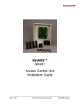
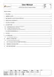
C-PRO NANO
PROGRAMMABLE CONTROLLERS
HARDWARE MANUAL
CODICE 114CPRNHWE03
C-PRO NANO HARDWARE MANUAL
Important
Please read these instructions carefully prior to installation and use, and follow all the precautions for installation and electrical
connections; keep these instructions with the device for future consultation.
The device must be disposed of in accordance with local regulations pertaining to the collection of electrical and electronic
appliances.
Page 2
C-PRO NANO HARDWARE MANUAL
Contents
1
INTRODUCTION ........................................................................................................................................ 4
2
COMPONENT AND AUXILIARY NETWORK SYSTEMS.................................................................. 5
3
TECHNICAL CHARACTERISTICS ........................................................................................................ 6
3.1
3.2
3.3
3.4
3.5
3.6
CONNECTIONS ......................................................................................................................................... 6
THE C-PRO NANO WIRING LAYOUT ...................................................................................................... 8
C-PRO NANO DIMENSIONS/INSTALLATION ......................................................................................... 10
GENERAL CHARACTERISTICS ................................................................................................................. 11
TECHNICAL CHARACTERISTICS .............................................................................................................. 11
ELECTRICAL CHARACTERISTICS............................................................................................................. 12
4
THE C-PRO NANO USER INTERFACE ............................................................................................... 14
5
C-PRO EXP MICRO I/O EXPANSION UNITS..................................................................................... 16
5.1
5.2
6
THE C-PRO EXP MICRO WIRING LAYOUT .......................................................................................... 17
C-PRO EXP MICRO DIMENSIONS/INSTALLATION................................................................................ 19
ACCESSORIES.......................................................................................................................................... 19
6.1
USER TERMINALS .................................................................................................................................. 19
6.1.1
V LEDi dimensions and installation............................................................................................. 20
6.1.2
V WALL dimensions and installation ........................................................................................... 22
6.2
EVDFAN1 CUT-OFF SPEED REGULATOR ............................................................................................... 29
6.3
ACCESSORIES FOR SUPERVISION AND MONITORING ............................................................................... 31
6.3.1
Non-insulated TTL/RS485 interface ............................................................................................. 31
6.3.2
Insulated TTL/RS485 interface..................................................................................................... 31
6.4
PROGRAMMING ACCESSORIES ................................................................................................................ 33
6.4.1
EVKEY programming key............................................................................................................. 33
6.4.2
EVPROG programming kit........................................................................................................... 33
Page 3
C-PRO NANO HARDWARE MANUAL
1 Introduction
The C-PRO NANO family of programmable controllers is the ideal solution for refrigeration, ventilation and
air conditioning applications in low complexity situations. Both in terms of regulation operations and the user
interface, the controller software is fully programmable, in a simple and intuitive manner, thanks to the use of
the UNI-PRO development environment.
The C-PRO NANO is manufactured as a panel installation version.
Using the 6 relay outputs, it is possible to control various types of devices such as compressors, water
circulation pumps, defrosting elements, condensation or evaporation fans, cycle inversion valves, alarm
warning indicators etc. The control process makes use of NTC probes for monitoring temperature and
0/4-20 mA or 0-5V ratiometric transducers for monitoring pressure. There are two alternative versions
according to the kind of Bus used: CANBus version and IntraBus version.
The C-PRO NANO is also equipped with digital inputs for monitoring unit functions; and it is also possible to
connect until two I/O expansion units (IntraBus version) or the expansions of the C-PRO EXP-MICRO, C-PRO
EXP-KILO, C-PRO EXP-MEGA, C-PRO EXP-GIGA families to increase the I/O (CAN version).
All the parameters may be adjusted from the user interface, and it is possible to upload and download
configuration data by means of a programming key.
The display has four red-coloured digits (plus decimal points) and 16 icons of various colours; the keypad has 4
keys.
C-PRO NANO
Page 4
C-PRO NANO HARDWARE MANUAL
2
Component and auxiliary network systems
Page 5
C-PRO NANO HARDWARE MANUAL
3 Technical characteristics
3.1 Connections
Power supply:
The C-PRO NANO is powered by a 12 V AC supply. It may also be powered by a 12 V DC supply; in this
case, there is no option for controlling the fan cut-off modules. The maximum length of the power supply
connecting cables is 1 m.
Analogue input connections:
The C-PRO NANO has two analogue inputs for NTC probes and two for NTC probes or for 0/4-20 mA or 0-5V
ratiometric transducers. Selection is made by the UNI-PRO development system. The current transducers may
be supplied by means of the 12 V DC terminal (refer to the physical layout) with a non-stabilised voltage equal
to 12 V DC. The maximum length of the analogue input connecting cables is 3 m.
Digital input connections:
The C-PRO NANO has 5 non-optoisolated digital inputs (clean contact). The maximum length of the digital
input connecting cables is 3 m.
Digital output connections:
The C-PRO NANO has up to 6 electromechanical relay digital outputs. The maximum length of the digital
output connecting cables is 3 m.
Analogue output connections:
The C-PRO NANO has 1 pulse modulation analogue output to drive the cut phase modules. The maximum
length of this analogue output connecting cables is 1 m.
The C-PRO NANO has 2 voltage or current (optional) analogue outputs. The maximum length of these
analogue outputs connecting cables is 3 m.
Remote terminal connections (IntraBus):
The connection between the C-PRO NANO and the terminal is made using a 3 way cable. The maximum
length of the terminal connection cables is 1 m if using a DC supply from the controller; 30 m where the wallmounted keypad is supplied using a separate transformer.
Remote expansions connection (IntraBus):
The connection between the C-PRO NANO and the I/O expansion units is made using a 3 way cable. The
maximum length of the remote I/O expansion units connecting cables is 1 m.
User interface connections (CAN):
The connection between C-PRO NANO and the remote user interface is made using a 2 way cable (better if it
is two weaved couples) plus possible ground.
The maximum length of the connection cables to the remote user interface depends of the CAN port baud rate .
-
1.000 m with 20.000 baud
500 m with 50.000 baud
250 m with 125.000 baud
50 m with 500.000 baud.
The CAN port baud rate is settable by parameter.
Page 6
C-PRO NANO HARDWARE MANUAL
Connection with a remote expansion (or an other CAN controller) :
The connection between C-PRO NANO and the remote expansion (or other CAN controller) is made using a 2
way cable (better if weaved) plus possible ground.
The maximum length of the connection cables to the remote controllers or expansions depend on the CAN port
baud rate (see above section “User interface connections”)
C-PRO NANO and the expansion ( or other CAN controller) power supplies has to be electrically
insulated one from the other.
Notes on the electrical connections
-
do not use electric or pneumatic screw-wrenches on the terminal board
if the device has been moved from a cold to a warm environment, condensation may have formed
inside; please wait approx. one hour prior to switching on
ensure that the voltage, frequency and operational power of the device are compatible with the local
power supply
disconnect the power prior to proceeding with any kind of maintenance operation
do not use the device as a safety device
for repairs and any information relating to the device, contact the Evco dealer network.
Caution
The instructions governing maximum connecting cable lengths imply that a range of precautions are being
observed:
In order to avoid exemption problems, it is good practice to comply with the following instructions:
- Avoid locations with antennae
- Avoid cabling probe inputs and relay outputs together; generally avoid mixing low and high voltage
signals
- Avoid wrapping cabling around power components
In order to avoid safety problems, it is good practice to comply with the following instructions:
- Avoid premises with relative humidity >90%
- Avoid water
- Avoid corrosive environments
- Avoid explosive environments
Special recommendations
Finally, ensure that the operating conditions are within the limits of use described in the technical
characteristics.
Page 7
C-PRO NANO HARDWARE MANUAL
3.2 The C-PRO NANO wiring layout
The C-PRO NANO control unit wiring layout is shown below, with the meanings of the inputs and outputs
given in the tables.
C-PRO NANO wiring diagram
Connector 1: Output relay connection
Conn.
Abbrev.
Description
C1-1 DO4
Relay No.4, breaker normally open
C1-2 DO3
Relay No.3, breaker normally open
C1-3 COMMON1
Relays No.s 1,2,3,4 - common
C1-4 DO5
Relay No.5, breaker normally open
C1-5 DO2
Relay No.2, breaker normally open
C1-6 DO1
Relay No.1, breaker normally open
C1-7 COMMON1
Relays No.s 1,2,3,4 - common
C1-8 COMMON1
Relays No.s 1,2,3,4 - common
C1-9 COMMON DO5
Relay No.5 - common
C1-10
Not used
C1-11 DO6
Relay No.6, breaker normally open
Connector 2: Connection for the parameter upload/download key and/or output for RS485 module
and/or controller flash download module
Page 8
C-PRO NANO HARDWARE MANUAL
Connector 3: Analogue output connector
Conn.
Abbrev.
Description (V+I version)
C3-1 AO2
0-10 V DC
C3-2 GND
Common analogue output
C3-3 AO3
4-20 mA
Description (I+I version)
C3-1 AO2
4-20 mA
C3-2 GND
Common analogue output
C3-3 AO3
4-20 mA
Description (V+V version)
C3-1 AO2
0-10 V DC
C3-2 GND
Common analogue output
C3-3 AO3
0-10 V DC
Connector 4: Connector for low voltage signals
Conn.
Abbrev.
Description
C4-1 12 V AC (Power)
Device power supply (12 V AC/DC)
C4-2 5V
Ratiometric power supply
C4-3 GND
Common analogue and digital inputs
C4-4 GND
Common analogue and digital inputs
C4-5 AI4
Analogue input No. 4 (for NTC probes or for 0/4-20 mA or 0-5V
transducers)
C4-6 AI3
Analogue input No. 3 (for NTC probes or for 0/4-20 mA or 0-5V
transducers)
C4-7 AI2
Analogue input No. 2 (for NTC probes)
C4-8 AI1
Analogue input No. 1 (for NTC probes)
C4-9 12 V AC (Power)
Device power supply (12 V AC/DC)
C4-10 12 V DC
Current transducer and cut-off module power supply (50 mA max.
not protected against short circuits)
C4-11 AO1
Cut-off module impulse output
C4-12 DI5
Digital input No. 5
C4-13 DI4
Digital input No. 4
C4-14 DI3
Digital input No. 3
C4-15 DI2
Digital input No. 2
C4-16 DI1
Digital input No. 1
Connector 5: Connector for remote keypad and I/O expansion unitb(IntraBus)
Conn.
Abbrev.
Description
C5-1 12 V DC
Remote keypad power supply (12 V DC 50 mA max.; not protected
against short circuits)
(Please note: any expansion units must have a local power supply)
C5-2 GND
Common
C5-3 DATA
Powered serial connection
Connector 5: Connector for remote keypad and I/O expansion unit (CAN)
Conn.
Abbrev.
Description
C5-1 CAN+
Connector for the serial CAN+ connection
C5-2 GND
Ground reference connection
C5-3 CANConnector for the serial CAN- Connection
Page 9
C-PRO NANO HARDWARE MANUAL
3.3 C-PRO NANO dimensions/installation
The mechanical dimensions for the C-PRO NANO are given below; the measurements are in mm (in).
For fitting, use the snap-on brackets provided.
Dimension
A
B
Minimum
71.0 (2.795)
29.0 (1.141)
Typical
71.0 (2.795)
29.0 (1.141)
Maximum
71.8 (2.826)
29.8 (1.173)
Recommendations for installation:
- the panel thickness must not exceed 8 mm (0.314 in)
- 95.0 (3.740) is the maximum depth with casing 0065300060 correctly inserted (the connector is not
supplied with the device)
- ensure that the operating conditions (operating temperature, humidity, etc.) are within the limits
indicated in the technical data sheets
- do not install the device near to any sources of heat (heating elements, hot air conduits, etc.),
equipment containing powerful magnets (large diffusers, etc.), areas affected by direct sunlight, rain,
humidity, excessive dust, mechanical vibration or shock
- in compliance with safety regulations, the device must be installed correctly, and in such a way as to
protect against any contact with electrical parts; all safety devices must be fixed so that they cannot be
removed without the use of tools.
Page 10
C-PRO NANO HARDWARE MANUAL
3.4 General characteristics
Safety reference standards
Scope of the device
EN60730-1
A programmable electronic controller for
refrigeration, ventilation and air
conditioning applications
-10T70°C Non-condensing RU<80%
0T50°C Non-condensing RU<80%
Add-on control device; assumes the
classification of the equipment into
which it is integrated
Reduced interruption (relay breakers)
>=250 V
Panel mounted
1C
Normal
A
Long
IP65
Storage conditions
Operational conditions
Electric shock protection class
Disconnection type
PTI of the insulation materials
Case
Action type
Pollution
Software class
Insulated parts electrical stress period
Front panel protection classification
3.5 Technical characteristics
Low voltage signal connections
Power connector
Connection for connecting the EVCO powered serial
port to the remote keypad and/or remote I/O expansion
card
Connection for parameter key, TTL serial output for
RS485 module, Flash programming interface
Connection for D/A output
16 way Mini-Fit
12 way Inarca Edge connector
Cable diameter > 0.75 mm2; as
altenative, 12 way Sauro Edge connector
JST 3 way P2.5
6 way AMP micro-match
JST 3 way P2.5
16 WAY MINI-FIT CONNECTOR SPECIFICATIONS
SUPPLIER
CONNECTOR CODE
CONTACT CODE
CP-01 1000102 (AWG16÷24)
SELECOM
CP-01 116010 (V2)
CP-01 116020 (V0)
6137R16WO (V2)
JUSCOM
1090-557-162 (V2)
Please note:
use the special tool for crimping
CVILUX
CONEXCON
MOLEX
6740-1161 (V2)
6740-1160 (V0)
39-01-2160 (V2)
39-01-2165 (V0)
Page 11
6137TR1 (AWG16÷20)
6137TR2 (AWG22÷26)
1150-156-012 (AWG18÷22)
1150-156-002 (AWG22÷26)
6744-2000 (AWG18÷22)
39-00-0038 (AWG18÷24)
39-00-0046 (AWG22÷28)
C-PRO NANO HARDWARE MANUAL
3.6 Electrical characteristics
CPU
Power supply
Digital outputs
Digital inputs
Analogue inputs for
NTC probes
Analogue inputs for
NTC probes or
Ratiometric pressure
Transducers
Microcontroller
Program flash memory
RAM for data memory
EEPROM
A/D
Voltage
Range
Frequency
Maximum input power
Fuse rating
Number
Type
Maximum breaker current at 250 V AC
Use all common connectors.
Number of processing cycles
Minimum switching interval
Micro-switch action type
Insulation between relays and low
voltage
Insulation between relays
Insulation between relays and DO6
Number
Type
Breaker closure current to earth
Maximum closure resistance
OFF to ON detection time
ON to OFF detection time
Number
Type
NTC measurement range
NTC measurement accuracy
NTC measurement sensitivity
Number
Type
NTC measurement range
NTC measurement accuracy
NTC measurement sensitivity
Type
Current measurement range
Current measurement accuracy
Current measurement sensitivity
Input resistance
Type
Voltage measurement range
Voltage measurements accuracy
Voltage measurement sensitivity
Page 12
8 bit
128 Kbyte
4 Kbyte
4 Kbyte
8 channels at 10 bit
12 V AC/DC
-10% +15%
50/60 Hz / DC
6 VA
External
6
Electromechanical relays
2 (1) A for DO1, DO2, DO3
and DO4
3 (1) A for DO5 and DO6
100,000
20 s
1C
Reinforced
Functional
Reinforced
5
Clean contact
2 mA
100 Ω
100 ms
100 ms
2
NTC (10 KΩ ±1% @25°C)
-40°C ÷ 100°C
±1°C
0.1°C
2
NTC (10 KΩ ±1% @25°C)
-40°C ÷ 100°C
±1°C
0.1°C
Current
0/4 ÷ 20 mA
±0.08 mA
0.01 mA
200 Ohm
Ratiometric
0 ÷ 5V
±50 mV
10 mV
C-PRO NANO HARDWARE MANUAL
Fan analogue output
UART1 TTL
for RS485 serial port
(Modbus)
Serial output for remote
I/O expansion unit
and remote keypad
Analogue output
Voltage + Current,
Voltage + Voltage or
Current + Current
CAN communication
Bus
Number
Type
Number
Type
Physical layer
Maximum baud rate
Connector
Please note: The same connector for
the serial port is used for the
parameter key and for the interface
used for programming the
microcontroller flash memory
Number
Type
Physical layer
Baud rate
Connector
Number
Connector
Power supply
Type
Current range
Current output accuracy
Current output sensitivity
Current output load
Adjustment time
Type
Voltage range
Voltage output accuracy
Voltage output sensitivity
Output impedance
Adjustment time
Number
type
Physical layer
Baud rate (max. length
Baud rate (max. length
Baud rate (max. length
Baud rate (max. length
Connector
= 1000 m)
= 500 m)
= 250 m)
= 50 m)
1
EVCO impulse cut-off
1
UART
TTL level signals
19200 bit/s
6 way AMP micro-match
1
EVCO powered serial port
12 V DC, GND, DATA
19200 bit/s
sconn. JST 3 way P2.5
1+1
sconn. JST 3 way P2.5
Internal (non optoisolated)
Current
4 ÷ 20 mA
±0.4 mA
0.01 mA
47 ÷ 300 Ω
1s
Voltage
0 ÷ 10 V
±200 mV (unloaded)
10 mV
100 Ω
1s
1
CAN V2.0B no optoinsulated
2 wires + common wire
(ISO 11898)
20K
50K
125K
500K
Disconnectable screw terminals
Note:
1) baud rate selectable by parameters
2) The CAN connection consists of a cable with twisted pair (both shielded and
not shielded). The first and the last elements of the system must have the bus
terminating resistor connected (impedance is 120Ω).
Page 13
C-PRO NANO HARDWARE MANUAL
4 The C-PRO NANO user interface
The display has four red-coloured digits (plus decimal points) and 16 icons of various colours; the keypad has 4
keys.
C-PRO NANO
Display
Number of digits
Colour
Summer icon (air conditioning display)
Circuit 1 icon (refrigeration display)
Winter icon (air conditioning display)
Circuit 2 icon (refrigeration display)
Fan icon (air conditioning display)
High pressure circuit icon (refrigeration display)
Pump icon (air conditioning display)
Low pressure circuit icon (refrigeration display)
EVCO icon
Defrost icon (air conditioning display)
Fan icon (refrigeration display)
°F icon (air conditioning display)
Bar icon (refrigeration display)
°C icon
4
Red
Colour
Green
Colour
Green
Colour
Green
Colour
Green
Colour
Colour
Amber
Amber
Colour
Red
Colour
Red
Page 14
C-PRO NANO HARDWARE MANUAL
Maintenance icon
Alarm icon
Icon 1
Icon 2
Icon 3
Icon 4
Heating element icon (air conditioning display)
Compressor icon (refrigeration display)
On-Off icon
Keys
Set / enter key
Number of keys
Normal pressing
OnOff/esc key
Pressed for approx. 3
seconds
Normal pressing
Up key
Down key
Esc+enter keys
Up+down key
Pressed for approx. 3
seconds
Normal pressing
Secondary function
Normal pressing
Secondary function
Pressed for approx. 3
seconds
Pressed for approx. 3
seconds
Colour
Colour
Colour
Colour
Colour
Colour
Colour
Red
Red
Green
Green
Green
Green
Green
Colour
Red
4
ENTER (confirms the value/runs the
command)
Accesses programming parameters
ESC (cancels the value/returns to the
previous menu)
Powers the unit on/off
UP
Programmable
DOWN
Programmable
Accesses the second level programming
parameters
Displays device/firmware version, revision
information
Page 15
C-PRO NANO HARDWARE MANUAL
5
C-PRO EXP MICRO I/O expansion units
The C-PRO EXP MICRO I/O expansion units allow expansion of the controllers I/O capacity. There are two
types of expansion unit, one sealed in a case with 4 DIN modules, and another open mounted on a base with 4
DIN modules.
C-PRO EXP MICRO
Sealed case version with 4 DIN
modules
C-PRO EXP MICRO
Open version mounted on a base
with 4 DIN modules
Page 16
C-PRO NANO HARDWARE MANUAL
5.1 The C-PRO EXP MICRO wiring layout (IntraBus version)
The references to connecting cable lengths reported in chapter 3 are also valid for I/O expansion units.
The C-PRO EXP MICRO expansion unit wiring layout is shown below, with the meanings of the inputs and
outputs given in the tables.
C-PRO EXP MICRO wiring diagram
The C-PRO NANO and C-PRO EXP MICRO power supplies must be galvanically isolated
from one another.
Connector 1: Output relay connection
Conn.
Abbrev.
Description
C1-1 DO1
Relay No.1, breaker normally open
C1-2 COMMON DO1
Relay No.1 - common
C1-3 DO2
Relay No.2, breaker normally open
C1-4 COMMON DO2
Relay No.2 – common
C1-5 DO3
Relay No.3, breaker normally open
C1-6 COMMON DO3
Relay No.3 - common
C1-7 DO4
Relay No.4, breaker normally open
C1-8 COMMON DO4, DO5 Relay No.s 4, 5 - common
C1-9 DO5
Relay No.5, breaker normally open
C1-11 DO6
Relay No.6, breaker normally open
Page 17
C-PRO NANO HARDWARE MANUAL
C1-12
COMMON DO6
Relay No.6 - common
Connector 2: Connector for low voltage signals
Conn.
Abbrev.
Description
C2-1 12 V AC (Power)
Device power supply (12 V AC/DC)
C2-2 Not connected
Not connected
C2-3 GND
Common analogue and digital inputs
C2-4 GND
Common analogue and digital inputs
C2-5 AI4
Analogue input No. 4 (for NTC probes or for 0/4-20 mA or 0-5V
transducers)
C2-6 AI3
Analogue input No. 3 (for NTC probes or for 0/4-20 mA or 0-5V
transducers)
C2-7 AI2
Analogue input No. 2 (for NTC probes)
C2-8 AI1
Analogue input No. 1 (for NTC probes)
C2-9 12 V AC (Power)
Device power supply (12 V AC/DC)
C2-10 12 V DC
Current transducer and cut-off module power supply (50 mA max.
not protected against short circuits)
C2-11 AO1
Cut-off module impulse output
C2-12 DI5
Digital input No. 5
C2-13 DI4
Digital input No. 4
C2-14 DI3
Digital input No. 3
C2-15 DI2
Digital input No. 2
C2-16 DI1
Digital input No. 1
Connector 3: Connector to the controller (IntraBus)
Conn.
Abbrev.
Description
C3-1 VDC
Power supply
C3-2 GND
Common
C3-3 DATA
Powered serial connection
Connector 3: Connector to the controller (CAN)
Conn.
Abbrev.
Description
C3-1 +
Connector for the serial CAN + connection
C3-2 GND
Ground reference connector
C3-3 Connector for the serial CAN - connection
Page 18
C-PRO NANO HARDWARE MANUAL
5.2 C-PRO EXP MICRO dimensions/installation
The mechanical dimensions for the C-PRO EXP MICRO are given below; the measurements are in mm (in).
6
Accessories
6.1 User terminals (IntraBus)
User terminals allow the control units to be controlled remotely (display and commands). There are two
interface types, one panel-mounted, the other wall-mounted. The interface is connected to the special (powered)
serial connector of the C-PRO NANO controllers.
V LEDi
V WALL
Panel-mounted version
Wall-mounted version
Page 19
C-PRO NANO HARDWARE MANUAL
6.1.1
V LEDi dimensions and installation
For panel installation, use the snap-on brackets provided
Local panel interface dimensions
Connections
3 2 1
GND
12Vdc
DATA
CI1
Local panel interface connections
Connector CI1: Interface connector
Conn.
Abbrev.
Description
CI1-1 12 V DC
Keypad power supply
CI1-2 GND
Common
CI1-3 DATA
EVCO powered serial port
C-PRO NANO with V LEDi wiring diagram
Page 20
C-PRO NANO HARDWARE MANUAL
The user interface has a 7 segment, 4 digit display (plus decimal point), 6 icons, and the user mode is achieved
using 4 keys.
Display
Number of digits
Colour
4
Red
Summer icon
Winter icon
Compressor icon
Pump icon
Defrost icon
Alarm icon
Colour
Colour
Colour
Colour
Colour
Colour
Red
Red
Red
Red
Red
Red
Keys
Set / enter key
Number of keys
Normal pressing
On-Off/esc key
Pressed for approx. 3
seconds
Normal pressing
4
ENTER (confirms the value/runs the
command)
Accesses programming parameters
Up key
Down key
Esc+enter keys
Up+down key
Pressed for approx. 3
seconds
Normal pressing
Secondary function
Normal pressing
Secondary function
Pressed for approx. 3
seconds
Pressed for approx. 3
seconds
ESC (cancels the value/returns to the
previous menu)
Powers the unit on/off
UP
Programmable
DOWN
Programmable
Accesses the second level programming
parameters
Displays device/firmware version, revision
information
Page 21
C-PRO NANO HARDWARE MANUAL
6.1.2
V WALL dimensions and installation
For wall installation, use appropriate rawplugs and screws.
Wall-mounted version - dimensions
GND
12Vac
DATA
12Vac
Connections
1 2 3 4
CI2
Wall-mounted version wiring diagram
Page 22
C-PRO NANO HARDWARE MANUAL
Connector CI2: Terminal connector powered by a separate transformer
Conn.
Abbrev.
Description
CI2-1 12 V AC
Remote interface AC power supply
CI2-2 12 V AC
Remote interface AC power supply
CI2-3 DATA
EVCO powered serial connection
CI2-4 GND
Common
C-PRO NANO with V WALL wiring diagram (terminal powered by a separate 12 V AC
transformer; the maximum length of the terminal power cables is 1 m, the maximum length of
cables connecting the C-PRO NANO and V WALL is 30 m)
Make the C-PRO NANO – V WALL connection using a twisted-pair cable; ensure that the cable does not run
along side any high voltage sections.
Connector CI2: Terminal connector, powered by the C-PRO NANO
Conn.
Abbrev.
Description
CI2-1 12 V DC
Keypad DC power supply
CI2-2 GND
Common
CI2-3 DATA
EVCO powered serial connection
CI2-4 GND
Common
C-PRO NANO with V WALL wiring diagram (terminal powered by C-PRO NANO; the maximum
length of the connecting cables is 1 m)
Page 23
C-PRO NANO HARDWARE MANUAL
The user interface has a 7 segment, 4 digit display (plus decimal point), 6 icons and the user mode is achieved
using 4 keys.
Display
Number of digits
Colour
4
Red
Led L0
Led L1
Led L2
Led L3
Led L4
Led L5
Colour
Colour
Colour
Colour
Colour
Colour
Red
Red
Red
Red
Red
Red
Keys
Set / enter key
Number of keys
Normal pressing
On-Off/esc key
Pressed for approx. 3
seconds
Normal pressing
4
ENTER (confirms the value/runs the
command)
Accesses programming parameters
Up key
Down key
Esc+enter keys
Up+down key
Pressed for approx. 3
seconds
Normal pressing
Secondary function
Normal pressing
Secondary function
Pressed for approx. 3
seconds
Pressed for approx. 3
seconds
ESC (cancels the value/returns to the
previous menu)
Powers the unit on/off
UP
Programmable
DOWN
Programmable
Accesses the second level programming
parameters
Displays device/firmware version, revision
information
Page 24
C-PRO NANO HARDWARE MANUAL
6.2 Remote User interface (CAN)
The user interfaces allow to install a display and keyboard remotely far from the controller .
“V-VIEW” user interface (with a alfanumeric 4 x 20 characters LCD display) can be connected to the CAN
port of the C-PRO NANO controller. On request a graphic 240 x 128 pixel LCD display (V-GRAPH) user
interface is also available .
6.2.1
V-VIEW
The visualized text on the LCD display, the LEDs and key functions of the user interface are realized with
UNI-PRO software development system and use a “browser” technology to load the C-PRO MICRO pages and
to refresh the visualized variable value. The user interface is directly interfaced with the controller without
downloading any software.
The typical implemental functionality are :
•
intuitive navigation with “ browser style”
•
text and icon combination
•
tables utilization with “scroll” possibilities.
6.2.1.1 V-VIEW User Interface
V-VIEW
Page 25
C-PRO NANO HARDWARE MANUAL
The following table summarizes the keyboard button meaning:
BUTTONS
MAIN FUNCTION
SECONDARY FUNCTION
Predefined as UP
Predefined as DOWN
Predefined as LEFT
Predefined as RIGHT
Predefined as ESC
Stand-By command
Predefined as ENTER
1° programming level command
Programmable
Alarm reset / identification
Programmable
Programmable
Programmable
Programmable
Programmable
+
+
+
Controller configuration parameters
command
2° programming level command
3° programming level command
The following table summarizes the meaning of the LEDs on front panel :
LED
LM
LS
LP
L0
L1
L2
L3
L4
L5
Page 26
FUNCTION
Predefined (blinking during the
parameters configuration of the
controller)
Programmable
Programmable
Programmable
Programmable
Programmable
Programmable
Programmable
Programmable
C-PRO NANO HARDWARE MANUAL
6.2.1.2 V-VIEW wiring layout
6.2.1.3 V-VIEW specifications
General specifications
Safety standards references
EN 60730-1
Purpose of the device
Electronic control device connections
To be integrated in equipment
Plug-in terminal block 5mm pitch
for conductors up to 2.5 mm2
-20T70 °C (@RH<90% non-condensing)
-10T60 °C
0T50 °C for version with integrated LCD
(@RH<90% non-condensing)
An integrated control device takes up the
classification of the equipment which it is
integrated with
>250
Storage temperature limits
Ambuent temperature limits
Electrical shock protection classification
PTI of insulation materials used
Housing
Installation
Housing
Electrical specifications
Power supply
CPU
EEPROM
Pannel mounting
160 x 160 mm
Main (input)
Microprocessor
Oscillator frequency
Memory for parameters
Number
12Vdc, 0.2A
16 bit
16 MHz
256 byte
1
Page 27
C-PRO NANO HARDWARE MANUAL
Type
Serial CAN Communication
Buzzer
LCD Dispay
Keyboard
CAN V2.0B
not optoisolated
2 wires + common, ISO 11898 standard
20K
50K
125K
500K
Sconnectable terminals
Physical Layer
Baud rate (L max. = 10 m)
Baud rate (L max. = 5 m)
Baud rate (L max. = 2 m)
Baud rate (L max. = 1 m)
Connector
Note: baud rate can be selected by parameter
Note: The physical level of the CAN consists of a cable with twisted pair (both shielded
and not shielded). The terminator's impedance is 120Ω. A second cable with twisted
pairis used for feeding and common (ground)
Number
1
4 x 20 alfanumeric backlight
1
Buttons
12
Led
9
Page 28
C-PRO NANO HARDWARE MANUAL
6.3 EVDFAN1 cut-off speed regulator
The EVDFAN1 is a cut-off speed regulator for controlling single-phase fans (fans with maximum current
absorption equal to 5 A).
It is ideal for controlling the condensation/evaporation fans on a refrigeration control unit.
EVDFAN1
The fan module is available as an open card version, and is mounted on a plastic base suitable for fitting on a
DIN rail.
135 mm x 71 mm
DIN rail fan module dimensions
Connections
C-PRO NANO with EVDFAN1 wiring diagram
Page 29
C-PRO NANO HARDWARE MANUAL
Terminals 1 and 2: Control input connector (Phoenix pull-out)
Conn.
Abbrev.
Description
1
12 V DC
12 V DC power supply
2
AO1
Impulse cut-off input
Terminals 3, 4, 5 and 6: Power connectors (FAST-ON)
Conn.
Abbrev.
3
LOAD
Load
4
LOAD
Load (Neutral)
5
LOAD
Neutral 230 V AC
6
LOAD
Live 230 V AC
Description
The cut-off module allows the control of single-phase fans with a maximum current equal to 5 A. The fan
module live feed must be the same as that feeding the controller.
If the C-PRO NANO has a DC power supply, then it is not possible to control the fans using the EVDFAN1.
Example:
V AC = 230 V
I max = 5 A
VA (max) = 230*5 = 1150 VA
W (max) = 230*5*cosφ = 1150 Watts if cosφ=1
Page 30
C-PRO NANO HARDWARE MANUAL
6.4 Accessories for supervision and monitoring
These modules allow the conversion of TTL signals to RS485 signals (with or without isolation) for supervision
using the MODBUS protocol.
The modules connect to the special 6 way AMP micro-match connector on the controller; this connector is
shared with the parameter programming key and with the controller flash memory programming tools.
6.4.1
Non-insulated TTL/RS485 interface
EVIF20TSX
6.4.2
Insulated TTL/RS485 interface
EVIF21TS7I dimensions/installation
EVIF21TS7I
Dimensions/Installation on DIN rail
Page 31
C-PRO NANO HARDWARE MANUAL
EVIF21TS7I connections
Insulated interface wiring diagram
Connector
Conn.
Abbrev.
11
+
13
15
shield
75
Power supply
77
Power supply
Description
RS485+
RS485COMMON
230 V AC
230 V AC
Page 32
C-PRO NANO HARDWARE MANUAL
6.5 Programming accessories
6.5.1
EVKEY programming key
The EVKEY programming key allows
downloading/uploading parameters
(even when the controller is not powered; in this
case it is necessary to use the EVPS power
supply).
The key is connected to the special 6 way AMP
micro-match connector, also used for
supervision.
EVKEY
6.5.2
EVPROG programming kit
The EVPROG programming kit allows downloading programs into the flash memory of the C-PRO NANO
controller (even when the controller is not powered; in this case, it is necessary to use the EVPS power supply).
The EVPROG is connected to the special 6 way AMP micro-match connector, also used for the parameter
programming key or for supervision.
The kit is comprised of the following components:
1.
The EVIF20TRX interface.
2.
Pony Prog (9 pin – RJ 11) tray adapter.
3.
ECCC506 telephone cable.
Preparation of the EVPROG kit hardware:
5
Connect the Pony Prog tray adapter to the
computer serial port. Connect the EVIF20TRX
interface to the controller AMP micro-match
connecter. Connect one end of the ECCC506
telephone cable to the Pony Prog tray adapter,
and the other end to the EVIF20TRX interface.
9
4
8
3
7
A B CDEF
2
6
1
RJ11 / DB-9
EVPROG
Page 33
Micro-Match / RJ11
C-PRO NANO HARDWARE MANUAL
7 CAN Connection
C-PRO NANO can be connected to other controllers, to expansion modules and to one or more user interfaces
using either local or wide CAN serial port. The CAN bus uses the ISO 11898 standard, a balanced two-wire
communication very similar to the RS 485 standard.
Resistors with a recommended rating of 120-124 ohm have to be fitted at each end of the bus.
CAN
NODE
(C-PRO
NANO)
CAN
NODE
(V-VIEW)
CAN+
120ohm
120ohm
CANCAN
NODE
(C-PRO EXP
MICRO)
If connection is established through the Local CAN bus, it is possible to power a user interface using the 4terminal connector, according to the following table:
C-PRO NANO
C3-1 (CAN+)
C3-3 (CAN-)
C3-2 (GND )
V-VIEW User Interface
PA 1 (VCD) needs independent power supply
PA 2 (CAN+)
PA 3 (CAN-)
PA 4 (GND )
The maximum number of expansions and user terminals is 32.
The maximum number of controllers for the user terminal V-VIEW is 2.
Page 34
C-PRO NANO HARDWARE MANUAL
7.1 Notes on the parameter of the controller relative to the CAN net
configuration
To log on the controller parameters configuration procedure relative to the analogic output act in the following
way :
Both for the remote or built-in user interface :
1.
Ensure that the controller and the user interface are both switched on and no utilization is connected
with the analogic output
2.
and
buttons for two seconds : the first available voice
Keep pressed at the same time
will be visualized (the voices are relative to the controller; for the voices relative to the user
interface repeat the selection from “reset”).
To select the controller parameters relative to the CAN network configuration:
1.
Press and release
button to select “CAN” voice.
2.
Press and release
button: if the controller is visualizing the net parameters, the voice “Input
Password” will be visualized: in this case see the following 3. and 4. (in opposite case see directly point 5.).
3.
Press and release
button: the cursor blinking.
4.
Press and release
button to set “ -19”.
5.
Press and release
button: the first voice available will be visualized.
To select a parameter:
1.
Press and release
button
To modify a parameter:
1.
Press and release
button: the cursor blinking.
2.
Press and release
or
3.
Press and release
button to confirm the selection done.
4.
Switch – off the controller.
buttons to select the value
For a quick closing procedure :
1.
Press and release repeatedly
button
Page 35
C-PRO NANO HARDWARE MANUAL
The main parameters of the CAN net are the following :
•
•
•
•
“My Node” (represents the data sender ID )
“Network Node” (represents the receiver ID)
Baud rate (represent the data transmissions speed; initially it can be useful to let this value
set at “Auto”; in this way the device will try to connect a few time with different speed)
Master (represents network operation) when instrument is set as master it checks device network to find
Devices presence. A controller with I/O expansions needs to have MASTER = TRUE.
Predefined value :
•
•
•
the parameter My Node for a controller is set at 1
the parameter My Node for an expansion is set at 2
the parameter My Node for a user interface is set at 99.
Every device in the network represents a knot (the maximum knot numbers are 32); each knot has an ID (the Id
range is from 1 to 127).
Every device in the network has to be set as regards the network components through “Network Node”
parameters.
Example:
If a controller, an expansion and a user interface are installed, set the following value on the controller in the
following way :
1.
Assign at “Network Node 1” the address “2” (expansion).
2.
Assign at “Network Node 2” the address “99” (user interface).
Repeat the same operations for the expansion and the user interface.
ATTENTION: the parameters as regards the net could be overwritten by the application software.
Page 36
C-PRO NANO HARDWARE MANUAL
C-PRO NANO hardware manual.
Version 1.03 January 2009.
CODE 114CPRNHWE03.
File 114CPRNHWE03.pdf.
This document is the exclusive property of Evco, whereby any reproduction or distribution is strictly forbidden, unless expressly directly authorised by Evco. Evco
assume no responsibility in relation to the characteristics, technical data and any possible errors reported in this document or deriving from the use of the same. Evco
cannot be held responsible for any damage caused by failure to observe these warnings. Evco reserves the right to make modifications of any kind and without prior
warning without prejudicing the essential operational and safety characteristics.
Page 37
HEAD OFFICE
Evco
Via Mezzaterra 6, 32036 Sedico Belluno ITALY
Tel: 0437-852468
Fax: 0437-83648
[email protected]
www.evco.it
OVERSEAS OFFICES
Control France
155 Rue Roger Salengro, 92370 Chaville Paris FRANCE
Tel: 0033-1-41159740
Fax: 0033-1-41159739
[email protected]
Evco Latina
Larrea, 390 San Isidoro, 1609 Buenos Aires ARGENTINA
Tel: 0054-11-47351031
Tel: 0054-11-47351031
[email protected]
Evco Pacific
59 Premier Drive Campbellfield, 3061, Victoria Melbourne, AUSTRALIA
Tel: 0061-3-9357-0788
Fax: 0061-3-9357-7638
[email protected]
Evco Russia
111141 Russia Moscow 2-oy Proezd Perova Polya 9
Tel: 007-495-3055884
Fax: 007-495-3055884
[email protected]
Every Control do Brasil
Rua Marino Félix 256, 02515-030 Casa Verde São Paulo SÃO PAULO BRAZIL
Tel: 0055-11-38588732
Fax: 0055-11-39659890
[email protected]
Every Control Norden
Cementvägen 8, 136 50 Haninge SWEDEN
Tel: 0046-8-940470
Fax: 0046-8-6053148
[email protected]
Every Control Shanghai
B 302, Yinhai Building, 250 Cao Xi Road, 200235 Shanghai CHINA
Tel: 0086-21-64824650
Fax: 0086-21-64824649
[email protected]
Every Control United Kingdom
Unit 19, Monument Business Park, OX44 7RW Chalgrowe, Oxford, UNITED KINGDOM
Tel: 0044-1865-400514
Fax: 0044-1865-400419
[email protected]