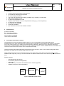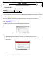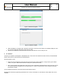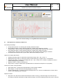
1
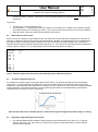
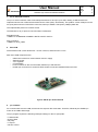
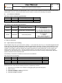
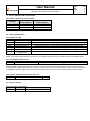
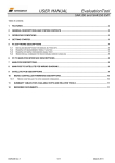
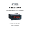
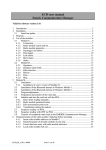
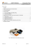
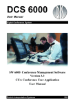
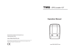
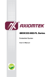
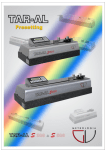
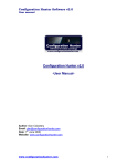
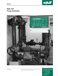
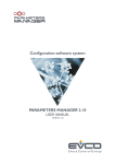
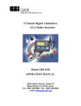
User Manual DOK Rev. Page of SAR100 Gyro Sensor Evaluation Platform 306 0 1 9 Table of contents: 1 FEATURES ............................................................................................................................................................................... 2 2 ABBREVIATIONS ................................................................................................................................................................... 2 3 DESCRIPTION AND SYSTEM CONTENTS ....................................................................................................................... 2 4 OPERATING CONDITIONS .................................................................................................................................................. 3 5 GETTING STARTED .............................................................................................................................................................. 3 6 PC SOFTWARE ........................................................................................................................................................................ 4 6.1 6.2 6.3 6.4 DESCRIPTIONS FOR ALL MENUS, BUTTONS ETC. .................................................................................................................... 5 MEASUREMENT RESULT LOG FILE ........................................................................................................................................ 6 A SIMPLE INTEGRATED ANGLE TEST ..................................................................................................................................... 6 REGARDING SUPPORTED ANGULAR RATE RANGES ................................................................................................................ 6 7 PC TO EVP PCB INTERFACE .............................................................................................................................................. 7 8 EVP PCB .................................................................................................................................................................................... 7 9 µC FIRMWARE........................................................................................................................................................................ 7 9.1 10 10.1 µC TO SENSOR COMMANDS .................................................................................................................................................. 8 SPECIAL COMMANDS ...................................................................................................................................................... 8 GYRO SENSORS ERROR HANDLING........................................................................................................................................ 8 11 EVP TO SATELLITE PCB WIRING DIAGRAM ............................................................................................................ 9 12 ORDERING INFORMATION ............................................................................................................................................ 9 13 REVISION HISTORY .......................................................................................................................................................... 9 Date Sign Rev Reference Prepared 091215 ROW 0 Archive Checked 091215 AÅB 1 EM Approved 091215 HRP 2 EM 12536 Date Dok 091216 HKW Stamp User Manual SAR100 Gyro Sensor Evaluation Platform 1 306 0 2 9 Features 2 DOK Rev. Page of Angular rate and temperature measurements Up to 2000 Hz sampling rate supported On-screen data presentation Log to file and large data size handling capability (only limited by PC RAM size) Easy sensor interface access µC firmware upgradable via USB Satellite PCBs available for more comprehensive testing (e.g. over temperature) µC firmware code available PC software code available Schematics available Non-standard versions of PC software available Abbreviations µC: Micro Controller EVP: Evaluation Platform FTP: File Transfer Protocol PCB: Printed Circuit Board USB: Universal Serial Bus 3 Description and system contents The SAR100 Gyro Sensor Evaluation Platform (EVP) is a low cost evaluation tool providing rapid sensor measurements in an office desk environment. Sensor data is requested from PC software and results are presented on the PC screen. Menus in PC software are few and easily understood. Data log to file is supported. Numerous sensor pins are made available on header pin rows for monitoring purposes. Add-on satellite boards are available and can be connected to the EVP PCB for more comprehensive testing. The EVP PCBs can be shipped without any target sensors pre-mounted - which is the required configuration when planning to test SAR100 on a satellite PCB directly from start. NOTE: Make sure there is only one SAR100 sensor in the system at any time (either on the EVP PCB or on the satellite PCB if using this). Trying to communicate with two SAR100 sensors at the same time will give communication error. System contents: - User Manual (this document) PC software (Xp and Vista supported) USB cable EVP PCB with µC firmware and SAR100 sensor mounted (optional) Satellite PCB (to be ordered separately) Satellite PCB USB EVP PCB PC with EVP software Figure 1: SAR100 EVP system contents User Manual SAR100 Gyro Sensor Evaluation Platform 4 DOK Rev. Page of 306 0 3 9 Operating conditions Table 1: EVP PCB operating conditions Parameter Ambient temperature for EVP Specification Min Max Unit 10 30 °C Testing over temperature can be performed by connecting the EVP PCB to a satellite PCB. (See chapter 11 and 12 for more information.) 5 Getting started Make sure to obtain the current version of PC software from Sensonor Technologies. This can be done by downloading the current installation package directly from the FTP server, or by addressing a request to our support address ([email protected]). The FTP server details: FTP address: ftp://195.1.76.74 (copy and paste this address into a web browser) User name: sen Password: sen Figure 2: FTP server login Software and driver installation: 1. Copy the software installation package to a local folder, e.g. „C:\work\EVP', and run setup.exe 2. A pop-up message during installation will ask for permission to install a USB driver (6119.inf) for the EVP. Click “Install the driver software anyway”. Verify that the device “AT91 USB to Serial Converter (COMx)" appears in the device manager list. (And notice the associated COM port number for use when opening the COM port later) Figure 3: USB driver installation 3. User inputs from here are self-instructive. Let the installation process proceed... User Manual SAR100 Gyro Sensor Evaluation Platform DOK Rev. Page of 306 0 4 9 Figure 4: Installation in progress Figure 5: Installation complete 4. When installation is complete and “Finished” is pressed, connect the EVP PCB to an available USB port of the PC. Use the USB cable that follows with the EVP PCB 5. Start the PC software from the start menu of the PC and the EVP now is ready for use 6 PC Software The EVP PC software is developed in LabWindows CVI. There are a few classical roll-down menues, and distributed buttons and boxes to control the sensor measurements. Short description of use: Enter the correct COM port in the input box for this and press „Open COM port‟. Verify that the green LED is visible. The green LED indicates that the COM port is opened succesfully Now, correct angular rate range (250, 100 or 50 °/s) of the mounted/ connected sensor can be chosen, as well as measurement type (angular rate or temperature) etc., before a measurement can be started by pressing the „Measure‟ button (A more detailed description of all menus and choises follows below.) Measurement results are graphically presented on the screen, and written to a text file if the „Save data to file‟ box is checked. User Manual SAR100 Gyro Sensor Evaluation Platform DOK Rev. Page of 306 0 5 9 Figure 6: PC software showing a 10 s long SAR100 measurement sequence 6.1 Descriptions for all menus, buttons etc. The COM port handling: Comport No input box: For inserting the manually selected comport Open COM port button: Opens selected COM port. (Visible when COM port is closed) “Good practice”: Ensure to open the COM port as the first operation after start-up of the software Close COM port button: Closes selected COM port. (Visible when COM port is open) “Good practice”: Ensure to close the COM port as the last operation before quitting the software Connected/ Disconnected LED: A green LED, visible when COM port is open Upper row of slides and buttons: „Angular rate range‟ slide: To select the correct sensor range, „250‟, „100‟, or „50‟ °/s „Measurement type‟ slide: To select the chosen measurement type, „Angular rate‟ or „Temperature‟ „Sampling rate‟ slide: To select the sampling rate, „50‟, „100‟, or „500‟ Hz, or „Custom‟ to prepare to chose a custom sampling rate (see below) „Measure‟ button: To start a measurement „Stop‟ button: To stop a measurement. (Enabled when a measurement sequence is in progress) Lower row of check- and input boxes: „Save data to file‟: To save the measured data to a text file when enabled „Burst length‟: To select the burst/ sampling length (in seconds) „Custom sampling rate‟: To select the custom sampling rate in Hz. The box is enabled when „Custom‟ rate is chosen on the „Sampling rate‟ ring slide Graphical results: Strip chart: The chart shows scaled measurement results vs. time [s]. Units and range on the axis are set according to selected measurement range and burst length. For lower sampling frequencies (up to 61 Hz) the User Manual SAR100 Gyro Sensor Evaluation Platform DOK Rev. Page of 306 0 6 9 results are plotted ~ real time, while they for higher sampling frequencies are plotted after data collection is completed Top menus: „File‟ „Open‟: Opens selected log file „Communication‟ -> „Send special command‟. Resets a recoverable error condition and re-enables angular rate readouts from the connected gyro sensor. (To be used in case there has been an over range situation) „Help‟ „About‟: Opens an „About‟ panel holding PC SW version 6.2 Measurement result log file Figure 7 shows an example of a generated log file. The three first rows describes the measurement. Then after an open line, columns for time tags (in seconds) and results follows. Results are presented as they are forwarded from the SAR100 sensor, and they should be scaled by the correct scale factor in further handling. E.g. results from a SAR100-100-50 sensors should be scaled by the scale factor 0.1. The results in the file may be further handled by a chosen program, as Excel, for e.g. integrating the received angular rate data to an angle [°]. Samplingtype Samplingrate Burstlength 0.0000 0.0100 0.0200 0.0300 ... .. . 9.9700 9.9800 9.9900 10.0000 AR 100 Hz 10 s 15 15 15 13 14 14 14 13 Figure 7: Example of angular rate measurement log file. Sampling frequency 100 Hz, burst length 10 s. 6.3 A simple integrated angle test An example for a simple usage of the log file data is shown below. The angular rate data from a short sampling sequence of ~10 s are integrated to represent the angle of the PCB during the measurement. Note that the bias subtraction in the beginning of the data series is necessary to have a good result. This is done by averaging the data results reported e.g. from the first second, and then subtracting this value from all measurement values before integrating these to change-of-angle contributions. Figure 8: Simple hands-on test. The PCB is tilted ~90 ° and data from the log file is integrated and plotted as angle [°] vs. time [s]. 6.4 Regarding supported angular rate ranges The standard SAR100 EVP software supports angular rate measurements up to ±250 °/s (i.e. SAR100 sensors with range ± 50, 100 or 250 °/s), however other ranges are also supported in custom software solutions (upon request) User Manual SAR100 Gyro Sensor Evaluation Platform 7 DOK Rev. Page of 306 0 7 9 PC to EVP PCB interface The µC to sensor interface is SPI. Data transport between PC and µC is per USB, utilizing a USB framework to implement device-side "USB Communication Device class (CDC)" functionality. This yields a ‟virtual‟ COM-port on the PC (host) side when the EVP PCB is connected, with up to USB2.0 ‟full-speed‟ (12Mbps) data rate. The implemented protocol is in ASCII format. The SAR100 PC to µC protocol communication is defined as: Standard format: <LENGTH><COMMAND><RANGE><RATE><RATE><DATA> Stop command: <LENGTH><STP_CMD> 8 EVP PCB PCB material is FR-4, with dimensions ~ 85 mm x 50 mm, and thickness 1.6 mm. Main list of PCB components are: - USB mini-B contact for communication and 5 V supply SAR100 sensor 3.3 V regulator µC w/firmware Level converter for SPI communication between µC and SAR100 Header pin connectors for monitoring EVP signals/ connecting satellite PCBs to the EVP Figure 9: SAR100 Gyro Sensor EVP PCB 9 µC Firmware PC communicates over the USB, and the sensors expects SPI commands. Therefore, effectively the SASM7 µC works as an USB to SPI bridge. The µC program expects the following COM port settings on the PC (host) side: • 115200 bauds • 8 bits of data • No parity • 1 stop bit • No flow control User Manual DOK Rev. Page of SAR100 Gyro Sensor Evaluation Platform 306 0 8 9 A set of supported commands are implemented in the µC code in order to perform the sensors measurements and to forward them to the PC. Those that have direct sensor relation are listed in the following sub chapters. 9.1 µC to Sensor Commands Table 2: µC to sensor commands for gyro derivatives Command Code Description RARH 1000 0000 Read AR, High Byte RARLX 1000 1110 Read AR, Low Byte eXtended RTMP 1011 0000 Read T Comment MSB first MSB first MSB first Table 3: Sensor to µC responses for gyro derivatives Command Code Description RARH dddd dddd Angular Rate, High Byte RARLX 0101 dddd Angular Rate, Low Byte eXtended RTMP dddd dddd Internal temperature Comment MSB first. 12 bit AR data 2's compliment 0.25 °/s/LSB for SAR100-250-xx 0.10 °/s/LSB for SAR100-100-xx 0.05 °/s/LSB for SAR100-50-xx MSB first. 8 bit data 2's compliment 1 °C/LSB Tmin= 11011000 @ -40 °C Tmax=01011111 @ 95 °C 10 Special commands 10.1 Gyro sensors error handling Status Register flags of the gyro sensors are normally “1”. This means all is OK. Any “0” in the Status Register bits will result in an error code pattern (1000 000) in response to AR read out commands. The error code is different from any output data making sense, and indicates that it is not reliable. Internal error signal processing is held during the error condition. The condition continues infinitely until a hard reset (power-on reset) is performed, or until a certain user initiated routine releases the sensor. This user initiated routine is a soft reset and involves usage of the PRCEN command. The soft reset sequence is supported by the EVP and is sent when choosing „Communication‟ „Send special command‟ from the roll down menu. The following commands are needed for the soft reset of the SAR100. Table 4: Gyro sensor error handling Command Code Description SGDIS1 01001110 SafeGuard Disable Command 1 SGDIS2 01100011 SafeGuard Disable Command 2 SGDIS3 00010010 SafeGuard Disable Command 3 PRCEN 10101010 Re-enable signal processing after error condition SGEN 01010101 Safeguard Enable command Comment MSB first MSB first MSB first MSB first MSB first PRCEN execution must obey the following sequence; supported by the EVP: 1. 2. 3. 4. 5. Wait until no recoverable error conditions are flagged (polling the Status Register) Wait 1 second Execute the SGDIS1, -2 and -3 commands Execute the PRCEN command Execute the SGEN command User Manual SAR100 Gyro Sensor Evaluation Platform DOK Rev. Page of 306 0 9 9 11 EVP to Satellite PCB wiring diagram Table 5: EVP to Satellite PCB cable connections EVP SAR100 Satellite PCB Pin Name 20 pin header P1 18 pin header P1 SCLK Pin 09 Pin 01 MOSI Pin 10 Pin 06 MISO Pin 11 Pin 07 NCS Pin 12 Pin 08 12 Ordering information Table 6: EVP order codes Article Description 83779 SAR100-100-50 EVP 83780 SAR100-100-75 EVP 83781 SAR100-100-100 EVP 83782 SAR100-250-50 EVP 83783 SAR100-250-75 EVP 83784 SAR100-250-100 EVP Gyro and Pressure 83859 Sensors EVP Mounted sensor SAR100-100-50: 100 °/s range, grade 50, high performance gyro sensor SAR100-100-75: 100 °/s range, grade 75, high performance gyro sensor SAR100-100-100: 100 °/s range, grade 100, high performance gyro sensor SAR100-250-50: 250 °/s range, grade 50, high performance gyro sensor SAR100-250-75: 250 °/s range, grade 75, high performance gyro sensor SAR100-250-100: 250 °/s range, grade 100, high performance gyro sensor N.A. (Complete PCB with components, however with no mounted sensor) NOTE: The EVPs without sensors mounted can be of interest when planning to measure directly on a satellite PCB. Table 7: EVP Satellite PCB order code Article Description 83758 SAR100 satellite PCB Sensors supported SAR100 high performance gyro sensors derivatives Satellite PCBs are delivered without any sensors mounted unless otherwise is requested. Sensors and the cable for connecting the satellite PCB to the EVP PCB are made by the customer, or ordered upon request. The Sensonor EVP to satelilite PCB cable supports all combinations of EVPs (also the versions for other gyros and pressure sensors). Table 8: EVP to Satellite PCB interface cable order code Article Description 83794 EVP to Satellite PCB interface cable Length 30 cm 13 Revision history Table 9: Document revision history Revision Paragraph Description 0 This is the first issue of DOK306