1
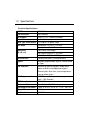
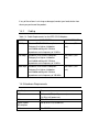
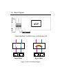
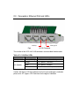
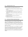
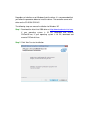
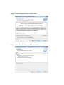
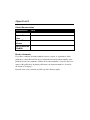
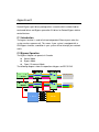
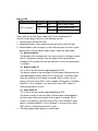
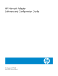
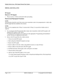
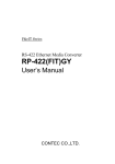
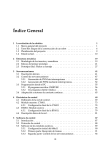
BPC-51243
Quad 1000Base-T Gigabit Ethernet
PCI-E Bypass Adapter
User’s Manual
Revision: 0.3
Table of Contents
1.0 GENERAL INTRODUCTION ...................................................... 2
1.1
OVERVIEW ................................................................................................................................ 3
1.2
KEY FEATURES ......................................................................................................................... 3
1.3
SPECIFICATIONS ....................................................................................................................... 4
1.4
BEFORE YOU BEGIN.................................................................................................................. 5
1.4.1
PRODUCT PACKAGE LIST ......................................................................................................... 5
1.4.2
CABLING ................................................................................................................................... 6
1.4.3
HARDWARE REQUIREMENTS .................................................................................................... 6
1.4.4 SOFTWARE REQUIREMENTS ......................................................................................................... 7
1.5
MECHANICAL DESIGN ............................................................................................................... 8
1.6
BLOCK DIAGRAM ...................................................................................................................... 9
2.0 HARDWARE COMPONENTS................................................... 10
2.1
ADD-ON CARD IMAGE AND LAYOUT ....................................................................................... 11
2.2
MAJOR COMPONENTS ............................................................................................................ 12
2.3
CONNECTORS: ETHERNET PORT AND LEDS ......................................................................... 13
2.4
JUMPERS SETTING & PIN DEFINITION ................................................................................... 14
3.0 INSTALLATION......................................................................... 16
3.1
STATIC-SENSITIVE DEVICES PRECAUTIONS UNPACKING ......................................................... 17
3.2
BEFORE INSTALLATION ........................................................................................................... 17
3.3
INSTALLING THE ADD-ON CARD.............................................................................................. 18
3.4
INSTALLING THE W INDOWS OPERATING SYSTEM .................................................................. 18
3.5
ETHERNET FLASH FIRMWARE UTILITY................................................................................. 23
APPENDIXES ................................................................................. 25
APPENDIXES A ...................................................................................................................................... 25
APPENDIXES B...................................................................................................................................... 26
APPENDIXES C ..................................................................................................................................... 27
APPENDIXES D ..................................................................................................................................... 28
1.0 General Introduction
1.1 Overview
The BPC-51243 is PCI Express x4 interface cards, contains Quad independent
Gigabit Ethernet ports. To enhance Ethernet controller performance, it is
designed with one Intel® i350AM4 Gigabit Ethernet Controller to provide Quad
Gigabit Ethernet ports.
1.2 Key Features
Quad Copper Gigabit Ethernet ports via Intel®i350AM4 controller
IEEE 802.3az Energy Efficient Ethernet
IEEE 1588 Precision Clock Synchronization
Jumbo frame support (9.5KB)
Support PCI-SIG Single-Root I/O virtualization
8 Transmit and 8 Receive queues
Watchdog Timer (WDT) to bypass Ethernet ports on a host system
hang or power failure
Easy configuration of Normal/Bypass model and WDT timer
Built with both onboard LED indicators and LED pin-out for LAN status
and bypass mode, provides variable LED location for system
integration
1.3 Specifications
Technical Specifications:
MODEL
BPC-51243
LAN Controller
Intel i350AM4
OS Support
Linux 2.4, 2.6 , FreeBSD,Windows
Physical Interface
4x RJ-45 female connectors
Card Type and Interface
PCI Express x4 golden finger
Bus width
Generation 2.0 (5 GT/s) x 4 Lane
Operable in x4,x8,16 Slots
Dimension
(W x D x H)
Low Profile, Half Length
168.15(W)x 68.9(D)x 21.5 (H)mm
6.38” (W) x 3.35”(D) x 0.76”(H)
Miscellaneous
Low-profile bracket, full-height bracket
Bypass
Software programmable Bypass, Normal Mode
or Open.
H/W Selection
Selection of normal or bypass model when
power on Built-in watchdog timer bypass
Ethernet ports when host system experiences
hang or power failure
S/W Programmable
WDT Time-out Setting (software programmable
from 1~255 Seconds)
IEEE Compliant
IEEE 802.3
Ethernet of Ports
Quad Copper 1GbE Ethernet ports
Operating Environment
Temp : 0 to 55ºC (32 to 131 ºF) 20 ~ 90% RH
Typical Power
6 Watts
Certification
FCC, CE
IEEE STANDARD /
GIGABIT ETHERNET, 1000BASE-T
NETWORK TOPOLOGY:
Fast Ethernet, 100Base-TX
Ethernet, 10Base-T
Full duplex / Simplex
Support both Simplex & Full duplex operation in
all operating speeds
Auto negotiation:
Auto-negotiation between Full duplex and
simplex operations and between 10Mb/s
100Mb/s speeds and duplex 1000Mb/s.
Data Transfer Rate:
1000 Mb/s, 100 Mb/s and 10 Mb/sec in simplex
mode per port.
2000Mb/s 200 and 20 Mb/s in full duplex mode
per port.
Cables and Operating
distance:
10Base-T Category 3, 4, or 5 maximum 100m *
100Base-Tx Category 5 maximum 100m *
1000Base-T Category 5E maximum 100m *
Queues per port
4 Transmit and 4 Receive queues per port
Priority queuing
802.1p layer 2 priority encoding.
Virtual LANs
802.1q VLAN tagging.
Jumbo Frame
9.5KB
LEDs indicators
Link/Activity/Speed status
1.4 Before you begin
1.4.1
Product Package list
Before beginning installing, please make sure the following items have been
included in the box.
1. BPC-51243 Quad Copper Gigabit Ethernet PCI-E bypass adapter
2. Quick Installation Guide
If any of these items is missing or damaged, contact your local dealer from
whom you purchased the product.
1.4.2
Cabling
Table 1.4. Cable Requirements for the BPC-51243 Adapters
SPEED
CABLE TYPE
MAX DISTAMCE
10 Mbps
Standard TIA/EIA 568-B-compliant
Category 3 or higher shielded or
unshielded cabling with 100 ohm
impedance and a frequency of 16 MHz.
100 meters (328
feet)
100 Mbps
Standard TIA/EIA 568-B-compliant
Category 3 or higher shielded or
unshielded cabling with 100 ohm
impedance and a frequency of 16 MHz.
100 meters (328
feet)
1000 Mbps Standard TIA/EIA 568-A-compliant
Category 5 or higher shielded or
unshielded cabling with 100 ohm
impedance and a frequency of 100 MHz.
100 meters (328
feet)
1.4.3 Hardware Requirements
Specification
Measurement
CPU
Minimum: 1 GHz (x86 processor) or
1.4 GHz (x64 processor)
PCIe
PCIe 2.0 x4 Lane
Typical Power
consumption
6W (0.5A at 12V) Quad Port
Airflow
2 to 25 CFM
1.4.4 Software Requirements
The BPC-51243 supports the following operating systems:
Windows XP x86/x64;
Windows 2003 R2 x86/x64; Windows 2008 x64 SP2;
Windows 7x64
RHEL 5.3 x86/x64
SLES 10 SP2 x64, SLES 11 SP2 x86/x64
Cent OS 5.2 x64, Cent OS 5.3 x86/x64
FreeBSD
1.5 Mechanical Design
The BPC-51243 (Bypass/Non-Bypass) LAN Card is a low profile (half length
and haft height) card with standard or low profile (included) brackets, which
offers flexibility in the configuration and expansion of a computer (desktop PC
or server).
Figure 1.5: BPC-51243 LAN Card PCB Mechanical dimensions
1.6 Block Diagram
Host Interface: 5.0 GT/s Lane x 4 PCIe Gen 2.0
Normal Mode
Bypass Mode
Figure 1.6: BPC-51243 Block Diagram
2.0 Hardware Components
2.1 Add-On Card Image and Layout
I350AM4
LAN Controller
PORT 1
PCIe x4 Edge
PORT 2
PORT 3
PORT 4
Figure 2.1: The BPC-51243 Image
2.2 Major Components
Figure 2.2.1: Jumper & Connector (component side)
Connector
Function
J1
RJ45 connector
J2
PCIE X4 Golden Finger
JP1
Bypass LED connector
JP2
Programming Port for BYPASS Controller B
JP3
Programming Port for BYPASS Controller A
JP4
Hardware Bypass Controller B
JP5
Hardware Bypass Controller A
JP6
Programming Port for CPLD
U1 and U5
MPU
U11
CPLD
U4 and U10 LAN Switch PI3L500
U7
U3 and U9
Intel I350-AM4 LAN Controller
Transformer
Remark
2.3 Connectors: Ethernet Port and LEDs
Activity
Link Speed
Figure 2.3.1 BPC-51243 Faceplate
The function of the LEDs for RJ-45 connectors are described in below table.
Tables 2.3.1 LAN Port LEDs
LED
Color
Definition
Activity
Amber (blinking)
LAN Cable Link & Port Activity
Orange
Link speed in 1000 Mb/s
Green
Link speed in 100 Mb/s
Off
No connection or link speed at 10 Mb/s
Link (Speed)
Caution: No Bypass LED due to board size limit.If you need bypass indication
please refer JP1: bypass LED Connector for the bypass indication.
2.4 Jumpers Setting & Pin Definition
JP1:Bypass LED connector
Pin
Signal Name
Pin
Signal Name
1
BP_A_LEDN
2
BP_A_LEDP
3
NC
4
BP_B_LEDN
5
BP_B_LEDP
JP2:Programming Port for BYPASS Controller B
Pin
Signal Name
1
VPP_B
2
VCC_PIC
3
GND
4
ICSPDAT_B
5
ICSPCLK_B
6
NC
JP3:Programming Port for BYPASS Controller A
Pin
Signal Name
1
VPP_A
2
VCC_PIC
3
GND
4
ICSPDAT_A
5
ICSPCLK_A
6
NC
JP4:Bypass B Control header Definition
Pin
Function
1-2, Short Enable Bypass B define
★
2-3, Short Disable Bypass B define
JP5:Bypass A Control header Definition
Pin
Function
1-2, Short Enable Bypass A define
★
2-3, Short Disable Bypass A define
JP6:Programming Port For CPLD-Bypass
Pin
Signal Name
Pin
Signal Name
1
VCC3
2
BP_TDO_AB
3
BP_TDI_AB
4
GND
5
NC
6
BP_TMS_AB
7
GND
8
BP_TCK_AB
3.0 Installation
3.1 Static-Sensitive Devices Precautions Unpacking
Electrostatic Discharge (ESD) can damage electronic components. To avoid
damaging your add-on card, it is important to handle it very carefully. The
following measures are generally sufficient to protect your equipment from
ESD.
Precautions
Use a grounded wrist strap designed to prevent static discharge.
Touch a grounded metal object before removing a component from the
antistatic bag.
Handle the add-on card by its edges only; do not touch its components,
peripheral chips, memory modules or gold contacts.
When handling chips or modules, avoid touching their pins.
Put the card and peripherals back into their antistatic bags when not in use.
3.2
Before Installation
The Ethernet drivers are supported under Windows, Linux,& FreeBSD. For
other supported drivers, please contact your distributors or sales representative,
or refer to Intel http://downloadcenter.intel.com.
To install the add-on card properly, be sure to follow the instructions below.
Power down the system.
Remove the power cord from the wall socket.
Use industry standard anti-static equipment (such as gloves or wrist strap)
and/or an environment that prevents accidental electrostatic discharge.
Familiarize yourself with the server, motherboard, and/or chassis
documentation.
Confirm that your operating system includes the latest updates and
hotfixes.
3.3
Installing the Add-on Card
Follow the steps below to install the add-on card into your system.
1.
Remove the server cover and, if necessary, set aside any screws for
later use.
2.
Remove the add-on card slot cover. If the case requires a screw, place
the screw aside for later use.
3.
Position the add-on card in the slot directly over the connector, and
gently push down on both sides of the card until it slides into the PCI
connector.
Secure the add-on card to the chassis. If required, use the screw that
you previously removed.
Attach any necessary external cables to the add-on card.
Replace the chassis cover.
Plug the power cord into the wall socket, and power up the system.
4.
5.
6.
7.
3.4
Installing the Windows Operating System
These instructions apply to all versions of Microsoft™ Windows™ 2000,
Windows XP (including Windows XP x64 and Windows XP 64-bit Edition),
Windows Vista™ (including Windows Vista x64), and Windows Server™ 2003
(including Windows Server 2003 x64 and Windows Server 2003 64-Bit Edition).
This driver installation updates the drivers for all supported Intel® PRO network
adapters in your system.
Before installing or updating the drivers, insert your adapter(s) in the computer
and plug in the network cable. When Windows discovers the new adapter, it
attempts to find an acceptable Windows driver already installed with the
operating system. If found, the driver is installed without any user intervention. If
Windows cannot find the driver, the Found New Hardware Wizard window is
displayed.
Regardless of whether or not Windows finds the driver, it is recommended that
you follow the procedure below to install the driver. The controller comes with
driver on the CD-ROM CDR-NIC.
The following steps are manual installation for Windows XP
Step 1 Download the latest Intel I350 driver at http://downloadcenter.intel.com.
If your operating system is 32 Bit, download and execute
PROwin32.exe; If your operating system is 64 Bit, download and
execute PROwinx64.exe
Step 2 Click “Next” to start installation
Step 3 Check the agreement box and click “Next”
Step 4 Select “Default” and press ”Next” to continue
Step 5 Driver installing
Step 6 Click “Finish” to complete the installation
Step 7 Confirm installation successful in Control center > Hardware > device
management
Installing Intel PROSet for Windows Device Manager
Intel PROSet for Windows Device Manager is installed from the Product CD
with the same process used to install drivers. You can select Intel PROSet for
Windows Device Manager and Advanced Network Services from the Install
Options dialog.
Tips for PROSet Users
If you have used prior versions of Intel PROSet, you should be aware of the
following changes with Intel PROSet for Windows Device Manager:
With PROSet:
There is no system tray icon.
The configuration utility is not accessible from the CONTROL PANEL
or the START menu.
All Intel PROSet features are now accessed from DEVICE MANAGER.
To access
features, simply open the DEVICE MANAGER and double-click the
Intel adapter you would like to configure.
Removing Intel PROSet for Windows Device Manager
3.5
Use ADD/REMOVE PROGRAMS from the CONTROL PANEL to
uninstall Intel PROSet for
Windows Device Manager.
Ethernet FLASH Firmware Utility
The Intel® Ethernet Flash Firmware Utility (BootUtil) is a utility that can be used
to program the PCI option ROM on the flash memory of supported Intel PCI and
PCI-Express-based network adapters, and to update configurations. BootUtil
replaces existing utilities and provides the functionality of the older IBAUTIL,
ISCSIUTL, LANUTIL, and FLAUTIL. BootUtil supports all the adapters
supported by the previous utilities.
Intel provides the following flash firmware in FLB file format for programming to
the flash memory:
Intel® Boot Agent as PXE Option ROM for legacy BIOS
http://www.intel.com/support/network/adapter/pro100/bootagent/
Intel® iSCSI Remote Boot as iSCSI Option ROM for legacy BIOS
http://www.intel.com/support/network/iscsi/remoteboot/
Network Connectivity, UEFI network driver
http://www.intel.com/support/network/sb/cs-006120.htm
OEMs may provide custom flash firmware images for OEM network adapters.
Please refer to the instructions given by OEMs.
BootUtil allows the user to flash supported firmware to the adapter from the
included master FLB file. This option ROM includes PXE, iSCSI, FCoE and
UEFI drivers, and the image is programmed to the flash memory at once.
BootUtil will also build the required combo images for supported adapters and
program those images to the flash, as well. Since both discrete and combo
images are supported, the -BOOTENABLE command ONLY works on combo
images.
PXE+EFI and iSCSI+EFI image combinations are supported for all OEM
generic adapters, however support is limited to devices which support both
technologies as discrete images. However, flash size is a limiting factor, as the
image size can change without notice.
Appendixes
Appendixes A
Technical or Customer Support
You can reach Portwell customer support in the following ways:
• Visit the Portwell web site at
http://www.portwell.com/
Returning Merchandise for Service
A receipt or copy of your invoice marked with the date of purchase is required before any
warranty service will be rendered. You can obtain service by calling your vendor for a Returned
Merchandise Authorization (RMA) number. When returning the motherboard to the
manufacturer, the RMA number should be prominently displayed on the outside of the shipping
carton, and the shipping package is mailed prepaid or hand-carried. Shipping and handling
charges will be applied for all orders that must be mailed when service is complete. For faster
service, You can also request a RMA authorization online (http://www.portwell.com).
This warranty only covers normal consumer use and does not cover damages incurred in
shipping or from failure due to the alternation, misuse, abuse or improper maintenance of
products.
During the warranty period, contact your distributor first for any product problems.
Appendixes B
Related Documentation
Documentation
Links
Quick Guide
Bypass Driver on
Linux
Bypass Driver on
Window
Bypass Driver on
FreeBSD
Reader Comments
If you have comments about the technical accuracy, content, or organization of this
publication, contact Portwell. Be sure to include the title and document number of the
publication with your comments. (Online, the document number is located in the front
matter of the publication. In printed publications, the document number is located at
the bottom of each page.)
Portwell values your comments and will respond to them promptly.
Appendixes C
Safety Compliance
• Federal Communications Commission (FCC)
•
•
•
•
Industry Canada Equipment Standard for Digital Equipment
(ICES-003)
EN 60950-1:2006/A11:2009/A1:2010/A12:2011 (European Union)
IEC 60950-1:2005 (2nd Edition); Am 1:2009 (International)
EU LVD Directive 2006/95/EC
RFI Emissions
•
FCC Class B, EN55022 Class B,
FCC Class B User Information
This equipment has been tested and found to comply with the limits for a Class
B digital device pursuant to Part 15 of the FCC rules. These limits are designed
to provide reasonable protection against harmful interference in a residential
installation. This equipment generates, uses and can radiate radio frequency
energy and, if not installed and used in accordance with the instructions, may
cause harmful interference to radio communications. However, there is no
guarantee that interference will not occur in a particular installation.
If this equipment does cause harmful interference to radio or television
reception, which can be determined by turning the equipment off and on, the
user is encouraged to try to correct the interference by one or more of the
following measures:
•
•
•
•
Reorient or relocate the receiving antenna.
Increase the separation between the equipment and receiver.
Connect the equipment into an outlet on a circuit different from that to
which the receiver is connected.
Consult the dealer or an experienced radio/TV technician for help.
Appendixes D
Portwell Bypass-gen3 driver package offers a module which includes Add-on
card model driver and Bypass generation 3.0 driver for Portwell Bypass device
control features.
C-1 Introduction
The bypass function is used to link two independent Ethernet ports when the
system crashes or powers off. This means if your system is equipped with a
LAN Bypass function, a condition in your system will not interrupt your network
traffic.
C-2 Bypass Operation
The Bypass Adapter can operate in 3 modes
Normal Mode
Bypass Mode
Open / Disconnect Mode
The following diagram shows the operation of bypass on BPC-51243
Bypass LED
LED
“B/P” or “Bypass”
Color
Indication Definition
Green
On
LAN in normal mode
On
LAN in bypass mode
Off
LAN in open mode
Red
Please refer to the LAN_Bypass folder on the Driver and Manual CD.
And the Portwell bypass possesses the following features:
1. Communication through SPI BUS.
2. Independent bypass status control for each pair up to a total of 4 pairs
3. Portwell add-on card can bypass systems Ethernet ports on a host system
during three instances: Normal mode, Bypass mode and Open Mode
3.1 Normal mode:S0
The behavior of this configuration is the same as there is no Bypass feature
built-in. The packets coming in from one Bypass Ethernet port will be
handled by CPU and then be sent out thereafter. It exists only when power
is available.
3.2 Bypass mode: S1
This is one of the Non-normal mode depending on BPE.
The packets coming in from one Bypass Ethernet port will be passed to its
corresponding port directly without CPU’s intervention. It can occur when
either out of power or when power is available. When system is out of
power, it will occur when BPE is set to “enabled”. When power is available
and BPE is set to “enabled”, it can occur when either WDT expires or
Software commend is issued.
3.3 Open mode: S2
This is one of the Non-normal mode depending on BPE.
The packets coming in from one Bypass Ethernet port will be dropped. It
can occur when either out of power or when power is available. When
system is out of power, it will occur when BPE is set to “disabled”. When
power is available and BPE is set to “disabled”, it can occur when either
WDT expires or Software commend is issued.
4. Software programmable bypass or normal mode.
5.
Software programmable timer interval
Normal mode watchdog timer, used during normal mode, has timer
setting of 1~255seconds of timer interval.
Run-Time watchdog timer, used during run-time, has setting of 1~255
seconds of timer interval.