1
protect the panel from reverse current during hours of darkness, if the panels
are in shade or if covered by debris (e.g. leaves).
12.2.2.1 Connection process:
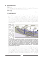
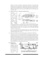
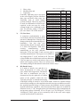
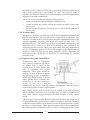
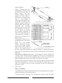
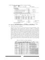
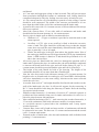
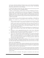
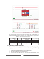
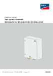
Firstly, it is needed to unscrew the 4 screws in order to open the junction box.
Inside, there will be more screws. But it is needed to unscrew only two screws
- the ones on the bottom left and right, under which there should be a positive
and negative sign. It is not required to disconnect the mounting and diode
connection screws. Then, bring the wires into the junction box via a conduit or
directly with a cable using a rainproof cable connector.
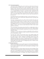
12.2.2.2 Mounting the junction box to a pole:
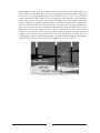
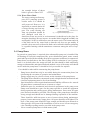
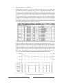
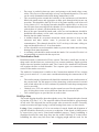
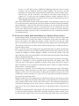
The junction box can be mounted onto the solar array support pole. It clamps
to fit around the mounting pole. This makes a very strong assembly that is easy
to adjust.
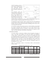
12.2.3 Electrical conduit
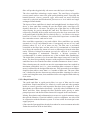
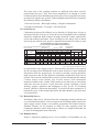
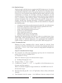
Once the array wiring design, wire size and junction box are decided, it is
needed to decide the number and rating of the fuses and switches. The ratings
of the fuses or circuit breakers are generally kept about 1.5 times the maximum
current flowing. The interconnections among the components are accomplished
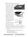
after installation of each component independently. The outdoor wiring must
be protected from human activities, weather and from chewing animals. For
this purpose, it is essential to use electrical conduit (pipe). Use of strong, high
quality outdoor cable is recommended in case of not using the conduit. Where
cables enter the junction box, install sealed strain-relief cable clamps.
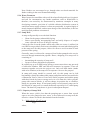
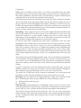
12.2.4 Keeping the electrical conduit and junction box sealed
It becomes prominent for animals, insects, water and dirt to enter through the
holes, so the unused holes must be sealed. Keeping in mind this fact, each hole
is supplied with a rubber plug that can be kept in place for this purpose. It is
important to note that the grounds of system failures are the loose connections.
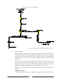
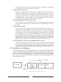
12.3 Installation Line Diagrams
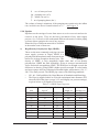
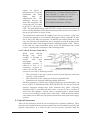
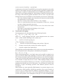
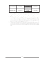
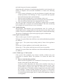
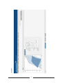
The schematic diagram for water pumping system can be prepared in similar manner
as done with non-pumping applications. However, additional safety device like
water level sensor has to be installed in the system. Moreover, the power conditioning
devices such as maximum power tracker, if required by the pump, may be installed
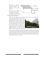
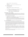
in the system. The suggested installation line diagram for various configurations is
given in the figure below.
Fig. 12-2 Directly coupled DC motor/pump (AEPC, 2003)
101