1
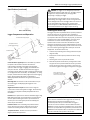
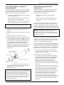
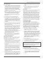
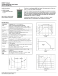
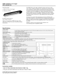
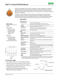
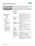
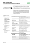
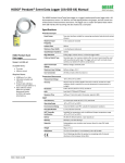
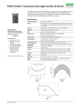
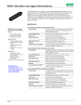
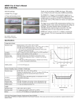
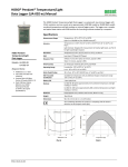
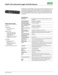
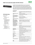
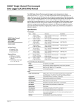
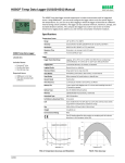
HOBO® Dissolved Oxygen Logger (U26-001) Manual
The HOBO Dissolved Oxygen logger is a standalone logger that uses RDO® Basic Technology
to measure dissolved oxygen (DO). The logger has an optical sensor that provides 0.2 mg/L
accuracy. The logger also features an easily replaceable sensor cap and an integrated
temperature sensor. Using HOBOware® software for logger setup and a HOBO Waterproof
Shuttle for quick data offload, this logger is easy to deploy in both freshwater and saltwater
environments making it an ideal tool for environmental impact studies as well as ecological
and oceanographic research.
Using the data offloaded from the logger, the HOBOware Dissolved Oxygen Assistant can
calculate percent saturation and salinity-adjusted DO concentration as well as correct for
measurement drift from fouling.
HOBO Dissolved Oxygen Logger with
Included Calibration Boot and
Sponge (Shown Wet in Photo)
Specifications
Dissolved Oxygen
HOBO Dissolved
Oxygen Logger
Sensor Type
Optical (dynamic luminescence quenching)
Measurement Range
0 to 30 mg/L
U26-001
Calibrated Range
0 to 20 mg/L; 0 to 35°C (32 to 95°F)
Accuracy
0.2 mg/L up to 8 mg/L; 0.5 mg/L from 8 to 20 mg/L
Resolution
0.02 mg/L
Response Time
To 90% in less than 2 minutes
DO Sensor Cap Life
6 months (cap expires 7 months after initialization)
Included Items:
• Dissolved Oxygen
Sensor Cap
• Protective Guard
• Calibration Boot and
Sponge
Required Items:
• Coupler (COUPLER-2-C)
with USB Optic Base
Station (BASE-U-4) or
HOBO Waterproof Shuttle
(U-DTW-1)
• HOBOware Pro 3.3.1 or
later
Accessories:
• Replacement Dissolved
Oxygen Sensor Cap
(U26-RDOB-1)
• Anti-Fouling Guard
(U26-GUARD-2)
• Sodium Sulfite
(U26-CAL-SOL)
You May Also Need:
• For saltwater, salinity or
conductivity measurements
are required; HOBO
Conductivity/Salinity
Logger (U24-002)
recommended
• For percent saturation,
barometric pressure is
required; HOBO Water
Level Logger (U20-001-0x)
recommended
Temperature
Temperature Measurement/
Operating Range
-5 to 40°C (23 to 104°F), non-freezing
Temperature Accuracy
0.2°C (0.36°F)
Temperature Resolution
0.02°C (0.04°F)
Response Time
To 90% in less than 30 minutes
Logger
Memory
21,700 sets of DO and temperature measurements (64 KB total
memory); logging stops when memory fills
Logging Rate
1 minute to 18 hours
Time Accuracy
±1 minute per month at 0 to 50°C (32 to 122°F) (see Plot A on
next page)
Battery
3.6 V lithium battery; factory replaceable
Battery Life
3 years (at 5 minute logging)
Download Type
Optical
Depth Rating
100 m (328 ft)
Wetted Materials
Black Delrin®, PVC, EPDM o-rings, silicon bronze screws; rated
for saltwater use
Size
39.6 mm diameter x 266.7 mm length (1.56 x 10.5 inches)
Weight
464 g (16.37 oz)
The CE Marking identifies this product as complying with all
relevant directives in the European Union (EU).
15603-A MAN-U26x
Distributed by MicroDAQ.com, Ltd.
www.MicroDAQ.com
(603) 746-5524
HOBO Dissolved Oxygen Logger (U26-001) Manual
Specifications (continued)
WARNING: This logger can be damaged by mechanical
shock. Always handle the logger with care. The logger may be
damaged if it is dropped. Use proper packaging when
transporting or shipping the logger.
Do not attempt to open the logger case or sensor housing.
Disassembling of the logger case or sensor housing will cause
serious damage to the sensor and logger electronics. There are
no user-serviceable parts inside the case. Contact Onset
Technical Support at 1-800-LOGGERS (1-800-564-4377) or an
authorized Onset dealer if your logger requires servicing.
Installing the Sensor Cap
Plot A: Time Accuracy
The logger ships with a replaceable sensor cap that provides six
months of continuous use. Once the cap is initialized, an
internal clock within the logger will count down until the sensor
cap expiration date. When the sensor cap expires, you will need
to replace it with a new cap (U26-RDOB-1). The sensor cap is
intended for six months of actual deployment, but the
expiration date is seven months from the date the cap was
initialized. This allows for any time needed between launching
the logger and physically deploying as well as extra time in case
you are not able to get the logger after exactly six months of
deployment. To install the sensor cap:
Logger Components and Operation
Communications Cap/Lanyard
Temperature Sensor
(Inside Logger Housing)
Protective Guard
Mounting
Hole
Alignment Notch
for Coupler
1. Unscrew the protective guard covering the DO sensor (see
diagram at left).
2. Remove the red dust cap that protects the sensor during
shipping.
DO Sensor
3. Take the green sensor cap out of the canister.
4. With the flat part of the DO sensor pointing down and the
the green sensor cap oriented with the arrow up, slide the
sensor cap over the sensor until it snaps in place. The cap
should be snug against the logger housing without any gaps.
Communications Cap/Lanyard. This removable cap protects
the optical communications window. An LED in the
communications window of the logger confirms logger
operation. When the logger is logging, the LED blinks once
every four seconds. The LED also blinks when the logger is
recording a sample. When the logger is awaiting a start because
it is configured to start “At Interval,” “On Date/Time,” or “Using
Coupler,” the LED blinks once every eight seconds until logging
begins. See Connecting the Logger to a Computer or
Waterproof Shuttle for details on using the communications
window.
Sensor cap with arrow
positioned up; slide over DO
sensor until it snaps in place
Mounting Hole. Use the hole on the communications cap to
mount the logger. See Deploying the Logger for more
information.
DO sensor, flat
side down
Alignment Notch for Coupler. Use this notch to align the
coupler when communicating with the logger. See Connecting
the Logger to a Computer or Waterproof Shuttle for more
information.
5. Screw the external protective guard back on until tight.
DO Sensor. This optical sensor measures dissolved oxygen using
RDO® Basic Technology. It is shipped with a red dust cap that
must be replaced with a green sensor cap that lasts for six
months plus a one-month grace period. See Installing the
Sensor Cap for more details.
Important: The sensor cap expires seven months (to the day)
after it has been initialized and the logger will not collect any
data after the cap has expired. Initialization occurs
automatically when the cap is installed after the logger is
launched. You can also initialize it from the Status window in
HOBOware or when using the Lab Calibration tool. To see when
the sensor cap expires after being initialized, check the Status in
HOBOware for the expiration date. The cap also has a shelf life;
check the “Install By” date printed on the canister.
Protective Guard. This removable guard protects the DO
sensor. Unscrew it to install or replace the sensor cap as
needed. See Installing the Sensor Cap for more details.
Temperature Sensor. This built-in sensor (not visible in
diagram) measures temperature.
1-800-LOGGERS
Distributed by MicroDAQ.com, Ltd.
2
www.MicroDAQ.com
www.onsetcomp.com
(603) 746-5524
HOBO Dissolved Oxygen Logger (U26-001) Manual
Connecting the Logger to a Computer or
Waterproof Shuttle
Calibrating the Logger with the Lab
Calibration Tool
To connect the logger to a computer, use either the Optic USB
Base Station (BASE-U-4) or HOBO Waterproof Shuttle (U-DTW1) with a coupler (COUPLER2-C). To launch and read out the
logger in the field, use one of these three methods:
Use the Lab Calibration tool in HOBOware when you need to
calibrate the logger before deploying it or after replacing an
expired sensor cap. The tool sets the gain and offset
adjustment values for the logger by:
• Laptop computer with Optic USB Base Station (BASE-U-4)
and coupler (COUPLER2-C)
• Restoring logger calibration values to the factory
defaults,
• HOBO Waterproof Shuttle (U-DTW-1, Firmware Version
3.2.0 or later) and coupler (COUPLER2-C)
• Using your own gain and offset adjustment values, or
• Calculating the values with a three-step calibration
procedure.
• HOBO U-Shuttle (U-DT-1, Firmware Version 1.16 or later)
with Optic USB Base Station and coupler (COUPLER2-C)
In the three-step procedure, the logger is first calibrated to
100% saturation by placing it in water-saturated air. Then, you
can calibrate the logger to 0% saturation by placing it in sodium
sulfite or another 0% oxygen environment (recommended if the
logger will be deployed in water with DO levels of 4 mg/L or less).
IMPORTANT: USB 2.0 specifications do not guarantee
operation outside the range of 0°C (32°F) to 50°C (122°F).
1. Follow the instructions that came with your base station or
Waterproof Shuttle to attach it to a USB port on the
computer.
IMPORTANT: Lab calibration only affects future launches; any
data saved in the logger will be based on the previous
calibration values. If the sensor cap is installed and it has not
yet been initialized, you will be prompted to do so. Follow the
instructions on the screen.
2. Unscrew the pointed cap on the communications end of the
logger.
3. Attach the coupler to the base station or shuttle.
To complete these steps, you will need fresh water, the
calibration boot and sponge supplied with the logger, and a
source for current barometric pressure at your current location.
You will also need sodium sulfite solution and a 7.6 cm (3 inch)
beaker if you will be calibrating to 0% saturation.
4. Insert the logger into the coupler, aligning the bump/arrow
on the coupler with the notches on the logger. Be sure that
it is properly seated in the coupler. If the logger has never
been connected to the computer before, it may take a few
seconds for the new hardware to be detected by the
computer. Note: If you are using the HOBO Waterproof
Shuttle as a base station with a computer, briefly press the
coupler lever to put the shuttle into base station mode. A
green LED on the shuttle or base station indicates good
communication.
The fresh water, logger, and sodium sulfite (if applicable) should
be left out in the lab where the calibration is being done long
enough so that they are at room temperature. If the logger was
deployed previously, make sure the sensor is clean and dry (see
Maintenance for more details). To use the Lab Calibration tool:
1. Connect the logger to the computer as described in the
previous section. Stop the logger if it is currently logging or
awaiting a coupler or delayed start.
Notches in logger; use to
align with bump in coupler
2. From the Device menu, click Lab Calibration.
Bump on coupler
3. The current gain and offset adjustments are displayed in
the top pane of the Lab Calibration window along with the
date and time the last lab calibration was completed (if
applicable). Completing Steps 1 through 3 in the Lab
Calibration tool will result in new gain and offset
adjustment values based on the current logger conditions.
Continue to the next section for details on how to complete
these steps.
Communications end of logger
To base station
or shuttle
Coupler lever
5. After logger communications are complete, remove the
logger from the coupler. Make sure the o-ring is still in the
groove inside the cap and then reinstall the
communications cap.
If you already know what the gain and offset values should
be (for example, the values from a previous calibration that
you want to use again) or want to return to the default
factory values, click the “I know my values, skip to Finish”
button. This will automatically move you to “Step 3: Finish”
in the Lab Calibration window. Either click the “Reset to
Factory Defaults” button or type in the desired gain
adjustment and offset adjustment values and click the
“Send Calibration to the Logger” button. Note: If you decide
you do not need to change the calibration, click Close to
cancel the calibration and revert back to the last saved
logger values.
IMPORTANT: When connected to a coupler, the logger is
“awake” and consumes significantly more power than when it
is disconnected and considered “asleep.” The logger will
automatically “go to sleep” after being left in the coupler for 30
minutes. It will no longer appear as a USB device connected to
the computer. If this occurs, remove it from the coupler and
start the instructions to connect the logger to a computer or
waterproof shuttle over again.
1-800-LOGGERS
Distributed by MicroDAQ.com, Ltd.
3
www.MicroDAQ.com
www.onsetcomp.com
(603) 746-5524
HOBO Dissolved Oxygen Logger (U26-001) Manual
Step 1: 100% Saturation
button click, then temperature equilibrium has likely been
reached.
1. In “Step 1: 100% Saturation” in the Lab Calibration window,
enter the barometric pressure for your current location. If
the barometric pressure reading has been adjusted for sea
level (such as a reading taken from the National Weather
Service weather station), select the “If using sea level
barometric pressure, enter elevation” checkbox and enter
your elevation in either meters or feet.
6. When you are satisfied with the results displaying in the
“Step 2: 0% Saturation” tab, click the Next button to
proceed to “Step 3: Finish.”
Step 3: Finish
The results from the first two steps are displayed as well as the
overall calibration results and the new gain and offset
adjustment values. If you are satisfied with the results, click the
“Send Calibration to Logger” button. The logger will then be
calibrated based on the new values. These values will not take
effect until the logger is launched. If you do not want to save
these values, click Close to cancel the calibration and revert
back to the last saved logger values. Or, click “Reset to Factory
Defaults” to return to the original values. If you performed Step
2, then remove the logger from the solution and thoroughly
rinse it with fresh water to remove any excess sodium sulfite.
See Maintenance for additional details on cleaning the logger.
2. Make sure the logger either has the protective guard or the
anti-fouling guard installed (whichever guard you plan to
use in the deployment) so that the sensor is covered.
3. Wet the small sponge with fresh water. Squeeze out any
excess water.
4. Place the sponge in the end of the calibration boot.
5. Insert the logger in the calibration boot so that there is
approximately a 1 cm (0.5 inch) overlap between the end of
the boot and the body of the logger. This will ensure there
is enough space between the end of the logger and the
sponge (the logger should not be pressed up tightly against
the sponge).
Launching the Logger
After calibrating the logger, it needs to be launched to
configure it before taking it to the field for deployment. Once
launched, the logger will record two types of data: samples and
events. Samples are the sensor measurements recorded at
each logging interval. Events are independent occurrences
triggered by a logger activity, such as Bad Battery or Host
Connected. Events help you determine what was happening
while the logger was logging. To launch the logger:
6. Wait for approximately 15 minutes until the logger reaches
temperature equilibrium (and less than 30 minutes so the
logger does not go to sleep).
7. Click the “Get DO value from the logger” button to display
the 100% saturation results. You can click this button as
often as needed. The results are updated each time you
click the button. To check for equilibrium, click the “Get DO
value from the logger” button several times in a row to
check the current “DO Conc from logger at 100%
Saturation” value. If the value remains the same or varies
very little with each button click, then temperature
equilibrium has likely been reached.
1. With the logger connected to the computer, open
HOBOware. From the Device menu, select Launch.
2. Select both the DO and Temperature channels to log. Note:
HOBOware provides the option of recording the current
battery voltage at each logging interval, which is disabled by
default. Recording battery life at each logging interval takes
up memory and therefore reduces logging duration. It is
recommended that you only record battery voltage for
diagnostic purposes. Even with the channel disabled, a bad
battery event will still be recorded.
8. When you are satisfied with the results displaying in the
“Step 1: 100% Saturation” tab, click the Next button to
proceed to “Step 2: 0% Saturation.”
Step 2: 0% Saturation (optional)
If the logger will be deployed in water with DO levels greater
than 4 mg/L, click the “Skip this Step” button. Otherwise,
continue with the following procedure.
3. Select a logging interval.
4. Choose when to start logging and click the Start button.
1. Make sure the logger either has the protective guard or the
anti-fouling guard installed (whichever guard you plan to
use in the deployment) so that the sensor is covered.
5. Remove the logger from the coupler and screw the
communications cap back on the logger.
IMPORTANT: If this is the first launch with a new sensor cap,
the sensor cap will expire six months (plus a one-month grace
period) from the time of the first sensor reading. Two caps per
year are required for year-round deployment.
2. Pour the sodium sulfite into the beaker so that it is about
two-thirds full.
3. Place the sensor end of the logger into the solution so that
the entire protective guard or anti-fouling guard and at
least 2.5 cm (1 inch) of the logger body are submerged in
the beaker. Allow it to rest on the bottom of the beaker.
Deploying the Logger
The logger is designed to be easy to deploy in many
environments. Follow these guidelines when deploying it:
4. Wait for approximately 15 minutes until the logger reaches
temperature equilibrium (and less than 30 minutes so the
logger does not go to sleep).
• Remove the calibration boot before deploying the logger.
• Make sure the logger is located where it will receive an
unrestricted flow of the water being monitored to the
sensor.
5. Click the “Get DO value from the logger” button to display
the 0% saturation results. As with the 100% calibration, you
can click this button as often as needed. The results are
automatically updated each time you click the button. If the
value remains the same or varies very little with each
1-800-LOGGERS
Distributed by MicroDAQ.com, Ltd.
4
www.MicroDAQ.com
www.onsetcomp.com
(603) 746-5524
HOBO Dissolved Oxygen Logger (U26-001) Manual
• Make sure the logger is fully submerged and not in direct
sunlight to minimize temperature changes that are
unrelated to water temperature.
meter or by titration. If using a meter, make sure it is
calibrated and allow time for the meter probe to stabilize
(this will occur when three meter measurements taken in a
row are within your accuracy tolerance).
• When deploying the logger in rivers, streams, and ponds,
insert the logger in a PVC or ABS pipe for protection from
debris (if possible). The pipe should have enough holes to
ensure good circulation of water to the sensor.
If the logger is being deployed in saltwater, adjust the
meter measurements for salinity using a meter with both
conductivity and DO probes. If the saltwater has a constant
salinity, you can use a DO meter where you can enter that
salinity value to adjust the readings. If the salinity and/or
DO are changing rapidly, then you will need to get a sample
of the water in a container large enough for both the logger
and meter probe to be completely submerged. Place both
devices in the water long enough for them to stabilize and
then for the DO logger to log at least two values, and take a
concurrent meter reading.
• If possible, position the logger so the sensor face is
oriented vertically. After deploying in the water, move
the logger around slightly to eliminate any bubbles that
may have formed.
• Do not deploy the logger in freezing water with moving ice
where the logger could be crushed.
• Use the optional anti-fouling guard to protect against
fouling. Unscrew the protective guard and replace it with
the anti-fouling guard.
2. Record the reading, date, and time of the measurement in a
field notebook.
• If fouling is expected during deployment, use field
calibration readings from both the beginning and end of
the deployment as described in the next section. These
readings can then be entered into the HOBOware
Dissolved Oxygen Assistant to compensate for any
measurement drift due to fouling. Scrub fouling off the
logger with a plastic bristle brush.
3. At the end of the deployment, repeat steps 1 and 2.
• When deploying the logger in saltwater, you will need a
conductivity value to enter in the Dissolved Oxygen
Assistant that adjusts the data from the logger for
salinity. If the salinity is constant through the
deployment, you will need a single salinity reading from
either a conductivity meter or salinometer. However, if
the conductivity changes, then you will need a data file
with salinity or specific conductivity readings for the
entire deployment. Consider deploying a HOBO
Conductivity logger (U24-002) next to this DO logger to
use the resulting data file for salinity data.
2. If the logger has been in salt water, clean the logger body
and sensor cap as described in the Maintenance section.
Make sure the sensor cap is dry before continuing.
To Take Calibration Readings Using 100% Water-Saturated Air:
1. The logger must be logging. You will need fresh water, the
included calibration boot and sponge, and the current
barometric pressure from a HOBO U20 Water Level logger,
a barometer, or a nearby weather station.
3. Make sure the protective guard or anti-fouling guard is
installed on the logger.
4. Wet the small sponge with fresh water. Squeeze out any
excess water.
5. Place the sponge in the end of the calibration boot.
6. Insert the logger in the calibration boot so that there is
approximately a 1 cm (0.5 inch) overlap between the end of
the boot and the body of the logger. This will ensure there
is enough space between the end of the logger and the
sponge (the logger should not be pressed up tightly against
the sponge).
• To generate a percent saturation series, you will need to
deploy a barometric pressure logger (such as a HOBO
Water Level Logger, U20-001-0x) or have access to a
nearby weather station to gather barometric pressure
data. This data is necessary for the Dissolved Oxygen
Assistant to calculate percent saturation.
7. Allow at least 40 minutes for the logger to reach
temperature equilibrium, and then write down the date and
time in a field notebook.
Taking Field Calibration Readings
If fouling is expected during the deployment, you can take
calibration readings at the beginning and end of the
deployment to enter in the Dissolved Oxygen Assistant. This will
adjust the data from the logger to compensate for any
measurement drift due to fouling. There are two methods for
taking field calibration readings: the first method involves
taking readings using a dissolved oxygen meter or titration
while the second method involves calibrating the logger in
100% water-saturated air. The first method is recommended
because it is quicker to get the necessary calibration readings;
the second method can take 40 minutes or more to achieve
equilibrium with temperature extremes.
8. Write down the barometric pressure at that time (note the
elevation if the barometric reading has been adjusted for
sea level).
To Take Calibration Readings Using a DO Meter or Titration:
2. If the logger was in saltwater and you did not deploy a
HOBO Conductivity Logger, then use a conductivity meter
or salinometer to take a conductivity reading. Write down
the reading and the date and time.
9. Repeat these steps at the end of the deployment.
Reading Out the Logger and Redeploying
Your readout and maintenance schedule will be determined by
the amount of fouling at the site. To read out the logger in the
field:
1. Take a field calibration reading as described in the Taking
Field Calibration Readings section.
1. The logger must be logging. Take a DO measurement of the
water where the logger is being deployed using either a DO
1-800-LOGGERS
Distributed by MicroDAQ.com, Ltd.
5
www.MicroDAQ.com
www.onsetcomp.com
(603) 746-5524
HOBO Dissolved Oxygen Logger (U26-001) Manual
3. Remove the logger from the water and read out the data
from the logger using a shuttle or computer with a base
station.
4. If you are deploying it again, clean the sensor (see
Maintenance for details).
5. Check the expiration date for your cap and make sure it will
not expire before the end of your deployment. Replace it if
needed.
6. Relaunch the logger if it is not already logging.
7. Take another field calibration reading after the logger is
cleaned.
8. Redeploy the logger.
deployments, keep it in the calibration boot (wet the small
sponge with fresh water, place the sponge in the end of the
calibration boot, and then insert the logger in the boot.)
WARNING: Do not use organic solvents; they will damage
the sensor. Do not remove the sensor cap from the sensor prior
to cleaning with a brush. Only clean the sensor when you
replace the sensor cap. See the full instructions that ship with
the replacement sensor cap. Do not wet the sensor optical lens
area with water or any solution. Remove the cap and gently
wipe the window with a soft cloth.
To clean the logger body:
1. Make sure the sensor cap is installed on the logger.
Using the HOBOware Dissolved
Oxygen Assistant
2. Gently scrub the logger body with a plastic bristle brush or
nylon dish scrubber.
Use the Dissolved Oxygen Assistant to obtain accurate
Dissolved Oxygen readings if the logger was deployed in a
saltwater environment or if percent saturation is required. Also
use this assistant if you took field calibration readings. The
Dissolved Oxygen Assistant is only available in HOBOware from
the Plot Setup window when you open a file from this logger.
To use the assistant:
3. Use Alconox® to remove grease.
1. Offload the most recent data files from the shuttle or logger
to your computer.
2. Open a data file in HOBOware.
3. In the Plot Setup window, select the Dissolved Oxygen
Assistant and click Process.
4. In the Dissolved Oxygen Assistant window, enter the
salinity, barometric pressure, and field calibration
information as needed. Click the Help button in the
Dissolved Oxygen Assistant for more details and to learn
about the ranges of input data allowed.
5. Plot the data and save it as a project file.
Maintenance
To clean the sensor cap:
1. Remove the protective guard or anti-fouling guard, but
leave the sensor cap on the sensor.
2. Rinse the logger with clean water from a squirt bottle or
spray bottle.
3. Gently wipe the cap with a soft-bristled brush (such as a
toothbrush) or soft cloth if biofouling is present. Use
Alconox® to remove grease.
4. If extensive debris or mineral build-up is present, soak the
cap end in vinegar for 15 minutes, then soak it in deionized
(DI) water for another 15 minutes.
5. If the logger is being immediately redeployed with the same
sensor cap, a field calibration is adequate. If a new sensor
cap is being installed, a lab calibration with HOBOware is
recommended. When storing the logger between
1-800-LOGGERS (564-4377) • 508-759-9500
www.onsetcomp.com • [email protected]
4. Soak in vinegar to remove mineral deposits.
5. Rinse the logger with deionized (DI) water.
Battery Guidelines
The battery life of the logger should be three years or more.
Actual battery life is a function of the number of deployments,
logging interval, and operation/storage temperature of the
logger. Frequent deployments with fast logging intervals,
continuous storage/operation at temperatures above 35°C
(95°), and keeping the logger connected to the coupler will
result in significantly lower battery life. For example, the
battery may last less than a year with a 1-minute logging
interval. To obtain a three-year battery life, a logging interval of
five minutes or greater should be used and the logger should be
operated and stored at temperatures between 0° and 25°C (32°
and 77°F).
The logger can report and log its battery voltage. If the battery
falls below 3.2 V, the logger will record a “bad battery” event in
the datafile. The logger will record a second “bad battery”
event and stop logging when the battery falls below 3.1 V. If the
datafile contains “bad battery” events, the logger should be
returned to Onset for battery replacement. Note the logger
does not have to be recording the battery channel for it to
detect bad battery events. The logger will record these events
regardless of what channels are logged. To have your logger’s
battery replaced, contact Onset or your place of purchase for
return arrangements. Do not attempt to replace the battery
yourself. Severe damage to the logger will result if the case is
opened without special tools, and the warranty will be voided.
WARNING: Do not cut open, incinerate, heat above 100°C
(212°F), or recharge the lithium battery. The battery may
explode if the logger is exposed to extreme heat or conditions
that could damage or destroy the battery case. Do not dispose
of the logger or battery in fire. Do not expose the contents of
the battery to water. Dispose of the battery according to local
regulations for lithium batteries.
© 2012 Onset Computer Corporation. All rights reserved. Onset, HOBO, and HOBOware are
trademarks or registered trademarks of Onset Computer Corporation. RDO is a registered
trademark of In-Situ® Inc., Fort Collins, CO USA. All other trademarks are the property of their
respective companies.
15603-A MAN-U26x
Distributed by MicroDAQ.com, Ltd.
www.MicroDAQ.com
(603) 746-5524