1
User’s Manual
CONCEPT 500 TGT
User's Manual
CONCEPT 500 TGT
pt
e
nc
Co
0
50
T
TG
Edition AA, September 2014
This book has part No 10076069 (GB)
0-2
General information
This manual
Part 0: General information
This manual
Products covered
This manual is valid for:
CONCEPT 500 TGT from serial no 366.001.
The serial number is specified on the equipment name plate located on the rear end of
the equipment.
#
Always read the Safety Instruction Manual part No 21741 before installing or
operating the equipment.
This manual is published by:
Glunz & Jensen S.p.A.
Via Alessandro Volta 28
20088 – Rosate (MI) – ITALY
Tel.: +39 02 900 90 180 – Fax: +39 02 900 90 149
Internet: www.degraf.glunz-jensen.com
Copyright © 2015 by Glunz & Jensen S.p.A.
User's Manual - CONCEPT 500 TGT
1437
General information
About this manual
About this manual
Intended use of this manual
This manual describes the common use procedures of the equipment. It is intended for
the daily user and should be kept with the equipment for reference at all times.
Reservations
• This manual was written and illustrated using the best possible information
available at the time of publication.
• Any differences between this manual and the equipment reflect improvements
introduced after the publication of the manual.
• Changes, technical inaccuracies and typographic errors will be corrected in
subsequent editions.
• As a part of our policy of continuous improvement, we reserve the right to alter
design and specifications without further notice.
Notes, cautions, and warnings !
Throughout the manual notes, cautions, and warnings are written in bold like the
example below:
"
Electrical installation must conform to local regulations and guidelines.
Symbol
"
$
#
1437
Meaning
Explanation
Note
The operator should observe and/or act according to the
information in order to obtain the best possible function of
the equipment.
Caution
The operator must observe and/or act according to the
information in order to avoid any mechanical or electrical
damage to the equipment.
Warning
The operator must observe and/or act according to the
information in order to avoid any personal injury.
User's Manual - CONCEPT 500 TGT
0-3
0-4
General information
About this manual
Unintended use of the equipment
Glunz & Jensen S.p.A. does not take any responsibility for any damage or accidents
caused by unintended use of the equipment:
• It is absolutely prohibited to make any modifications, electrical nor mechanical, of
the equipment. If however this prohibition is disregarded, Glunz & Jensen warranty
will no longer apply.
Intended use of the equipment
• This equipment is designed to give the operator an instrument of absolute reliability
for the control of thickness and depth of relief in the flexographic plates.
Installation
• Never install the equipment in explosive environments.
• It is the responsibility of the owner and operator/s of this equipment that the
installation is made in accordance with local regulations, and by engineers
authorized to carry out electrical installations.
• Installation, service and repair must be performed only by Service Technicians who
are trained in servicing the equipment.
• The manufacturer cannot be held responsible for any damage caused by incorrect
installation of this equipment.
• The equipment is intended for installation in a restricted access location only.
Service assistance
• If help is needed to correct any problem with the equipment, please contact your
supplier.
User's Manual - CONCEPT 500 TGT
1437
General information
Table of contents
Table of contents
Part 0: General information . . . . . . . . . . . . . . . . . . . . . . . . . . . . . . 0-2
This manual. . . . . . . . . . . . . . . . . . . . . . . . . . . . . . . . . . . . . . . . . . . . . . . . . . . . . 0-2
Products covered . . . . . . . . . . . . . . . . . . . . . . . . . . . . . . . . . . . . . . . . . . . . . . . 0-2
About this manual . . . . . . . . . . . . . . . . . . . . . . . . . . . . . . . . . . . . . . . . . . . . . . . . 0-3
Intended use of this manual . . . . . . . . . . . . . . . . . . . . . . . . . . . . . . . . . . . . . . . 0-3
Reservations . . . . . . . . . . . . . . . . . . . . . . . . . . . . . . . . . . . . . . . . . . . . . . . . . . 0-3
Notes, cautions, and warnings ! . . . . . . . . . . . . . . . . . . . . . . . . . . . . . . . . . . . . . 0-3
Unintended use of the equipment. . . . . . . . . . . . . . . . . . . . . . . . . . . . . . . . . . . . 0-4
Intended use of the equipment. . . . . . . . . . . . . . . . . . . . . . . . . . . . . . . . . . . . . . 0-4
Installation . . . . . . . . . . . . . . . . . . . . . . . . . . . . . . . . . . . . . . . . . . . . . . . . . . . 0-4
Service assistance . . . . . . . . . . . . . . . . . . . . . . . . . . . . . . . . . . . . . . . . . . . . . . 0-4
Part 1: Technical specifications. . . . . . . . . . . . . . . . . . . . . . . . . . . . 1-1
General environmental information . . . . . . . . . . . . . . . . . . . . . . . . . . . . . . . . . . . . . 1-1
The equipment does not contain . . . . . . . . . . . . . . . . . . . . . . . . . . . . . . . . . . . . 1-1
Batteries . . . . . . . . . . . . . . . . . . . . . . . . . . . . . . . . . . . . . . . . . . . . . . . . . . . . . 1-1
Recycling . . . . . . . . . . . . . . . . . . . . . . . . . . . . . . . . . . . . . . . . . . . . . . . . . . . . 1-1
Electrical specifications . . . . . . . . . . . . . . . . . . . . . . . . . . . . . . . . . . . . . . . . . . . . . 1-1
Mechanical specifications . . . . . . . . . . . . . . . . . . . . . . . . . . . . . . . . . . . . . . . . . . . 1-2
Dimensions . . . . . . . . . . . . . . . . . . . . . . . . . . . . . . . . . . . . . . . . . . . . . . . . . . . 1-2
Weights . . . . . . . . . . . . . . . . . . . . . . . . . . . . . . . . . . . . . . . . . . . . . . . . . . . . . 1-2
Part 2: Daily use . . . . . . . . . . . . . . . . . . . . . . . . . . . . . . . . . . . . . . 2-1
General . . . . . . . . . . . . . . . . . . . . . . . . . . . . . . . . . . . . . . . . . . . . . . . . . . . . . . . . 2-1
Initial operation of the equipment . . . . . . . . . . . . . . . . . . . . . . . . . . . . . . . . . . . . . . 2-1
Equipment description . . . . . . . . . . . . . . . . . . . . . . . . . . . . . . . . . . . . . . . . . . . . . 2-2
Measuring instrument . . . . . . . . . . . . . . . . . . . . . . . . . . . . . . . . . . . . . . . . . . . . . . 2-3
LCD display . . . . . . . . . . . . . . . . . . . . . . . . . . . . . . . . . . . . . . . . . . . . . . . . . . . 2-4
Basic operations. . . . . . . . . . . . . . . . . . . . . . . . . . . . . . . . . . . . . . . . . . . . . . . . 2-5
Starting/stopping the measuring instrument. . . . . . . . . . . . . . . . . . . . . . . . . . . 2-6
Switching the resolution . . . . . . . . . . . . . . . . . . . . . . . . . . . . . . . . . . . . . . . . 2-6
Switching the measurement system . . . . . . . . . . . . . . . . . . . . . . . . . . . . . . . . 2-6
Setting the origin . . . . . . . . . . . . . . . . . . . . . . . . . . . . . . . . . . . . . . . . . . . . . 2-7
Measurement modes . . . . . . . . . . . . . . . . . . . . . . . . . . . . . . . . . . . . . . . . . . 2-8
Analog display . . . . . . . . . . . . . . . . . . . . . . . . . . . . . . . . . . . . . . . . . . . . . . 2-11
Switching the counting direction . . . . . . . . . . . . . . . . . . . . . . . . . . . . . . . . . 2-11
Locking the buttons . . . . . . . . . . . . . . . . . . . . . . . . . . . . . . . . . . . . . . . . . . 2-11
Data input and output. . . . . . . . . . . . . . . . . . . . . . . . . . . . . . . . . . . . . . . . . . . 2-12
Output connector . . . . . . . . . . . . . . . . . . . . . . . . . . . . . . . . . . . . . . . . . . . . 2-12
Output data format (DATA1) . . . . . . . . . . . . . . . . . . . . . . . . . . . . . . . . . . . . 2-12
Timing chart . . . . . . . . . . . . . . . . . . . . . . . . . . . . . . . . . . . . . . . . . . . . . . . 2-13
Part 3: Measuring plate thickness . . . . . . . . . . . . . . . . . . . . . . . . . . 3-1
1437
User's Manual - CONCEPT 500 TGT
0-5
0-6
General information
Table of contents
Part 4: Troubleshooting . . . . . . . . . . . . . . . . . . . . . . . . . . . . . . . . . 4-1
General . . . . . . . . . . . . . . . . . . . . . . . . . . . . . . . . . . . . . . . . . . . . . . . . . . . . . . . . 4-1
Part 5: Spare parts . . . . . . . . . . . . . . . . . . . . . . . . . . . . . . . . . . . . 5-1
General . . . . . . . . . . . . . . . . . . . . . . . . . . . . . . . . . . . . . . . . . . . . . . . . . . . . . . . . 5-1
Ordering spare parts . . . . . . . . . . . . . . . . . . . . . . . . . . . . . . . . . . . . . . . . . . . . . 5-1
Finding a spare part . . . . . . . . . . . . . . . . . . . . . . . . . . . . . . . . . . . . . . . . . . . . . 5-1
Thickness gauge table . . . . . . . . . . . . . . . . . . . . . . . . . . . . . . . . . . . . . . . . . . . . . . 5-3
User's Manual - CONCEPT 500 TGT
1437
Technical specifications
General environmental information
Part 1: Technical specifications
General environmental information
The equipment does not contain
• Ozone depleting substances according to Montreal protocol
• Asbestos
• Polychlorinated biphenyl or Poly- Cyclohexylenedimethylene Terephthalate
• Cadmium
• Lead as additive to plastic parts
Batteries
No batteries in this equipment.
Recycling
The equipment should be disposed at a certified appliance recycling centre or
processing centre.
Electrical specifications
AC adapter is delivered with the equipment.
Power supply
1437
AC adapter, 9 V, 500 mA
User's Manual - CONCEPT 500 TGT
1-1
1-2
Technical specifications
Mechanical specifications
Mechanical specifications
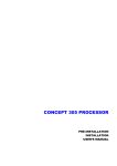
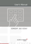
Dimensions
m
5 m")
1
12 7.8
(4
13
60
(5 mm
3.5
")
m
0 m")
6
1 3 3.5
(5
mm
00 1")
4
1 5.
(5
15
50
(6 mm
1"
)
mm
20 8")
6
1 3.
(6
T33276
Weights
Weight, crated (± 5%)
Weight, equipment
User's Manual - CONCEPT 500 TGT
approx. 460 kg (1014 lb)
approx. 180 kg (397 lb)
1437
Daily use
General
Part 2: Daily use
General
This equipment is designed to give the operator an instrument of absolute reliability
for the control of thickness and depth of relief in the flexographic plates. In the
measuring process uses gravity, so there is no pressure on plate. This plate gauge
measuring table is controlled by foot switch/pedal and is intended for any plate size. It
is possible to set a tolerance, so an alarm triggers if the measurement is outside the
tolerance.
This equipment is equipped with a specific control panel which ensures very easy
control.
Initial operation of the equipment
"
Make sure the room temperature is between 17 and 28°C (63 and 82°F) and
relative humidity on max. 80%.
"
Before turning the equipment on make sure that the working area around the
equipment is clean and free for easy movement.
"
Check the power cable.
• Remove the DC jack cover at the top of the display. Insert the DC plug of the AC
adapter delivered with the equipment securely into the DC IN jack.
• Insert the AC plug at the other end securely into a power outlet or extension cord.
• As soon as power is supplied, LCD appears and back light turns on.
$
Before shutting off the power supply, always press the ON/OFF button to turn
the measuring instrument off. Shutting off the power while measuring
instrument is operating can damage origin and other memory data.
• Press the ON/OFF button to start (begin) and stop (end) the measuring instrument.
1437
User's Manual - CONCEPT 500 TGT
2-1
2-2
Daily use
Equipment description
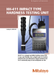
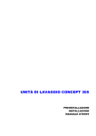
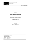
Equipment description
The equipment consists from the three main parts:
• foot switch/pedal (1),
• measuring table (2),
• measuring instrument (3).
3
2
0
50
T
TG
1
T11413
User's Manual - CONCEPT 500 TGT
1437
Daily use
Measuring instrument
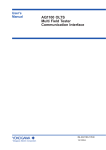
Measuring instrument
9
8
7
10
11
6
12
5
13
4
3
14
2
1
T33259
1437
Item
Description
Item
1
Contact point
6
2
Spindle
3
Item
Description
Release hole (from side)
11
RES button
7
+/– button
12
ZERO/ABS button
Stem
8
DC jack
13
PRESET/SET button
4
MODE button
9
Output connector
14
RANGE/®Adj.¬ button
5
ON/OFF button
-
AC adapter (not shown)
10
Description
LCD display
User's Manual - CONCEPT 500 TGT
2-3
2-4
Daily use
Measuring instrument
LCD display
5
6
4
3
2
1
7
8
16
9
15
10
11
12
13
Item
Description
Item
1
Analog range
7
Hold sign
13
Max. peak hold mode
2
Upper over range
8
Function lock
14
Unit
3
Upper pointer (flashes)
9
Comparison measure
15
Preset the origin
4
Pointer
10
Reverse count measure
16
5
Lower pointer (flashes)
11
Min. peak hold mode
GO/NG judgement
display
6
Lower over range
12
TIR mode
"
Description
14
Item
Description
The pointers (3), (4) and (5) flashes faster when two or more overlap.
The parameters indicated by upper pointer (3) and lower pointer (5) are determined by
the measurement mode, as shown in the table below.
Pointer
Normal mode Tolerance mode Max. peak hold Min. peak hold
TIR hold
Upper (3)
(disappear)
upper limit
max. point
(disappear)
max. point
Lower (5)
(disappear)
lower limit
(disappear)
min. point
min. point
User's Manual - CONCEPT 500 TGT
1437
Daily use
Measuring instrument
Basic operations
Button
Condition
Function
ON/OFF
Anytime
Switching on/off
RES
Anytime
Switching between 0.001 mm and 0.01 mm
ZERO/ABS
Normal or
tolerance
determination
mode
<2s
Switch to the INC system and set to zero
>2s
Switch to the ABS system
While preset
A peak hold
mode, > 2 s
PRESET/SET
Cancel preset value and return to previous condition
ABS
Set to zero at the hold position
INC
Set to zero at the current position
Normal mode
Enter the origin setting (switch to the ABS system)
While check limit, > 2 s Enter the tolerance limit setting
MODE
Any other mode
Enter the selected mode, release the hold
Normal mode
Select measurement modes
Any other mode, > 2 s
Return to the normal mode
RANGE/®Adj.¬ < 2 s
+/–
Switching the analog display range
>2s
Pointer centering in analog display's range
Normal mode, < 2 s
Switching the counting direction
All modes, > 2 s
Switching the function lock/unlock
Explanatory notes:
ABS
Absolute measurement system
INC
Comparative measurement system
>2s
Keep depressed for more than 2 seconds
<2s
Simple press
1437
User's Manual - CONCEPT 500 TGT
2-5
2-6
Daily use
Measuring instrument
Starting/stopping the measuring instrument
To start or stop the measuring instrument, press the ON/OFF button.
Switching the resolution
To toggle the display resolution (e.g. between 0.305 and 0.31 and vice versa), press the
RES button.
"
When the resolution switches, the analog display range switches too.
"
The last digit of preset values and tolerance setting values is rounded off
according to the number of display digits.
Switching the measurement system
• Absolute measurement system (ABS) - when the origin is set in the ABS system,
the absolute origin position for measurement is stored in memory. The origin
position is held, as long as its position in relation to the absolute origin, or setting
value do not change. Measured values are displayed as distances from the absolute
origin.
• Comparative measurement system (INC) - holds the position data of the absolute
origin, and displays the distance from the position set to zero.
To switch from ABS to INC system, press ZERO/ABS button in the normal or
tolerance determination mode. Afterwards INC appears in the LCD display and the
display is set to zero.
To switch from INC to ABS system, keep the ZERO/ABS button depressed for at least
2 seconds in the normal or tolerance determination mode.
User's Manual - CONCEPT 500 TGT
1437
Daily use
Measuring instrument
Setting the origin
The origin is set from the factory (to 0.000 mm), but in case of need it is possible to
change it by using a calibrated reference gauge or master gauge.
• To set the preset value, press PRESET/SET button in the normal mode. The
previously set preset value appears and
flashes in the display.
• The gauge is forcibly switched to the ABS system when the origin is preset.
• To set a new preset value, keep the PRESET/SET button depressed for at least two
seconds to select which digit to set. The flashing digit ("_" means flashing digit) can
be set. Press the PRESET/SET button to increase the value of the flashing digit.
is flashing, press the PRESET/SET button to set the new preset value.
• While
This value is stored in memory as the distance (origin data) from the absolute origin
to the current position of the contact point.
Example of setting the absolute origin with the bottom end of the master gauge as the
measurement reference (0.000 mm). When the calibration value of the master gauge
height is approximately 10.002 mm and the contact point is contacting the master
gauge, set the calibration value to the preset value (origin position setting) by the
following procedure.
Step
PRESET/SET
–
Step
PRESET/SET
(set value)
9
> 2 seconds
1
< 2 seconds
10
< 2 seconds
2
> 2 seconds
11
< 2 seconds
3
> 2 seconds
12
> 2 seconds
4
> 2 seconds
13
< 2 seconds
5
< 2 seconds
6
> 2 seconds
–
(repeat value)
7
> 2 seconds
1
< 2 seconds
8
> 2 seconds
2
< 2 seconds
old preset
Master
Display
Display
new preset
h=10.0017 mm
Absolute measurement
1437
"
When setting the origin or the preset value, be sure to lift the spindle at least
0.2 mm above the bottom dead center.
"
After starting to set the preset value, pressing ZERO/ABS before the new
preset value is stored returns the measuring instrument to the condition
before setting (returns to 9.876 or 5.432 mm in the example above).
"
If the measuring instrument is turned off and on during preset or tolerance
setting, the value being set is erased and the gauge returns to the condition
before setting.
User's Manual - CONCEPT 500 TGT
2-7
2-8
Daily use
Measuring instrument
Measurement modes
The measuring instrument has the 5 measurement modes.
normal
[MODE]
[SET]
flashes
[SET]
[SET]
upper limit
lower limit
[SET] > 2 s
[SET] > 2 s
[MODE]
setting
setting
[SET]
[SET]
release the hold
maximum peak hold
flashes
tolerance
determination
[MODE] > 2 s
[MODE]
[SET]
[SET]
flashes
release the hold
minimum peak hold
[MODE]
[SET]
[SET]
flashes
TIR (run-out)
release the hold
[MODE]
• Normal mode - is used for normal measurement, and to select the other modes.
"
To set the origin, switch between "+" and "–", set tolerance limits, or select a
new measurement mode, it is necessary to return to the normal mode.
• Tolerance determination mode - is used to check and set the tolerance limits. Be
aware that the tolerance limits must be set separately for the ABS and INC system.
– Press the MODE button once in the normal mode.
flashes in the display.
– Press the PRESET/SET button to check the tolerance upper limit setting. The
previously set upper limit appears with a flashing
sign.
– To change the upper limit setting, press the PRESET/SET button, and use the
same procedure used to set the origin.
– When the new value has been set (
flashes), press the PRESET/SET button to
check the tolerance lower limit setting. The previously set lower limit appears
with a flashing
sign. Change the setting by the same procedure used to
change the upper limit setting.
– When both limits have been set correctly, press PRESET/SET button to enter
tolerance determination mode.
If the current measurement value deviates from the range of the tolerance limits set
previously, the background lights red as a warning.
– When the tolerance limits have been checked by the procedure described above,
the measuring starts tolerance determination straight away.
Keep the MODE button depressed for at least 2 seconds to return to the normal
mode.
"
There is no tolerance determination function for maximum/minimum peak
hold and TIR measurement values.
"
To change the setting of the tolerance limits, first return to the normal
mode and then switch to tolerance determination mode again.
User's Manual - CONCEPT 500 TGT
1437
Daily use
Measuring instrument
• Maximum peak hold mode - in this mode, the measuring instrument holds the
maximum value in the series of varying measured values.
– Press the MODE button twice in the normal mode.
flashes in the display.
– Press the PRESET/SET button to switch to maximum peak hold mode.
lights steady.
– When the spindle moves, the maximum value is held.
is displayed.
– Press the PRESET/SET button to release the hold, display the current position,
and start measuring a new maximum value.
– Keep the MODE button depressed at least two seconds to turn back to the
normal mode.
Example of difference between maximum, minimum and TIR hold mode.
10.00
5.00 mm
0.00
0.00
-5.00
path
mode
0
a
b
c
d
Maximum peak hold
Minimum peak hold
TIR
– If this mode is entered from the ABS system, keep the ZERO/ABS button
depressed for at least two seconds to set the position being held to zero. The
measuring instrument can be used for comparative measurement.
– If this mode is entered from the INC system, keep the ZERO/ABS button
depressed for at least two seconds to set the current position to zero.
Example of difference after "zero" set in maximum peak hold mode.
7.00 mm
5.00 mm
2.00 mm
0.00 mm
system
operation
–
–
ZERO/ABS >2s PRESET/SET
ABS
INC
1437
User's Manual - CONCEPT 500 TGT
2-9
2-10
Daily use
Measuring instrument
• Minimum peak hold mode - in this mode, the measuring instrument holds the
minimum value in the series of varying measured values.
– Press the MODE button three times in the normal mode.
flashes in the
display.
– This mode operations are done by the same procedure as maximum peak hold
mode.
• TIR (run-out) measurement mode - in this mode, the measuring instrument holds
the run-out width in the series of varying measured values.
"
Only this mode has the same operation in both, the ABS and INC system.
– Press the MODE button four times in the normal mode.
flashes in the
display.
– Press the PRESET/SET button to set the display to zero.
– When the spindle moves, the run-out width is held.
lights steady.
is displayed.
– Press the PRESET/SET button to release the held value and start measuring a
new run-out width value.
User's Manual - CONCEPT 500 TGT
1437
Daily use
Measuring instrument
Analog display
An analog scale and pointer in the form of dial indicator are continuously displayed at
the top of the measuring instrument's LCD. In tolerance determination mode, the limit
positions flash in this area. In a peak hold mode or TIR mode, the maximum and
minimum positions flash in this area.
• Switching the display range - the analog display range can be switched to prevent
pointers going too high or low.
Press the RANGE/®Adj.¬ button to toggle the display range.
Resolution
Switching the display range (loop)
0.001 mm
0.02 (mm) -> 0.04 -> 0.1 -> 0.2 -> 0.4
0.01 mm
0.2 (mm) -> 0.4 -> 1 -> 2 -> 4
• Pointer centering - when a pointer is out of the analog display's range, use this
function to shift the display so that the pointer is centered. This has the same effect
as adjusting the bezel of a dial indicator to the desired scale.
Keep the RANGE/®Adj.¬ button depressed for at least two seconds to center the
pointer.
"
The pointer position is adjusted so that the current measured value is in
the center.
Example of judgement tolerance for the 5.000 ± 0.02 (upper limit 5.020 and lower limit
4.980) in the picture below.
>2s
<2s
Switching the counting direction
By default, the measuring instrument takes the positive direction to be the direction
the spindle moves when it is pushed in. If needed, this direction can be set as the
negative direction.
To reverse the counting direction, press the +/– button in the normal mode. Afterwards
REV appears on the LCD display.
Locking the buttons
Keeping the +/– button depressed for at least two seconds deactivates all button input
except ON/OFF and hold release. Afterwards
appears on the LCD display.
To reactivate the buttons, keep the +/– button depressed for at least two seconds again.
1437
User's Manual - CONCEPT 500 TGT
2-11
2-12
Daily use
Measuring instrument
Data input and output
By using the connecting cable (not standard delivery, only on request), the measuring
instrument can be connected to the manufacturer miniprocessor or similar data
processors, to transfer, total and record measurement values.
"
Use only the connecting cable specified by the manufacturer. Use of
incompatible or deteriorated cables may result in data output failure.
"
Before outputting data, read the manual delivered with the data processor
carefully to ensure correct operation.
"
Data output may be disabled if an output request (REQ) is received when the
spindle is in motion, or if the output interval is too short.
• Remove the output connector cover (on top of the measuring instrument, see page
2-3 for reference) and properly install the connecting cable. Store the cover on the
safe place.
Output connector
PIN
Signal
IN/OUT
1
GND
-
2
1)
DATA1
OUT
3
1)
CK
OUT
-
-
4
5
2)
REQ
IN
6
3)
ENTRY
IN
7
3)
DATA2
IN
8
+9V
-
9
+9V
-
10
GND
-
9
1
output connector
10
2
DATA or CK
1)
5V
22 k
2)
1k
REQ
CMOS
0.01 µF
3)
ENTRY and DATA2 are exclusive connectors
for the manufacturer presetter
Output data format (DATA1)
d1
d2
d3
d4
all F (1111)
d5
d6
d7
Sign
d8
d9
d10
d11
d12
d13
Unit
Measurement value
+: 0 (0000)
Decimal position
– : 8 (0001)
0.0.0.0.0.0
mm: 0 (0000)
5432
Example of output data as "-2.471":
1111 1111 1111 1111 0001 0000 0000 0100 0010 1110 1000 1100 0000
F
F
F
F
8
User's Manual - CONCEPT 500 TGT
0
0
2
4
7
1
3
0
1437
Daily use
Measuring instrument
Timing chart
REQ signal at “Low”
REQ
DATA1
0s
T1
500 µs
15 µs
T2
35 µs
270 µs
T3
410 µs
230 µs
T4
400 µs
CK
T1 T2
T3
T4
1. bit ->
$
1437
2. bit ->
3. bit ->
-> -> -> ->
52. bit
To make an output request (REQ), hold the REQ signal at "Low" until CK is
nd
output. Return it to "High" before the final (52 ) CK bit is output.
User's Manual - CONCEPT 500 TGT
2-13
2-14
Daily use
Measuring instrument
User's Manual - CONCEPT 500 TGT
1437
Measuring plate thickness
Part 3: Measuring plate thickness
#
For handling the plates use a safety gloves.
• Press the ON/OFF to start (begin) the measuring instrument.
• Press foot switch/pedal to lift the spindle of the measuring instrument, place the
plate on the measuring table, position it properly under the spindle, and release the
foot switch/pedal.
• The measured value (depending on the selected system and mode) is displayed on
the LCD display of the measuring instrument.
$
1437
Before shutting off the power supply, always press the ON/OFF button to turn
the measuring instrument off. Shutting off the power while measuring
instrument is operating can damage origin and other memory data.
User's Manual - CONCEPT 500 TGT
3-1
3-2
Measuring plate thickness
User's Manual - CONCEPT 500 TGT
1437
Troubleshooting
General
Part 4: Troubleshooting
General
If the measuring instrument does not work properly, refer to the table below to find
the paragraph that comes closest to your problem.
DISPLAY
1437
SYMPTOM
PROBABLE CAUSE
REMEDY
ABS composition
error.
• If this error occurs while
the spindle is stopped, it
is a mulfuncion of
measuring instrument.
• If this error appears and
soon disappears during
spindle movement, it is
not a measuring
instrument mulfuncion,
just an internal
processing.
• The measuring
instrument requires
repair. Contact the
manufacturer.
• No action required, just
an internal processing.
Tolerance setting
error.
• The tolerance limit value
is set with the upper
limit value being smaller
than the lower limit
value.
• Press the "SET" button to
return to tolerance value
setting, and then set the
value so that the upper
limit value is greater than
the lower limit value.
Upper limit value
setting error.
• The upper limit value
exceeds the number of
digits which can be
displayed.
• Press and hold the "SET"
button to return to the
upper limit value setting,
and then set an
appropriate value again.
Lower limit value
setting error.
• The lower limit value
exceeds the number of
digits which can be
displayed.
• Press and hold the "SET"
button to return to the
lower limit value setting,
and then set an
appropriate value again.
Display overflow.
• The display value
exceeds the number of
digits which can be
displayed.
• When using the ABS
system, press the "SET"
button to start
measurement origin
setting, and then set the
preset value again.
• When using the INC
system, press the "SET"
button at an appropriate
position to zeroset.
User's Manual - CONCEPT 500 TGT
4-1
4-2
Troubleshooting
General
User's Manual - CONCEPT 500 TGT
1437
Spare parts
General
Part 5: Spare parts
General
For need of spare parts please refer to the spare part list in this chapter with iso-metric
drawing, descriptions and part numbers.
Ordering spare parts
When ordering spare parts please state carefully the spare part number, the part
specification and the number of items wanted and send the order to your spare parts
dealer.
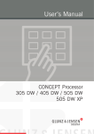
Finding a spare part
1
5-2
2
Spare parts
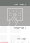
Thickness gauge table
Spare parts
Thickness gauge table
5-3
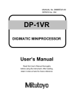
Thickness gauge table
1
Pos. No
2
Part No
Specification
4
3
4
2
4
6
4
5
8
7
11
9
11
1
M-5-GA-003
INSTRUMENT, MEASURING
2
M-5-AA-055
SPACER, D16 x 22
3
2-366-012
4
M-5-BA-033
5
2-366-013
6
2-366-023
WHEEL, PEBBLE
7
5-DF-009
SPRING, SHORT
8
2-366-003
9
5-DF-029
10
2-366-024
SPINDLE
BEARING, BALL, D5 x 16
BASE, MEASURING
FORK
SPRING, LONG
SHAFT, WIRE, STEEL
11
5-BA-003
12
2-366-014
SHAFT, ARM, PEDAL
13
2-366-016
ARM, PEDAL, LEFT
BEARING, BALL, D10 x 30
14
1-366-001
BAR, PEDAL
15
2-366-015
ARM, PEDAL, RIGHT
16
12
17
10
18
19
15
20
21
13
12
11
22
14
23
11
24
25
26
27
28
THICKNESS GAUGE TABLE
29
30
T80088
User's Manual - CONCEPT 500 TGT
1437
1437
User's Manual - CONCEPT 500 TGT
1. Find the specific part and the part’s Pos. No on the drawing.
2. Refer to the list on the opposite page to find the spare part’s number and specification.
1437
User's Manual - CONCEPT 500 TGT
5-1
5-2
Spare parts
Thickness gauge table
1
2
4
3
4
2
4
6
4
5
8
7
11
9
11
12
10
15
13
12
11
14
11
THICKNESS GAUGE TABLE
T80088
User's Manual - CONCEPT 500 TGT
1437
Spare parts
Thickness gauge table
Thickness gauge table
Pos. No
Part No
Specification
1
M-5-GA-003
INSTRUMENT, MEASURING
2
M-5-AA-055
SPACER, D16 x 22
3
2-366-012
4
M-5-BA-033
5
2-366-013
BASE, MEASURING
6
2-366-023
WHEEL, PEBBLE
7
5-DF-009
SPRING, SHORT
8
2-366-003
9
5-DF-029
10
2-366-024
11
5-BA-003
12
2-366-014
SHAFT, ARM, PEDAL
13
2-366-016
ARM, PEDAL, LEFT
14
1-366-001
BAR, PEDAL
15
2-366-015
ARM, PEDAL, RIGHT
SPINDLE
BEARING, BALL, D5 x 16
FORK
SPRING, LONG
SHAFT, WIRE, STEEL
BEARING, BALL, D10 x 30
16
17
18
19
20
21
22
23
24
25
26
27
28
29
30
1437
User's Manual - CONCEPT 500 TGT
5-3
5-4
Spare parts
Thickness gauge table
User's Manual - CONCEPT 500 TGT
1437