1
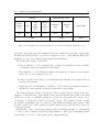
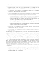
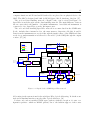
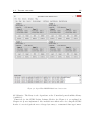
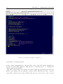
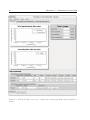
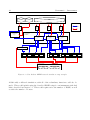
6.1. Systems demonstration simulation
45
MultiControl software (see Chapter 4.1) was used. Each EGSE was loaded with a variation of the baseline script, with variables such as SpaceWire address, used process IDs
(PIDs) and data generation rates customized.
Two instances of the developed PUS Node software were used. These simulated some of
the SSMM and OBC functions. The first was configured to act as the input ports and
the Write Module of the SSMM. This included configuring the four SpaceWire interfaces
in two groups, one for each input router. The first PUS Node instance included the
possibility to send telecommands, but this feature was disabled as it was not of interest.
The OBC functions were simulated in another instance of the PUS Node software. In
this instance, the telecommand generation widget was enabled and customised for the
simulation need.
The router configuration was made through the Device Configuration tool included in
STAR-System.
The housekeeping and scientific data transfer data rates from the instruments were set to
emulate expected data rates for a deep-space mission, like the ones described in Chapter
3. The housekeeping data was set to always be on, from as soon as the EGSE were
started. The scientific data generation was set to two different rates per instruments or
completely off. Telecommands from the OBC simulator determined what data rates were
to be used at what times.
The housekeeping data as well as event reports was routed directly to the OBC. and
all scientific data, directly to the SSMM simulator. Telecommand could be routed from
the OBC to any of the instruments.
The router configuration used in the simulation can be seen in Table 6.1. The SSMM
was addressed using one logical address per node it would be receiving from, using the
logical address values 32-39. This was done to emulate the behavior of the SSMM device
described in Chapter 3. The address range was chosen as it starts on the lowest value
allowed for SpaceWire logical address (lower addresses are used for path addressing).
Each instrument was given a unique SpaceWire logical address, with a value between 64
and 71 and the OBC was given 128.
The simulation made use of the split of the APID field into a PID (process ID) and
PCAT (packet category).
Each instrument was given two PID: one for control and monitoring and one for science
data. The control and monitoring PID was responsible for all housekeeping data, event
reports and receiving telecommands. The second PID was used for all science data
generation. This was done to emulate an instrument which separates its control function
from its detectors - as described in Chapter 5.
An alternative setup where multiple PIDs for science data per instrument was also