1
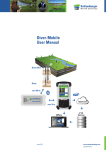
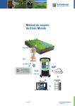
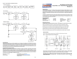
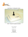
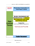
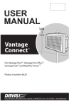
Diver-NETZ
User Manual
Traditional
data collection
Diver-DXT
Diver-DXT cable
Diver
FTP
Server
GPRS
Radio
Internet
Status
Bluetooth
TM
Charge
Diver-Gate (M)
Office
June 2012
Office
www.swstechnology.com
copyright of SLB
Version June 2012
All rights reserved. No part of this publication may be duplicated, stored in a
computerized data file or made public in any form or manner whatsoever,
be it electronic, mechanical, in photocopies, recordings or in any other way,
without prior written permission from
Schlumberger Water Services (Netherlands) BV
Schlumberger Water Services
Delftechpark 20
PO Box 553
2600 AN Delft
The Netherlands
Tel.: +31 (0)15 275 5000
www.swstechnology.com
June 2012
www.swstechnology.com
copyright of SLB
WARNING TO USERS IN THE UNITED STATES
Federal Communication Commission Interference
Statement 47 CFR Section 15.105(b)
This equipment has been tested and found to comply with the limits for a Class B
digital device, pursuant to Part 15 of the FCC Rules. These limits are designed to
provide reasonable protection against harmful interference in a residential installation. This equipment generates, uses and can radiate radio frequency energy and,
if not installed and used in accordance with the instructions, may cause harmful
interference to radio communications. However, there is no guarantee that interference will not occur in a particular installation. If this equipment does cause harmful
interference to radio or television reception, which can be determined by turning the
equipment off and on, the user is encouraged to try to correct the interference by
one of the following measures:
- Reorient or relocate the receiving antenna.
- Increase the separation between the equipment and receiver.
- Connect the equipment to an outlet on a circuit different from that to which the receiver is connected.
- Consult the dealer or an experienced radio/TV technician for help.
This device (Diver-DXT) complies with Part 15 of the FCC Rules. Operation is subject
to the following two conditions: (1) This device may not cause harmful interference,
and (2) this device must accept any interference received, including interference
that may cause undesired operation.
NO UNAUTHORIZED MODIFICATIONS
47 CFR Section 15.21
CAUTION:
This equipment may not be modified, altered or changed in any way without signed written permission from Schlumberger Water Services (Netherlands) BV.
Unauthorized modification may void the equipment authorization from the FCC and
will void the Schlumberger Water Services (Netherlands) BV warranty.
FCC and IC RF Radiation Exposure Statement:
This device complies with FCC and Industry Canada RF radiation exposure limits set
forth for the general population (uncontrolled exposure). This device must be installed to provide a separation distance of at least 20 cm from all persons and must not
be collocated or operating in conjunction with any other antenna or transmitter.
June 2012
www.swstechnology.com
copyright of SLB
IC REQUIREMENTS FOR CANADA
This class B digital apparatus meets all requirements of the Canadian Interferencecausing equipment regulations.
Cet appareil numérique de la classe B respecte toutes les exigences du règlement
sur le matériel brouilleur du Canada.
This device complies with Industry Canada licence-exempt RSS standard(s).
Operation is subject to the following two conditions: (1) this device may not cause
interference, and (2) this device must accept any interference, including interference that may cause undesired operation of the device.
Le présent appareil est conforme aux CNR d’Industrie Canada applicables aux
appareils radio exempts de licence. L’exploitation est autorisée aux deux conditions
suivantes: (1) il ne doit pas produire de brouillage, et (2) l’utilisateur du dispositif doit
être prêt a accepter tout brouillage radioélectrique reçu, même si ce brouillage est
susceptible de compromettre le fonctionnement du dispositif.
CE COMPLIANCE STATEMENT (EUROPE)
This device is in conformity with the EMC directive and low-voltage directive.
June 2012
www.swstechnology.com
copyright of SLB
Table of Contents
Introduction1
Diver-NETZ components
2
Diver dataloggers
2
Diver-DXT cable
2
Diver-DXT2
Diver-Gate(M)3
Diver-NETZ software
3
Before you go into the field
4
Charging the Diver-Gate(M) battery
4
Bluetooth pairing of the Diver-Gate(M) with a mobile device 4
Setting up a USB connection between the Diver-Gate(M) and a PC 6
Installation of the Diver-DXT
10
Adjusting the cable length
10
Installation in a well with a synthetic flush mounted well cover 11
Installation in a well with a synthetic protective cover
11
Installation in a well with a metal protective cover
12
Maintenance13
Maintenance of Diver-DXT
June 2012
13
www.swstechnology.com
copyright of SLB
Appendices
Appendix I
FAQ Diver-NETZ
Appendix II
Diver-DXT cable technical specifications
Appendix III
Diver-DXT technical specifications
Appendix IV
Diver-Gate(M) technical specifications
June 2012
www.swstechnology.com
copyright of SLB
Introduction
With Diver-NETZ technology, monitoring of ground and surface water becomes
easier, faster and more reliable. Diver-NETZ is a wireless method for reading out
Diver data and programming Divers. A physical connection between read-out
equipment and the Diver is no longer necessary.
With Diver-NETZ it is not necessary to find the monitoring well, the monitoring well
finds you. A functional description of Diver-NETZ technology is presented in the diagram below. The monitoring well (with Diver-DXT installed) periodically tries to connect to a Diver-Gate(M) available within its radio range. This Diver-Gate(M) is connected to a mobile device (smartphone ,PDA or PC) using Bluetooth or a USB cable
(only for PC). As soon as you have read out Diver data with a mobile device, you can
transfer the data to a FTP server or keep it in the local queue. All data will be stored
in the database of the device. Programs like Diver-Office and Diver-Office Premium
are used to interpret, validate or visualize the Diver data.
Any existing network of Divers can be quickly and easily fitted with the Diver-NETZ
technology.
FTP
Server
GPRS
Radio
Internet
Status
Bluetooth
TM
Charge
Diver-Gate (M)
Office
Office
Page |
June 2012
1
www.swstechnology.com
copyright of SLB
Diver-NETZ components
The components of the Diver-NETZ system are:
• Diver datalogger(s)
• Diver-DXT cable
•Diver-DXT
•Diver-Gate(M)
• Diver-NETZ software applications
(Diver-Mobile, Diver-Pocket or Diver-Office)
Additional components of Diver-NETZ are:
• plastic protective cap available in 2 models:
•for 1 Diver-DXT
•for up to 4 Diver-DXT
• cable adaptors for fitting / shortening the cable
Diver dataloggers
Diver dataloggers are cost-effective and reliable instruments to provide long-term,
frequent measurements of water levels, temperature and conductivity. Divers are
ideal for monitoring municipal water supplies, salt water intrusion, brine storage and
migration, and environmental monitoring of contamination and remediation projects.
For more information on Diver dataloggers see the Diver Product Manual.
Diver-DXT cable
The Diver-DXT cable is used to connect a Diver to the Diver-DXT. The Diver-DXT
cable is mounted into the Diver-DXT housing using a heavy-duty, water-tight connector that allows you to adjust the cable length as needed. This cable is available
in different lengths (up to 300 meters). For more information see Appendix II.
Diver-DXT
The Diver-DXT makes wireless communication possible. The water-resistant housing contains a datalogger for recording barometric pressure and temperature.
Furthermore, the Diver-DXT contains a battery and a radio module.
The Diver-DXT is placed on top of a well, while the Diver is placed inside a well
below groundwater level. Both units are connected using a two-wire Diver-DXT
cable, which acts as a communication link and a mechanical link.
The Diver-DXT is not meant to be used under water. The radio performance will
decrease when the unit is covered or surrounded by water. However, sometimes it
is difficult to avoid flooding conditions. Therefore the Diver-DXT has been developed
to withstand this situation for a limited time (maximum of one meter water pressure
for a duration of two days). For more information about Diver-DXT specifications,
see Appendix III.
Page |
June 2012
2
www.swstechnology.com
copyright of SLB
Diver-Gate(M)
The portable Diver-Gate(M) provides the communication between the Diver-DXT
and the mobile device via a Bluetooth connection. The Diver-Gate(M) contains a
radio module to communicate with the Diver-DXT. The unit also contains a Bluetooth
radio for communication with a mobile device or PC. The Diver-Gate(M) works with
an internal rechargeable lithium ion battery. There are four light-emitting diode (LED)
indicators to indicate the charge status, the status of the radios (Bluetooth and the
Diver-DXT radio) and the general operating status.
• Radio LED:
• Blinking: indicates scanning for Diver-DXTs
• Continuously on: indicates data exchange between the Diver-Gate(M) and the Diver-DXT
• Status LED:
• Blinking: indicates operation mode
• Continuously on: indicates (re)booting of the Diver-Gate(M)
• Bluetooth LED:
• Blinking (short on and long off): indicates making a connection or pairing with a mobile device
• Fast blinking (almost continuously on): indicates Bluetooth connection mode
• Charge LED:
• On: indicates charging
• Off: indicates no charging or the battery is charged
To communicate with the Diver-DXT the Diver-Gate(M) is carried into the field to a
position within radio range of the Diver-DXT. To protect the Diver-Gate(M) against
environmental conditions a rubber protection guard is provided. Diver-Gate(M)
technical specifications can be found in Appendix IV.
Diver-NETZ software
There are different software applications available, which can be used to
communicate with the Diver-NETZ components:
• Diver-Mobile: is a user-friendly mobile device application (Windows Mobile) to read out the data from dataloggers in the field.
• Diver-Pocket: is a comprehensive mobile device application (Windows Mobile) to read out and configure dataloggers (when 2012 version is available).
• Diver-Office: is a comprehensive PC application (Windows) to read out, configure and manage dataloggers.
For more information about Diver-Mobile see the Diver-Mobile User Manual on the
www.swstechnology.com website.
Page |
June 2012
3
www.swstechnology.com
copyright of SLB
Before you go into the field
Before going into the field, the user needs to make sure the following steps are
undertaken:
• Charging the battery of the Diver-Gate(M)
• Connecting the Diver-Gate(M) with a mobile device
•Bluetooth pairing of the Diver-Gate(M) with a smartphone or PDA
•Or setting up a USB connection between the Diver-Gate(M) and a PC
Charging the Diver-Gate(M) battery
When charging the Diver-Gate(M) for the first time it is necessary to use a USB
charger (not provided) and not to charge using a laptop or PC. The Diver-Gate(M)
needs to be turned ON while the charger is connected. Leave it ON until fully
charged, indicated by the Charge LED turning off (approximately 5 hours). This procedure also needs to be performed if the device has not been used for more than
two weeks.
If the Diver-Gate(M) is used on a regular basis the device can be charged using any
USB port (PC, car USB charge, etc.). In this case the Diver-Gate(M) can be turned
off while charging.
It is also possible to charge the Diver-Gate(M) continuously. Using the Bluetooth
functionality of the Diver-Gate(M) while continuously charging is only possible with
a USB charger and not with a USB port.
Bluetooth pairing of the Diver-Gate(M) with a mobile device
When the Diver-Gate(M) is used in combination with a mobile device and DiverMobile software, the radio link between the Diver-Gate(M) and the mobile device is
based on a Bluetooth link. To enable the Bluetooth connection, the following steps
illustrate how to pair a Diver-Gate(M) with a mobile device.
• Attach the pairing dongle to the Diver-Gate(M).
• Turn on the Diver-Gate(M).
• Activate the Bluetooth function on a mobile device (usually found under the Settings menu) and set it to be discoverable or visible to other devices.
• Open the Bluetooth connection settings and start searching for nearby Bluetooth devices.
• Remove the pairing dongle.
• After retrieving a list of nearby Bluetooth devices, select the Diver-Gate(M) (name is SWSGW_1414xxxxxxxx) (see example figure 1) and press Next.
• Enter passcode “1234” and press OK (see example figure 2).
• After the passcode is accepted, the name of the Diver-Gate(M) is displayed under disconnected devices (see example figure 3).
• Select Diver-Gate(M) to modify its settings.
• Activate “Serial port” (see example figure 4).
• The Diver-Gate(M) will automatically restart (Status LED will be continuously on for 5 to 10 seconds).
• After approximately 30 seconds the Bluetooth LED will turn on to indicate a Bluetooth connection.
Page |
June 2012
4
www.swstechnology.com
copyright of SLB
Figure 1: Search for Diver-Gate(M)
Figure 2: Enter passcode
Figure 3: Select and modify device
Figure 4: Activate Serial Port
Pairing between the Diver-Gate(M) and a PC is similar to the steps described above.
Once the devices have been paired, the Diver-Gate(M) will automatically connect to
the particular device when turned on the next time. The Diver-Gate(M) can only be
paired with one other device.
Page |
June 2012
5
www.swstechnology.com
copyright of SLB
Setting up a USB connection between the Diver-Gate(M) and a PC
When the Diver-Gate(M) is used in combination with a PC and Diver-Office 2012
software, the link between the Diver-Gate(M) and the PC is based on a
USB connection. As an example, the following steps illustrate how to enable
a USB connection between the Diver-Gate(M) and a Windows XP PC.
When getting information that new hardware has been found, open the
Found New Hardware Wizard and:
1.Choose the option to connect to Windows Update to search for software and
click Next.
2.Select the option to install software from a list or specific location and click Next.
Page |
June 2012
6
www.swstechnology.com
copyright of SLB
3.Choose the option to select the device from a list and click Next.
4.Click Have Disk option.
5.Click Browse option.
Page |
June 2012
7
www.swstechnology.com
copyright of SLB
6.Browse for gserial.inf. This file can be downloaded from the
www.swstechnology.com website. Click Open.
7.Click OK.
8.Select Next to continue.
Page |
June 2012
8
www.swstechnology.com
copyright of SLB
9.Click the Continue Anyway button.
10.Click Finish. The software is successfully installed.
For additional information about setting up a USB connection between the DiverGate(M) and a PC, please have a look at the ‘Diver-Office Installation Guide-DiverGate(M) driver installation’ on the www.swstechnology.com website.
Page |
June 2012
9
www.swstechnology.com
copyright of SLB
Installation of the Diver-DXT
The Diver-DXT is a radio module with a built-in datalogger for barometric pressure.
Together with a built-in battery the Diver-DXT will operate independently from the
connected equipment. However, the system will only be functional if a Diver-DXT
cable and Diver are connected. The complete equipment for the well is:
• Diver datalogger (see supported Diver datalogger list).
• Diver-DXT cable to connect the Diver to the Diver-DXT.
• The Diver-DXT (which is placed on top of the well or outside the well protection).
Adjusting the cable length
It is important to determine the proper cable length for the Diver for the following
reasons:
• If the cable length is too short:
•the Diver will be located above the water level. This will not damage the Diver, but the Diver will no longer record water levels.
• If the cable length is too long:
•the Diver can be subjected to excessive pressure from the water column on top of the Diver. This can harm the Diver and the Diver will no longer record water levels.
•the Diver can end up at the bottom of the well and this can affect the reliability
of the Diver data.
It is important to know the highest and the lowest expected water levels from the
top of casing (TOC). The difference between the highest and lowest water levels
is important to define the pressure range of the Diver and the length of Diver-DXT
cable.
There are two methods to adjust the cable length:
• Integrated Diver-DXT cable length adjustment. This method is used if the
Diver-DXT is placed on the TOC.
• With a cable adaptor. This method is used if the Diver-DXT is placed on top of the well protection cover. In this situation the cable adaptor is placed on top of
the casing
Effective working length of the cable
The next paragraphs illustrate how to install the Diver-DXT in the following
situations:
• installation in a well with a synthetic flush mounted well cover
• installation in a well with a synthetic protective cover
• installation in a well with a metal protective cover
Page |
June 2012
10
www.swstechnology.com
copyright of SLB
Installation in a well with a synthetic flush mounted well cover
Flush mounted well covers are often used in an urban environment. Most of these
flush mounted well covers are made of synthetic materials which allow the use of
radios (such as the Diver-DXT). Metal flush mounted well covers, however, are not
suitable for use in combination with the Diver-DXT.
The Diver-DXT is placed on top of the casing. The space from the top of the casing
to the bottom of the synthetic protection cover needs to be at least 30 mm. If the
location has more than one casing it is possible to use more Diver-DXTs. In this
case there will be no interference between the Diver-DXTs. For radio performance it
is important to have the Diver-DXT placed as closely as possible to the cover of the
flush mounted well. The radio performance will decrease if the distance between
the Diver-DXT and the ground surface increases.
Instrumentation is not visible when the cover is closed and it is therefore protected
against vandalism.
When the Diver-DXT is ready to be installed in a well the next action points are
needed:
• Take a manual water level measurement from the TOC before the Diver-DXT with the Diver is lowered into the well.
• Measure the distance between the membrane of the Diver and the bottom of the Diver-DXT radio unit (= cable length).
Effective working length of the cable (Baro-, Cera-, Mini- en Micro-Diver)
• Place the Diver-DXT with the cable and Diver connected to it in the well.
Installation in well with synthetic protective cover
Most wells consist of a protective cover above ground level. Some of these
protective covers are made of metal while others are made of a synthetic material.
The installation of the Diver-DXT in a synthetic protection cover is similar to the
installation in a flush mounted well cover. The Diver-DXT is placed on top of the
casing. The space from the top of the casing to the bottom of the synthetic protective cover needs to be at least 30 mm. If the location has more than one casing it is
possible to use more Diver-DXTs. In this case there will be no interference between
the Diver-DXTs. The protective cover and lockable cap/cover will secure the
installation against vandalism. Instrumentation is not visible when the cap is closed.
When the Diver-DXT is ready to be installed in a well the next action points are
needed:
• Take a manual water level measurement from the TOC before the Diver-DXT with the Diver is lowered into the well.
• Measure the distance between the membrane of the Diver and the bottom of the Diver-DXT radio unit (= cable length).
Page |
June 2012
11
www.swstechnology.com
copyright of SLB
Effective working length of the cable (Baro-, Cera-, Mini- en Micro-Diver)
• Place the Diver-DXT with the cable and Diver connected to it in the well.
Installation in a well with a metal protective cover
Most wells consist of a protective cover above ground level. Some of these protective covers are made of metal while others are made of a synthetic material. Because
the Diver-DXT cannot be used inside a metal enclosure an alternative installation is
needed.
The Diver-DXT cannot be placed inside the metal enclosure because of the shielding of radio signals. Therefore the Diver-DXT has to be placed outside the metal
protective cover. This can be done by drilling holes in the cap and placing the DiverDXT on top of the cover. It is also possible to place more than one Diver-DXT on top
of the protective cover. A drilling stencil is available for drilling the required holes.
An extra sturdy protective cover is available to protect the Diver-DXT against
vandalism.
When the Diver-DXT is ready to be installed in a well the next action points are
needed:
• Take a manual water level measurement from the TOC before the Diver-DXT with the Diver is lowered into the well.
• Measure the distance between the membrane of the Diver and the cable adaptor (= cable length).
Effective working length of the cable
• Place the Diver-DXT with the cable and Diver connected to it in the well.
Page |
June 2012
12
www.swstechnology.com
copyright of SLB
Maintenance
Maintenance of Diver-DXT
The Diver-DXT has a built-in datalogger for the barometric pressure and ambient
temperature. The sensor is located under the upper part of the Diver-DXT (see figure
below). This sensor should be in open contact with the air pressure. Maintenance is
needed to keep the area around the location of the sensor clean. Extreme high and
low temperatures, mud, moisture or water could affect the accuracy of the sensor.
Clogging of the sensor opening can result in sensor drift/deviation.
Page |
June 2012
13
www.swstechnology.com
copyright of SLB
Appendices
June 2012
www.swstechnology.com
copyright of SLB
Appendix I
June 2012
www.swstechnology.com
copyright of SLB
FAQ Diver-NETZ
How do I store and handle the equipment?
Before installation, the equipment should be stored in a safe place. However, it is
important to know what the effects of storage are for the instrument. The Diver-DXT
has a built-in battery which cannot be switched off. This means that the instrument
is always active and consumes energy from the battery. The total battery capacity
will be reduced by approximately 4% per year in storage conditions.
Another important storage condition is the ambient temperature. If the instrument is
stored for a long period of time (more than one month) it is best to store the instrument in a dark place at room temperature.
HANDLE
WITH CARE
The instrument is tested for transport conditions according to ASTM D 4169-09 DC
2 (transport simulation test). This globally accepted standard ensures no damage
if the instrument is transported under normal conditions in its own packaging.
Keep the instrument in the original packaging until it is installed in the field. The
instrument is also tested according to MIL-STD-810 and ASTM D 3332 (shock and
vibration tests). This test simulates the mechanical shocks and vibrations during
installation of the Diver-DXT. Although the equipment can handle these conditions, it
is better to avoid any abnormal shocks and vibrations if possible. The Diver-DXT has
sensors which need to be handled with care.
How does Diver-NETZ work?
The figure below depicts the setup of the Diver-NETZ. From left to right: The Diver
is suspended on a Diver-DXT cable with on top the Diver-DXT. The Diver-DXT sends
information (data) wirelessly to the Diver-Gate(M). The Diver-Gate(M) can be
wirelessly connected through Bluetooth to a Windows Mobile based device.
On this device the Diver-Mobile application needs to be installed to communicate
with the Diver. The Diver-Mobile application will store the Diver data and can
optionally send the data to a FTP server.
FTP
Server
GPRS
Radio
Internet
Status
Bluetooth
TM
Charge
Diver-Gate (M)
Office
June 2012
Office
www.swstechnology.com
copyright of SLB
What is the radio range between the Diver-Gate(M) and the Diver-DXT?
The radio technology of the Diver-DXT and the Diver-Gate(M) makes use of the ISM
(Industrial, Scientific and Medical) band. Specifically, the 2.4 GHz radio frequency
is used. This radio band is unlicensed, which means that the frequencies are open
for public use and require no registration or payment for usage of the frequency. In
order to comply with the regulations, the output power of the devices is regulated.
This regulation may cause limited range of the radio device. Typically, the radio
range of the Diver-DXT device is about 500 meters (1,300 ft) line-of-sight (LOS).
Certain characteristics inherent to the environment where the system is deployed
may affect the range of the radio system. This includes, but is not limited to, rain,
snow, fog, large bodies of water, trees, forests, metal well protective covers, buildings, atmospheric conditions, ambient frequencies, noise, electromagnetic fields
and general conditions of the terrain. Besides, the positioning of the Diver-DXT may
affect the range of the radio system as well.
To maximize the performance of the radio devices, it is recommended to place the
Diver-DXT in an area where it is possible to “see” the device without obstacles in
between. This is not mandatory, but improves the performance of the system. If this
condition is not met, the performance of the system may be reduced. We therefore
recommend a site assessment in order to plan and optimize the deployment of
devices.
What do I need to know about Bluetooth?
Bluetooth is a simple two-way wireless radio technology that allows different
devices to connect between each other without the use of cables or infrared waves.
This technology is robust, low-power and low-cost. The short range radio link
provides connectivity between different devices, such as mobile phones, PDAs,
PCs and other electronic devices. It is designed to be used in small range
communication and allows voice and data communication. It operates in the
2.4 GHz radio spectrum. Each class provides a different power output and they
have different communication ranges. This is certified in three different types of
standard: Class 1 (100 meters), Class 2 (10 meter), Class 3 (1 meter).
The Diver-Gate(M) has a Class 2 (10 meter) Bluetooth module.
Can I use a mobile phone?
Yes, mobile phones with the following specifications can be used for Diver-NETZ:
• Windows Mobile version 6.1 and higher
• Minimum of 4 GB of Flash memory (SD card)
• Minimum of 128 MB of RAM
• Bluetooth version 2.0 and later
• Data-plan: if you want to send the data to a FTP server
June 2012
www.swstechnology.com
copyright of SLB
Can I use a Pocket-PC?
Yes, Pocket-PCs with the following specifications can be used for Diver-NETZ:
• Windows Mobile version 6.1 and higher
• Minimum of 4 GB of Flash memory (SD card)
• Minimum of 128 MB of RAM
• Bluetooth version 2.0 and later
• GSM/GPRS option and a dataplan if you want to send the data to a FTP server
Can I use a laptop?
Yes, you can use a laptop with Diver-Office 2012.1. The following hard- and software
requirements are needed to install Diver-Office 2012.1:
• Operating system: Windows XP (SP2 or later, 32 & 64-bit), Windows Vista Business
(32 & 64-bit) or Windows 7 Professional (32 & 64-bit)
• Processor: Pentium 4-compatible processor or higher, 1.6 GHz or higher
recommended
• Hard Disk: 2GB (3GB or more recommended)
• Memory: 1GB RAM (2GB or more recommended)
• Serial communication: One available USB port or one Serial COM port
• Screen resolution: 1024 x 768, color: 16 bits
• Microsoft SQL Server Compact Edition 3.5 SP2 (included in installation package)
In what languages is Diver-Mobile available?
The Diver-Mobile application is available in the English language.
Can I use my own FTP server?
Yes. In the Diver-Mobile application you can set the address of the FTP server.
What are the requirements for a FTP server?
The FTP server must be a standard none secured FTP server.
Can I use my existing Diver Data Cables?
Yes, you can use your existing DDC cables. However, the connector of the DDC
cable needs to be modified by SWS.
What is the maximum cable length that can be used?
The maximum cable length is 300 meters.
How long does the battery in the Diver-DXT last?
The nominal battery lifespan is 5 years. The battery can be replaced SWS.
What are the max/min operating temperatures of the Diver-DXT?
The Diver-DXT operating temperature range is from -20 °C up to +80 °C. The battery
life time will decrease when the device is used below 0°C and/or above 40°C.
How much water can be on top of the Diver-DXT?
The Diver-DXT is designed to withstand 1 meter water pressure for 2 days.
Please note that the barometric sensor will not measure the barometric
pressure while immersed in water.
June 2012
www.swstechnology.com
copyright of SLB
Is the old Diver-DXT compatible with the new Diver-DXT?
No, the new Diver-DXT is not compatible with the old Diver-DXT (produced until 2009).
Can I download the barometric data when the Diver-DXT fails?
No. The Diver-DXT must be returned to SWS. In most cases SWS can retrieve your
data from the Diver-DXT.
How long does the battery in the Diver-Gate(M) last and how can it be recharged?
The battery in the Diver-Gate(M) can be used for 10 hours without the need for
recharging. The Diver-Gate(M) is recharged through the USB port on the DiverGate(M).
I fully charged the battery but when I turn on the Diver-Gate(M) all the LEDs go off
after a few seconds?
When a Diver-Gate(M) with fully charged battery turns off or if you unplug and plug
the internal battery, it is necessary to follow the following procedure:
• Connect the USB cable to the Diver-Gate(M)
• Switch on the Diver-Gate(M)
• The status LED should start blinking for at least 30 seconds
• After several minutes the battery level is calibrated with the battery. You can leave the device on during charging
Can I start/stop/reprogram a Diver with Diver-NETZ?
Yes, this can be done with Diver-Office 2012.1 and Diver-Pocket
(when version 2012 is available).
Can other people connect with Diver-NETZ to my Divers?
The Diver-DXT and the Diver-Gate(M) can be protected by a Network-ID.
What to do when you get an error while starting Diver-Mobile?
If the Diver-Mobile application generates the following error “No Diver-Gate(M)
found”, there is no Bluetooth connection between the Diver-Gate(M) and a mobile
device. See FAQ “I do not have a Bluetooth connection between the Diver-Gate(M)
and the mobile device”.
I do not have a Bluetooth connection Between the Diver-Gate(M) and the Mobile
Device?
Please follow the next steps:
• Check the Bluetooth LED of the Diver-Gate(M). This LED should blinking fast (almost continuously on)
• If the Bluetooth LED doesn’t blink at all (not even for a short period) the
Diver-Gate(M) has to be paired. Follow the Bluetooth pairing procedure
• If the Bluetooth LED does blink but will not go into an almost continuous mode (indicating the Bluetooth connection), the Bluetooth of the mobile device is not visible to the Diver-Gate(M). Change the Bluetooth settings of the mobile device to “Always Visible”
• If the Bluetooth LED indicates a Bluetooth connection but the application cannot find the Diver-Gate(M) it is possible that the serial port check box in the Bluetooth settings is not ticked. Tick this box (enable serial port) and try again.
June 2012
www.swstechnology.com
copyright of SLB
I don’t have Bluetooth connection between the Diver-Gate(M) and a mobile device
anymore but it worked in the past?
Check if Bluetooth is enabled. Check the Bluetooth status on your device
(PC, mobile device). Some devices also have a switch that shuts down all radios
(WiFi and Bluetooth). Make sure this switch is on.
I do not have a radio connection between the Diver-Gate(M) and the Diver-DXTs?
Please follow the next steps:
• If you have no connection after 30 seconds you may be out of radio range. Try to move closer to the Diver-DXT and re-establish the connection. Try this a few times from different locations.
• From 07:00 PM to 07:00 AM the radio of the Diver-DXT will be in sleep mode to save battery capacity. Making a connection can therefore take more time (longer than 5 minutes).
• Make sure you use the correct Network ID. For selecting the correct Network ID see the Diver-Mobile Manual.
• Check if the Radio LED on the Diver-Gate(M) is blinking during scanning and
continuously on during data transfer. If not, the problem could be the
Diver-Gate(M).
Diver-Mobile is unresponsive. What should I do?
Go to Task Manager and shut down the Diver-Mobile application or give your field
device a soft reset. How to do this is described in the user manual of the field
device.
June 2012
www.swstechnology.com
copyright of SLB
Appendix II
June 2012
www.swstechnology.com
copyright of SLB
Technical Specifications
Diver-DXT cable
Article number
Ingress protection
Length accuracy Cable stretch Maximum length
Cable length adjustment
Temperature range Material of connectors Material of cable jacket
AS2xxx.x*
IP68**
±1% (≥1 cm)
<1%
300 m
up to 40% of maximum length
-20°C to 80°C
nylon PA6, fibreglass-reinforced (30%)
polyurethane (PU)
Cable length according to customer specifications.
* AS2xxx.x (xxx.x is length in meters). Example: AS2015 is 15 m and AS2001.5 is 1.5 m.
** Only if connected to Diver-DXT.
June 2012
105 mm
D = 23.3 mm
110 mm
D = 22 mm
Specific length of the cable
D = 3.2 mm
97 mm
Effective working length of the cable (Baro-, Cera-, Mini- en Micro-Diver)
D = 49 mm
D = 18 mm
44 mm
89 mm
Specific length of the cable
Effective working length of the cable (CTD-Diver)
28.5 mm
Diver-DXT dimensions
www.swstechnology.com
copyright of SLB
Appendix III
June 2012
www.swstechnology.com
copyright of SLB
Technical Specifications
Diver-DXT
General
Diameter
Ø 49-23 mm
Length
141 mm (including chassis connector)
Weight
84 g
Housing material
High Heat ABS Polylac® casing, Viton® and MBR o-rings, Cu Zn/Ni connector
ProtectionIP68
Operating temperature (OT)
-20°C to 60°C (within specs)
Maximum operating temperature (MOT) -20°C to 80°C (not guaranteed within specs)
Storage / transport temperature *
-40°C to 85°C
Battery life
5 years @ OT, depending on operation
and maximum 3,000 connections with Diver-Gate, 30,000 memory block reads (dataset if 84 bytes)
Battery
Non-rechargeable lithium-thionyl chloride (3600 mAh)
Battery replacement
By manufacturer
Instrument interface
Diver-DXT cable with Baro-Diver, Mini-
Diver, Micro-Diver, Cera-Diver and
CTD-Diver
Datalogger barometer
Storage capacity Measuring interval
Measuring method
Clock accuracy Recorded parameters
24,000 measurements
(non-volatile memory)
60 min
Fixed time based
Automatic synchronization with attached Diver (once a day)
Barometric pressure (cmH2O) and
temperature (°C)
Barosensor
Sensor Range Accuracy
Resolution Absolute maximum pressure (MP) Absolute maximum burst pressure Long-term stability Piezo-resistive silicon micro machined
sensor
400-1,150 cmH2O
±1 cmH2O (typical) ±2 cmH2O (maximum) @OT
0.1 cmH2O
1.5 bar (absolute)
2 bar (absolute) @1 sec
±1 cmH2O/year (typical) @OT
Temperature
Sensor Range Accuracy
Resolution Silicon temperature sensor
-20°C to 80°C
±1°C (typical) ±3°C (maximum) @OT
0.1°C
June 2012
www.swstechnology.com
copyright of SLB
Radio
Radio frequency (central frequency) Transmit power Scan-for-host period Radio range Data encryption 2.405 GHz (channel 11)
100 mW, 20 dBm
14 seconds (7:00AM-7:00PM),
300 seconds (7:00PM-7:00AM)
500 m LOS (Line-of-sight)
AES key (16 bytes)
Environment
Operating temperature Operating elevation range
Pressure Random vibration Mechanical shock Transportation
Certification
-20°C to 60°C (within specs)
-300 to 5,000 m MSL (mean sea level)
Up to MP (in air)
MIL-STD-810: 10 Hz 0.02 g2/Hz, 60-1,000 Hz
0.02 g2/Hz, 1,000-2,000 Hz 6 dB/oct
ASTM D 3332: Free-fall drop 0.1 to 0.7 m
(500 g @ 2 ms)
According to ASTM D 4169-08, DC2 (out
side of western Europe by lorry/air/boat)
CE: R&TTE Directive 1999/5/EC according to the harmonized standards
FCC ID: V43DIVERDXT2
IC: 7675A-DIVERDXT2
*The Diver-DXT is always active. The leakage current of internal battery mostly
depends on the temperature. If stored or transported for a longer period of time at
elevated temperatures, the battery life time will be affected.
June 2012
www.swstechnology.com
copyright of SLB
Appendix IV
June 2012
www.swstechnology.com
copyright of SLB
Technical Specifications
Diver-Gate(M)
General
Dimensions
Weight
Housing material
Protection
Operating temperature
Storage / transport temperature
Power supply
Battery life
Communication
138 x 62 x 34 mm (with protection guard)
181 g
ABS casing
IP52 (with protection guard)
-20°C to 60°C (within specs)
-40°C to 85°C
Internal rechargeable lithium ion battery, charged through USB port
10 hours (typ) in Bluetooth connection mode
USB port, Bluetooth®
Bluetooth
Module
Antenna
Fully qualified Bluetooth® V2.1 + EDR, Class 2
Internal ceramic antenna
Radio
Radio frequency (central frequency)
Transmit power
Antenna
Scan period
Radio range
Data encryption
2.405 GHz (channel 11)
100 mW, 20 dBm
Internal ceramic antenna
30 seconds
500 m LOS (Line-of-sight)
AES key (16 bytes)
Environment
Operating temperature
Certification
-20°C to 60°C
CE: R&TTE Directive 1999/5/EC according to the harmonized standards
FCC: RI7BG864
IC: 5131A-BG864
June 2012
www.swstechnology.com
copyright of SLB