1
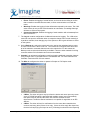
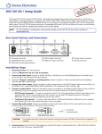
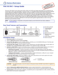
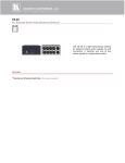
Product – ADC v11 and v12 Topic: Evertz 1200 Series 12x2 Routing Switchers This document describes the setup and use of the Evertz 1200 series routers in the ADC-100 environment. The modified GVG TEN-XL ASCII command protocol is used to control the Evertz 1200 series routers. There are some hardware differences between the 1200 series routers and the Grass Valley TEN-XL routers that have required differences in implementation of the protocol for the 1200 series routers. Since the GVG TEN-XL protocol is based on 10 input crosspoints and the Evertz 12 x 2 router family contains 12 input crosspoints, the protocol was extended to include crosspoint #11 and #12. Additionally, the 10XL protocol was originally designed to support an RS-485 bus containing a number of 10x1 switchers. While it is not recommended to connect devices to ADC-100 in an RS-485 configuration (there is no support for flow control on the Device Server), this driver supports the concept of addresses for the purpose of directing commands to one of the two destinations. Release Date: 18-August-2003 Revision History Revision Protocol Date Author Description 0.1 6-20-2003 D. Klochkov Initial Composition 0.2 8-12-2003 C. Kocsis Revision 1.0 8-18-03 B. Flemmons Final 1.1 5-13-15 Rebranded Version Used Model Tested: Evertz 1202S-AES 12x2 router Firmware: Version 1.1, build 125 Manual: Revision 1.3.2, Feb. 2003 Protocol: Grass Valley 10XL, using addresses as destinations, with extended Evertz proprietary support for inputs 11 and 12 © 2015 Imagine Communications Corp. Proprietary and Confidential 13-May-2015| Page 1 of 7 Requirements Device server version 9.8.4 or above is required with the Evertz 1200 device driver. Connections Using a standard straight-through serial cable, connect to the 9 pin female Remote port (Com 3) of the Evertz 1202S-AES and to the 9 pin female port on the serial card of the ADC Device Server. Consult the manufacturer’s manual for other 1200 series models. DB9 (male) Device Server Card DB9 (male) 1202 Router 2 (RX-) 2 (TX-) 3 (TX+) 3 (RX+) 7 (RX+) 7 (TX+) 8 (TX-) 8 (RX-) Device Set-up The Evertz 1202S-AES router requires internal configuration for RS-422 communication. Consult the manufacturer’s manual for other 1200 series models. On the 1202S-AES, remove the screws in the top cover to access the jumpers and ribbon cables. To configure the serial port for RS-422 communication: 1. Move the ribbon cable on J29 to J23. 2. Set the jumper on J26 to pins 2 and 3 (toward header J23). The firmware must be configured with the appropriate communications parameters. On the front panel of the 1202S-AES: 1. Press the Setup button and scroll down to REMOTE CTL. Press Select to enter the remote control menu. 2. Scroll until Baud Rate is displayed. Press Select to enter the Baud Rate menu. Scroll until you find 38400. Press Select again to activate the 38400 setting. Press Setup to back out to the Baud Rate menu. 3. Scroll down to Serial Format. Press Select to enter the Serial Format menu. Scroll until you find 8e1. Press Select again to activate 8e1. Press Setup to back out to the Serial Format menu. 4. Scroll down to Serial Address. Press Select to enter the Serial Address menu. Set this to the desired base address* for the low output of the router (the high output will be the © 2015 Imagine Communications Corp. Proprietary and Confidential 13-May-2015| Page 2 of 7 next consecutive number), and press Select. Press Setup to back out to the Serial Address menu. 5. Scroll down to Serial control. Press Select to enter the Serial control menu. Scroll until you find Slave. Press Select again to activate the Slave mode. Press Setup to back out to the Serial control menu. 6. Scroll down to Protocols. Press Select to enter the Protocols menu. Scroll until you find gvg ten xl ascii. Press Select to activate gvg ten xl ascii. Press Setup to back out to the Protocols menu. 7. Press Setup twice to back out to the EXIT menu and select Save and Exit. *IMPORTANT NOTE About the Base Address and Crosspoints: The ADC-100 driver supports base addresses for the router between 0 and 63. This makes the driver appear as a 12x64 router object, but the switcher will react to only two destination crosspoints: The base address crosspoint (for the first output) and the next consecutive number (the second output). Other commands with different destination crosspoints issued to the router will be ignored. Additionally, the Evertz router begins at address (destination #) zero, and ADC-100 is one-based. This means that a base address of 0 on the router is represented by destination 1 on ADC-100. If destinations 14 and 15 are configured on the ADC-100, for example, then the base address of the Evertz must be set to 13. Communications Parameters Add content about Comms. The communications parameters for this device are: Baud Rate: Data Bits: Stop Bits: Parity: Device Server Set-Up To configure the Evertz 1200 series router on the Device Server, you need access to the Device Server Configuration Utility: IMPORTANT Configuration Note: When you have finished making changes on a configuration screen, press Apply and all changes made upon the current configuration window will be applied to the driver. Press OK, and any configuration changes made upon the various tabs will be applied, however, the configuration window will close. Press Cancel and none of the configuration changes will be applied to the driver and the configuration window will close. 1. From the File menu select the Configured Devices item to display the “Configured Devices” window. © 2015 Imagine Communications Corp. Proprietary and Confidential 13-May-2015| Page 3 of 7 2. From the list in the right hand pane select “EVERTZ 1200” from the “Router/Switchers” category. Use the mouse pointer to drag this item over the top of one of the icons in the right hand pane that has the caption “NO DEVICE”. 3. Select the E1202 icon you just created and press the right mouse button to bring up a menu. Select “Properties” from this menu, or simply double-click on the icon instead. 4. Select the General tab to set the other parameters. Each of these parameters is explained below (always remember to click Apply if you have changed something on the tab: • • • • Device Name: An identifier up to 16 characters that is displayed in the device status window and is used as the ID when secondary switcher crosspoint events are used. Input Crosspoints: Number of sources on the router. This should normally be left at the default setting of 12. Output Crosspoints: There can only be two destinations on the 1200 series, but this should be set to the base address + 1 (see Device Setup notes). The router will ignore crosspoints that are lower than the base address, or higher than the base address +1. Latency: The value is in frames (-999 to 999) and can be used to adjust the switcher for frame accuracy. The default setting of 0 should normally be used. 5. Serial Port: Select the Serial Port tab. Set this to the physical serial port number on the Device Server where the router is connected (start from the first serial card on the left; the ports are numbered top-down). You need not use the same value as the Channel number for the Serial Port, although it may make troubleshooting easier for you in the future. • Sources: Select the Sources tab and fill in descriptions (up to 8 characters) and crosspoints for each of the source inputs. This is important if you plan on using the © 2015 Imagine Communications Corp. Proprietary and Confidential 13-May-2015| Page 4 of 7 • router in conjunction with ADC-100 record events, which use the descriptions to identify the source on the router. Otherwise, it is not necessary to fill in this information (the Transmission List will not use this information for Playout events). Destinations: Select the Destinations tab and fill in descriptions and crosspoints for the destinations (outputs) of the 1200, if needed. 6. System Inputs: Select the System Inputs tab and fill in the crosspoints as described below, if desired: • • • • • Black Input: When the Transmission List Option “Switch to Black” is selected, and the most recent event on the list was running on a device configured to use this router, then the crosspoint listed here (if non-zero) will be switched to the output crosspoint used by that event if the list stops because of an error, if the event ends and there is a Hard-Start delay until the next event begins, or if it ends normally and there are no more events on the list. If it is set to 0 then nothing will happen. Colorbars: This crosspoint is used only when the Colorbars button is pressed on the diagnostics control panel (Configuration Utility or Air Client). If it is set to 0 then the Colorbars button will have no action. Station ID: When the Transmission List Option “Station ID on Skip” is selected, and the most recent event on the list was running on a device configured to use this router, then this crosspoint will be switched to the output crosspoint used by that event if an operator invokes Skip on the Air Client’s control panel. When the next event begins to play, the crosspoint is switched to whatever that event requires. Initial Input: This crosspoint will be switched to all outputs of the router when the Device Server application is launched. If it is set to 0 then nothing will happen. In most cases it is recommended to leave this function disabled (0). Reporting: There are three available options on the Reporting tab, depending on the amount of information that is necessary to be logged into the ADC-100 error file when the router is used. The actual log is configured on the Air Client application, but the information supplied to the logging mechanism from the router driver is regulated here. © 2015 Imagine Communications Corp. Proprietary and Confidential 13-May-2015| Page 5 of 7 • • • Errors: Enables the logging of critical failures, such as the device failing to confirm that a transition command was executed, or when communication is lost with the router. Warnings: Enables the logging of other information reported by the router. The 1200 series routers do not provide such information to automation; so enabling Warnings will have no effect on the system. Crosspoint Changes: Enables the logging of each transition with a timestamp from when it occurred. 7. The Log tab contains configurations for Manual Intervention Logging. The 1200 series routers do not report to automation when a crosspoint change has occurred manually or by another controller, thus changing any of the options on the Log tab will have no effect on the system. 8. On the Backup tab, select the router that is to be used as the redundant backup router, or leave it set to None if there is not one. The router that is configured here will receive all of the transition commands that are sent to the main device. For this reason the Backup router must be wired identically to the Main. There are other methods for driving a second switcher if this limitation cannot be accommodated. 9. Cascade is an advanced configuration used for triggering additional crosspoint changes using a single event or command from the Transmission List. For more information on Cascade, consult the ADC-100 user manual. 10. The Wire tab configures the driver to operate in Simplex or Full Duplex mode: • • 2 Wires: The driver will ignore any input from the device and never report any comm. errors. If RS-485 operation is attempted with multiple routers (not recommended), this option must be used and the return lines from the switcher must be disconnected. The Device Server hardware is not capable of negotiation on an RS485 bus. 4 Wires: The driver will look for confirmation from the router that a transition has occurred, and retry (twice) if there is no reply. If there is still no reply after three tries, the driver will stop trying and report an error (if Warnings is selected on the Reporting © 2015 Imagine Communications Corp. Proprietary and Confidential 13-May-2015| Page 6 of 7 tab). This is the recommended mode of operation, but only one router can be connected to the driver. 11. Switching: There is nothing to configure on the Switching Tab; it is a diagnostic panel that can be used to check that the router is working. Note that the Sources and Destinations tabs must be configured prior to using this panel. There is a similar panel available on the Air Client that does not require configuration of the Sources and Destinations tabs; it uses the crosspoint numbers. 12. When all of the parameters are set, click OK. You will be prompted to save changes. Operation Notes Before the router can be used on a Transmission List, there are additional configurations required for the List (A/V Tables). This configuration is described in the ADC-100 user guide. Manual intervention is possible from the front panel of the 1200 series router while under automation control, but there is no support for reporting such interventions through an as-run or error log. If the router is to be used primarily under automation control, care should be taken when considering the location for the control panel to minimize the risk of accidental crosspoint changes. Test Procedures Error Conditions and Recovery Internal Document # xxxxx File xxxxx © 2015 Imagine Communications Corp. Proprietary and Confidential 13-May-2015| Page 7 of 7