1
SUP0776-02
26 JAN 2005
KEEP WITH USER MANUAL.
IMPORTANT INFORMATION: PLEASE READ BEFORE USING HSC600 / HSC601.
High Speed Counter (HSC) Self-Help Guide
This guide covers:
HE800HSC600/601 and HE820HSC600/601 SmartStack modules.
HE500OCS033/063 and HE500OCS034/064 MiniOCS modules
HE500RCS063 and HE500RCS064 MiniRCS modules.
This guide also covers HSC products starting with IC300.
NOTE: Examples in this guide refer to SmartStack modules, but information applies to other
products listed above.
Topic
Page
What High Speed Counter Option do I choose?........... 3
High Speed Counter Option Selection Guide ............................................... 3
Which OCS Registers are used with the High Speed
Counter?.............................................................................. 5
High Speed Counter Cscape I/O Summary .................................................. 5
%I Data Registers.......................................................................................... 5
%AI Data......................................................................................................... 6
%Q Data ......................................................................................................... 7
%AQ Data ....................................................................................................... 9
How do I get started? ......................................................11
High Speed Counter Quick Start Examples ................................................ 11
Example 1: Using the Diagnostic Tool (Option 6) .................................... 11
Example 2: Using an Event Counter ......................................................... 15
What Additional Information Is Important To Know? 19
Data Consistency Issue During Counter Accumulator Register Access
(Accumulator Register is not Latched) ......................................................... 19
Types of Control Signals (Options 1, 2, and 7 only)................................... 19
Technical Support............................................................21
Information subject to change without notice.
Cscape and SmartStack are trademarks of Horner APG, LLC.
PAGE 2
26 JAN 2005
SUP0776-02
IMPORTANT INFORMATION: PLEASE READ BEFORE USING HSC600 / HSC601.
NOTES
Information subject to change without notice.
Cscape and SmartStack are trademarks of Horner APG, LLC.
SUP0776-02
26 JAN 2005
PAGE 3
IMPORTANT INFORMATION: PLEASE READ BEFORE USING HSC600 / HSC601.
What High Speed Counter Option do I choose?
Note: The Selection Guide below refers to chapters found in the HSC Supplement (SUP0265). See Technical
Support at the end of this document to locate and download the supplement from the web.
High Speed Counter Option Selection Guide
Primary Function
Choose Option #
Frequency – Pulse
Counters
(Counts/Time Base)
Single/Dual 32 bit
Y
1
Functionality
Dual 16 bit PWM
/ Pulse Outputs
Read Chapters (in SUP0265)
1, 2, 3
Y
N
Event Counters
Dual 32 bit
OR
2 or 7*
Y
Count Latch, Preload Register and
Two ON and OFF
Outputs per Counter
1, 2, 4
N
Electronic CAM
Single 24 bit
3
Qty 8 Combinable
ON and OFF
Outputs
4
Dual qty 4
Combinable ON
and OFF Outputs
Y
1, 2, 5
N
Electronic CAM
Dual 16 bit
Y
1, 2, 6
N
PWM / Pulse
Outputs
Dual 16 bit
Y
1
Dual Frequency Pulse Counters
1, 2, 3
N
Y
Custom Function
5
Cscape uses an
external file to
specify the counter
function
1, 2, 7
N
Y
Diagnostic Tool
6
This option is
intended for
hardware testing.
1, 2, 8
* Option 7 is Similar to Option 2 except edge triggered enable and one shot on clear. See Chapter 4 in
the HSC Supplement (SUP0265) for details.
Information subject to change without notice.
Cscape and SmartStack are trademarks of Horner APG, LLC.
PAGE 4
26 JAN 2005
SUP0776-02
IMPORTANT INFORMATION: PLEASE READ BEFORE USING HSC600 / HSC601.
NOTES
Information subject to change without notice.
Cscape and SmartStack are trademarks of Horner APG, LLC.
SUP0776-02
26 JAN 2005
PAGE 5
IMPORTANT INFORMATION: PLEASE READ BEFORE USING HSC600 / HSC601.
Which OCS Registers are used with the High Speed Counter?
High Speed Counter Cscape I/O Summary
Note: The summary below refers to chapters found in the HSC Supplement (SUP0265). See
Technical Support at the end of this document to locate and download the supplement from the
web.
%I Data Registers
Note: A key is attached to this table that explains conventions used in the HSC register tables.
Register
Option 1
Option 2 /7
Option 3
Option 4
%I1
I1 / CLK 1
I1 / CLK 1
I1 / Encoder A
I1 / Encoder A1
%I2
I2 / DIR 1
I2 / DIR 1
I2 / Encoder B
I2 / Encoder B1
%I3
I3 / CNTRL 1
I3 / CNTRL 1
I3 / Encoder M
I3 / Encoder M1
%I4
I4 / CNTRL 1
I4 / CNTRL 1
I4 / Enc. M Disable
I4 / Enc. M1 Disable
%I5
I5 / CLK 2
I5 / CLK 2
I5
I5 / Encoder A2
%I6
I6 / DIR 2
I6 / DIR 2
I6
I6 / Encoder B2
%I7
I7 / CNTRL 2
I7 / CNTRL 2
I7
I7 / Encoder M2
%I8
I8 / CNTRL 2
I8 / CNTRL 2
I8
I8 / Enc. M2 Disable
%I9
Gate for Freq.
%Q1 Image
%I10
PWM 1
%Q2 Image
%I11
PWM 2
%Q3 Image
Not Applicable to %Q4 Image
Not Applicable to
%I12
Reserved
Option.
Option.
%I13
Reserved
%Q5 Image
%I14
Reserved
%Q6 Image
%I15
Reserved
%Q7 Image
%I16
Reserved
%Q8 Image
Key For Register Tables
Reserved
Not Applicable to
Option.
%I1-8
CLK 1 / 2
DIR 1 / 2
CNTRL 1 / 2
Registers are set to 0.
These tables serve as a general reference for the starting location of the registers. To determine the
actual starting location of the various registers, it is necessary to consult the I/O Map screen in the
Cscape Software after configuration.
User Inputs if not assigned to another function.
Refers to Clock 1 / Clock 2. The Counter counts on each positive Clock edge.
Refers to Direction 1 / Direction 2. The Clock Direction input (if used) causes an up count (when the
input is a logic high) and a down count (when the input is a logic low).
Note: The Quadrature Mode of Option 1, 2, and 7 counters operates much the same as the
Count/Direction Mode, but it operates with the Clock and Direction inputs conditioned as Encoder
Channel A and Channel B. The normal Clock input becomes Channel A, and the normal Direction
input becomes Channel B. The phase relationship of Channel A and Channel B determines the count
direction.
Refers to Control 1/ Control 2. See Types of Control Signals in this guide (page Error! Bookmark not
defined.).
Information subject to change without notice.
Cscape and SmartStack are trademarks of Horner APG, LLC.
PAGE 6
26 JAN 2005
SUP0776-02
IMPORTANT INFORMATION: PLEASE READ BEFORE USING HSC600 / HSC601.
%AI Data
Note: A key is attached to this table that explains conventions used in the HSC register tables.
Register
Option 1
Option 2 / 7
Option 3
Option 4
%AI1
Option Number
Option Number
Option Number
Option Number
%AI2
Cntr. 1 Value or
Cntr. 1 Value LW
Cntr. 1 Value LW
Cntr. 1 Value
Freq. LW
%AI3
Cntr. 1 Value or
Cntr. 1 Value HW
Cntr. 1 Value HW
Cntr. 2 Value
Freq. HW
%AI4
Cntr. 2 Value or
Cntr. 2 Value LW
Freq. LW
%AI5
Cntr. 2 Value or
Cntr. 2 Value HW
Freq. HW
%AI6
Cntr. 1 Latch
Cntr. 1 Latch
Value LW
Value LW
Not Applicable to
Not Applicable to
Option.
Option.
%AI7
Cntr. 1 Latch
Cntr. 1 Latch
Value HW
Value HW
%AI8
Cntr. 2 Latch
Cntr. 2 Latch
Value LW
Value LW
%AI9
Cntr. 2 Latch
Cntr. 2 Latch
Value HW
Value HW
Key For Register Tables
Not Applicable to
Option.
LW
HW
CNTR 1 / 2
These tables serve as a general reference for the starting location of the registers. To determine the
actual starting location of the various registers, it is necessary to consult the I/O Map screen in the
Cscape Software after configuration.
Low Word of DINT.
High Word of DINT.
Refers to Counter 1 / Counter 2.
Information subject to change without notice.
Cscape and SmartStack are trademarks of Horner APG, LLC.
SUP0776-02
26 JAN 2005
PAGE 7
IMPORTANT INFORMATION: PLEASE READ BEFORE USING HSC600 / HSC601.
%Q Data
Note: A key is attached to this table that explains conventions used in the HSC register tables.
Register
Option 1
%Q1
Q1 / PWM 1
%Q2
Q2
%Q3
Q3
%Q4
Q4
%Q5
Q5 / PWM 2
%Q6
Q6
%Q7
Q7
%Q8
Q8
AF
%Q9
AF
%Q10
AF
%Q11
AF
%Q12
AF
%Q13
AF
%Q14
AF
%Q15
AF
%Q16
AF
%Q17
AF
%Q18
AF
%Q19
%Q20
Reserved
%Q21
Reserved
%Q22
Reserved
%Q23
Reserved
%Q24
Reserved
%Q25
Load 1
%Q26
Enable 1
%Q27
Clear 1
%Q28
Latch 1
%Q29
Load 2
%Q30
Enable 2
%Q31
Clear 2
%Q32
Latch 2
This table is continued on next page.
Option 2/7
Q1 / Cntr. 1 SP 1
Q2 / Cntr. 1 SP 2
Q3
Q4
Q5 / Cntr. 2 SP 1
Q6 / Cntr. 2 SP 2
Q7
Q8
AF
AF
AF
AF
AF
AF
AF
AF
Reserved
Reserved
AF
AF
AF
AF
Reserved
Reserved
Load 1
Enable 1
Clear 1
Latch 1
Load 2
Enable 2
Clear 2
Latch 2
Option 3
Q1 / CAM 1
Q2 / CAM 2
Q3 / CAM 3
Q4 / CAM 4
Q5 / CAM 5
Q6 / CAM 6
Q7 / CAM 7
AF / CAM 8
AF
AF
AF
AF
AF
AF
AF
Reserved
AF
AF
AF
Reset
Reserved
Reserved
Reserved
Reserved
AF
AF
AF
AF
AF
AF
AF
AF
Option 4
Q1 / CAM 1-1
Q2 / CAM 2-1
Q3 / CAM 3-1
Q4 / CAM 4-1
Q5 / CAM 1-2
Q6 / CAM 2-2
Q7 / CAM 3-2
AF / CAM 4-2
AF
AF
AF
AF
AF
AF
AF
Reserved
AF
AF
AF
Reset 1
AF
AF
AF
Reset 2
AF
AF
AF
AF
AF
AF
AF
AF
Key For Register Tables
Reserved
AF
%Q1-8
CNTR 1 / 2
SP1 / 2
Registers are set to 0.
See manual - refers to Advanced Functions covered in the HSC Supplement (SUP0265).
User Outputs if not assigned to another function.
Refers to Counter 1 / Counter 2.
Refers to Setpoint 1 / Setpoint 2.
Information subject to change without notice.
Cscape and SmartStack are trademarks of Horner APG, LLC.
PAGE 8
26 JAN 2005
SUP0776-02
IMPORTANT INFORMATION: PLEASE READ BEFORE USING HSC600 / HSC601.
%Q Data continued
Register
Option 1
AF
%Q33
AF
%Q34
AF
%Q35
AF
%Q36
AF
%Q37
AF
%Q38
AF
%Q39
AF
%Q40
%Q41
Pulse 1 Trigger
AF
%Q42
AF
%Q43
AF
%Q44
%Q45
Pulse 2 Trigger
AF
%Q46
AF
%Q47
AF
%Q48
AF
%Q49
AF
%Q50
AF
%Q51
AF
%Q52
%Q53
Reserved
%Q54
Reserved
%Q55
Reserved
%Q56
Reserved
Option 2/7
AF
AF
AF
AF
AF
AF
AF
AF
AF
AF
AF
AF
Reserved
Reserved
Reserved
Reserved
Option 3
AF
AF
AF
AF
AF
AF
Reserved
Reserved
Option 4
AF
AF
AF
AF
AF
AF
AF
AF
Not Applicable
to Option.
Not Applicable to
Option.
Not Applicable to
Option.
Key For Register Tables
Reserved
AF
Not Applicable to
Option.
Registers are set to 0.
See manual - refers to Advanced Functions covered in the HSC Supplement (SUP0265).
These tables serve as a general reference for the starting location of the registers. To determine the
actual starting location of the various registers, it is necessary to consult the I/O Map screen in the
Cscape Software after configuration.
Information subject to change without notice.
Cscape and SmartStack are trademarks of Horner APG, LLC.
SUP0776-02
26 JAN 2005
PAGE 9
IMPORTANT INFORMATION: PLEASE READ BEFORE USING HSC600 / HSC601.
%AQ Data
Note: A key is attached to this table that explains conventions used in the HSC register tables.
Register
%AQ1
%AQ2
%AQ3
%AQ4
%AQ5
Option 1
Cntr. 1 Load Value or
Freq. Time Base LW
Cntr. 1 Load Value or
Freq. Time Base HW
Cntr. 2 Load Value or
Freq. Time Base LW
Cntr. 2 Load Value or
Freq. Time Base HW
Cntr. 1 PWM * Cycle
Time **
Cntr. 1 PWM *
Pulse/On Time
Cntr. 2 PWM * Cycle
Time **
Cntr. 2 PWM *
Pulse/On Time
Option 2/7
Cntr. 1 Load Value LW
Option 3
Low Set-Point 1 LW
Option 4
Cntr. 1 Low Set-Point 1
Cntr. 1 Load Value HW
Low Set-Point 1 HW
Cntr. 1 High Set-Point 1
Cntr. 2 Load Value LW
High Set-Point 1 LW
Cntr. 1 Low Set-Point 2
Cntr. 2 Load Value HW
High Set-Point 1 HW
Cntr. 1 High Set-Point 2
Low Set-Point 2 LW
Cntr. 1 Low Set-Point 3
Low Set-Point 2 HW
Cntr. 1 High Set-Point 3
High Set-Point 2 LW
Cntr. 1 Low Set-Point 4
High Set-Point 2 HW
Cntr. 1 High Set-Point 4
Low Set-Point 3 LW
Cntr. 2 Low Set-Point 1
Low Set-Point 3 HW
Cntr. 2 High Set-Point 1
High Set-Point 3 LW
Cntr. 2 Low Set-Point 2
High Set-Point 3 HW
Cntr. 2 High Set-Point 2
Low Set-Point 4 LW
Cntr. 2 Low Set-Point 3
Low Set-Point 4 HW
Cntr. 2 High Set-Point 3
Cntr. 1 ON
Set-Point 1 LW
%AQ6
Cntr. 1 ON
Set-Point 1 HW
%AQ7
Cntr. 1 OFF
Set-Point 1 LW
%AQ8
Cntr. 1 OFF
Set-Point 1 HW
%AQ9
Cntr. 1 ON
Set-Point 2 LW
%AQ10
Cntr. 1 ON
Set-Point 2 HW
%AQ11
Cntr. 1 OFF
Not Applicable to Set-Point 2 LW
%AQ12
Cntr. 1 OFF
Option.
Set-Point 2 HW
%AQ13
Cntr. 2 ON
Set-Point 1 LW
%AQ14
Cntr. 2 ON
Set-Point 1 HW
This table is continued on next page.
* PWM Cycle Time and On Time are in 100ns (0.1us) increments from 40us to 3,2767ms.
** Special use for 1 and 0: A value of 1 in %AQ5 or %AQ7 causes the PWM output to remain
OFF. A value of 0 sets the cycle time to its maximum value of 6.5535ms.
Key For Register Tables
Not Applicable
to Option.
LW
HW
CNTR 1 / 2
These tables serve as a general reference for the starting location of the registers. To determine the actual
starting location of the various registers, it is necessary to consult the I/O Map screen in the Cscape
Software after configuration.
Low Word of DINT.
High Word of DINT.
Refers to Counter 1 / Counter 2.
Information subject to change without notice.
Cscape and SmartStack are trademarks of Horner APG, LLC.
PAGE 10
26 JAN 2005
SUP0776-02
IMPORTANT INFORMATION: PLEASE READ BEFORE USING HSC600 / HSC601.
%AQ Data Registers continued
Register
%AQ15
Option 1
%AQ16
%AQ17
%AQ18
%AQ19
%AQ20
%AQ21
%AQ22
%AQ23
%AQ24
%AQ25
%AQ26
%AQ27
%AQ28
%AQ29
%AQ30
%AQ31
%AQ32
%AQ33
%AQ34
Option 2/7
Cntr. 2 OFF
Set-Point 1 LW
Cntr. 2 OFF
Set-Point 1 HW
Cntr. 2 ON
Set-Point 2 LW
Cntr. 2 ON
Set-Point 2 HW
Cntr. 2 OFF
Set-Point 2 LW
Cntr. 2 OFF
Set-Point 2 HW
Not Applicable to
Option.
Not Applicable
to Option.
Option 3
High Set-Point 4 LW
Option 4
Cntr. 2 Low Set-Point 4
High Set-Point 4 HW
Cntr. 2 High Set-Point 4
Low Set-Point 5 LW
Cntr. 1 Cnts per
Revolution
Cntr. 2 Cnts per
Revolution
Low Set-Point 5 HW
High Set-Point 5 LW
High Set-Point 5 HW
Low Set-Point 6 LW
Low Set-Point 6 HW
High Set-Point 6 LW
High Set-Point 6 HW
Low Set-Point 7 LW
Low Set-Point 7 HW
High Set-Point 7 LW
High Set-Point 7 HW
Low Set-Point 8 LW
Low Set-Point 8 HW
High Set-Point 8 LW
High Set-Point 8 HW
Cnts per Revolution LW
Cnts per Revolution HW
Not Applicable to
Option.
* PWM Cycle Time and On Time are in 100ns (0.1us) increments from 40us to 3,2767ms.
** Special use for 1 and 0: A value of 1 in %AQ5 or %AQ7 causes the PWM output to remain
OFF. A value of 0 sets the cycle time to its maximum value of 6.5535ms.
Key For Register Tables
Not Applicable
to Option.
LW
HW
CNTR 1 / 2
These tables serve as a general reference for the starting location of the registers. To determine the actual
starting location of the various registers, it is necessary to consult the I/O Map screen in the Cscape
Software after configuration.
Low Word of DINT.
High Word of DINT.
Refers to Counter 1 / Counter 2.
Information subject to change without notice.
Cscape and SmartStack are trademarks of Horner APG, LLC.
SUP0776-02
26 JAN 2005
PAGE 11
IMPORTANT INFORMATION: PLEASE READ BEFORE USING HSC600 / HSC601.
How do I get started?
High Speed Counter Quick Start Examples
Example 1: Using the Diagnostic Tool (Option 6)
Note: This product has a detailed supplement (SUP0265). See Technical Support at the end of this
document to locate and download the supplement from the web.
Initial Configuration - Selecting HSC Counter
1. For this example, physically install the HSC600 SmartStack module in the first I/O slot of the controller.
(You can use the HSC601 instead.)
2. In Cscape, double-click on the first slot or click on the Config button to its right. A screen appears;
click Other tab and then another screen appears. Select HE800HSC600 and click OK. The following
screen appears showing the HSC in the first slot. Now click on the Config button to its right.
Figure 1 - Example 1 - HSC is Shown in First Slot
Note: Ensure that the proper controller is selected. If it is not selected, double-click on the controller and
select the desired controller from the pull-down menu or press the Config button to its right. Press OK.
3. The following screen appears.
Figure 2 - Example 1 - Module Configuration Screen
You need to select an HSC option, so click the Module Setup tab.
Note: The I/O slot position that is selected affects the actual starting location of various registers. It
is necessary to consult this I/O Map screen in the Cscape Software after configuration.
Information subject to change without notice.
Cscape and SmartStack are trademarks of Horner APG, LLC.
PAGE 12
26 JAN 2005
SUP0776-02
IMPORTANT INFORMATION: PLEASE READ BEFORE USING HSC600 / HSC601.
Configuring HSC using Option 6
4. The following screen appears.
Figure 3 - Example 1 - Option 6 Selected
5. Click Option 6. Press Configure button. The following screen appears.
Figure 4 - Example 1 - Configuring Option 6
In this example, no configuration selections are needed. Simply press OK. The screen in Figure 3
appears again; press the I/O Map tab at the top of the screen.
Viewing I/O Map
6. The following screen appears.
Figure 5 - Example 1 - I/O Map for Option 6
The I/O Map shows the actual starting location of various registers for the configured HSC600 located in
slot 1.
Information subject to change without notice.
Cscape and SmartStack are trademarks of Horner APG, LLC.
SUP0776-02
26 JAN 2005
PAGE 13
IMPORTANT INFORMATION: PLEASE READ BEFORE USING HSC600 / HSC601.
Click OK and then download the configuration to the OCS/RCS. No ladder program is needed for this
example.
7. What if the HSC module had been placed in slot 2 instead of slot 1? How would it affect the I/O
Map and the actual starting location of various registers?
Let us assume that there is a mixed digital I/O module in the first position and that the HSC is the second
module on the stack. After configuration, you check the I/O Map for the HSC module (Figure 7).
Figure 6 - Example 1 - I/O Map for HSC in Second Slot
Notice that the HSC digital I/O starts at register address 9, and the analog inputs start at 1. Any reference
to the digital I/O on the High Speed Counter needs to be offset by the starting register address minus
one. (e.g. %I1 on the HSC is located at %I9 in the Cscape register map [%I1 + {9-1} = %I9].)
Information subject to change without notice.
Cscape and SmartStack are trademarks of Horner APG, LLC.
PAGE 14
26 JAN 2005
SUP0776-02
IMPORTANT INFORMATION: PLEASE READ BEFORE USING HSC600 / HSC601.
Viewing Data Watch Window (HSC, Option 6)
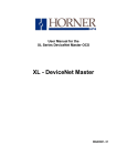
8. Finally, go to the Data Watch Window and display %AI2 as an integer. You will see the free-running
counter clocked by the 10MHz oscillator.
To show some control over the counter, turn on %Q23 (%Q15 + (9-1) = %Q23), which is the mask bit,
and then turn on %Q21 (%Q13 + (9-1) = %Q21), which is the Aux1 bit. The counter stops counting (as a
direct result of turning Q21 on) and is cleared to 0.
Turn off %Q21 and the counter resumes counting.
Figure 7 - Example 1 - Data Watch Window
Information subject to change without notice.
Cscape and SmartStack are trademarks of Horner APG, LLC.
SUP0776-02
26 JAN 2005
PAGE 15
IMPORTANT INFORMATION: PLEASE READ BEFORE USING HSC600 / HSC601.
Example 2: Using an Event Counter
When configuring an Event Counter, use Option 1 or 2 or 7 depending on your application. In Example
2, Option 1 is used.
Note: The HSC has a detailed supplement (SUP0265). See Technical Support at the end of this
document to locate and download the supplement from the web.
Selecting Option 1
1. Install the HSC SmartStack module and start the initial configuration (page 11) and perform steps 1-3.
In this Example 2, it is assumed that the first slot contains a mixed digital module and the HSC
is placed in the second I/O slot.
Figure 1 – Example 2 - Option 1 Selected
2. Select Option 1. Then, click the Configure button.
Information subject to change without notice.
Cscape and SmartStack are trademarks of Horner APG, LLC.
PAGE 16
26 JAN 2005
SUP0776-02
IMPORTANT INFORMATION: PLEASE READ BEFORE USING HSC600 / HSC601.
Configuring HSC Using Option 1
3. The HSC Configuration screen for Option 1 appears. Click the check boxes for:
1. Enable Counter 1
2. Under Mode, select 10 MHz Osc
3. Latch, Load, Clear and Enable from Ladder
Figure 2 – Example 2 - Option 1 Configuration
You are now looking at your configuration choices on the screen as shown in Figure 2. To complete the
configuration, press OK. You are now looking at the screen in Figure 1. Press the I/O Map tab at the
top of the screen.
Information subject to change without notice.
Cscape and SmartStack are trademarks of Horner APG, LLC.
SUP0776-02
26 JAN 2005
PAGE 17
IMPORTANT INFORMATION: PLEASE READ BEFORE USING HSC600 / HSC601.
Viewing the I/O Map
4. The following screen appears.
Figure 3 – Example 2 - High Speed Counter I/O Map with Option 1 Selected
Look at the I/O Map as shown in Figure 3. In this example, the High Speed Counter is the second module
on the stack and there is a mixed digital I/O module in the first position. Therefore the HSC digital I/O
starts at register address 9 and the analog I/O starts at 1. Any reference to the digital I/O on the HSC
needs to be offset by the starting register address minus one. (e.g. %I1 on the HSC is located at %I9 in
the Cscape register map [%I1 + {9-1} = %I9]).
Click OK and then download the configuration to the OCS/RCS. No ladder program is needed for this
example.
Information subject to change without notice.
Cscape and SmartStack are trademarks of Horner APG, LLC.
PAGE 18
26 JAN 2005
SUP0776-02
IMPORTANT INFORMATION: PLEASE READ BEFORE USING HSC600 / HSC601.
Viewing Data Watch Window (HSC, Option 1)
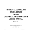
5. Now go to the Data Watch Window. Select the Controller pull-down menu in Cscape and click Data
Watch. Display %AI2 as a DINT (Double Integer). You will see 0 in the counter.
To allow the counter to count, turn on the enable bit located at %Q34, this is the 26th bit in the HSC
register map. With the HSC starting at 9 as shown in the I/O Map of Figure 3, turn on %Q34 (%Q26 + (91) = %Q34). You will see the free-running counter clocked by the 10MHz oscillator.
Now, turn off %Q34 (%Q26 + (9-1) = %Q34) the Enable bit. The counter stops counting, and you can see
the count value in %AI2/3.
Note: If Option 7 had been selected, the counter continues to count with the Enable bit turned off,
because enable is latched. Turning on the Clear bit, the 27th bit in the HSC register map, turns off the
Enable and clears the counter to 0.)
To clear the counter to 0, turn on the Clear bit at %Q35 (%Q27 + (9-1) = %Q35).
Figure 4 – Example 2 – Data Watch Window
Information subject to change without notice.
Cscape and SmartStack are trademarks of Horner APG, LLC.
SUP0776-02
26 JAN 2005
PAGE 19
IMPORTANT INFORMATION: PLEASE READ BEFORE USING HSC600 / HSC601.
What Additional Information Is Important To Know?
Data Consistency Issue During Counter Accumulator Register Access (Accumulator Register is
not Latched)
Applications required to read the counter accumulator registers during counter operation need to
employ the latched values. Latched values are not required for display purposes. (Types of Control
Signals are discussed later in this section.)
Issue: The accumulator registers of option 1, 2, 3, and 7 counters contain Double Integer values. (That is,
they are 24 or 32 bit registers.) If a count occurs coincident with the controller’s access to the accumulator
register, erroneous data can result. This is not an issue for the option 4 accumulator registers, because
they are Integer values. (They are 16 bit registers.) The registers in question are as follows (assuming
that the module’s AI registers begin at AI1):
See %AI Register Table for more details on page 6 in this guide.
Option 1:
AI2/3 (Counter 1 count or frequency, use Latch and AI6/7)
AI4/5 (Counter 2 count or frequency, use Latch and AI8/9)
Option 2:
AI2/3 (Counter 1 count, use Latch and AI6/7)
AI4/5 (Counter 2 count, use Latch and AI8/9)
Option 3:
AI2/3 (Count value, no latch available, use CAM Image)
Option 4:
AI2 (Counter 1 count, no latch available, read accumulator directly)
AI3 (Counter 2 count, no latch available, read accumulator directly)
Option 7:
AI2/3 (Counter 1 count, use Latch and AI6/7)
AI4/5 (Counter 2 count, use Latch and AI8/9)
Types of Control Signals (Options 1, 2, and 7 only)
Note: The following definitions are taken from the HSC Supplement (SUP0265). See Technical
Support at the end of this document to locate and download the supplement from the web.
Each counter (if enabled) is controlled by the following control signals.
LOAD: Setting the Load signal to Logic 1 forces the count to the Load Value. The Count remains at the
Load value until the Load signal is reset to Logic 0. The count then starts from that value and increments
or decrements depending on the direction of the count.
ENABLE: Setting the Enable signal to Logic 1 allows the Counter to count. When the Enable signal of
an option 1 or 2 counter is set to Logic 0, counting is inhibited. When the Enable signal of an option 7
counter is set to Logic 0, counting continues. Use the Clear signal to stop counting.
CLEAR: Setting the Clear signal to Logic 1 clears the counter to zero, and the count remains at zero
until the Clear signal is reset to Logic 0
LATCH: The current counter value is latched into the counter's Latch register on the rising edge of the
Latch signal. The counting function is not disturbed by the latch. The register data is not reloaded until the
following Latch signal's rising edge appears.
Information subject to change without notice.
Cscape and SmartStack are trademarks of Horner APG, LLC.
PAGE 20
26 JAN 2005
SUP0776-02
IMPORTANT INFORMATION: PLEASE READ BEFORE USING HSC600 / HSC601.
NOTES
Information subject to change without notice.
Cscape and SmartStack are trademarks of Horner APG, LLC.
SUP0776-02
26 JAN 2005
PAGE 21
IMPORTANT INFORMATION: PLEASE READ BEFORE USING HSC600 / HSC601.
Technical Support
For assistance and manual updates, contact Technical Support at the following locations:
North America:
(317) 916-4274
www.heapg.com
email: [email protected]
Europe:
(+) 353-21-4321-266
www.horner-apg.com
Information subject to change without notice.
Cscape and SmartStack are trademarks of Horner APG, LLC.
PAGE 22
26 JAN 2005
SUP0776-02
IMPORTANT INFORMATION: PLEASE READ BEFORE USING HSC600 / HSC601.
NOTES
Information subject to change without notice.
Cscape and SmartStack are trademarks of Horner APG, LLC.