1
Maintenance Procedures
®
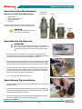
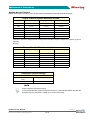
EXTRACTION TOOLS
Part Number
EXTOOL07
(Ø35)
EXTOOL08
(Ø39)
EXTOOL12
(Ø49)
EXTRACTION TOOLS
Where Used
Valve Disk
Nozzle Type
VD0035
Where Used
Part Number
Valve Disk
Nozzle Type
Pico
VD0088B
Femto
VD0033
Pico
VD0094B
Femto
VD0085
Femto
VD0108B
Femto
VD0089
Femto
VD0109B
Femto
VD0102
Femto
VD0074B
Pico
Pico
EXTOOL10P
('V' Guide)
VD0013
Centi
VD0110B
VD0022
Centi
VD0075B
Centi
VD0069
Centi
VD0111B
Centi
VD0034
Pico
VD0106B
Deci
VD0036
Pico
VD0087B
Femto
VD0037
Pico
VD0093B
Femto
VD0038
Pico
VD0065B
Pico
VD0027
Centi
VD0066B
Centi
VD0028
Centi
VD0031
Deci
VD0032
Deci
EXTOOL10P1
('V' Guide)
Terminal End Removal and Installation
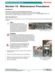
Although this procedure shows a nozzle terminal end, the process is the same for manifold terminal ends.
Terminal End Removal
1. If the terminal end is covered with plastic, warm the terminal end prior to removing the element sleeve.
CAUTION
Care must be taken when removing the
element sleeve as not to damage the ceramic sleeve or terminal nut.
5
4
3
2
1
2. Grip the element sleeve at the threaded area and turn counter clockwise. If the wires rotate with the sleeve, damage
may result.
3. Remove the seal.
4. Remove the set screw from the ceramic sleeve.
5. Remove the power leads.
Figure 12-3 Nozzle Terminal Assembly
1. Nozzle Flange 2. Ceramic Insert
3. Ceramic Sleeve 4. Seal 5. Element Sleeve
Terminal Installation
Although this procedure shows a manifold, the process is the same for nozzle terminal ends.
NOTE
Please contact Mold-Masters Spare Parts Department to ensure you have the correct repair kit
and crimping tool.
Hot Runner User Manual
Not under documentation control if printed. May be revised without notice. Electronic version is available at www.moldmasters.com
12-2
Revision 14
©06-2011