1
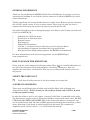
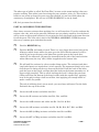
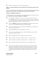
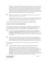
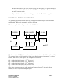
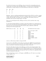
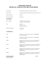
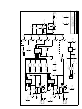
MOTM-120 Sub-Octave Multiplexer
Assembly Instructions
and User’s Guide
Synthesis Technology
6625 Quail Ridge Dr.
Fort Worth, TX 76180
(817) 281-7776
www.synthtech.com
May, 1999
MOTM-120 PARTS LIST
Please carefully check that all parts are in your kit. If you have a suspected shortage,
please call or email. If you get free extra stuff, keep it for next time.
Capacitor bag, containing the following 18 parts:
3ea 10mfd, 50V Electrolytic
C3, C4, C6
3ea 220pf ceramic axial
C12, C15, C18
1ea 0.47mfd (470N) yellow box polycarbonate
C7
11ea 0.1mfd (104) ceramic axial
C1, 2, 5, C8-11, C13, 14, 16, C17
Resistor bag, containing the following 23 parts:
8ea 100K 5% (brown, black, yellow)
7ea 10K 5% (brown, black, orange)
3ea 1K 5% (brown, black, red)
2ea 2M2 5% (red, red, green)
2ea 4M7 5% (yellow, violet, green)
1ea 33K 5% (orange, orange, orange)
R4 - R9, R11, R12
R1, R2, R3, R16, R17, R21, R22
R13, R14, R19
R18, R23
R15, R20
R10
IC bag, containing the following 8 parts:
2ea 74HC161 counter
1ea 74HC08 quad AND gate
1ea 74HC157 quad 2:1 mux
2ea LM311 comparator
1ea TL072 dual op amp
1ea LM78L05 5V voltage regulator
U1, U2
U3
U5
U7, U8
U6
U4
Misc #1 bag, containing the following 6 parts:
2ea Axial ferrite beads (plain, gray things)L1, L2
3ea SPDT toggle switch
SW1, SW2, SW3
1ea MTA-156 power connector
JP1
Knobs, 6ea, ALCO PKES90B1/4
Jacks, 3ea Switchcraft 112A
SYNTHESIS TECHNOLOGY
MOTM-120 ASSEMBLY
WWW.SYNTHTECH.COM
PAGE 2
PAGE 2 MOTM-120 PARTS LIST
Pots, containing the following:
4ea 100K linear, Spectrol 149
2ea 100K linear, Bourns 91 (panel mount)
VR1-4
VR5 & VR6
Front panel
Mounting bracket
Wire bag, containing the following 10 wires:
2ea RG-174 coax, 4 1/2 inches
1ea RG-174 coax 7 inches
4ea red/black twisted pair
1ea orange/white twisted pair
1ea yellow 3 ½ inches
1ea blue wire 2 inches
Hardware bag, containing:
4ea #8-32 x 3/8 black screws (for mounting module to rack)
4ea #6-32 x 1/2 zinc screws (for attaching pc board to bracket)
4ea ¼ inch aluminum spacers
6ea #6 KEPS nuts (2 for attaching bracket to front panel, 4 for pc board)
6ea small heatshrink tubing
5ea small tie-wraps
Organic Solder
No-clean Solder
PC Board, MOTM-120 REV A
Power cable
SYNTHESIS TECHNOLOGY
MOTM-120 ASSEMBLY
WWW.SYNTHTECH.COM
PAGE 3
GENERAL INFORMATION
Thank you for purchasing the MOTM-120 Sub-Octave Multiplexer. If you have any issues
concerning the building or use of the kit, please contact us at (888)818-MOTM or by email:
[email protected]
This kit should take the average builder between 2 and 3 hours. However, please remember
this is NOT a speed contest, it is an accuracy contest. There is no rule that you have to
complete the entire kit in one session (as long as you wash the flux off!).
Successful kit-building relies on having the proper tools. Here is a list of what you will need
to build your MOTM-120.
*
*
*
*
*
*
*
*
Soldering iron, 50W max power
Needle-nose or chain-nose pliers
Diagonal cutters
Wire strippers
Philips-head screwdriver
5/16 and ½” nut drivers and an Allen key set for securing the knobs
Lead bending tool (optional, but makes the job go much faster)
Heat gun for heat-shrink tubing (optional, but HIGHLY recommended)
For more information of tools used and suggestions, see the MOTM FAQ at
www.synthtech.com
HOW TO FOLLOW THE DIRECTIONS
Please read the entire instruction before proceeding. There may be valuable information at
next to it. After you
the end of the instruction. Each instruction has a check box
complete the instruction, check the box. This way you can keep track of where you are in
the process.
VERIFY THE PARTS LIST
Verify that all of the parts are in the kit as shown on the parts list.
A WORD ON SOLDERING
There are 2 very different types of solder used in the kit. Most of the soldering uses
‘Organic Flux’ solder. This is strictly for use on the pc board, and is NOT to be used
on the front panel wiring!
In order for solder to ‘stick’ to the copper, a chemical called ‘flux’ is embedded in the solder.
The flux leaves a residue on the pc board that should be cleaned with warm water. DO NOT
USE SOAP OR OTHER CLEANSERS. Most of the parts in the kits are ‘waterproof’, and
can be washed in the sink. The flux is OSHA approved for flushing down the drain, so don’t
worry about that! A soft brush is used to gently scrub the board. We recommend a
‘fingernail brush’, which is about 1” x 2” and be found for about $1.
SYNTHESIS TECHNOLOGY
MOTM-120 ASSEMBLY
WWW.SYNTHTECH.COM
PAGE 4
The other type of solder is called ‘No Clean Flux’, because as the name implies it does not
require washing. This solder is used on wiring the pots, switches, jacks, etc. This solder is
harder to use on the pc board, because even when melted it is not very fluid (about the
consistency of toothpaste). We will use it VERY SPARINGLY on the pc board.
OK, let’s get started on the board!
PART #1: SOLDERING THE RESISTORS
Since there are more resistors than anything else, we will start here. If you do not know the
resistor color code, refer to the parts list. Resistors are not polarity sensitive, but the board
will be easier to debug (and look nicer) if you point the first color band in the same direction
for all the parts. The color code is also in the GENERAL ASSEMBLY GUIDE document
that every customer gets with their first order.
Find the RESISTOR bag.
Find the MOTM-120 blank pc board. There is a copy (larger than actual size) of the
silkscreen which shows where the parts go at the end of this document. It will be
useful if you locate the part on the print first, put the part in the board, then
‘check off’’ the silkscreen. All parts are inserted from the side of the board with the
white silkscreen (the “top” side). Solder is applied on the ‘bottom’ side.
We will stuff the resistors by value to make things easier. The resistors (and other
long-leaded parts) are inserted on 0.4 inch spacing. The important thing is to be sure
that the part is sitting all the way down on the board. Push the leads in the holes,
push the part on the board, and then bend the leads on the bottom outwards to a 45
degree angle (roughly!). This is called ‘cinching the leads’: it keeps the part from
falling out! From the bottom of the board, solder (with the organic flux), applying
heat to the pad for about a half second first, then applying just enough solder to
make a small, flat puddle.
The rule of soldering: don’t use too much, you can always add more! Cut the leads
flush with the top of the solder.
Locate the 33K resistor and solder into R10.
Locate the 1K resistors and solder into R13, R14, and R19.
Locate the 100K resistors and solder into R4 - R9, R11 & R12.
Locate the 10K resistors and solder into R1, R2, R3, R16, R17, R21, and R22.
Locate the 2M2 (2.2Meg) resistors and solder into R18 and R23.
Locate the 4M7 (4.7Meg) resistors and solder into R15 and R20.
SYNTHESIS TECHNOLOGY
MOTM-120 ASSEMBLY
WWW.SYNTHTECH.COM
PAGE 5
That should be all of the resistors! And guess what: you are about 1/3 of the way done!
PART #2: BOARD WASH #1
Verify all the resistors are in the correct position.
Verify all the resistors are flat on the board. Correct if needed.
Wash the board in warm water only, gently scrubbing both sides.
Shake the board a couple of time, blot dry with an old towel (the leads will frazzle
the good towel). Let dry about 15 minutes.
PART #3: CAPACITORS
Locate the CAPACITOR bag.
Locate the 220pf axial ceramic caps (marked 221). Solder into C12, C15 and C18.
Locate the 0.1mfd axial ceramic caps. These look just like the 220pf caps, but are
marked 104. Solder into C1, C2, C5, and C8-C11, C13, C14, C16 and C17.
Locate the 0.47mfd yellow box cap. It is stamped 474 on the top. Solder into C7.
Locate the 10mfd electrolytics. Note that there is a stripe on the NEGATIVE
terminal. The pc board has a + on the POSITIVE terminal. Carefully stick the
capacitors into C3, C4 and C6 with the stripe away from the + pad on the board.
SYNTHESIS TECHNOLOGY
MOTM-120 ASSEMBLY
WWW.SYNTHTECH.COM
PAGE 6
PART #4: MISC STUFF
Almost done with the parts on the pc board! This will finish up the soldering with the
organic flux.
Locate the MISC #1 bag and the IC bag.
Locate the ferrite beads. They are axial parts, gray colored with no markings. These
are non-polar, and are soldered into L1 and L2.
Locate the MTA-156 power connector. Solder into JP1. Note that the connector has
a ‘locking tab’ on one side. This side is the “inside”, towards the middle of the pc
board. The tab is next to the 2 ferrite beads.
Note the silkscreen symbol for JP1 has a line on one side, indicating this is the side
where the locking tab goes.
Locate the IC bag. IMPORTANT: all of the ICs (except U4) point the same way
when soldered in the pc board. Each IC has a small notch in the end of the plastic
body, on the top of the part. These notches face towards the bottom edge of the
pc board.
Locate the LM311N comparators. Solder into U7 and U8. Note that Pin #1 is the
square pad. Pin #1 is the pin near the very small ‘dot’ in the top of the part.
Locate the TL072 op amp. Solder into U6.
Locate the 2 74HC161 counters. Solder into U1 and U2.
Locate the 74HC157 quad 2:1 mux. Solder into U5.
Locate the 78L05 voltage regulator. It has a flat side that has the lettering. The
flat side faces the white “U4” on the pc board. The center pin is slightly bent
forward. Press the part in until about 1/8” of lead is still exposed. DO NOT try to
stuff it all the way down flush with the pc board. Solder into U4.
Locate the 74HC08 quad AND gate. Solder into U3.
PART #5: WASH THE BOARD AGAIN
Verify all the parts are in the correct locations. Check C3, C4 & C6
orientation (all of the stripes are pointing the same way, up).
Inspect the solder joints. Any solder shorts? Too much solder? Missing joints?
SYNTHESIS TECHNOLOGY
MOTM-120 ASSEMBLY
WWW.SYNTHTECH.COM
PAGE 7
Wash the board under warm water. Scrub gently. Dry.
THIS IS A GOOD STOPPING PLACE TO REST OR PUT THE KIT AWAY UNTIL
LATER.
You are now finished with the Organic flux solder. All soldering past this point is
using the No-Clean solder. You do not have to wash the board anymore.
PART #6: FINISHING THE PCB
You will now solder in the remains parts on the pcb in preparation for wiring to the front
panel. USE THE NO-CLEAN SOLDER. BE CAREFUL!
Locate the Spectrol #149 pots. 4 go on the pc board, and 2 mount on the front
panel. NOTE: in order for the pc board to properly align into the front panel, each
pot must be absolutely flat on the pc board, with the shafts pointing away from the
pc board. Solder the pots into VR1 - 4. Clip the leads off.
Locate the WIRE bag. Note that the pre-stripped wires all have a short end and
a longer end. THE SHORT END GOES IN THE PC BOARD.
Locate the white/orange twisted pair. Solder the ORANGE wire into SW2, in the
hole marked 1 (square pad).
Solder the WHITE wire short end into SW2, in the 2 hole.
Locate one of the red/black twisted pairs. Solder the RED short end into VR6,
into the hole marked 1 (round).
Solder the BLACK short end into VR6, hole marked 2 (square).
Solder a red/black twisted pair into VR5: red wire in 1 and black wire in 2.
Solder a red/black twisted pair into SW3: red wire in 1 and black wire in 2.
Solder a red/black twisted pair into SW1: red wire in 1 and black wire in 2.
Locate the 3 pieces of RG-174 black coax cable. Again, note that one end has
longer wires stripped than the other. The short ends will go in the pc board in
positions J1 to J3. Look at the pc board. Notice that in positions J1 - J3, there
is a large hole pad (lower pad) and a smaller pad (top hole). The braided wire
is soldered into the larger hole. The smaller, inner conductor goes in the top
hole.
SYNTHESIS TECHNOLOGY
MOTM-120 ASSEMBLY
WWW.SYNTHTECH.COM
PAGE 8
Note there is a row of ‘plain’ holes along the bottom, under J1 - 3. These holes are for
threading the small white tie-wraps for holding the coax against the pc board. The
holes are designed so that the coax lies in between the 2 holes. The tie wrap enters
the left hole from the top, comes out the right hole from the bottom, and is then
secured so that the coax is tightly held against the top of the pc board. Note that the
tie wraps must thread from the top, or there may not be sufficient room between the
pc board and the mounting bracket. The excess tie wrap is cut off.
Solder, then tie-wrap the 2 short coax cables J2 & J3. Trim the excess tie-wrap.
Solder and tie-wrap the longer coax into J1.
NOTE: because of the way the coax is made, chances are more of the braid will go in
the bottom hole than the inner conductor. This is normal, unlike all the other parts
and wires. The secret is to get the coax firmly soldered and tied down.
YOU ARE NOW FINISHED WITH THE PC BOARD WORK! BREAK TIME.
PART #7: FRONT PANEL PREPERATION
You will now attach components to the front panel. It is HIGHLY recommended that you
use a set of hollow shaft nut drivers, NOT PLIERS, to tighten the nuts. This prevents
scratching. NOTE: all references to part orientation is from the REAR of the panel.
Locate the 3 Switchcraft jacks. Notice that from the rear, there is a beveled corner.
This corner is ALWAYS CONNECTED TO GROUND, USUALLY WITH THE
BRAIDED CONDUCTOR. Each jack has a flat washer, a lockwasher, and a ½” hex
nut. Remove the nuts and washers from each jack. Place aside. Keep the lockwasher
on the jacks.
Insert the 3 jacks/lockwashers, with the beveled corner in the upper right corner,
into the 3 holes. Place the flat washer on the jack, then the hex nut. Hold the jack
with one hand on the backside, keeping it ‘square’. Tighten the hex nut with a nut
driver. NOTE: when tight, not much of the exposed threads of the jack are exposed.
Check to see that each jack has the bevel in the upper right corner, and all jacks are
neatly lined up.
Locate the 3 SPDT toggle switches. Note that on one side of the metal plate,
are the numbers 1, 2, 3 or ON and ON (this will depend on the switch
manufacturer). We will refer to the switch lugs as ‘top’, ‘middle’, and ‘bottom’.
Remove the hex nut (keep the lockwasher on), stick the switches in the holes with
the #1/ON terminal at the top. Place the hex nut on the switch and tighten. Be sure
the switch is straight up and down: it is easy to get it slightly off-center. The
numbers/letters are on the right side of the switch. Place into MIX A, MIX B, and
MODE holes. If your switch says ON and ON, place the switch in the hole so the ON
& ON side is to the right (not that it matters, but let’s be consistent!)
SYNTHESIS TECHNOLOGY
MOTM-120 ASSEMBLY
WWW.SYNTHTECH.COM
PAGE 9
Locate the 2 remaining 100K Bourns pots. Remove the first hex nut, keeping the
lockwasher and 2nd nut on. Insert the pots (one at a time) into the A IN and B IN
holes, with the 3 leads pointing down towards the jacks.
CAREFULLY, tighten the hex nut, holding the pot with one hand to keep the 3
leads pointing downwards. DO NOT OVERTIGHTEN!
You are now ready to attach the pc board to the bracket, and then wire up to the panel.
See the illustration at the end of the document.
PART #8: ATTACH PC BOARD TO BRACKET & PANEL
In the HARDWARE bag, locate 4 #6-32 x ½ screws, 6 #6 KEPS nut, and 4 spacers.
Locate the mounting bracket. The pc board attaches to the bracket, with the 4
screws threading from the top of the board, through the spacers, through the
bracket, and then out the bottom of the bracket. The #6 KEPS nut attaches on the
bottom of the bracket. Note the bracket has 2 long mounting flanges with a hole
in each. These attach to the 2 threaded studs sticking out of the rear of the panel.
The 4 pots each stick in it’s panel hole when the bracket is screwed down on the 2
threaded posts.
Attach the pc board to the bracket. The 2 mounting flanges are located in between
VR1 & 2, and in between VR3 & 4. Note that the bracket holes for the pc board are
actually oblong. Tighten then 4 KEPS nuts on the bottom.
THIS IS A VERY IMPORTANT STEP, SO PAY ATTENTION AND READ ALL OF
IT BEFORE PROCEEDING!
Note that each of the 4 pots on the pc board have 2 hex nuts and a flat washer.
Remove the first hex nut and the washer. Set aside.
Make sure the remaining hex nuts on each pot on the pc board is screwed on all the
way. Tighten by hand each hex nut.
Now you will see if the pc board needs to be adjusted on the bracket. Carefully
insert the 4 pot shafts through the front panel, sliding the bracket flanges over
the 2 threaded studs. Slide the bracket all the way forward until the hex screws
on the pots are touching the front panel. Look at the bracket flanges: they should be
flush on the panel as well. If either the bracket hits first OR the bracket flanges are
not yet flush, the pc board needs to slide in the bracket (either forwards or
backwards). Loosen the 4 KEPS nuts slightly to adjust the pc board.
It is VERY important that all 4 hex nuts on the pots AND the 2 bracket flanges are
all flush to the front panel (NO air gaps!).
SYNTHESIS TECHNOLOGY
MOTM-120 ASSEMBLY
WWW.SYNTHTECH.COM
PAGE 10
Now use 2 of the #6 KEPS nuts to tighten the bracket to the panel.
For each pot, place the flat washer on the threads, then the hex nut. Tighten.
PART #9: FINISH WIRING TO THE PANEL
Attach and solder the RED wire on SW1 to the bottom terminal of the ‘MODE’
switch.
Attach and solder the BLACK wire on SW1 to the middle terminal of the
‘MODE” switch. There is NO wire connected to the top terminal.
Attach and solder the RED wire on SW3 to the bottom terminal of the
MIX B switch.
Attach and solder the BLACK wire on SW3 to the top terminal of the
MIX B switch.
Attach and solder the ORANGE wire on SW2 to the bottom terminal of the
MIX A switch.
Attach and solder the WHITE wire on SW2 to the top terminal of the
MIX A switch.
In the WIRE bag, find the single piece of yellow wire.
Solder carefully to the middle terminal of MIX A switch.
The other end will go to the IN A pot, on the LEFT terminal. Find a piece
of small heat-shrink tubing. Place the tubing over the wire, sliding it towards
the switch. Then, make a little bend in the yellow wire. Insert the wire through
the hole in the pot lead and solder. Leave the heat shrink tubing where it is for now!
Locate the red/black twisted wires in VR6. They also solder to the IN A pot leads.
The RED wire goes on the middle lead, and the BLACK wire goes on the right lead.
Before soldering, place a small piece of heatshrink on each wire (you may have to
un-twist the wire once or twice!) As before, make a SMALL ‘J’ shaped bend in the
wire, attach the two together, and solder.
Now that all 3 leads are on the IN A pot (yellow on the left, red in the middle, black
on the right) slide each heatshrink tube over the pot leads, covering the solder joint.
Using a heat gun (low setting!!) shrink the tubing over the leads. You can also place
your soldering iron CLOSE BUT NOT TOUCHING the tubing and the radiant heat
will shrink it.
SYNTHESIS TECHNOLOGY
MOTM-120 ASSEMBLY
WWW.SYNTHTECH.COM
PAGE 11
Find the BLUE wire. Solder one end to the MIX B switch, terminal #2 (middle).
The other end goes to the LEFT terminal of the IN B pot. Solder as before: slide
on the heatshrink, attach the wire to the lead.
Untwist some of the red/black VR5 wire. Slide on the heatshrink, and as before
solder the RED wire to the MIDDLE terminal of the IN B pot, Solder the BLACK
wire to the RIGHT terminal. Slide the tubing over the pot leads and shrink.
The last thing to do is to solder the coax cables to the jacks. You will start with J3,
and work backwards to J1. In this manner you will solder left to right on the jacks.
Solder the coax on J3: this is the OUT. Solder the braid to the ground lug (beveled
edge), and the conductor to the left lug. The top lug is NOT connected.
Solder the coax on J2: this is IN B (middle jack). First, solder a wire scrap from a cut
resistor lead from the TOP to the BEVELED lug. Then, solder the center conductor
on the left lug and the braid on the beveled lug. Trim the wire scrap so it doesn’t get
in the way. You may want to solder the TOP lug first, then insert the coax braid on
the beveled lug before soldering. This shorts out the IN B when no signal is applied
(prevents erratic sub-octaves from being triggered by the IN A signal).
Solder the coax on J1: this is IN A . Braid to beveled and center to left lug.
Rotate all of the front panel pots fully counter-clockwise. Locate the KNOBS.
Notice each knob has a thin white line on it. Place the knob on the pot shaft,
align the white line to the ‘0’ tick mark and tighten the hex screw. The silver part of
the knob has a protective clear plastic overlay that can be removed if desired. Gently
rub with your fingernail and it will peel off.
************************************************************************************
CONGRATULATIONS! YOU HAVE FINISHED BUILDING THE MOTM-120!
************************************************************************************
SYNTHESIS TECHNOLOGY
MOTM-120 ASSEMBLY
WWW.SYNTHTECH.COM
PAGE 12
VERIFYING THE UNIT IS FUNCTIONAL
You will now verify the MOTM-120 in both SUB and CROSS modes.
Apply +-15VDC to the unit. Power is applies through JP1. -15V is on the
left, the 2 center pins are ground, and the right pin is +15V. A MOTM-900 supply is
highly recommended.
Set the MIX switches to NORM (normal). Set all pots to 0.
Set the MODE switch to SUB (sub-octaves).
Apply an audio frequency, of at least 1V pk-pk to the A IN jack. IMPORTANT
NOTE! The input circuitry (see Theory of Operation) requires that the input signal
be greater than 100mv pk-pk or the circuitry will not operate! This prevents false
and erratic triggering with low-level, noisy signals. Therefore, use the output of a
VCO or other high-level source. If you synth has HI and LOW outputs, use HI.
Use a non-pulse/square wave (a sine or triangle wave is good, or a string patch).
Connect an amplifier or oscilloscope to the OUTPUT jack. WARNING! The
MOTM-120 is designed for use within a modular synthesizer, Therefore, the
output level (with all pots at 10) is 10V pk-pk. Most audio amplifiers are designed
to operate with 1 or 2 volts pk-pk maximum. Be careful when using such an
amplifier with full level output signals.
Slowly turn up the A IN pot. You should hear the input signal. Now, switch the
MIX A switch to SQUARE. You should hear the different tonal quality. The volume
may be louder or softer than the input.
Turn down the A IN pot. One at a time, turn up the SUB pots. You should hear
(or see on a scope) the 4 different sub-octaves. Each one is 1 octave below the next
one. If you input signal is too low a frequency, the 4th sub-octave may be only a
clicking sound! Increase the pitch of the input.
If you do not hear the 4 distinct sub-octaves, proceed to the Troubleshooting Guide.
Flip the MODE switch to CROSS.
Apply a second input signal to the B IN. If you have a LFO or low frequency (<10Hz)
signal, this will make testing much easier! If not, apply any high-level signal.
Set each SUB pot, and A IN (not B IN) to ~4. Set B IN to 0.
Let’s assume that you have an audio signal into IN A, and a LFO to IN B. What you
should hear is a 16 “note” pattern, that repeats. What you are hearing is a binary
count of each sub-octave generated by A IN being gated to the output by B IN. If
you increase the frequency of B IN, the pattern speeds up.
SYNTHESIS TECHNOLOGY
MOTM-120 ASSEMBLY
WWW.SYNTHTECH.COM
PAGE 13
If both A IN and B IN are audio signals, what you should hear is a giant, constantlymoving tone (this is REAL hard to describe! There are .WAV files of these sounds
at www.synthtech.com).
If you feel that this mode is not working, proceed to the Troubleshooting Guide.
ELECTRICAL THEORY OF OPERATION
The following discussion explains how the circuit operates, and suggests area of possible
modification. Refer to the schematic and block diagram.
This is a simplified block diagram of how the MOTM-120 operates.
CLIPPER
4-BIT COUNTER
2:1 MUX
DIGITAL R.M.
MIXER
IN A
IN B
OUT
CLIPPER
4-BIT COUNTER
The “heart” of the MOTM-120 are the two 4-bit counters, which are 74HC161s (U1 and U2).
The counters have a clock input (pin 2) that causes the 4 outputs to increment, in a binary
fashion, from 0 to 15, then repeat. The 4 outputs are as follows:
QA - divides the clock input by 2 (1st sub-octave)
QB - divides the clock input by 4 (2nd sub-octave)
QC - divides the clock input by 8 (3rd sub-octave)
QD - divides the clock input by 16 (4th sub-octave)
Since these counters want the clock signal to go between 0 and +5V, in a nice sharp
manner, we have to process our input signal.
SYNTHESIS TECHNOLOGY
MOTM-120 ASSEMBLY
WWW.SYNTHTECH.COM
PAGE 14
The inputs are shaped into square/pulses of 0 to +5V by a special circuit called a
comparator. Since the 2 inputs use identical circuits, we will discuss IN A.
The LM311 comparator (U7 & U8) is used, since we use it with a “trick”: the LM311 has an
open-collector output with the emitter of the output transistor brought out to a separate pin
(pin 1). Since we want a 0-5V swing to make the counters happy, the emitter is tied to
ground, and the collector is ties to +5V through a pull-up resistor (R14 and R19).
Why is this such a big deal? Because our audio inputs swing + and -, we need to power the
LM311 from bipolar supplies, and other types of comparators (like the LM339) internally
tie the emitter of the output transistor to the - supply!
Now we need to use the comparator to “square up” our inputs. The comparator has 2 inputs,
+ and -. Look at U7. On pin 3 (- input), we tie the input signal, through a noise filter
compromised of R17 and C12. On the + input, there is a reference voltage derived from R18
and R16. The voltage on this pin is about :
Vref = (R16)*(+5V)/(R16 + R18) = 23mv
However, notice feedback resistor R15 is tied in as well. This causes hysteresis: the
reference voltage move up and down as the output swings from 0V to +5V. Hysteresis
prevents false switching of the output of the comparator when the input signal is slowly
changing (like from a LFO).
The effect of R15 causes the trip level of the comparator to be roughly 80mv pk-pk. If you
try to apply a signal lower than 80mv pk-pk, the comparator ignores it, and the counter will
not count. No output!!
A fair question is: why isn’t the comparator input tied to ground? The answer is: because
many older synth have tiny levels of noise on the outputs, even if no notes are being played!
This is a noise gate, to eliminate the output noisy from triggering the counters.
Assume we have a strong input, and the counters are operational. Now what??
The output of the counter associated with A IN is fed to 2 places: the quad AND gate (U3)
and to the 2:1 multiplexer, U5. The 74HC157 mux is a simple switch: if the input on pin 1 is
LOW (<.5V) the signals tied to the ‘A’ inputs are connected to the ‘Y’ outputs. If the signal
on pin 1 is HIGH (>+3V) then the ‘B’ inputs are connected to ‘Y’ outputs.
Look on pin 1, and you will see that is where the MODE switch on the front panel is
connected. Pull-up resistor R3 keeps the pin tied to HIGH unless it is in SUB position.
Then, the pin is shorted to ground, or LOW. In this manner, U5 selects whether the mixer
is controlling the sub-octaves from the A IN counter (they are tied to the ‘A’ inputs) or the
outputs from the AND gates.
What’s special about those 4 AND gates? Why, that’s our secret digital ring modulator!
SYNTHESIS TECHNOLOGY
MOTM-120 ASSEMBLY
WWW.SYNTHTECH.COM
PAGE 15
If you look at the inputs to each AND gate, they are tied to the corresponding sub-octave
outputs from each counter (QA to QA, QB to QB, etc). To show how the lowly AND gate is
transformed to a digital ring mod, let’s first examine the truth table of an AND gate:
In1
0
0
1
1
In2
0
1
0
1
Out
0
0
0
1
Hmmmm....don’t see anything immediately that sheds the light. Well, let’s call In1 a control
voltage, and In2 our input signal. If our CV is 0, nothing comes out. If our CV is a 1 (HIGH
voltage), then the input = the output. If you consider how a VCA works, if the CV is
maximum, then in fact the output signal = the input!
Since we are in the digital world, a AND gate is in fact a VCA, and that’s what a ring
modulator is!
So, the innocent-looking AND gate is acting as a ring mod. Another way to think about the
circuit is this: the sub-octaves generated by IN B gate to the mixer, in a binary pattern, the
IN A sub-octaves. You will hear this effect if A IN is audio, and B IN is a LFO. The
following chart will help explain this:
B IN Counter >>>> Qd
0
0
0
0
0
0
0
0
1
Qc
Qb
Qa
A IN Suboctaves Out to mixer
0
0
0
0
1
1
1
1
0
0
0
1
1
0
0
1
1
0
0
1
0
1
0
1
0
1
0
none, all you get is A IN
Sub #1
Sub #2
Sub#1 + Sub#2
Sub#3
Sub#3 + Sub#1
Sub#3 + Sub#2
Sub#3 + Sub#2 + Sub#1
Sub#4
and so on. AIN is always added in, along with B IN.
As you can see, if the B IN is a slow signal, you can here the 74HC157 mux switching the
sub-octave as the pattern shown in the table. If both AIN and B IN are audio frequencies,
what you will hear is a distinctive beating pattern, based on this table.
The mixer (U6) adds the outputs of the AND gates, with the selected input signals. Note
that the outputs of the comparators and the AND gates are all 0 to +5V signals. If you have
the MIX switches set to NORM, and you are using a smaller signal, (say 1V pk-pk) then the
SUB mix will be much louder than the input mix. This can, of course, br compensated for by
carefully adjusting the mixer pots.
Since the digital logic requires a +5V supply, and MOTM uses +15V, there is an on-board
voltage regulator, U4.
SYNTHESIS TECHNOLOGY
MOTM-120 ASSEMBLY
WWW.SYNTHTECH.COM
PAGE 16
USING THE MOTM-120 IN YOUR SETUP
In this section, we will discuss how the MOTM-120 is used in various applications. Of
course, these are only a few things to try. Experiment!
SUB MODE
The SUBoctave mode only requires one input, into the A IN jack. Note that if you are in
SUB mode, the B IN jack is ignored. The B IN pot does nothing.
For the basic use, set the controls as follows:
•
•
MODE switch to SUB
MIX A and MIX B to NORM (normal, the input is mixed “as-is” with the sub-octaves)
Connect an amplifier to OUTPUT, or patch through a mixer (better choice!).
IMPORTANT NOTE!
The MOTM-120 can output voltage levels to 10V pk-pk. Be careful when connecting power
amplifiers directly to the OUTPUT!!
Apply a signal, of at least 1V pk-pk, to the IN A jack. Now, turn up the pots, and you will
hear the lowers octave harmonics being added to your input signal.
Flip the MIX A switch to SQUARE. If your input was not a square/pulse, you should hear
the different harmonics in the output. NOTE: when you are in the SQUARE position, the
full level (+5V) signal is applied to the mixer. This is NOT the case in the NORM position,,
where the input is routed directly to the mixer. Therefore, you will probably need to adjust
the A IN level control.
That’s all there is to it! Any whimpy signal can be “fattened up” by adding suboctaves. You
don’t have to add ALL of them! Sometime a little SUB2 goes a long way.
Don’t think of the MOTM-120 as the last link in your signal-processing chain! Take the
output from a VCO, to the MOTM-120, then into your filters.
SYNTHESIS TECHNOLOGY
MOTM-120 ASSEMBLY
WWW.SYNTHTECH.COM
PAGE 17
CROSS MODE
This mode requires two input signals to function.
This is the most useful and bizarre mode of the MOTM-120. The following are just 3 ways
to use the module, but there are 100s of others as well.
#1 - both inputs are audio signals
If you mix 2 VCOs, and they are not in tune, you hear a beating effect. The beat frequency
is the difference, in Hz, between the 2 harmonically related tones. This is also called
detuning, and is a popular way to increase the fatness of a sound.
The MOTM-120 takes this concept to the next level. Instead of a 2-tone beat, the CROSS
mode produces a 16-note beat!! Why? Because we are switching in the sub-octaves in a 16
step, binary pattern.
Apply 2 audio signals and hear what we mean! Carefully adjust the relative tuning of the
inputs, and you will hear this effect. NOTE: the tuning can be real touchy!! It will greatly
depend on the nature of the 2 inputs you use. The beauty of the MOTM-120 is that you do
NOT need complex inputs to produce complex outputs!! Simple sine and sawtooth waves
can beat to produce wonderfully complex timbres.
You can get even MORE complex outputs if you:
•
•
•
•
Use white or pink noise (see the MOTM-100) as an input
Use 2 VCOs as inputs, and slowly LFO modulate one of them
Play with synching the two inputs
Use a standard synth patch as one input, and a basic waveshape into the other
Again, use the output of the MOTM-120 and filter, ring mod, compress, and distort!
#2 - one input is audio, one input is a LFO
You can get sequencer effects if one input is audio, and the other is a LFO-type signal
(<10Hz). This causes the generated suboctave to be sequentially added to the mixer in a 16step, repeating pattern (see the table in the Theory section).
The MOTM-120 always does this in CROSS mode, it’s just that with a slow input, you can
hear the pattern!
#3 - one input is noise
If you use noise as an input, the counter will clock very fast!
This can create “gated feedback” types of effects. Watch those tweeter levels!!
As you can see, the MOTM-120 is a truly unique piece of signal processing equipment. Just
remember to keep your input signal levels above 100mv pk-pk.
SYNTHESIS TECHNOLOGY
MOTM-120 ASSEMBLY
WWW.SYNTHTECH.COM
PAGE 18
TROUBLESHOOTING GUIDE
If your MOTM-120 does not work, please verify ALL of the following before contacting us.
The following reference directions assume that you are looking at the pc board with the
panel to the right and the power connector to the left.
All of the IC are pointing the same way: all notches are downwards.
The flat side of U4 faces the front panel.
C3, C4 and C6 stripes are both pointing upwards.
The braided wire on the coax goes to the beveled side of the jacks.
There is nothing on all 3 jacks on the top (switched) lug.
The board has all the right parts in all the right places.
No solder shorts or missing joints.
If you still can not get the module to perform correctly, please contact us by phone/fax at
(888) 818-6686 or by email to [email protected]
Thank you for purchasing the MOTM-120 module.
SYNTHESIS TECHNOLOGY
MOTM-120 ASSEMBLY
WWW.SYNTHTECH.COM
PAGE 19
SPECIFICATIONS
MOTM-120 SUB-OCTAVE MULTIPLEXER
Audio Input
100mv pk-pk minimum, 10V pk-pk maximum
Output level
10V pk-pk with A IN, B IN both 3V pk-pk, All pots at 10
Input Impedance
50K min
Output Impedance
1K typical
GENERAL
Power Supply
-15VDC @ 20 ma maximum
+15VDC @ 20 ma maximum
Size
2U x 5U
3.485” x 8.735”
88.5mm x 221.9mm
Depth behind panel
4.375 inches
111.1mm
CONTROLS
A IN
Attenuates either the input signal or the SQUARE
version of the input
B IN
Attenuates either the input signal or the SQUARE
version of the input
SUB 1
Attenuates the first sub-octave into the output mixer
(SUB mode) or the first cross product in the mixer
(CROSS mode).
SUB 2
Attenuates the second sub-octave into the output mixer
(SUB mode) or the second cross product in the mixer
(CROSS mode).
SUB 3
Attenuates the third sub-octave into the output mixer
(SUB mode) or the third cross product in the mixer
(CROSS mode).
SUB 4
Attenuates the fourth sub-octave into the output mixer
(SUB mode) or the fourth cross product in the mixer
(CROSS mode).
SYNTHESIS TECHNOLOGY
MOTM-120 ASSEMBLY
WWW.SYNTHTECH.COM
PAGE 20
112A
J2
-15V
112A
J1
ORA
VCC
C11
0.1M
ORB
VCC
C14
0.1M
VCC
C12
220P
R22
10K
C16
R21
10K
-15V
220P
C15
-15V
3
2
0.1M
R20
4M7
10K
R1
3
2
-15V
2M2
R23
VCC
R17
10K
C13
R16
10K
0.1M
R15
4M7
10K
R2
2M2
R18
VCC
C17
0.1M
41
8
VCC
41
8
VCC
VCC
R19
1K
QA2
QB2
QC2
QD2
R14
1K
QA1
QB1
QC1
QD1
VCC
JP1
1
2
3
4
14
13
12
11
15
14
13
12
11
15
MTA-156
QA
QB
QC
QD
RCO
ENP
ENT
CLK
LOAD
CLR
74HC161
U2
A
B
C
D
U8
LM311
6
5
7
7
10
2
9
1
3
4
5
6
SQA
QA
QB
QC
QD
RCO
ENP
ENT
CLK
LOAD
CLR
74HC161
U7
LM311
6
5
7
7
10
2
9
1
3
4
5
6
U1
A
B
C
D
L2
FERRITE
L1
FERRITE
C9
0.1M
13
VCC
12
QD2
10
QD1
QC2
9
5
QC1
4
QB2
2
1
QB1
QA2
QA1
C3
10M
25V
QA1
CX1
QB1
CX2
QC1
CX3
QD1
CX4
C4
10M
25V
SW3
+15V
2
ORB 1
VCC
11 CX4
8 CX3
6 CX2
3 CX1
C10
0.1M
-15V
VCC
74HC08
U3D
74HC08
U3C
74HC08
U3B
74HC08
U3A
R3
10K
2
SQA
4Y
3Y
2Y
1Y
2
SUB-O
CROSS
3
I
2
G
O
U4
LM78L05
1
OFF-BOARD WIRE
SW1
12
9
7
4
C8
0.1M
A/B
G
74HC157
U5
1A
1B
2A
2B
3A
3B
4A
4B
VCC
SW2
C5
0.1M
1
1
15
2
3
5
6
11
10
14
13
1
ORA
VCC
C6
10M
25V
VR6
100K
VR4
100K
VR3
100K
VR2
100K
VR1
100K
VR5
100K
100K
R9
100K
R8
100K
R7
100K
R6
100K
R5
100K
R4
OFF-BOARD
8
4
7
+15V
U6B
TL072
100K
R11
+15V
U6A
TL072
1
C1
0.1M
1K
R13
C7
0.1M
-15V
6625 QUAIL RIDGE DR.
FORT WORTH, TX
76180
(888)818-MOTM
SYNTHESIS TECHNOLOGY
5
6
8
4
C2
0.1M
112A
J3
MOTM 120 - SUBOCTAVE MULTIPLEXER
Size Document Number
B
M120
Date: September 29, 1998 Sheet
1 of
Title
100K
R12
3
2
-15V
33K
R10
220PF
C18
REV
B
1