1
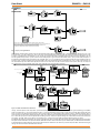
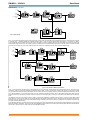
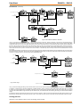
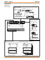
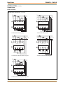
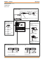
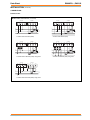
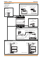
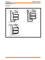
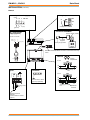
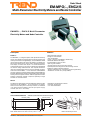
EM-MPO/.., ENC2/S
FUNCTIONALITY
Data Sheet
(continued)
EM-MPO/STAR3
The EM-MPO/STAR3 is a front panel mounted energy analyser
with a multi-segment bright red on black LCD display. It has two
digital outputs for measurement pulses, or alarm indication.
Input Power Supply
The EM-MPO/STAR3 requires 230 Vac or 115 Vac, 35 to 400 Hz,
at 4VA.
Parameters
In addition to the parameters delivered to the ENC2/S, the unit can
display:
Phase to Phase Voltages Vlx-Vly (V)
Neutral Current (A) - Star only
Average Phase Currents (A)
Maximum Demand Phase Currents (A)
Total Maximum Demand Power (kW)
Total Maximum Demand Apparent Power (kVA)
Phase Voltage Total Harmonic Distortions (%)
Total Voltage Total Harmonic Distortion (%)
Phase Current Total Harmonic Distortions (%)
Total Current Total Harmonic distortion (%)
Connection
The unit can be connected in the following configurations:
Single Phase with neutral (1CT)
2 Phase with neutral (2CTs) Diphase
3 Phase (3CTs) Delta
3 Phase with Neutral (3CTs) Star
3 Phase using 2 CTs (2CTs) Delta
CTs must be used. VTs can be used in all configurations., 1 VT
for each phase.
Configuration
The following settings must be configured:
RS485: Default baud rate and parity settings OK, see above.
Protocol must be changed from IEEE to ASCII
RS485 address (modbus): Default setting OK, see above
VTs: If used must be set up. If not used set ratio to 1 (default)
CTs: Must be set up.
Connection: set up to one of the following:
Delta: 3 phase without neutral
Star: 3 phase with neutral
Diphase: 2 phase with neutral
Single-phase: 1 phase with neutral
Pulse Modes
The outputs can be set individually to be sourced from one of the
following parameters:
+ve 3 Phase Active Energy consumed (kWh)
-ve 3 Phase Energy (kWh)
+ve 3 Phase Reactive Energy (kVArh)
-ve 3 Phase Reactive Energy (kVArh)
3 Phase Apparent Energy (kVAh)
Each output also requires the value (‘weight’) of each pulse to
be defined (e.g. 0.01 kWh/pulse)
Relay Mode
Note that it is possible to configure relay 1 to be controlled from the
RS485 bus, but this feature is not available when the ENC2/S is
connected.
The outputs can be set individually to indicate an alarm condition
from one of the following parameters: Total Voltage or Phase
Voltage, VLN, (V)
Total Current or Phase Current, ALN, (A)
Total Power or Phase Power (W)
Total Apparent Power or Phase Apparent Power (VA)
Total Reactive Power or Phase Reactive power (VAr)
Total Power Factor or Phase Power Factor (cos ø)
Total THD voltage or Phase THD voltage (%)
Total THD current of Phase THD current (%)
When used as an alarm indication each output should be configured
with the following settings:
High alarm threshold
Low Alarm threshold
Hysteresis:
The alarm condition is registered only if the value rises
above the threshold by the percentage set
Delay: The alarm condition is registered only if the alarm
persists for longer than the alarm delay (000 to 999 s)
The set up pages may also be used to:
Set integration time for calculation of average current
and power (0 to 99 minutes, default 15 minutes)
Reset energy counters
Reset averages and maximum demands
Enable/Disable cogeneration counters (note that to
measure cogeneration properly the CTs must be
connected in the same direction)
Alarm Outputs: The two alarm outputs can be set to either:
100 ms pulse mode
20 ms pulse mode
Relay mode
This setting applies to both outputs, they cannot be set individually.
6
EM-MPO/.., ENC2/S Data Sheet TA200268 Issue 3 09/07/08