1
PORTALOK 7S ULTRASONIC FLOW METER USER MANUAL
USER'S MANUAL
IM-EESIFLO
Measuring Worldwide
ELECTRONICS EDITION JUL 2007
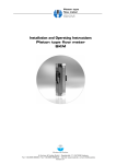
PORTABLE ULTRASONIC FLOWMETER
EESIFLO PORTALOK 7S
PORTALOK 7S ULTRASONIC FLOW METER USER MANUAL
USER'S MANUAL
IM-EESIFLO
ELECTRONICS EDITION JAN 2007
Measuring Worldwide
PORTALOK 7S ULTRASONIC FLOW METER USER MANUAL
USER'S MANUAL
IM-EESIFLO
Measuring Worldwide
ELECTRONICS EDITION JUL 2007
Introduction
Regarding this Manual
This manual has been written for the personnel operating EESIFLO Portalok 7S series flowmeter. It
contains very important information about the instrument, how to handle it correctly, how to avoid
damaging it and how to avoid injury. Always keep this manual at hand. Get acquainted with the
safety rules and the handling precautions. Make sure you have read and understood this manual
before using the instrument. All reasonable effort has been made to ensure the correctness of the
content of this manual. Should you however find some erroneous information, please inform us.
Please note that we shall be grateful for any suggestions and comments regarding this product.
This will ensure that we can further improve our products for the benefit of our customers and in the
interest of technological progress.
Should you have any suggestions about improving the documentation and particularly this User's
Manual, please let us know so that we may consider your comments for future reprints.
We also provide special customer solutions and will be pleased to advise you in using EESIFLO for
specific applications and finding the most appropriate solution for your measurement problem.
Please log onto our website www.eesiflo.com for contact details.
The content of this manual may be changed without prior notice. All rights reserved. No part of this
manual may be reproduced in any form without EESIFLO's written permission.
Safety Precautions
This manual contains the following safety information:
Note:
The notes contain important information which help you use your instrument in an optimal
way.
Attention!
This text gives you important instructions which should be followed in order to avoid
damage or destroy the instrument. Proceed with attention!
This text denotes an action which could result in injury or death of personal. Proceed
cautiously!
Follow these safety precautions!
PORTALOK 7S ULTRASONIC FLOW METER USER MANUAL
USER'S MANUAL
IM-EESIFLO
Measuring Worldwide
ELECTRONICS EDITION JUL 2007
Warranty
The EESIFLO Portalok 7S series flowmeter is guaranteed for 12 months from date of purchase
provided the equipment has been used for the purpose for which it has been designed and operated
according to the instructions given in the present User's Manual. Misuse of the EESIFLO meter will
immediately revoke any warranty given or implied. This includes:
• the replacement of a component of the EESIFLO by a component that was not authorized by
EESIFLO;
• Unsuitable or insufficient maintenance;
• Repair of the EESIFLO by unauthorized personnel.
EESIFLO assumes no responsibility for injury to the customer or third persons caused by the
material owing to defects in the product which were not predictable or for any indirect damages.
The EESIFLO Portalok 7S series is a very reliable instrument. It is manufactured under strict quality
control, using modern production techniques. If installed correctly,as recommended, the Portalok 7S
will be an invaluable tool for flow measurement. If you are unable to resolve any technical issues
with the help of this manual, please contact our office, giving a precise description of the problem.
PORTALOK 7S ULTRASONIC FLOW METER USER MANUAL
USER'S MANUAL
IM-EESIFLO
Measuring Worldwide
ELECTRONICS EDITION JUL 2007
The Portalok 7S Flowmeter
Overview
EESIFLO Portalok 7S is a flowmeter that uses ultrasonic signals to measure the flow in pipes or
conduits filled with liquid. It can measure the following quantities:
- flow velocity;
- volume and total flow;
- sound velocity of a medium.
The transducer’s recommended temperature operation is between -30°C and 100°C and for short
periods,up to 130°C. Measurement can be made on all commonly used pipe materials such as steel,
synthetic material, glass or copper. Recommended pipe diameters may range from 1 inch (25mm) up
to 40 inches (1000 mm) with the standard transducers.The two clamp-on transducers allow for noninvasive measurement that does not affect the pipework or the liquid to be measured. They are small,
lightweight and easy to install.
PORTALOK 7S is a poratable ultrasonic flow meter.and operates with an external power supply
100...240 VAC or 6 VDC internal batteries. The Portalok 7S is a waterproof flow meter and has a
protection degree IP68 when its cover is closed .It is therefore suitable for monitoring tasks under
difficult environmental conditions.
Portalok 7S has a backlit display which shows input data and measurement results as well as
operational errors. The menus guide the user through the parameter setup and the measurement.
An internal data bank contains the properties of many materials and media which may be selected to
suit the application.
PORTALOK 7S ULTRASONIC FLOW METER USER MANUAL
USER'S MANUAL
IM-EESIFLO
Measuring Worldwide
ELECTRONICS EDITION JUL 2007
Measuring Principle
EESIFLO uses ultrasonic signals for the measurement of liquid flow, employing the so-called transit
time method. Ultrasonic signals are emitted by one transducer installed on on a pipe, reflected on the
opposite side and received by a second transducer. These signals are emitted alternatively in the
direction of flow and against the flow
Transit path of the ultrasonic signals
When the medium is flowing, the transit time of the sound signals propagating in the direction of flow
is shorter than the transit time of the signal propagating against the direction of flow.
The transit-time difference ∆T is measured and allows the determination of the average flow velocity
on the propagation path of the ultrasonic signals. A profile correction is then performed to obtain the
average flow velocity on the cross-section of the pipe, which is proportional to the volume flow rate.
PORTALOK 7S ULTRASONIC FLOW METER USER MANUAL
USER'S MANUAL
IM-EESIFLO
Measuring Worldwide
ELECTRONICS EDITION JUL 2007
The Portalok 7S diagnoses the incoming ultrasonic signals and evaluates the plausibility of the
measured values. The integrated microprocessors control the complete measuring cycle, eliminating
disturbance signals by statistical signal processing techniques.
Portalok 7S Applications
The Portalok 7S can be used where the pipe wall and the liquid to be measured are sonically
conductive. This is true for pipe walls consisting of homogeneous material, and for liquids which carry
only small amounts of solid particles or gas bubbles. Since ultrasonic waves also propagate in solid
materials, the transducers can be mounted outside the pipe, allowing for non-invasive measurement.
The transit time difference effect can be observed over the complete range of flow velocities found in
many applications. Furthermore, it is independent of the electrical parameters of the fluid (conductivity,
dielectric constant, etc.). The Portalok 7S is thus a very versatile instrument.
Advantages:
• Non-invasive method permits safe measurement on aggressive or high temperature media flowing
in closed conduits.
• Flow values can be measured without interruption of the process.
• The installation does not require any alterations to the pipe system.
PORTALOK 7S ULTRASONIC FLOW METER USER MANUAL
USER'S MANUAL
IM-EESIFLO
Measuring Worldwide
ELECTRONICS EDITION JUL 2007
Description of the Flowmeter
Control Panel of the Portalok 7S
Attention!
The protective degree IP68 is only effective when the meter lid is fully shut.
Crushproof, waterproof case,
IP68 rating when closed
Battery charging status
Available free points for
datalogging
Serial port
Break operation
Top panel of Portalok 7S - Batteries are located inside the unit.
They can be accessed and replaced by removing the top panel.
See labels
for transducer connection
See labels for
output connection
See labels for
power supply connection
PORTALOK 7S ULTRASONIC FLOW METER USER MANUAL
USER'S MANUAL
IM-EESIFLO
Measuring Worldwide
ELECTRONICS EDITION JUL 2007
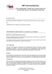
The Transducers
The transducers are mounted correctly if the engravings on the two transducers together form an
arrow. The transducer cables should then show in opposite directions.
The arrow, in conjunction with the displayed measured value, will help you to determine the direction
of flow.
Correct positioning of the transducers with the arrow in the direction of the flow
Note:
The engraving should also form an arrow if the two transducers are mounted on
opposite sides of the pipe wall.
Serial Number
Model and serial number are indicated on the lid-cover in the flowmeter. When contacting EESIFLO,
always have both numbers at hand. If the serial number is lost, the number can be obtained from the
start up screen.
Handling
Scope of Delivery
On delivery, please make sure that all items of the following list (standard scope of delivery) are in the
package:
1
User's manual
1
Portalok 7S in IP 68 case including power supply and cable (output cable is optional)
1
Set of 2 transducers as per order, with integrated cables
2
Transducer mounting fixtures with tension straps/chains
1
Tube of acoustic coupling compound
Your package may contain other components according to your particular order.
Model designation and serial number are given on the data plate of the flowmeter. When contacting
EESIFLO, always have both of them at hand,
General Precautions
The Portalok 7S is a precision measuring instrument and it must be handled with care. To obtain good
measurement results and in order not to damage the instrument, it is important that attention is paid to
the instructions given in this User's Manual, and particularly to the following points:
• Protect the instrument from excessive shock.
• Keep the transducers clean.
• Do not drop transducers from heights
• The protective degree IP68 of Portalok 7S is given only if the lid is closed
• Connect the flowmeter correctly to the mains power supply if not using battery power
• Work under correct ambient conditions (see specifications). Do not exceed IP 68 protection.
Maintenance
No maintenance work is necessary. Always follow the handling precautions and the instructions given
in this manual. The Portalok 7S will provide trouble free service if installed correctly, in an appropriate
location and used as recommended.
Cleaning
Clean the instrument with a soft cloth. Do not use detergents. Remove traces of acoustic coupling
compound from the transducers with a paper tissue.
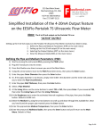
Installation of EESIFLO the Portalok 7S
Location
, STEP 1 :Select the measuring point according to the recommendations given in this manual.
Ensure that the temperature at the selected location is within the operating temperature range of the
transducers.
STEP 2, Select a location that is within cable reach from the measuring point to the transmitter.
Ensure that the temperature at the selected location is within the operating temperature range of the
transmitter.
Setting-up
Connection of the Transducers
Attention!
The IP 68 protective degree of the flowmeter is only guaranteed if all cables are
connected firmly and tightly to the weatherproof connectors on the flowmeter. The top
plate should be tightly screwed to the housing.
Connection of the power supply and Battery Charging
110/VAC or 220/VAC – Do not connect the meter to incorrect voltages when charging.
The Portalok 7S will run approximately 24 hours on battery power when fully charged. Do not
overcharge the unit. 24 hours usage will require approximately 24 hours charging time.
The Portalok 7S has two status LED’s which display status information about the battery and the
battery charging process.
BATTERY LED has three states:
ON – The charge of the battery is more than 20 percent but less than 50 percent.
OFF – The charge of the battery is more than 50 percent.
BLINKING – The charge of the battery is less than 20 percent.
CHARGE LED also has three states:
ON – The instrument is connected to a power supply. The battery is fully charged.
OFF- The instrument is not connected to a power supply. The battery is not being charged.
BLINKING- The instrument is connected to a power supply. The battery is being charged.
BATTERY REPLACEMENT PROCEDURE
Replacing the battery requires careful removal of the control panel cover screws and panel.
Please note the following:
ONLY USE BATTERY PACKS SUPPLIED BY EESIFLO TO ENSURE GUARANTEED
PERFORMANCE AND TO AVOID DAMAGE TO THE INSTRUMENT.
Connection of the Process Outputs
Attention!
The IP 68 protective degree of the flowmeter is only guaranteed if all cables are
connected firmly and tightly to the weatherproof connectors on the flowmeter. The top
plate should be tightly screwed to the housing.
The optional output connector to send signals to remote devices consists of a cable with 6 flying leads.
Each lead has been numbered. Please refer to the table for information for wiring purposes.
Labels for the connection of the process outputs
Connection
Binary output B1
Binary output B2
Current loop I1
If you have purchased an optional output cable, please refer to the labels attached to the actual cables for
identification.
Circuits of the process outputs
OUTPUT
EESIFLO
CIRCUIT
+
Current loop
(active)
RLOAD < 500 Ω
mA
+ -
Binary output
(OpenCollector)
UH = (5 to 24) V
+
-
Binary output
(ReedContact
Relay)
RC[kΩ] = UH / Ic [mA]
RC
+
V
-
UH
Ic = (1 to 4) mA
UMAX = 24 V
a
IMAX = 150 mA
b
A
(optional and
not standard)
B
+
RS485
(one 120Ω termination
resistor)
NOT APPLICABLE IN
THIS VERSION
Getting Started- Instrument Start-Up
Turn power on by pressing PWR, a message EESIFLO
will appear for several seconds along with the serial
number of the instrument..
Note!
No data can be entered whilst the serial number is displayed.
On start up the >Par< (Parameter) mode is indicated
If you have previously been doing measurements the
>mea< ( Measurement) screen will appear.
The Keyboard
The operator interface of the Portalok 7S consists of 6 keys including power switch
Keyboard of EESIFLO Portalok 7S
Key operations
General functions
Power and the backlight are controlled by the PWR power button. To switch the instrument ON,
briefly press the PWR button. To switch the backlight on and off, press the PWR button briefly. To
switch the instrument OFF, press the PWR button for at least 3 seconds.
Confirm selection or entered value.
Cancel selection or edition and return to the main menu. Similar to Esc and is
used at any time a wrong entry is made
RESET: Press these keys simultaneously to recover from an error.
This has the same effect as restarting the unit.Similar to Ctrl, Alt Del
Data will not be affected.
UNIT (cold-start): Pressing these keys simultaneously while switching the
flowmeter ON until the MAIN MENU appears will initialize EESIFLO. Most
parameters and settings are reset to the factory default values. The memory will
not be cleared.
Horizontal selection
Select next item on the right (wrap after rightmost item).
Select next item on the left (wrap after leftmost item).
Vertical selection
Scroll forward (wrap after last item).
Scroll backward (wrap after first item).
Input of numerical values
Move cursor to the right.
Scroll digit above cursor.
Move cursor to the left. When the cursor is on the left margin:
- an already edited value will be reset to previously saved value
- an unedited value will be deleted.
If the entered value is not valid, an error message will be displayed. Press any
key and enter a correct value.
Input of text
Move cursor to the right (wrap after rightmost item).
Scroll through character set above cursor.
Reset all characters to last saved entry.
The Menus
The Main Menu
After switching on and initialization, the main menu
appears on the first line of the display. The main menu
has following entries: PAR (parameter), MEA
(measuring), OPT (output options) and SF (special
functions), corresponding to the four different program
branches. The selected program branch is displayed in
capital letters between arrows. The full name of the
program branch is displayed on the second line.
Use keys
and
to select a program branch.
Confirm your selection by pressing ENTER.
The Program Branches
In the PARAMETER program branch, you can enter the parameters of the pipe and of the medium.
The MEASURING program branch leads you through the different steps of the measuring process.
In the OUTPUT OPTIONS branch, you can set all relevant output parameters, such as the physical
quantity to be displayed during measurement and the measurement units.
The SPECIAL FUNCTION branch contains all functions that are not directly related with the basic
measurement.
If a vertical arrow (Ú) is displayed beside a menu
option, this menu option contains a scroll list. This list is
displayed on the second line.
Use the arrow keys
and
to scroll through the
list, then confirm your selection by pressing ENTER.
Portalok 7S sometimes requests a selection on the
second line. The selected option is displayed in capital
letters between arrows.
Use keys
and
to select one of the options,
then confirm your selection by pressing ENTER.
The Portalok 7S sometimes requests a horizontal
selection between different menus on the upper line of
the display. The selected menu is displayed in capital
letters between arrows. The selected options of the
menus are displayed on the second line.
Use key
to select one of the menus.
Use the arrow key
menu.
to scroll through the selected
Note:
You can return to the main menu at any time by pressing key
Note:
(Esc)
In this manual, all program entries and keys will appear in capital letters. Program entries
are in typewriter characters ("PARAMETER"). Submenus are separated from the main
menu entry by a backslash.
Command Execution during Measurement
Commands that can be executed during measurement are shown on the upper line of the display. A
command line always begins with a Æ. Scroll on the upper line of the display with key
until the
required command is displayed. Confirm your selection with ENTER. Depending on the instrument's
settings, an authorization code might have to be entered; example - the user is required to use the
instrument outside of its recommended measurement range. A list of the commands available during
measurement is given in the HOT CODE section.
HotCodes
A HotCode is a specific key sequence which has to be entered to activate special settings. The
Portalok 7S is a very powerful instrument but certain settings are purposely locked to avoid
misapplication in the field.
To enter a HotCode, select the program branch >Sf<
SPECIAL
FUNCTIONS\SYSTEM
SETTINGS\
MISCELLANEOUS.
Select YES to enter a HotCode.
Use HotCodes only when instructed by EESIFLO for
certain applications
Enter the required HotCode. Confirm with ENTER.
If an invalid code is entered, an error message is
displayed. Press any key to continue.
Select YES to continue or NO to go back to the
MISCELLANEOUS menu.
Interruption of Power
EESIFLO stores the last measurement parameters in a non-volatile coldstart resistant EPROM as
soon as the measurement begins.
Previous input data ad measuring parameters are preserved.
EESIFLO
EESXXXX-00000999
If the unit is accidentally turned off, the serial number of the
instrument appears briefly on the display when the power is
restored
The Portalok 7S automatically continues the measurement when power is restored.. All selected
output options will also be active.
The flowmeter does not continue the measurement after return of the power supply if a coldstart was
performed.
To perform a coldstart, press BRK, C and ENTER simultaneously, then let the BRK and C keys
pressed and release only the ENTER key. The instrument will be restarted. Do not release BRK and
C before the main menu is displayed.
Selection of the Measuring Point
The correct selection of the measuring point is crucial for achieving reliable measurements and a high
accuracy. Measurements must take place on a pipe where:
• Sound can propagate and in which a fully developed rotationally symmetrical flow profile is
observed .
The correct positioning of the transducers is essential for error-free measurement. It guarantees that
the sound signal will be received under optimal conditions and evaluated correctly. Because of the
variety of applications and the different factors influencing measurement, there can be no standard
solution for the positioning of the transducers. The correct position of the transducers will be
influenced by the following factors:
• the diameter, material, lining, wall thickness and form of the pipe;
• the medium flowing in the pipe;
• the presence of gas bubbles in the medium.
Ensure that the temperature at the selected location is within the operating temperature range of the
transducers
Select the location of the instrument within cable reach of the measuring point. Ensure that the
temperature at the selected location is within the operating temperature range of the transmitter.
Acoustic Propagation
Acoustic propagation can be assumed when pipe and medium do not attenuate the sound so strongly
that the signals are completely absorbed before reaching the second transducer. The level of sound
attenuation in a specific system depends on:
• the kinematic viscosity of the liquid,
• the proportion of gas bubbles and solid particles in the liquid,
• the presence of deposits on the inner pipe wall,
• the wall material.
• Temperature
Ensure that following conditions are fulfilled at the measuring point:
• the pipe is always full
• no material build up.
• no bubbles accumulate (even bubble-free liquids can form gas pockets where the liquid expands,
e.g. especially after pumps and where the cross-sectional area of the pipe is not uniform).
Undisturbed Flow Profile
Many flow elements (elbows, slide valves, valves, pumps, T-sections, reducers, diffusers, etc.) distort
the flow profile in their vicinity. The axi-symmetrical flow profile required for correct measurement may
therefore influence flow measurements. A careful selection of the measuring point will reduce the
impact of disturbance sources.
It is most important that the measuring point is chosen at a sufficient distance from any
disturbance sources. Only then can it be assumed that the flow profile in the pipe is fully
developed.
The Portalok 7S will however provide good results even under non-ideal measuring conditions.
In the following examples, recommended straight inlet and outlet pipe lengths are given for different
types of flow disturbance sources to assist in selecting the correct measuring point. This may not
always be possible but should be used as a guide.
Recommended distance from disturbance source:
(D = nominal pipe diameter at measuring point, L = recommended distance)
Disturbance source: 90°-elbow
Inlet
L ≥ 10 D
Outlet
L≥5D
Disturbance source: 2 x 90°-elbows in one plane
Inlet
L ≥ 25 D
Outlet
L≥5D
Disturbance source: 2 x 90°-elbows in different planes
Inlet
Outlet
L ≥ 40 D
L≥5D
Disturbance source: T-section
Inlet
L ≥ 50 D
Outlet
L ≥ 10 D
Disturbance source: diffuser
Inlet
L ≥ 30 D
Outlet
L≥5D
Disturbance source: reducer
Inlet
L ≥ 10 D
Outlet
L≥5D
Disturbance source: valve
Inlet
L ≥ 40 D
Outlet
L ≥ 10 D
Disturbance source: pump
Inlet
L ≥ 50 D
Points to Avoid
Avoid measuring locations:
• in the vicinity of deformations and defects of the pipe;
• or in the vicinity of welding;
•
where deposits have formed in the pipe ie: lime scale, calcium build up..
Points to avoid
For an horizontal pipe:
Select a location where the transducers can be mounted on the side of the pipe, so that the
sound waves emitted by the transducers propagate horizontally in the pipe. Thus, the solid
particles deposited on the bottom of the pipe and the gas pockets developing at the top won't
influence the propagation of the signal.
Correct
Incorrect
For a free inlet or outlet pipe section:
Select the measuring point at a location where the pipe cannot run empty.
Correct
Disadvantageous
Correct
Disadvantageous
For a vertical pipe:
Select the measuring point at a location where the liquid flows upward. The pipe must be
completely filled.
Correct
Incorrect
Basic Measurement
Once the measuring point has been selected, the parameters of the pipe and of the medium can be
entered. They can be modified at any time later by pressing B and then accessing PARAMETER again.
Input of the Pipe's Parameter
The parameters of the pipe now have to be entered for every measuring point.
The values that can be given to the parameters of pipe
and medium are limited by the characteristics of
transmitter and transducers. Refer to the Portalok
specifications if you are not sure of these limits.
(Example)
Note:
In some instances the entered outer diameter may be
too big. In this case, the instrument might display the
maximal possible value for this parameter (1100.0 mm
in the case of standard transducers and a pipe with a
wall thickness of 50 mm).
The Portalok 7S only accepts the parameters if all the values have been entered in
PARAMETER .
The pipe parameters that you will now enter can be modified at any time in PARAMETER.
In the main menu by pressing B, select the program
branch PARAMETER and press ENTER.
Pipe Outer Diameter / Circumference
Enter the outer diameter of the pipe.
Confirm your entry or the displayed value by pressing
ENTER.
It is possible to change this menu in order to enter the pipe circumference instead of the diameter.
This setting is coldstart resistant and can be made in the program branch SPECIAL FUNCTION
If the input of the pipe circumference is activated and you inadvertently enter a 0 (zero) in the OUTER
DIAMETER display, the Portalok 7S will switch to the PIPE CIRCUMFER. display. If you do not wish to
enter the pipe circumference, press B to return to the main menu and start the parameter input again.
Wall Thickness
Enter the pipe wall thickness. The range of possible
values depends on the transducer specifications.
Default value for this parameter is 3.0 mm.
Confirm by pressing ENTER.
If you do not have reliable wall thickness information
from known pipe specifications, you may need to
measure the wall thickness on site with a non contact
thickness gage.
If you do not have a separate pipe wall thickness gage,
please contact EESIFLO for the model WTG-EES-01
stand alone ultrasonic thickness gage or purchase one
from a local vendor.
Note:
The Portalok calculates the inner diameter (outer diameter - 2 x wall thickness) and
checks if this value is within the specified inner diameter range for the transducers used.
An error message is displayed if this is not the case. It is possible to modify the value of
the minimal pipe inner diameter accepted by the Portalok 7S for a certain type of
transducer. Contact EESIFLO for the HOTCODE
Pipe Material
The pipe material now has to be selected in order to determine its sound velocity. The nominal sound
velocities of the materials of the selection list are already programmed in the instrument. When the
pipe material is selected, the Portalok 7S sets the sound velocity automatically.
Select the pipe material in the pipe material selection
list. If the correct material is not listed, select the entry
OTHER MATERIAL.
Confirm by pressing ENTER.
Note:
It is possible to select which materials are to be displayed in the material selection list..
If you have selected OTHER MATERIAL, the Portalok
7S requests the entry of the sound velocity. Enter the
sound velocity of the pipe material. Values between
600.0 and 6553.5 m/s are accepted. Confirm by
pressing ENTER.
Important!
Enter the sound velocity of the material (longitudinal velocity or transversal velocity)
which is nearer to 2500 m/s.
Pipe Lining
If the pipe is lined, select YES and confirm by pressing
ENTER.
If you select NO, the Portalok 7S displays the next
parameter
Select the lining material or the entry
MATERIAL if the lining material is not listed.
OTHER
Confirm by pressing ENTER.
Note:
It is possible to select which materials are to be displayed in the material selection list.
Contact EESIFLO if you wish to have this when ordering.
If you have selected OTHER MATERIAL, the Portalok
7S requests the entry of the sound velocity. Enter the
sound velocity for the liner material. Values between
600.0 and 6553.5 m/s are accepted.
Confirm by pressing ENTER.
Enter the pipe liner thickness. Default value for this
parameter is 3.0 mm.
Confirm by pressing ENTER.
Note:
EESIFLO checks the correlation between the entered outer diameter, the pipe wall and
liner thickness. The inner diameter (outer diameter - 2 x wall thickness - 2 x liner
thickness) should be within the specified inner diameter range for the transducers used.
An error message is displayed if this is not the case.
Pipe Roughness
The roughness of the inner pipe wall influences the flow profile of the liquid and is used for the
calculation of the profile correction factor. In most cases, the pipe roughness cannot be exactly
determined, but must be estimated. For your convenience, we have compiled a list of roughness
factors for a number of materials, based on experience and measurements. The display ROUGHNESS
requests the input of a value for the selected pipe or lining material.
Change the suggested value according to the condition
of the inner pipe wall. Values between 0.0 mm and 5.0
mm are accepted. Default value is 0.1 mm.
Confirm by pressing ENTER.
Input of the Medium's Parameters
After entering the pipe parameters, the Portalok 7S requests the medium parameters.
The medium parameters required for measurement are:
•
•
•
•
the minimum and maximum sound velocity for the medium,
the kinematic viscosity of the medium,
the density of the medium (only if the output option MASS FLOW is activated),
the temperature of the medium.
Select the medium or the entry OTHER MEDIUM if the
medium to be measured is not listed.
Confirm by pressing ENTER.
If the medium has been selected, the Portalok 7S will immediately request the medium temperature. If
you have selected OTHER MEDIUM, EESIFLO requests the entry of the minimal and maximum sound
velocity, the kinematic viscosity and the density of the medium.
Note:
It is possible to select which media are to be displayed in the medium selection list.
Sound Velocity
EESIFLO uses the sound velocity of the medium for the calculation of the distance between the
transducers at the beginning of the measurement. However, the sound velocity does not influence the
measuring result directly. Often, the accurate value of the sound velocity for a given medium is unknown. A range of possible values for the sound velocity must therefore be entered.
Enter the minimum and maximum values of the sound
velocity for the medium you want to measure (in m/s).
Values between 800.0 m/s and 3500.0 m/s are
accepted.
Confirm your entries by pressing ENTER.
Kinematic Viscosity
The kinematic viscosity influences the flow profile of the liquid. The Portalok 7S uses the value of the
kinematic viscosity as well as other parameters for the profile correction.
Enter the kinematic viscosity of the medium. Values
between 0.01 and 30,000.00 mm2/s are accepted.
Confirm by pressing ENTER.
Density
EESIFLO now requests the density of the medium. This value is required for calculating the mass flow
rate (= volume flow rate multiplied with the entered density).
Note:
If you are not interested in measuring the mass flow rate, just confirm the displayed value
by pressing ENTER. This will not influence your results.
Enter the density of the medium. Values between 0.10
g/cm3 and 20.00 g/cm3 are accepted.
Confirm by pressing ENTER.
Medium Temperature
EESIFLO requires the medium temperature for the calculation of the distance between the
transducers (distance suggested at the beginning of measurement) and for correcting the sound
velocity and the viscosity which both depend on temperature.
Enter the medium temperature. The value must be
within the operating range of the transducer. The
default value is 20°C.
Confirm by pressing ENTER.
Note:
The range of possible medium temperature depends on the operating range of the
selected transducers.
Other Parameters
Transducer Parameters
The following display will appear at the end of parameter input:
Select STANDARD to work with standard transducer
which is part of the Portalok 7S standard offering or
enter parameters or SPECIAL VERSION to edit the
transducer parameters (manufacturer's data must be
available).
Confirm by pressing ENTER.
Attention!
EESIFLO cannot guarantee the precision of values obtained when working with
transducers not designed for the model purchased. Measurement might be impossible.
If you have selected SPECIAL VERSION, Portalok 7S
will ask for the transducer data. Enter the value of the 6
transducer parameters as given by the manufacturer,
confirming each entry by pressing ENTER.
Cable length
Portalok 7S then asks for the length of any additional
transducer cable used (not the total length of the
transducer cable!). Enter the additional cable length if
non standard extra lengths have been supplied and
confirm by pressing ENTER.
You will only need to use this if you have purchased
additional cable lengths
Selection of the Sound Path Factor
In the main menu, select the program branch
MEASURING, then press ENTER.
If this error message appears, “no complete parameter
set exists” Return to the program branch PARAMETER
and enter the missing parameters.
EESIFLO now requests the sound path factor, which is the number of transits of the ultrasonic waves
through the medium in the pipe.
A sound path factor of "0" (zero) is not feasible in terms of physics.
An odd number of transits (diagonal mode) require mounting of the transducers on opposite sides of
the pipe (see illustration below).
An even number of transits (reflection mode) requires mounting of the transducers on the same side
of the pipe (see illustration below).
Some small pipes in sound path 1 may show a negative distance. In this case, the transducers must
overlap according to the negative distance.
An increased number of transit paths mean increased accuracy of the measurement. However, the
increased transit distance also leads to a higher attenuation of the signal. The reflections on the
opposite pipe wall and eventual deposits on the inner pipe wall cause additional amplitude losses of
the sound signal. Measurements on a system where both the pipe and the medium strongly attenuate
the signal may require fewer sound path transits.. The signal may by further attenuated by deposits
on the inner pipe wall,resulting in a single (1) transit
Transducer installation
in diagonal mode
number of transits
sound path
Transducer installation
in reflection mode
number of transits
1
2
3
4
etc.
etc.
sound path
Sound path
Note:
Positioning the transducers is easiest for even numbers (2,4,6 etc )of transit paths than
for odd numbers(1,3,5 etc)
Tip: Select sound path 2 as this is is the most convenient and quickest to get started.
Enter the sound path factor.
Confirm by pressing ENTER.
Mounting and Positioning the Transducers
Distance between the Transducers
A
‘Refle’
'Diago'
Note:
= Measuring channel A
= Reflection mode
= Diagonal mode
Once the number of transit paths has been entered, the
Portalok 7S indicates the mounting distance between
the transducers.(here: 54 mm). The transducer
distance given here is the distance between the inner
edges of the transducers. For very small pipes, a
negative transducer distance is possible
The accuracy of the distance suggested by EESIFLO depends on the accuracy of both
the pipe and medium parameters entered.
Transducer distance
Mounting the Transducers
Always mount the transducers so that the front edges
are opposite to each other. The engraving on the top
of the transducers should form an arrow, as illustrated.
Correct positioning of the transducers
Important!
In order to obtain maximum acoustics between the pipe and the transducers,
check the following:
•
Rust or other deposits absorb the sound signals! Clean the pipe where you plan to
mount the transducers. Remove rust or loose paint. Grind off any thick layer of paint.
•
Always apply a bead of acoustic coupling compound lengthwise down the center of
the contact surface of the transducers.
• There should be no air or air pockets between the transducer surface and pipe wall.
Ensure that the mounting fixture applies sufficient pressure on the transducers.
Mounting with Spring Tension Fixtures (optional)
Note:
Where vibration is high, we recommend the optional EESIFLO tension straps. Most
applications use standard spring and chain sets which are provided. These chain sets
also allow for pipe expansion or contraction.
Note:
Do not tighten the screws completely at this point!
-60
0 mm10
20
30
0
50
60
70
80
90
10
110
120
320
330
Transducers mounted with tension straps
Mounting with Runners and Chains (Slide rail option)
• Insert the transducers in the runners. Turn the screw on top of the runners by 90° in order to
engage and lock its extremity in the groove of the inserted transducer.
• Insert the ruler in the lateral slots of the runners. Adjust the transducer distance suggested by the
Portalok 7s and fix the transducers with the small plastic screws on the transducer cable side of the
runner.
-60
0 mm10
20
30
0
50
60
70
80
90
10
110
120
320
330
Transducers mounted with runners and chains (optional)
• Place the runners/ruler assembly on the pipe at the measuring point.
• Insert the last ball (spring end of the ball chain) in the slot on the top of one of the clips.
• Lay the chain around the pipe
Note:
When mounting the transducers on a vertical pipe with the Portalok 7S situated lower
than the pipe, it is recommended to slip the cable of the upper transducer under the
tension strap in order to free it from mechanical strain.
• Pull the chain firmly against the spring tension and insert it in the second slot on the top of the
runner.
• Fix the other transducer in the same way.
Extension of the Ball Chain
To extend the chain, insert the last ball of the spring end of the extension in the fastening clip of the
ball chain.
The spare fastening clips supplied with the chain can be used to repair a broken chain.
Positioning the Transducers
When the transducers are mounted, confirm the
transducer distance by pressing ENTER.
A bar graph ("S=") informs you of the amplitude of the
received signal.
Adjust the transducers by moving them slightly in order
to obtain a maximal length of the bar graph.
Press key
to scroll to the lower line of of the
display.The bar graph Displays the quality of the signal
("Q="). If the signal is not sufficient for measurement,
UNDEF is displayed.
Press key
to scroll to the upper line of the
display.The bar graph displays the signal amplitude
("S=") The display also indicates the transit time in
microseconds.
Note:
It is important that the maximum signal with the shortest transducer distance (shortest
transit time) is achieved. However, this signal maximum should not deviate from the
suggested distance by more than ± 0.5 cm (50 mm). Should deviations exceed 50mm
check entered parameter inputs or repeat measurement at a different location on the
pipe.
After positioning of the transducers, the suggested
transducer distance is again requested with “?”.
Enter the actual (precise) transducer distance and
press ENTER or just confirm the displayed value (if
within 50 mm) by pressing ENTER.
Starting the Measurement
When the precise transducer distance has been entered, the measurement will be automatically
activated. You may have to wait a few seconds after pressing the last enter before the unit will display
the flow readings.
You can press ENTER to return to the bar graph
display.
The results are displayed and transmitted according to the selected output options
Recognition of Flow Direction
The medium flows in direction of the arrow if the display shows a positive flow reading (example:
54.5 m3/h).
The medium flows against the arrow direction if the display shows a negative flow reading
(example: -54.5 m3/h).
The transducers are mounted correctly if the engraving on the two transducers together form an
arrow. The transducer cables should then show in opposite directions.
The arrow, in conjunction with the displayed measured value, will help you to determine the direction
of flow.
Stopping the Measurement
You can stop the measurement at any time by pressing B
Attention!
Be careful not to interrupt an ongoing measurement by inadvertently pressing B
Displaying the Measured Values
The physical quantity to be measured, stored and transmitted can be set in the OUTPUT OPTIONS
Default display is quantity of measurement displayed on the first line and its value on the second line.
It is possible to temporary adapt the display to your requirements by selecting which quantity should
be shown on the first and second line of the display.
Selection of the Physical Quantity and of the Unit of
Measurement
The Portalok 7S can measure the following quantities:
• flow velocity
• volume flow rate
• mass flow rate
The Portalok 7S measures the flow velocity directly. The volume flow is calculated by multiplying the
flow velocity with the cross-sectional area of the pipe, the mass flow by multiplying the volume flow
with the density of the medium.
In the main menu, select >OPT< OUTPUT OPTIONS.
Select quantity of measurement in the scroll list.
Confirm by pressing ENTER.
The selection of the physical quantity SOUND VELOCITY immediately ends the OUTPUT OPTIONS,
since the process outputs are not active during the measurement of the sound velocity and there are
thus no more settings to be made.
For all quantities of measurement other than SOUND
VELOCITY, a scroll list of the available measurement
units is displayed. The previously selected unit is shown
on the second line. Select the unit of measurement ie
“Volume” then the physical quantity “m3/h” to be
displayed and transmitted..
Confirm by pressing ENTER.
You can now return to the main menu by pressing BRK. The next displays of the program branch
OUTPUT OPTIONS are for the activation of the output options.
Configuration of the Display
The Portalok 7S has the option of displaying two of the measured values (one on each line of the
display) the display readings may be configured according to your requirements.
You can change the displayed values independently and without interfering with the ongoing
measurement. The changes have no influence on the totalizers, the storage of measured values, the
operation of the process interfaces etc.
The following can be displayed on the first line of the display:
• Designation of the quantity of measurement actually being measured and recorded
• Totalizer values (if activated)
• the date and time at which the memory will be full
• the measuring mode
• the transducer distance
• the calculation function if activated
• the time remaining until the automatic stop of a programmed measurement
• the state of the alarms if any alarm outputs are activated and the display of the alarms' state is
enabled.
The following information can be displayed on the second line in addition to the selected quantity of
measurement:
• Flow velocity
• Mass flow rate
• Volume flow rate
Use key
to scroll through the different displays of the first line whilst measurement is on.
Use key
to scroll through the different displays of the second line while measurement is on.
The asterisk "*" indicates that the displayed value (here:
the flow velocity) is not the selected quantity of
measurement (here: the volume flow).
Transducer Distance
During measurement, it is possible to scroll to display
the transducer distance by pressing the
key.
The actual optimum transducer distance “L” is displayed
first in parenthesis (here: 51.2 mm), then the entered
transducer distance (here: 50.8 mm). The optimal
transducer distance might change during measurement
due to temperature fluctuations for example. An
eventual
mispositioning
of
the
transducers
(here: -0.4 mm) will be internally compensated by the
Portalok 7S.
Attention!
Never change the transducer distance during measurement!
Datalogging and Retrieving Data
By Scrolling through the OUTPUT OPTIONS menu, you will be prompted to save data.as well as the
data storage rate The built in datalogger will normally have 60,000 values available for data storage.
To retrieve data, connect the serial cable(Null Modem) supplied with the unit to the Portalok 7S.Use
the EESIDATA program (provided) to retrieve data onto your computer. Ensusre that the com port
settings are correct. EESIDATA will allow you to view stored values, study readings in depth and also
prepare the data in graphical format for saving or printing.
Advanced Measuring Functions
Command Execution during Measurement
Commands that can be executed during measurement are shown on the upper line of the display. A
command line always begins with a Æ.
Scroll on the upper line of the display with key
until the required command is displayed. Confirm
your selection with ENTER. Depending on the instrument's settings, an authorization code might have
to be entered. The commands available are the following:
Commands that can be executed during measurement
COMMAND
ACTION
ÆADJUST SENSORS
Switch to the sensor positioning mode. If a program code is
activated, measuring will be automatically continued 8 seconds
after the last keyboard action.
ÆCLEAR TOTALIZER
All totalizer values will be reset to zero.
ÆBREAK MEASURE
Stop measuring and return to main menu. If a program code is
activated, you have to enter the 6 digit BREAK-CODE first.
The Damping Factor
Each measured value displayed by the instrument is actually the average of the measured values of
the last x seconds, where x is the damping factor. A damping factor of 1 s means that the measured
values are not averaged, since the measuring rate is of approx 1 value per second. The default value
is 10 s. This is appropriate for normal flow conditions. Strongly fluctuating readings caused by high
flow dynamics require a larger damping factor.
Select the OUTPUT OPTIONS.Scroll through the list, confirming the already selected options by
pressing ENTER, until you reach the DAMPING option.
Enter the damping factor. Values between 1 s and
100 s are accepted.
Confirm by pressing ENTER.
Rreturn to the main menu by pressing BRK.
Flow Totalizers
The Portalok 7S totalizes the volume or the mass of medium passing through the pipe at the
measuring point.
• There are two built-in flow totalizers, one for totalizing in positive flow direction, the other for
totalizing in negative flow direction.
• The unit of measurement used for totalization corresponds to the volume or mass unit used in the
quantity of measurement (see section ).
• Every numerical value of the totalizer consists of up to 11 characters, with a maximum of 3 figures
to the right of the decimal point.
To reach the display of the totalizers, scroll on the
upper display line using key
.
To toggle between the display of the totalizer for
positive flow direction and the totalizer for negative flow
direction, press ENTER while a totalizer is displayed.
To reset the two flow totalizers to zero, select the command ÆCLEAR TOTALIZER on the upper line
of the display and confirm with ENTER.
Note:
The flow velocity cannot be totalized.
Quantity Recall
The function of the totalizer after a measurement has been stopped or after a reset can also be set in
the program branch SPECIAL FUNCTION \ SYSTEM SETTINGS \ MEASURING. This setting is
coldstart resistant.
In the MEASURING scroll list, select the QUANTITY
RECALL option.
If you select ON, the numerical values of the totalizers
will be memorized and used for the next measurement
or when the measurement is continued after a reset. If
you select OFF, the totalizers will be reset to zero in
both cases.
Overflow of the Totalizers
The flow totalizers can work in two different modes:
• Without overflow: The numerical value of the respective totalizer increases up to the internal limit of
1038. The values are displayed as exponential numbers (±1.00000E10) if necessary. The totalizer
can only be reset to zero manually.
• With overflow: The totalizer resets automatically to zero as soon as ±9999999999 is reached.
It is always possible to reset the totalizers manually,independently of the selected option,
The totalizer wrapping mode can be set in the program branch SPECIAL FUNCTION \ SYSTEM
SETTINGS \ MEASURING. This setting is cold start resistant.
Select the QUANT. WRAPPING option.
Select ON to work with overflow, OFF to work without
overflow.
Note:
•
The output of sum of both totalizer (the throughput ‘ΣQ’) via a process output
will not be valid after the first overflow (wrapping) of one of the respective
totalizers.
•
To alarm the overflow of a totalizer, activate the alarm output with the switching
condition QUANTITY and the type HOLD.
Upper Limit for Flow Velocities
A single outlier caused by heavily disturbed surroundings can appear in flow measured values. Such a
measured value will, when not ignored, affect all derived quantities, which will then be unsuitable for
integration (pulse outputs, e.g.).
It is possible for the instrument to ignore all measured flow velocities bigger than a preset upper limit
and mark them as outlier ("invalid measured value"). This upper limit for the flow velocity can be set in
the program branch SPECIAL FUNCTION \ SYSTEM SETTINGS \ MEASURING. This setting is
cold start resistant.
In the program branch SPECIAL FUNCTION \
SYSTEM SETTINGS \ MEASURING, select the
VELOCITY LIMIT option. Enter the upper velocity limit.
Values between 0.1 and 25.5 m/s are accepted.
Entering "0" switches off the test for outliers.
Confirm by pressing ENTER.
When the test is activated (velocity limit > 0.0 m/s), every measured flow velocity will be compared
with the entered upper velocity limit. If the flow velocity is bigger than the limit:
• The flow velocity is marked as "invalid"; the measuring quantity cannot be determined..
• The display shows a ‘!’ behind the unit of measurement. (In case of a ‘normal’ error, a ‘?’ appears.)
• Tip: Set Velocity limit to 10 m/s
Attention!
If the defined velocity limit is too small, measurement might be impossible - most
measured values are declared invalid.
Cut-off Flow
The cut-off flow function automatically sets all measured flow velocities falling below a certain value to
zero. All values derived from this flow velocity are equally set to zero. The cut-off can depend on the
sign identifying the direction of flow or not. The default cut-off value is 5 cm/s. The largest cut-off value
which can be set is 12.7 cm/s.
The cut-off value can be set in the program branch SPECIAL FUNCTION \ SYSTEM SETTINGS \
MEASURING. This setting is cold start resistant.
If you select ABSOLUTE, the user defined cut-off value
will not depend on the sign identifying the direction of
flow. There is only one limit to be set. The absolute
value of the measured value will be compared with the
cut-off value.
If you select SIGN, the user defined cut-off value will
depend on the sign identifying the direction of flow. Two
independent limits can be entered for positive and
negative flow velocities.
If you select FACTORY, EESIFLO will use the factory
default setting of 5 cm/s for the cut-off value.
Select USER to define you own cut-off.
Confirm by pressing ENTER.
If you have previously selected CUT-OFF FLOW \ SIGN, two cut-off values must be entered:
Enter the cut-off flow for positive measured values.
When a positive value falls below this threshold, the
flow velocity is set to 0 cm/s. All derived values are
equally set to zero.
Enter the cut-off flow for negative measured values.
When a negative value rises above this threshold, the
flow velocity is set to 0 cm/s. All derived values are
equally set to zero.
If you have previously selected CUT-OFF FLOW \ ABSOLUTE, only one cut-off value has to be
entered :
The limit comparison will be performed using the
absolute numerical value of the measured flow velocity.
Uncorrected Flow Velocity
For special applications, the knowledge of the uncorrected flow velocity might be of interest.
In the program branch SPECIAL FUNCTIONS \ SYSTEM SETTINGS \ MEASURING, you may
enable or disable the flow profile correction for the flow velocity. This setting is coldstart resistant.
In the FLOW VELOCITY display, select NORMAL to have
the profile corrected flow velocity displayed and
transmitted. Select UNCORR. to enable the display of
flow velocities without flow profile correction.
Confirm by pressing ENTER.
From now on, when the program branch MEASURING is
selected, the Portalok will ask explicitly whether to use
the profile correction or not.
If you select NO, the profile correction will be completely
disabled. All measuring quantities will be calculated with
the uncorrected flow velocity. The designations of the
measuring quantities will be displayed in capital letters
to indicate this.
If you select YES, Portalok 7S uses the uncorrected flow
velocity only if the physical quantity FLOW VELOCITY is
selected in the OUTPUT OPTIONS. Portalok 7S
determines all other physical quantities (volume flow,
mass flow, etc.) with the corrected flow velocity. During
measurement, FLOW VELOCITY will be displayed in
capital letters, indicating that the displayed flow velocity
is uncorrected.
Confirm by pressing ENTER.
However, in both cases, the corrected flow velocity can
still be displayed by scrolling on the second line of the
display (key
). The uncorrected flow velocity is
preceded by "U".
Limit Values for the Transducer Parameters
It is possible to modify the value of the minimal pipe inner diameter accepted by the Portalok 7S for a
certain type of transducer. This setting is cold-start resistant.
Enter HotCode 071001.
Enter the minimal pipe inner diameter the Portalok 7S
should accept. Confirm each value by pressing ENTER.
Protection against Interruption
The special function SET PROGRAM CODE allows the user to input a ‘secret number’ that must be
entered to interrupt an ongoing measurement, as a protection against unwanted interruption. When a
program code has been entered, the full code (= BREAK code) must be entered to interrupt the
measure. To execute commands during a running measure, you only need to enter the first 3 digits of
the code (= ACCESS code).
When a program code has been set, the message "PROGRAM CODE IS ACTIVE" might be displayed
when a key is pressed. The message will disappear after a few seconds.
Note!
Don't forget the program code!
In the SPECIAL FUNCTION program branch, select
the SET PROGRAM CODE option.
Enter a program code of up to 6 characters.
Confirm the entered code by pressing ENTER.
This error message warns you if you have entered a
reserved number
The previous program code, as far as existing, is valid
until you enter another code correctly or deactivate the
program code.
Interruption of Measurement
When a program code has been set, the meter will request it when you select a command line or
press key BRK during measurement.
Enter the program code (ACCESS or BREAK code
depending on what you want to do) using keys
and
.
With key C, you can cancel the code input and return
to the measure.
The program code "000000" is always displayed first
in the program code input display. If you enter a
program code beginning with "000", you will have a
nearly immediate access to measure related
commands.
If the entered code is not the current program code,
an error message is displayed for a few seconds. If the
entered code is valid, the command will be executed
or the measurement will be interrupted.
Deactivating a Program Code
A program code can be cancelled by entering "------" in
the PROGRAM CODE display (SPECIAL FUNCTION \
SET PROGRAM CODE). Confirm with ENTER.
If you enter "-" less than six times, the Portalok 7S
reads your entry as a new program code!
Libraries
The internal data bank of the instrument contains the properties of more than 20 different materials
(pipe material, lining) and more than 40 different media. It is possible to select the materials and fluids
displayed in the selection lists of the program branch PARAMETER (pipe material, lining, and medium).
You can thus adapt the list to your specific measuring tasks and the shorter selection lists make your
work more efficient.
An integrated coefficient storage (user area), allows you to define new materials and media. If
necessary, the properties of these new materials and media can be defined as temperature-dependent or pressure-dependent polynomials. The coefficient storage can be partitioned as you like.
Editing the Selection Lists
The procedures for the edition of the material and of the media selection list are the same. We
describe here the edition of the material selection list.
Note:
User materials and media are always displayed in the selection lists of the program branch
PARAMETER.
In the program branch SPECIAL FUNCTION, select the
option SYSTEM SETTINGS and press ENTER.
In the SYSTEM SETTINGS scroll list, select the option
LIBRARIES and press ENTER.
Select MATERIAL LIST to edit the material selection
list or MEDIUM LIST to edit the medium selection list.
Select GO BACK to return to the SYSTEM SETTINGS.
Confirm you selection by pressing ENTER.
Select FACTORY if all materials/media of the internal
data bank should appear in the selection lists. An
already existing selection list will not be deleted but only
deactivated.
Select USER to activate the user-defined selection list.
Confirm by pressing ENTER.
If USER has been selected, you can edit the selection
list. The options of the scroll list are described later
After edition, select END OF EDIT and press ENTER.
Select YES to save all changes made in the selection
list or NO to leave the edit menu without saving.
Confirm by pressing ENTER.
Note:
If you quit the edit menu with BRK before saving, all changes will be lost.
Displaying a Selection List
Select SHOW LIST and press ENTER to display the
selection list as it would appear in the program branch
PARAMETER.
The current selection list is displayed as a scroll list on
the second line of the screen. User materials/media are
always part of the current user-defined selection list.
Press ENTER to exit the current selection list and return
to the selection list edit menu.
Adding a Material/Medium to the Current List
To add a material/medium to the current selection list,
select ADD MATERIAL or ADD MEDIUM.
Confirm by pressing ENTER.
The Portalok 7S displays as a scroll list on the second
line all materials/media which are not in the current
selection list.
Select the material/medium to be added and press
ENTER. The material/medium is added to the selection
list.
Note:
The materials/media will appear in the list in the order in which they have been added.
Deleting a Material/Medium from the Current List
To remove a material or a medium from the selection
list, select REMOVE MATERIAL or REMOVE MEDIUM.
Portalok 7S displays as a scroll list on the second line
all materials/media of the current selection list.
Select the material/medium to be removed and press
ENTER. The material/medium is deleted from the
selection list.
Note:
User materials/media are always part of the current user-defined selection list. They cannot
be deleted.
Deleting all Materials/Media from the Current List
Select REMOVE ALL and press ENTER to remove all
materials/media from the current selection list. Userdefined materials and media will not be removed.
Note:
User materials/media are always part of the current user-defined selection list. They cannot
be deleted.
Adding all Materials/Media to the Current List
Select ADD ALL and press ENTER to add all
materials/media of the internal data bank to the current
selection list.
Defining New Materials and Media
It is possible to add self-defined materials or media ("user materials" or "user media") to the internal
data bank. These entries are stored in the coefficient storage ("user area").
The number of user materials/media that can be defined depends on the partitioning of the user area.
The user materials/media will appear in the selection lists of the program branch PARAMETER. The
storage of user defined materials and media is cold-start resistant and remains active even if the unit
has been switched off.
The basic properties of a medium are its maximum and minimum sound velocities, its viscosity and its
density. The basic properties of a material are its transversal and longitudinal sound velocities and its
typical roughness. If the Extended Library function is activated, you can additionally define
temperature or pressure dependent properties for materials or media.
Note:
The user area must be partitioned before any data can be stored.
Partitioning the User Area
The capacity of the user area can be partitioned in the following data set types:
• Basic data of a material (sound velocity, typical roughness)
• Basic data of a medium (sound velocities, kinematic viscosity, density)
Capacity of the user area
Maximum number of data sets
Corresponding occupancy of the user
area in %
Materials
13
97
Media
13
95
In the SPECIAL FUNCTIONS \ SYSTEM SETTINGS
\ LIBRARIES program branch, select the entry
FORMAT USER-AREA.
Confirm by pressing ENTER.
A message will be displayed if the selected number of
data sets exceeds the memory of the user area.
Enter the required number of user materials.
Confirm by pressing ENTER.
Enter the required number of user media.
Confirm by pressing ENTER.
Enter 0. Heat flow coefficients can only be defined
when your instrument is equipped with temperature
inputs. (not available with Portalok 7S)
Confirm by pressing ENTER.
Enter 0. Steam coefficients can only be defined when
your instrument is equipped with temperature inputs.
(not available with Portalok 7S)
Confirm by pressing ENTER.
Enter 0. Concentration coefficients can only be defined
when your instrument is equipped with temperature
inputs. (not available in the Portalok 7S series)
Confirm by pressing ENTER.
EESIFLO displays the memory of the user area for the
selected partition for a few seconds
EESIFLO requests confirmation of the selected
partition. Select YES to proceed to partitioning.
Confirm by pressing ENTER.
The Portalok 7S formats the user area according to
your inputs. This procedure takes a few seconds.
Once the formatting is finished, the Portalok 7S will
return to the FORMAT USER-AREA display.
Keeping Data during Formatting of the User Area
When reformatting the user area, EESIFLO can keep up to 8 data sets of each type.
Example 1:Reducing the number of user materials from 5 to 3. The data sets #01 to #03 are kept.
The last two data sets #04 and #05 are deleted.
Example 2: Iincreasing the number of user materials from 5 to 6. All 5 data sets are kept.
Extended Library Function
The Extended Library function allows you to enter temperature or pressure dependent properties. The
function has to be activated in the SPECIAL FUNCTIONS program branch before defining a material
or medium with such properties.
Table1 gives an overview of the properties that can be entered and what they are needed for.
Table 1: Medium and material properties that can be stored
Property
Property is necessary for...
Basic data of a medium
sound velocity (MIN and MAX)
start of measurement
viscosity
profile correction of the flow velocity
density
mass flow rate calculation
Basic data of a material
transversal sound velocity
flow measurement
longitudinal sound velocity
wall thickness measurement and/or flow measurement
type of sound wave to be used
flow measurement
typical roughness
profile correction of the flow velocity
Enter only those properties which are relevant for your measuring task.
Example: The density of a medium is unknown. If the mass flow rate is not required, you may
set the density to any constant value. The measurement of flow velocity and volume flow is not
affected by this. However, the value of the mass flow rate will be incorrect.
The dependency of certain properties on process quantities (temperature, pressure) can be described
by polynomials of grade 0 to 4 or by other specialized interpolation functions. In most cases constant
values or a linear dependency are quite sufficient. For instance, if the temperature fluctuations at the
measuring point are small compared with the temperature dependencies of the properties, considering
a linear dependency or completely neglecting the temperature dependency will not result in a
considerable additional measuring error. If the process conditions fluctuate strongly and the properties
of the involved materials/media have a pronounced temperature dependency (the viscosity of
hydraulic oils for example), polynomials or other specialized functions should be used for the
interpolation.
If in doubt, consult EESIFLO to find the best solution for your specific measuring task.
Specialized Interpolations
Some dependencies are approximated in an unsatisfactory way by polynomials. EESIFLO offers some
specialized interpolation functions (option "Basics:Y=f(x,z)"). Multidimensional dependencies
(y=f(T,p)) can also be approximated with these specialized functions.
Contact EESIFLO for further information about specialized interpolations.
In the SPECIAL FUNCTIONS \ SYSTEM SETTINGS
\ LIBRARIES program branch, select the entry
EXTENDED LIBRARY.
Confirm by pressing ENTER.
Select OFF to disable the Extended Library function.
You can then enter basic material and media properties
only as constants. The installation of a user
medium/material will require only a few keystrokes.
Select ON if you wish to enter additional properties of
the media/materials or temperature or pressure
dependent properties.
Confirm by pressing ENTER.
Input of Material/Media Properties without the
Extended Library Function
If you do not wish to define temperature or pressure dependent material or medium, the extended
library function should be disabled. The procedures for the input of material and medium properties
are the same.
In the program branch SPECIAL FUNCTION select
INSTALL MATERIAL or INSTALL MEDIUM and press
ENTER.
An error message appears if no data or user media sets
for user materials were reserved when formatting the
user area. In this case, partition the user area according
to your requirements.
Select EDIT and press ENTER.
Select one of the available memory locations.
Confirm by pressing ENTER.
Default name for a user material or medium is "USER
MATERIAL N" or "USER MEDIUM N", with N an entire
number. This designation can be modified now.
Note:
There are 95 ASCII-characters (letters, capital letters, numbers, special characters [! ? " + - (
) > < % * ~ etc.] available for the designation of your material/medium, with a maximum of 16
characters per designation. The input of text is described in section .
Press ENTER when the edition of the designation is
finished.
FOR A MATERIAL:
The Portalok 7S requests the sound velocity of the
material. Table B . of Appendix B gives the sound
velocities of some materials. Values between 600.0 and
6553.5 m/s are accepted.
Confirm by pressing ENTER.
Enter the roughness of the pipe, taking into
consideration the state of the pipe. Table B . of
Appendix B gives typical roughness values of pipes.
Confirm by pressing ENTER.
FOR A MEDIA:
Enter the minimum value of the sound velocity (in m/s)
for the medium you want to measure. Values between
800.0 and 3500 m/s are accepted.
Confirm by pressing ENTER.
Enter the maximum value of the sound velocity (in m/s)
for the medium you want to measure. Values between
800 and 3500 m/s are accepted.
Confirm by pressing ENTER.
Enter the kinematic viscosity of the medium. Values
between 0.01 and 30,000.00 mm2/s are accepted.
Confirm by pressing ENTER.
Enter the density of the medium.
Confirm by pressing ENTER.
Input of Material Properties with the Extended
Library Function
Ensure the Extended Library function is activated.
In the program branch SPECIAL FUNCTIONS, select
INSTALL MATERIAL and press ENTER.
An error message appears if you did not reserve data
sets for user materials when formatting the user area. In
this case, partition the user area according to your
requirements.
Select the required dependence of the properties on the
temperature or pressure.
Select "Y=const." to enter the properties as constants.
Basics:Y=m*X +n
Select "Y=m*X +n" to enter the properties as linear
functions of the temperature.
Basics:Y=Polynom
Select "Y=Polynom" to enter the properties as
polynomials y = k 0 + k1 ⋅ x + k 2 ⋅ x + k 3 ⋅ x + k 4 ⋅ x .
2
3
4
Basics:Y=f(x,z)
Select "Y=f(x,z)" to enter the properties as one of the
pre-defined functions (for experienced users or by
arrangement with EESIFLO).
...go back
Select GO BACK to return to the previous menu.
Select the material properties to be defined. Default
name for a user material or medium is "USER
MATERIAL N" or "USER MEDIUM N", with N an entire
number.
If you have selected a material which properties are
already defined, the Portalok 7S requests confirmation.
Select EDIT to edit the properties of the material,
DELETE to delete the already defined properties and
return to the EDIT MATERIAL scroll list.
Enter the material designation. Press ENTER to confirm
when finished.
You will now be requested to enter the transversal and longitudinal sound velocity of the material in
m/s. Depending on the selected dependence of the material properties on the process quantities, you
will have to enter one to five coefficients for each material property. Confirm each value with ENTER. If
you are editing an already defined material, the Portalok 7S will request each property to be edited.
Select YES or NO and confirm by pressing ENTER, then edit the coefficients.
Select the kind of sound wave to be used for the flow
measurement. The transversal sound wave (TRANS) is
normally used.
Confirm by pressing ENTER.
Enter the typical roughness of the material.
Confirm by pressing ENTER.
Select YES to save the entered properties, NO to leave
without saving.
Confirm by pressing ENTER.
Input of Medium Properties with the Extended
Library Function
Ensure the Extended Library function is activated
In the program branch SPECIAL FUNCTIONS, select
INSTALL MEDIUM and press ENTER.
An error message appears if you did not reserve data
sets for user media when formatting the user area. In
this case, partition the user area according to your
needs
Select the required dependence of the properties on the
temperature or pressure.
Select "Y=const." to enter the properties as constants.
Basics:Y=m*X +n
Basics:Y=Polynom
Select "Y=m*X+n" to enter the properties as linear
functions.
Select "Y=Polynom" to enter the properties as
polynomials y
= k 0 + k1 ⋅ x + k 2 ⋅ x 2 + k 3 ⋅ x 3 + k 4 ⋅ x 4 .
Basics:Y=f(x,z)
Select "Y=f(x,z)" to enter the properties as one of the
pre-defined functions (for experienced users or by
arrangement with EESIFLO).
...go back
Select GO BACK to return to the previous menu.
Select the medium which properties to be defined.
Default name for a user material or medium is "USER
MATERIAL N" or "USER MEDIUM N", with N an entire
number.
If you have selected a medium which properties have
already been defined, the Portalok requests
confirmation. Select EDIT to edit the properties of the
medium, DELETE to delete the already defined
properties and return to the EDIT MEDIUM scroll list.
Enter the medium designation. Press ENTER to confirm
when finished.
You will now be requested to enter the longitudinal sound velocity (in m/s), the kinematic viscosity (in
mm2/s) and the density (in g/mm3) of the medium. Depending on the selected dependence of the
medium properties on the process quantities, you will have to enter one to five coefficients for each
medium property. Confirm each value by pressing ENTER. If you are editing an already defined
medium, EESIFLO will ask you for each property if it should be edited. Select YES or NO and confirm
by pressing ENTER, then edit the coefficients.
Select YES to save the entered properties, NO to leave
without saving.
Confirm by pressing ENTER.
Deleting a User Material or User Medium
To delete a user material or medium, proceed as follows:
In the program branch SPECIAL FUNCTION, select
INSTALL MATERIAL or INSTALL MEDIUM and press
ENTER.
Select DELETE and confirm by pressing ENTER.
Select the user material or medium to be deleted.
Confirm by pressing ENTER.
The Portalok 7S requests confirmation. Select YES or
NO.
Confirm your selection by pressing ENTER.
Settings
Setting the Internal Clock
The Portalok 7S features a battery buffered clock. During measurement, the data is automatically
stamped with date and time.
Setting the Time
In the program branch SPECIAL FUNCTION, select the
SYSTEM SETTINGS option.
Confirm by pressing ENTER.
The actual time is displayed. Select OK to confirm or
NEW to set the time.
Confirm by pressing ENTER.
Use key
to select the digit to be edited. See section
for more information on the numeric input mode.
Use keys
and
to edit the selected digit.
Confirm your setting by pressing ENTER.
The next display shows the newly set time. Select OK to
confirm or NEW to set the time again.
Confirm by pressing ENTER.
Setting the Date
Once the time has been set, the DATE display will
appear. Select OK to confirm or NEW to set the date.
Confirm by pressing ENTER.
Please note date is Day/Month/Year
Use key
to select the digit to be edited. See section
for more information on the numeric input mode.
Use keys
and
to edit the selected digit.
Confirm your setting by pressing ENTER.
The next display shows the newly set date and requests
confirmation. Select OK to confirm or NEW to set the date
again.
Confirm by pressing ENTER.
Settings for the Dialogues and Menus
In the program branch SPECIAL FUNCTION, select the
SYSTEM SETTINGS, then the DIALOGS/MENUS option.
Note:
The Portalok 7S stores the DIALOG/MENUS settings at the end of the dialogue. If you exit
the program branch before the end of the dialogue, your settings will not be stored.
Input of the Pipe Circumference
ON enables you to enter the pipe circumference instead
of the pipe diameter in the program branch
PARAMETER.
This setting is cold-start resistant.
Confirm by pressing ENTER.
When the PIPE CIRCUMFERENCE option is ON,
Portalok 7S will still request the outer diameter in the
program branch PARAMETER. However, you can switch
to the CIRCUMFERENCE display by entering 0 (zero)
and pressing ENTER.
The value displayed in the CIRCUMFERENCE display is
calculated using the last displayed value of the outer
diameter.
(For example: 100 mm x π = 314.2 mm)
You can now enter the circumference of the pipe.
(The parameter limits for the circumference are
calculated using the limits for the outer diameter.)
The program branch PARAMETER displays the outer
diameter corresponding to the entered circumference.
(For example: 180 mm : 3.142 = 57.3 mm)
Note:
The edition of the circumference is of a temporary nature. When the unit switches back to
the display of the pipe circumference (internal re-calculation), slight rounding errors may
occur.
Example: Entered circumference = 100 mm, displayed outer diameter = 31.8 mm. When
the unit switches back to the circumference internally, a value of 99.9 mm will be
displayed.
Input of the Fluid Pressure
The Portalok 7S calculates the dependency of fluid properties on pressure.
In the FLUID PRESSURE display, select ON if you wish
to activate the fluid pressure query in the program
branch PARAMETER. The fluid pressure must be
between 1 and 600 bar.
If you select OFF, the Portalok 7S uses a fluid pressure
of 1.0 bar in all calculations.
Input mode for the Measuring Point Designation
Select "1234" if you wish to identify the measuring
points using only numbers, point and dash.
Select "ÇÈÅÆ" if you wish to enter the measuring
point designations using the ASCII-editor (see section ).
Display of the Last Entered Transducer Distance
If you select TRANSDUCER DISTANCE \ USER,
Portalok 7S will display the last precise transducer
distance entered after positioning of the transducers.
If the suggested transducer distance and the entered
distance are not identical, the suggested value is then
displayed in parenthesis on the left, followed by the last
precise transducer distance entered. This setting is
recommended if you always measure at the same
measuring point.
If you select TRANDUCER DISTANCE \ AUTO,
EESIFLO will only display the suggested transducer
distance after the positioning of the transducers. This
setting is recommended if the measuring point
changes often.
Error-Value Delay
EDIT enables you to enter an error-value delay. The
error-value delay is the time after which a special error
value will be sent to an output when no valid
measured values are available. If you select
DAMPING, Portalok 7S uses the value of the damping
as error-value delay.
Display of the Alarms' State
ON activates the display of the alarms' state during
measurement.
Note:
EESIFLO stores all changes at the end of this configuration dialogue.
Measurement Settings
In the program branch SPECIAL FUNCTION, select
the SYSTEM SETTINGS, then the MEASURING option.
Note:
Portalok 7S stores the MEASURING settings at the end of the dialogue. If you exit the
program branch before the end of the dialogue, your settings will not be stored.
Select OFF and confirm by pressing ENTER.
Select NORMAL to always have the profile corrected
flow values displayed and output, UNCORR. to obtain
flow values without flow profile correction for output
and data storage. This setting is cold-start resistant..
Confirm by pressing ENTER.
ENTER a lower limit for the flow velocity..
ENTER an upper limit for the flow velocity. Values
between 0.1 and 25.5 m/s are accepted. Entering "0"
switches off the flow velocity control.
Select the overflow option of the totalizers.
In the QUANTITY RECALL display, select ON to keep
the previous numerical values of the totalizers after
restart of the measurement. Select OFF to reset
totalizers to zero after restart of the measurement.
Note:
Portalok 7S stores all changes of the SYSTEM SETTINGS at the end of this dialogue.
Setting the Contrast
In SPECIAL FUNCTION \ SYSTEM SETTINGS, select
MISCELLANEOUS and press ENTER.
Set the contrast of the display using the following keys:
to increase contrast or decrease use the right and left
arrow keys
Note:
The contrast will be reset to "medium" after a coldstart.
Instrument Information
Select SPECIAL FUNCTION \ INSTRUM. INFORM. to
obtain information about the flowmeter:
• the type designation and the serial number of
your instrument and
• the version of the firmware.
Confirm with ENTER.
The type designation and the serial number of your
instrument are displayed on the first line.
The firmware version and its date are displayed on the
second line for example. Here: Version V5.xx from 11/11/
2000
Confirm with ENTER.
SuperUser Mode
The SuperUser mode is used for experimental work.
Features of the SuperUser mode:
• The flowmeter operates without observing pre-set standard parameters.
• There are no plausibility checks when parameters are being entered.
• The Portalok 7S does not operate outside the physical laws and specifications.
• The cut-off flow velocity is not active.
• The sound path factor must always be entered numerically.
It is possible to modify the value of the minimal pipe inner diameter accepted by EESIFLO for a certain
type of transducer without entering the SuperUser mode..
Activating/Deactivating
Enter the HotCode 071049 to activate the SuperUser mode.
EESIFLO indicates that the SuperUser mode is
activated.
Confirm by pressing ENTER. The main menu will
appear again.
Enter the HotCode 071049 again to deactivate the SuperUser mode.
EESIFLO then indicates that the SuperUser mode is
deactivated.
Confirm by pressing ENTER. The main menu will
appear again.
You can also deactivate the SuperUser mode by switching EESIFLO off.
Transducer Parameters
In SuperUser mode, the TRANSDUCER TYPE display will appear at the end of parameter input even
though the transducers were detected and recognized by the instrument.
Confirm the displayed transducer type (here for
example: Q2E-314) or select a transducer type in the
scroll list. If you wish to edit the transducer parameters,
select the option SPECIAL VERSION.
Confirm by pressing ENTER.
If you have selected SPECIAL VERSION, the Portalok
7S will request the transducer data. Enter the value of
the 6 transducer parameters as given on the transducer
data card, confirming each entry with ENTER.
Malfunctions in SuperUser Mode
Since the SuperUser mode operates without any plausibility checks, nonsensical entries may result in
an automatic switching-off of the instrument or in a crash of the internal software. This would occur, for
example, if you enter 0 (zero) as the number of sound paths or if you specify an outer diameter of 0.1
mm.
In such a case, switch the flowmeter ON again and reactivate the SuperUser mode.
If necessary, RESET the instrument by pressing keys BRK, C and ENTER simultaneously.
Note:
Switching OFF and resetting both deactivate the SuperUser mode.
Measuring the Sound Velocity of the Medium
In the main menu, select the program branch OUTPUT
OPTIONS.
Select the sound velocity as quantity of measurement.
Confirm by pressing ENTER.
This selection immediately ends the program branch OUTPUT OPTIONS since the sound velocity
measurement is not transmitted to the outputs.
To start the measurement, select the program branch MEASURING.
Enter an estimated value for the sound velocity of the
medium. Values between 800 and 3500 m/s are
accepted.
Confirm by pressing ENTER.
Select YES to measure in reflection mode, NO to
measure in diagonal mode. Generally, the correct
positioning of the transducers in reflection mode is
easier than in diagonal mode.
Mount the transducers on the pipe, according to the
suggested transducer distance. Confirm by pressing
ENTER.
(EESIFLO calculates the suggested transducer distance
on the base of the estimated value of the sound velocity
and the actual parameters.)
The amplitude of the received signal is displayed as a
bar graph. Move one of the transducers until the bar
graph indicates the best signal. One should try to obtain
the maximal signal amplitude with the shortest
transducer distance possible.
Press ENTER to conclude the positioning of the transducers.
Attention!
Do not move the transducers any more!
Measure and enter the current (precise) transducer
distance.
(In this example, 25.5 mm is the current precise
transducer distance.)
Confirm by pressing ENTER.
The following error messages might appear at this point:
In both cases, the entered estimated value for the
sound velocity differs too much from the real sound
velocity of the medium. The transducers were
positioned to a parasitic signal or an echo.
Confirm error messages by pressing ENTER. Enter a new estimate for the sound velocity.
As soon as you have entered an estimated value
compatible with the real sound velocity of the medium,
the measurement starts.
Displayed Information
Press keys
and
to obtain further information in the upper or lower line of the display.
Current transducer distance (L):
Distance entered during the last positioning of the
transducers. The sound velocity is calculated using this
value.
Better distance (L*):
Transducer distance derived from the measured sound
velocity.
This allows you to detect wrong positioning. Still, do not
change the transducer distance at this point!
Signal transit time (t):
The signal transit time in the medium can be displayed
on the upper line.
Conclude the ongoing measurement by pressing ENTER.
The positioning of the transducers can be repeated now.
The Portalok 7S asks you if you want to search again
for the correct transducer distance.
Select NO if the sound velocity of the medium has been
measured precisely ( | L*-L | < 1 mm).
Select YES if the difference between the actual
transducer distance and the better distance is of 1 mm
or more, or if no signal could be found. A new
measurement cycle will be started.
The cycle can be repeated as often as necessary. In most cases, one or two cycles are quite enough
for measuring the sound velocity.
Select YES to store the measured sound velocity in the
actual parameter record for flow measurement.
The measured sound velocity can be edited before it is
stored.
Confirm by pressing ENTER.
The name of the medium of the actual parameter record
is changed to OTHER MEDIUM.
Process Outputs
If your instrument is equipped with process outputs, these outputs must be installed and activated
before they can be used.
To install an output, you must:
• Define the measured value that should transmitted to the output (source item) and the properties of
the signal.
• Define the output parameter if no valid measured values are available.
The installed output must be activated (program branch OUTPUT OPTIONS). Only after this procedure
has been completed will measured values be available at the outputs.
Installation of a Process Output
The installation of the process outputs takes place in the SPECIAL FUNCTION \ SYSTEM
SETTINGS \ PROCESS OUTPUTS program branch.
Note:
The Portalok 7S stores the configuration of an output at the end of the installation
dialogue. If you exit the installation dialogue by pressing BRK, changes won't be saved.
In the SPECIAL FUNCTION \ SYSTEM SETTINGS
program branch, select the PROCESS OUTPUTS option.
Confirm by pressing ENTER.
Select the output you want to install. The scroll list
contains all the available process outputs. A tick (9)
after an item of the list means that this output has
already been installed.
Confirm by pressing ENTER.
This display will appear if the selected output was not
already enabled.
Select YES and confirm by pressing ENTER.
If the selected output was already enabled, select NO to
reconfigure it, or YES to return to the previous menu
and select another output.
Confirm by pressing ENTER.
Select the measuring quantity to be transmitted to the
output (source item). The available source items and
their configuration option are described in the table
below. If you are configuring a binary output, only the
options LIMIT and IMPULSE are offered.
Configuration options for the process outputs
Available configuration
options
Source item
Output
Flow
-
Output of the measuring quantity selected in program
branch OUTPUT OPTIONS
Quantity
Q+
Output of the totalizer for the positive flow direction
Q-
Output of the totalizer for the negative flow direction
ΣQ
Output of the sum of the totalizers
R1
Output of a limit message (alarm output R1)
R2
Output of a limit message (alarm output R2)
R3
Output of a limit message (alarm output R3)
From abs (x)
Impulse output without sign consideration
from x > 0
Impulse output for positive measured values
from x < 0
Impulse output for negative measured values
Soundspeed fluid
Output of the sound velocity (see chapter ).
Signal
Output of the amplitude of the signal
Limit
Impulse
Miscellaneous
Output Range
If you are configuring an analogue output, EESIFLO
requests the output range. Select one of the ranges
offered in the scroll list or OTHER RANGE to enter
manually the output range.
If you have selected OTHER RANGE, enter the minimal
output value (OUTPUT MIN) and the maximum output
value (OUTPUT MAX).
Confirm each value with ENTER.
The entered output range should cover at least 10% of
the full physical output range (IMAX - IMIN ≥ 2mA for a
20 mA current loop for example). If this is not the case,
Portalok 7S will display the smallest maximum value
(OUTPUT MAX) possible for the entered minimal output
value (OUTPUT MIN).
Output Value in Case of Error
You can also select that value which the Portalok 7S shall transmit if the assigned source item cannot
be measured or located. For example, the Portalok 7S might not be capable of measuring the flow
during a certain period because of the presence of gas bubbles in the medium. It will then output the
defined "error value".
Error value options
Error value option
Result
Minimum
Output of the lowest possible value (lower limit of the output range)
Hold last value
Output of the last measured value
Maximum
Output of the highest possible value (upper limit of the output range)
Other value
Output of a value to be defined within the physical limits of the output.
Example:
The flow volume was selected as source item for the current loop, the current loop range was set to
4/20 mA, the error value delay td to a value greater as zero.
The measurement of the volume flow rate is
impossible during the time interval t0...t1.
v [m3/h]
???
What signal should be output during this time
interval?
t
t0
t1
Error value delay
Error value options
Selected error value option
Output signal
I [mA]
20
td
4
t
I [mA]
20
4
t
I [mA]
20
td
4
t
I [mA]
20
td
Error-Value = 2.00 mA
4
t
Select an error value in the scroll list.
Confirm by pressing ENTER.
If you have selected OTHER VALUE, enter an error
value now. The value must be within the physical limits
of the process output.
Confirm by pressing ENTER.
Note:
The Portalok 7S stores your settings at the end of this dialogue.
The terminals for the connection of the outputs are now
displayed (here: P1+ and P1- for the active current
loop).
Confirm by pressing ENTER.
Function Check
Finally, you can test the function of the installed output. Connect the terminals assigned to the output
you have installed to a multimeter.
Test of analogue outputs
Enter a test value (in our example, the current output is
tested). The test value should be in the selected output
range.
Confirm by pressing ENTER.
The input functions correctly if the
instrument displays the entered value.
measuring
Select YES to repeat the test, NO to return to the
SYSTEM SETTINGS.
Confirm by pressing ENTER.
Test of binary outputs
In the OUTPUT TEST scroll list, select OFF to test the
de-energized state of the output.
Confirm by pressing ENTER.
No current should be flowing at the output now.
Select YES.
Confirm by pressing ENTER.
In the OUTPUT TEST scroll list, select ON to test the
energized state of the output.
Confirm by pressing ENTER.
A current should be flowing now.
Select YES to repeat the test, NO to return to the
SYSTEM SETTINGS.
Confirm by pressing ENTER.
Defining the Error Value Delay
The error value delay is the time interval after which the Portalok 7S will transmit the error value to the
output if no valid measured values are available.
The error value delay can be entered in the OUTPUT OPTIONS program branch if this inquiry has
been previously activated in the program branch SPECIAL FUNCTION. If you don't enter a specific
value for the delay, Portalok 7S will use the damping value.
In the SPECIAL FUNCTION \ SYSTEM SETTINGS \
DIALOGS/MENUS program branch, select the ERRORVAL. DELAY option.
Select DAMPING if you wish the damping factor to be
used as error-value delay (default setting). Select EDIT
to activate the error value delay inquiry. From now on,
the Portalok 7S will request the error value delay in the
program branch OUTPUT OPTIONS.
This setting is coldstart resistant.
Activation of an Analogue Output
Note:
An output can only be activated in the program branch OUTPUT OPTIONS if it has been
previously installed.
In the main menu, select the program branch OUTPUT
OPTIONS.
Select YES in the display of the output to be activated.
Confirm by pressing ENTER.
Scale Values for the Analogue Outputs
After you have activated an analogue output in the program branch OUTPUT OPTIONS, EESIFLO will
request the scale values for the source item.
Enter as ZERO-SCALE VALUE the lowest measured
value expected. The displayed measuring unit is the
unit of the source item of the output. The ZEROSCALE VALUE is the measured value corresponding
to the lower limit of the output range
Enter as FULL-SCALE VALUE the highest measured
value expected. The FULL-SCALE VALUE is the
measured value corresponding to the upper limit of
the output range
Example :
The output range 4/20 mA was selected for a current loop, the zero-scale value was set to 0 m3/h and
the full-scale value to 300 m3/h.
A signal of 20 mA will be transmitted to the current output when a flow rate of 300 m3/h is measured.
For a measured current of 0 m3/h, a signal of 4 mA will be transmitted.
Activation of a Pulse Output
A pulse output is an integrating output which emits a pulse when the medium volume or the medium
mass which has passed the measuring point attains a given value (=PULSE VALUE). The integrated
quantity is the selected quantity of measurement. Integration is restarted when a pulse is emitted.
Note:
The display PULSE OUTPUT only appears in the program branch OUTPUT OPTIONS if a
pulse output has been installed.
In the main menu, select the program branch OUTPUT
OPTIONS.
Select YES in the display of the output to be activated.
Confirm by pressing ENTER.
If the flow velocity is selected as the quantity of
measurement, an error message is displayed.
Enter the PULSE VALUE. EESIFLO automatically
displays the unit of the actual measuring quantity. When
the totalized measuring quantity reaches the pulse
value, a pulse will be emitted.
Enter the PULSE WIDTH. Values between 80 and 1000
milliseconds are accepted. The range of possible pulse
widths depends on the specifications of the instrument
(e.g. counter, totalizer, PLC) which will be connected
with the pulse output.
The Portalok 7S then displays the maximum possible flow in the pipe that the pulse output can work
with. This value is calculated from the data given for pulse value and pulse width. If the actual flow
exceeds this 'Max-Value', the pulse output will not function properly. In such a case, the pulse value
and pulse width should be changed to accommodate the flow conditions. Confirm the maximal value
by pressing ENTER.
Attention!
If the actual flow rate exceeds this 'Max-Value', the pulse output will not function
correctly.
Activation of an Alarm Output
Note:
The display ALARM OUTPUT only appears in the program branch OUTPUT OPTIONS if an
alarm output has been installed.
A maximum of three alarm outputs operating independently of each other can be linked. The alarm
outputs can be used for the output of status information about the ongoing measurement or to start
and stop control pumps, electrical motors or other equipment.
Setting the Alarm Properties
You can define the switching condition, the type (the holding state) and the mode (the state in deenergized condition) of the alarm output. The settings are described in the following table:
Alarm properties
Alarm property
Available settings
Description
FUNC
(switching
condition)
MAX
MIN
+Ö - -Ö +
Alarm switches when the measured value exceeds the upper limit.
Alarm switches when the measured value falls below the lower limit.
Alarm switches when the flow changes its direction (sign change of
measured value).
Alarm switches when the totalizing function is activated and the
totalizer reaches or exceeds the programmed limit.
Alarm switches when no measurement is possible.
No function, the alarm is not working..
Alarm returns to idle state after approx. 1 second if the switching
condition is not true any more.
Alarm stays activated even if the switching condition is not true any
more.
Alarm is energized when the switching condition is true, i.e. deenergized when idle (NO=normally open).
Alarm is de-energized when the switching condition is true, i.e.
energized when idle (NC=normally closed).
QUANTITY
TYP
(holding
behavior)
MODE
(alarm state in
de-energized
condition)
Attention:
ERROR
OFF
NON-HOLD
HOLD
NO Cont.
NC Cont.
When EESIFLO is not measuring, all alarms are in de-energized state, independently of
the programmed function.
In the main menu, select the program branch OUTPUT
OPTIONS.
Select YES in the display of the output to be activated.
Confirm by pressing ENTER.
The display that then appears contains three scroll lists:
• FUNC for setting the switching condition,
• TYP for setting the holding state,
• MODE for setting the state in de-energized condition.
Use left and right arrow keys to select an scroll list on the first line.
Use left and right arrow keys to select the corresponding setting on the second line.
Press ENTER to confirm the selected settings at the end of selection.
Setting the Limit Values
For the functions MAX and MIN
If you have selected the switching condition MAX or MIN under FUNC, you can enter the desired limit
values for the alarm outputs as follows:
Select in the INPUT scroll list which physical quantity
should be used for comparison. Available options are:
• the volume flow,
• the signal amplitude,
• the sound velocity for the medium.
Confirm by pressing ENTER.
EESIFLO will then request the value of the limit.
Limit values
Function
MAX
Display and comparison
Remarks
The sign is taken into account!
Example:
High limit = -10.0 m3/h
The limit will be exceeded by a measured
value of -9.9 m3/h or +2.5 m3/h. The alarm
Comparison: measured value > limit
won't switch if, for instance, the measured
3
The alarm output switches when the value amounts to -11.0 m /h.
measured
value
exceeds
the
programmed limit.
MIN
The sign is taken into account!
Example:
Low limit = -10.0 m3/h
The limit will be exceeded by a measured
value of -11.0 m3/h or -22.5 m3/h. The alarm
Comparison: measured value < limit
won't switch if, for instance, the measured
3
The alarm output switches when the value amounts to -9.9 m /h.
measured value falls below the
programmed limit.
Portalok 7S has a totalizer for each flow
direction (positive and negative).
QUANTITY
Comparison: totalizer value ≥ limit
If you enter a positive limit, the comparison
will be made with the totalizer value for
positive flow direction. If you enter a negative
limit, the comparison will be made with the
totalizer value for negative flow direction.
The alarm output switches when the
totalizer reaches the programmed limit. The comparison will also be made if the
totalizer of the other flow direction has been
selected for displaying.
Note:
During measurement, the limit values will always be interpreted in terms of the unit of
measurement that was selected at the time the quantity limit was set. The limit value
stays the same even if the quantity and/or unit of measurement is changed. If you
change the unit of measurement, also change the quantity limit.
3
(Example: You have entered a limit value of 60.0 m /h, then changed the unit of
3
3
measurement to m /min. You should also change the quantity limit from 60.0 m /h to
3
1.0 m /min).
Defining the Hysteresis
It is now possible to define the hysteresis for the alarm.
This function is useful to avoid a constant triggering of the alarm by measuring values fluctuating
around the limit. The hysteresis is a symmetrical range around the limit in which fluctuation is
permitted. The alarm will be activated when the measuring values reach the upper limit of this range
and deactivated when the measuring values fall below the lower limit.
Example: For an hysteresis of 1 m/s and a limit of 30 m/s, the alarm will be activated at 30.5 m/s and
deactivated at 29.5 m/s. Small fluctuations around 30 m/s won't have any effect on the alarm.
Enter the desired value or enter "0" (zero) if you do not
require hysteresis.
Confirm by pressing ENTER.
Operation of the Alarm Outputs
Apparent Delays when Alarm Outputs switch
The Portalok 7S rounds the measured value and totalizer value with a precision of two decimal places
behind the decimal separator before they are displayed. However, the Portalok 7S compares the limits
with the non-rounded values. This might cause an apparent output switching delay, especially when
extremely small changes of the measured value take place (smaller than the equivalent of two decimal
places behind the comma). In these cases the accuracy of the output switching is higher than the
accuracy of the display.
Reset and Initialization of the Alarms
• After a coldstart, all alarm outputs will be initialized. They will then be in the following state:
State of the output after initialization
FUNC:
TYPE:
MODE:
LIMIT:
OFF
NON HOLD
NO CONT.
0.00
• During measurement, pressing key C three times will switch all alarms to their idle state. However,
all alarms which switching condition is still met will switch back into their active state after 1 second.
Use this function to reset an alarm of type HOLD when the switching condition is not met anymore.
• Pressing B stops measurement and returns to the main menu. All alarms are switched to their deenergized state, independently of their programmed idle state.
Alarm Outputs in the Parameter Record
The configuration of the alarm outputs will be stored with the current parameter record (program
branch SPECIAL FUNCTION). Thus, the configuration of the alarm outputs will also be loaded when a
stored parameter record is loaded.
Alarm Outputs during Transducer Positioning
When the positioning of the transducers begins (bar graph display), all alarms outputs switch to their
programmed idle state.
If you return to the bar graph display during measurement, the alarms will switch back to their
programmed idle state. An alarm output of the type HOLDING which has switched during the previous
measurement will remain in its programmed idle state after completion of the transducer positioning if
the switching condition is not met any more.
You can obtain the same result by pressing key C three times during measurement. The switching of the
alarms into their programmed idle state is not indicated on the display.
Alarm Output during Measurement
Alarms with switching condition MAX or MIN will be updated once per second at most in order to avoid
'humming' (a permanently fluctuating measured value around the limit constantly triggering the alarm).
Alarms of type NON-HOLD will switch in their activated state for about 1 second when the switching
condition is met.
Alarms with switching condition QUANTITY will immediately switch in their activated state when the
totalizer value reaches or exceeds the limit.
Alarms with switching condition ERROR will only switch in their activated state after several
unsuccessful measuring attempts. Therefore, typical short-term disturbances of the measurement as,
for example, air bubble caused by pumps being switched on, will not activate the alarm. If the alarms
are of type NON-HOLD, they will switch back as soon as a valid measured value is obtained.
If there is an internal adaptation to changing measuring conditions, e.g. to a considerable rise of the
medium temperature, the alarm will not switch.
Alarms with the switching condition OFF will automatically be set to the mode NO CONT. The alarm is
de-energized.
Alarms with switching condition +Ö- -Ö+
(sign change) and type NON-HOLD will
switch in their activated state for about
1 second with any change of flow direction.
Alarms with switching condition +Ö- -Ö+
(sign change) and type HOLD will switch in
their activated state with the first change of
flow direction and stay in this state. They
can be switched back by pressing the key C
three times.
Behavior of a relay when the flow direction
changes
Alarms' State
Note:
There is no visual or acoustic indication of alarm switching or resetting.
It is possible to have the state of the alarms displayed during measurement. This function can be
activated in program branch SPECIAL FUNCTION \ SYSTEM SETTINGS \ DIALOGS/MENUS. This
setting is coldstart resistant.
Select the SHOW RELAIS STAT option. Select ON to
activate the display of the alarms' state.
to scroll on the first
During measurement, press key
line of the display until you reach the alarm's state
display.
The alarm's state is displayed in the following form:
RX =
, where
represents a pictogram (R1 =
for example).
.
Deactivating the Outputs
If you no longer require a programmed output, it can be deactivated. The configuration of the
deactivated output is stored and will be available when the output is re-activated.
Deactivate the outputs by selecting NO in the respective
display of the program branch OUTPUT OPTIONS.
Confirm by pressing ENTER.
Pictograms of the alarm's state display
Nr.
Function
Type
1
no function
NONHOLD
NO
(normally open)
CLOSED
2
MAX
HOLD
NC
(normally closed)
OPEN
3
MIN
R
Switching condition
Actual state
=
+ Æ- Æ+
QUANTITY
ERROR
Troubleshooting
First Step: Which of the followings describes the best your problem?
a) The display does not work at all or always turns off.
If the power supply is ok, the transducers or an internal component of the transmitter are defective.
Send the transmitter and the transducers to EESIFLO for repair.
b) The message "System Error" is displayed.
Press B to return to the main menu.
If this happens several times, note the code displayed on the lower line of the display, write down in
which situation the error occurred and contact EESIFLO.
c) The flowmeter doesn't react when B is pressed during measurement.
A program code has been defined. Press key C and enter the program code.
d) The backlight of the display does not turn on, but everything else works.
The backlight is defective. Send the instrument to EESIFLO for repair. This problem has no
influence on the other functions of the display..
e) The date and time displayed are wrong and measured values are deleted when the
flowmeter is switched off.
The data backup battery must be replaced. Send the instrument to EESIFLO.
f) A process output doesn't work.
Ensure that the outputs are configured correctly. Control the function of the output as described in
Process output section .
g) Measurement is impossible or the measured values substantially differ from the expected
values.
Contact experienced EESIFLO personnel.
h) The totalizer values are wrong.
Check your settings.
If any problem appears which cannot be solved with the help of this booklet, please contact EESIFLO,
giving a precise description of the problem. Don't forget to specify the model, serial number and
firmware version of your instrument.
Calibration
The EESIFLO Portalok 7S series is a very reliable instrument. It is manufactured under strict
quality control, using modern production techniques. If installed correctly,as recommended, the
Portalok 7S will be an invaluable tool for flow measurement.. The instrument has been calibrated at
the factory and usually, a re-calibration of the flowmeter won't be necessary.
However, a new calibration might be advisable if:
• the surface of the transducers show visible wear
•
if the transducers were used for a prolonged period at a high temperature (many months at a
temperature of more than 130°C for normal transducers or of more than 200°C for high
temperature transducers).
In this case, the instrument will have to be sent to EESIFLO for calibration under reference
conditions.
Problems with the Measurement
a) Measurement is impossible because no signal can be detected. A question mark appears at
the right side of the lower display line.
• Ensure that the entered parameter are correct, especially the outer diameter of the pipe, the wall
thickness and the sound velocity.
(Typical errors: the circumference or the radius was entered instead of the diameter. The inner
diameter was entered instead of the outer diameter).
• Ensure that the transducer distance recommended by the Portalok 7S was used when mounting
the transducers.
• Ensure that the selected measuring point is suitable.
• Try to obtain better acoustic contact between the pipe and the transducers.
• Try to measure with a smaller number of transit paths. The signal attenuation might be too high
because of a high fluid viscosity or of the presence of deposits on the inner pipe wall.
• Contact EESIFLO for Application Specific Problems".
b) The measuring signal was found but no measuring value can be obtained.
If an exclamation mark "!" is displayed at the right of the measuring units, the measured values are
greater than the velocity limit and are thus invalid. The velocity limit should be adapted to the
measuring situation or the velocity check should be deactivated (velocity limit = 0).
If no exclamation mark "!" is displayed: Measurement is fundamentally impossible at the selected
measuring point.
c) Loss of Signal during Measurement
• Did the pipe run empty and then fill up again? In this case, consult EESIFLO.
Wait a little while until the acoustic contact is established again. There might be a temporary higher
proportion of gaseous or solid particles in the flowing medium. If measurement does not resume,
proceed as described in a).
d) Measuring values substantially differ from the expected values.
Wrong measuring values are often caused by false parameters. Make sure the parameters
entered are correct for the point at which you are measuring.
Correct Selection of the Measuring Point
• Check the recommended straight pipe run before and after any disturbance source..
• When measuring on horizontal pipes, the transducers should be mounted on the side of the pipes.
Avoid locations where deposits are building in the pipe.
• The pipe should always be filled at the measuring point, and the liquid must flow upward.
• No bubbles should accumulate (even bubble-free liquids can form gas pockets at places where the
liquid expands, e.g. especially behind pumps and where the cross-sectional area of the pipe
extends considerably).
• Avoid measuring points in the vicinity of deformations, defects in the pipe or in the vicinity of
welding joints.
• Measure the temperature at the measuring point and ensure that the transducers used are
adequate for this temperature.
Note: If the temperature at the measuring point fluctuates, it is very important that the two inner
hooks of the clasp are engaged in the tension strap. Otherwise, the pressure on the transducer will
be insufficient when the temperature goes down. During high temperature fluctuations, EEZIFLO
recommended utilizing the tensions straps with integrated spring which will compensate for the
diameter fluctuation caused by thermal expansion.
• Ensure that the pipe diameter is within the measuring range of the transducers.
Maximum Acoustic Contact
In order to obtain maximal acoustic contact between the pipe and the transducers, check the
following:
• The pipe must be clean and free of loose paint or corrosion/bitumen etc. You must be able to see
the surface of the actual pipe
Rust or other deposits absorb the acoustic signals. Clean the pipe at the selected measuring point.
Remove rust or loose paint.
• Grind off any thick layer of paint.
• Always apply a bead of acoustic coupling compound lengthwise down the center of the contact
surface of the transducers.
• Ensure that the mounting fixture applies the necessary pressure on the transducers. There should
be no air pockets between transducer surface and pipe wall.
Application Specific Problems
The entered sound velocity might be wrong. The sound velocity is used by the flowmeter to
determine the transducer distance and is therefore very important for transducer positioning. The
sound velocities programmed in the flowmeter should only serve as orientation values. It might be
necessary to have the sound velocity of the medium measured.
The value entered for the pipe roughness might be incorrect. Reconsider the entered value, taking
into account the state of the pipe.
Measurements on porous pipe materials (e.g. concrete or cast iron) are only possible under certain
conditions. Consult EESIFLO.
Lined pipes might cause problems if the lining is not bonded correctly to the pipe wall or consists of
a material which has bad acoustic characteristics. Try measuring on a liner free section of the pipe
work.
Media with high viscosity strongly attenuate the ultrasonic signals. Measurements on media with
viscosity higher than 1000 mm2/s are only possible under certain conditions.
Particles scatter and absorb ultrasounds and therefore attenuate the signal. Measurement is
unlikely if the proportion of solid particles or gas bubbles is of 10% or more. If the latter is high, but
less than 10%, measurements might be possible under certain conditions.
The flow might be in the transition range between laminar and turbulent flow where flow
measurement is problematic. Check the Reynolds number of the flow at the measuring point and
consult EESIFLO.
Measurement Data Substantially Differs from the
Expected Value
Possible causes for wrong measured values:
• A wrong sound velocity for the medium.
A wrong value of the sound velocity could lead the user to identify the ultrasonic signal that was
reflected on the pipe wall and did not cross the medium as the measuring signal. The measured
flow rate will then be very small or fluctuate around zero.
• There is gas in the pipe.
If there is gas in the pipe, the measured volume flow rate will always be too high, since both the
gas volume and the medium volume are being measured.
• The upper limit for the flow velocity is too low.
The measured flow velocities that are greater than the defined upper limit are ignored and marked
as outlier. All quantities derived from the flow velocity are equally ignored. If a certain number of
correct measuring values are higher than the limit, the totalized values (the volume flow rate for
example) will be too small.
• The defined cut-off flow is too high.
All flow velocities below the cut-off are set to zero, as well as all quantities derived from these flow
velocities. To measure small flow velocities, the cut-off flow (default value 5 cm/s) must be set to an
appropriate value.
• The pipe roughness is inappropriate.
• The flow velocity to be measured is outside the measuring range of the transducers.
• The measuring point is inadequate.
Try measuring somewhere else on the pipework and see if the results are better. Pipes are never
perfectly round and this influences the flow profile. Try re- positioning of the transducers and avoid
deformations of the pipe.
Problem with the Totalizers
•
If the totalizer values are too large:
Check SPECIAL FUNCTIONS\SYSTEM SETTINGS\MEASURING\QUANTITY RECALL.
If this option is activated, the totalizer value of a measurement is saved. The totalizer will use this
value at the start of the next measurement.
•
If the totalizer values are too small:
One of the totalizers might have reached the internal limit. It must be reset to zero manually.
•
If the output of the sum of the totalizers is not correct:
Check SPECIAL FUNCTIONS\SYSTEM SETTINGS\MEASURING\QUANT. WRAPPING.
The output of the sum of both totalizers via a process output is not valid after the first overflow
(wrapping) of one of the respective totalizers.
Specifications
A Specifications
Specifications are subject to modifications without prior notice.
EESIFLO Portalok 7S Series Portable Flowmeter
Measuring
Measuring principle:
Flow velocity:
Resolution:
Repeatability:
Accuracy
- Volume flow:
Measurable fluids:
Ultrasonic time difference
correlation principle
(0.01...25) m/s
0.025 cm/s
0.25% of reading ± 0.02 m/s
(for fully developed, rotationally
symmetrical flow profile)
± 1% ..3% of reading ± 0.02 m/s
depending on application
± 0.5% of reading ± 0.02 m/s
with process calibration
all acoustically conductive fluids
with < 10% gaseous or solid
content in volume
Transmitter
Enclosure
- Weight:
- Degree of
protection:
- Material:
3 kg
Designed to IP68
High density Polyethylene
Measuring channels: 1
Power supply:
(100-240) VAC and Battery
operated
Display:
2 x 16 characters, dot matrix,
backlit
Operating
temperature:
-10°C...60°
Power consumption: < 10 W
Signal damping:
(0...100) s, adjustable
Measuring cycle:
(100...1000) Hz (1 channel)
Response time:
1 s (1 channel)
Measuring functions
Quantities of
measurement:
Totalizers:
Calculation
functions:
Built in Datalogger
Operating
languages:
Volume and mass flow rate,
flow velocity
Volume, mass
Average/Difference/Sum
Approx. 60,000 values
English
Process outputs
- all outputs galvanically isolated from main device
- The basic instrument is equipped with 1 current
output and 2 binary outputs
Current
active: Rext < 500 Ω
- Measuring range: (0/4...20) mA
- Accuracy:
0.1% of reading ± 15 µA
Binary
open collector: 24 V/4 mA
as state output:
as pulsed output:
reed contact: 48 V/0.1 A
limit, sign change or error
Pulse value: (0.01...1000) units
Width:
(80...1000) ms
Flow transducers (clamp-on)
Type P
Rated (possible)
diameter range:
Dimensions:
Operating
temperature:
Degree of protection:
Material
Standard cable
(12.5) 25 to 1000 mm
ca. (60 x 30 x 33.5) mm
-30°C...100°C
IP68
Teka peek
10M length
Specifications
Units of Measurement
Volume flow
Flow velocity
Mass flow
Totalizers
m3/h
m/s
g/s
m3
g
m3/min
inch/s
t/h
l
kg
m3/s
kg/h
gal
t
l/h
kg/min
Volume
l/min
l/s
USgph
USgpm
USgps
bbl/d
bbl/h
bbl/m
1 gallon [US] = 3.78 l; 1 barrel = 42 gallons = 158.76 l
Sound
velocity
Mass
m/s
Specifications
Flow Nomogram
l/s
m3 / h
l / min
10
6
10
10
4
4
D
D
D
D
D
N
N
N
N DN DN
N
1
6
8
3
4
5
20
25
00
00 00 00 00 00
0
0
0
10
3
10
10
3
2
10
2
4
10
15
0
D
N
10
5
10
3
D
N
1
D
N
80
10
10
0
D
N
10
65
1
2
D
N
10
D
N
50
10
30
1
D
N
Volume flow rate
5
0.5
1
10
5
10
-1
>
0.5
1
2
3 5 10
Flow velocity (m/s)
Reference
B Reference
The content of the tables has been compiled to help the user. The accuracy of the given data depends
on the composition, the temperature and the manufacturing process of the respective material.
EESIFLO does not accept liability for possible inaccuracies.
Table B . : Sound velocity of some current pipe and
lining materials at 20°C
This table indicates the longitudinal and transversal sound velocities of some pipe and liner materials
at 20°C. The grey highlighted values are not stored in the EESIFLO data bank. In the cflow column,
the sound velocity (longitudinal or transversal) used by EESIFLO for flow measurement is indicated. In
the case of your particular measurement problem, remember that the sound velocity depends on the
composition and on the manufacturing process of the material. The sound velocity of alloys and cast
material will fluctuate over a certain range; The velocities stated herein should be used as a guidline..
Material
ctrans
clong
[m/s]
[m/s]
6300
cflow
Material
ctrans
clong
cflow
[m/s]
[m/s]
[m/s]
Aluminum
3100
trans
Platinum
1670
trans
Asbestos
cement
2200
trans
Polyethylene
925
trans
Bitumen
2500
trans
Polystyrene
1150
trans
2600
Brass
2100
4300
trans
PP
Carbon steel
3230
5800
trans
PVC
Copper
2260
4700
Cu-Ni-Fe
2510
Ductile iron
2650
trans
Quartz glass
3515
Glass
3400
4700
trans
Rubber
1900
Grey cast iron
2650
4600
trans
Silver
1590
700
2200
long
Sintimid
1950
long
Stainless
steel
2730
long
Teka PEEK
1185
long
Tekason
2000
long
Titanium
Lead
PE
Perspex
1250
PFA
Plastic
1120
trans
2395
trans
PVC hard
948
trans
PVDF
760
3230
3067
long
trans
2050
long.
2400
trans
trans
trans
2472
long
5790
trans
2537
long
2230
long
5955
trans
Reference
Table B . : Typical roughness coefficients for pipes
For your convenience, we have already pre-programmed common roughness coefficients for pipe
materials. The data are based upon experience with measurements performed with these pipe
materials.
Absolute
roughness [µm]
Pipe wall material
Absolute
roughness [µm]
Drawn pipes of non-ferrous metal,
glass, plastics and light metal
0
...
1.5
Drawn steel pipes
10
...
50
•
bitumen lining
120
...
Pipe wall material
Cast iron pipes
fine-planed, polished surface
up to ...
10
•
new, without lining
250
...
1000
planed surface
10
...
40
•
rusted
1000 ...
1500
rough-planed surface
50
...
100
•
encrusted
1500 ...
3000
Welded steel pipes, new
50
...
100
long usage, cleaned
150
...
200
lightly and evenly rusted
up to ...
400
heavily encrusted
up to ...
3,000
Table B. : Typical properties of media at T=20°C and
P = 1 bar
Medium
30% Glycol / H2O
50% Glycol / H2O
80% Sulphuric acid
96% Sulphuric acid
Acetone
Ammonia
Petrol
BP Transcal LT
BP Transcal N
CaCl2 -15 C
CaCl2 -45 C
Cerium solution
Ethyl ether
Glycol
H2O-Ethan.-Glyc.
HLP32
HLP46
HLP68
ISO VG 22
ISO VG 32
ISO VG 46
ISO VG 68
ISO VG 100
ISO VG 150
ISO VG 220
Copper sulphate
Methanol
Sound velocity [m/s]
Kinematic viscosity
[mm2/s]
1671
1704
1500
1500
1190
1660
1295
1415
1420
1900
2000
1570
1600
1540
1703
1487
1487
1487
1487
1487
1487
1487
1487
1487
1487
1550
1121
4.0
6.0
3.0
4.0
0.4
1.0
0.7
13.9
73.7
3.2
19.8
1.0
0.3
17.7
6.0
77.6
113.8
168.2
50.2
78.0
126.7
201.8
314.2
539.0
811.1
1.0
0.8
Density
[g/cm3]
1.045
1.074
1.700
1.840
0.790
0.800
0.880
0.740
0.750
1.170
1.200
1.000
0.716
1.260
1.000
0.869
0.873
0.875
0.869
0.869
0.873
0.875
0.869
0.869
0.869
1.000
0.791
Reference
Medium
Sound velocity [m/s]
Kinematic viscosity
2
[mm /s]
1511
1511
1511
1740
1487
1487
526
563
1520
1550
1458
1387
1305
900
1482
1580
1580
1.5
1.6
1.7
344.8
69.9
124.7
1.0
1.0
1.7
50.0
74.5
21.9
0.6
--1.0
1.0
1.0
Milk 0.3% fat
Milk 1.5% fat
Milk 3.5% fat
Oil
Quintolubric 200
Quintolubric 300
R134 Freon
R22 Freon
Hydrochloride acid 37%
Sour cream
Shell Thermina B
SKYDROL 500-B4
Toluene
Vinyl chloride
Water
Zinc powder suspension
Tin chloride suspension
Density
3
[g/cm ]
1.030
1.030
1.030
0.870
0.900
0.920
1.000
1.000
1.200
1.000
0.863
1.057
0.861
0.970
0.999
1.000
1.000
Table B . : Chemical resistance of Autotex (keypad)
Autotex is resistant (acc. to DIN 42 115, part 2) to following chemicals for a contact time of more than
24 hours without visible modification:
Ethanol
Cyclohexanol
Diacetone alcohol
Glycol
Isopropanol
Glycerine
Methanol
Triacetin
Dowandol DRM/PM
Acetone
Methyl-ethyl-ketone
Dioxan
Cyclohexanone
MIBK
Isophorone
Ammonia <40%
Soda lye <40%
Potassium hydroxide <30%
Alcalicarbonate
Bichromate
Potassium hexacyanoferrates
Acetonitrile
Sodium bisulfate
Formaldehyde 37%-42%
Acetaldehyde
Aliphatic hydrocarbons
Toluol
Xylol
Diluent (white spirit)
1,1,1-Trichlorethane
Ethyl acetate
Diethyl ether
N-butyl acetate
Amyl acetate
Butylcellosolve
Ether
Formic acid <50%
Acetic acid <50%
Phosphoric acid <30%
Hydrochloric acid <36%
Nitric acid <10%
Trichloroacetic acid <50%
Sulphuric acid <10%
Drilling emulsion Plane fuel
Diesel oil
Gasoline
Varnish
Water
Paraffin oil
Salt water
Castor oil
Silicone oil
Turpentine oil
substitute
Dccon
Chlornatron <20%
Hydrogen peroxide<25%
Potash soft soap
Detergent
Tensides
Softener
Iron chlorides (FeCl2)
Iron chlorides (FeCl3)
Dibutyl Phthalat
Dioctyl Phthalat
Sodium carbonate
Autotex is resistant (acc. to DIN 42 115, part 2) to acetic acid for a contact time of less than 1 hour
without visible damage.
Autotex is not resistant to following chemicals:
Concentrated mineral acids
Concentrated alkaline solutions
High pressure steam over 100°C
Benzyl alcohol
Methylene chloride
Reference
Table B. : Properties of water with pressure P = 1 bar
and saturation
T
T (°C)
p (bar)
0
10
20
30
40
50
60
70
80
90
100
120
140
160
180
200
220
240
260
280
300
320
340
360
374.15
1
1
1
1
1
1
1
1
1
1
1.013
1.985
3.614
6.181
10.027
15.55
23.20
33.48
46.94
64.20
85.93
112.89
146.05
186.75
221.20
Temperature
P
Pressure
ρ
Density
cp
Specific heat at constant pressure
ρ (kg m-3)
999.8
999.7
998.3
995.7
992.3
988.0
983.2
977.7
971.6
965.2
958.1
942.9
925.8
907.3
886.9
864.7
840.3
813.6
784.0
750.5
712.2
666.9
610.2
527.5
315.5
cP (kJ kg-1 K-1)
4.218
4.192
4.182
4.178
4.178
4.181
4.184
4.190
4.196
4.205
4.216
4.245
4.285
4.339
4.408
4.497
4.613
4.769
4.983
5.290
5.762
6.565
8.233
14.58
∞