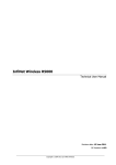
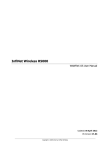
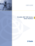
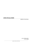
1
BreezeNET B300 Quick Installation Guide
WARNING:
The document is intended to be used by qualified RF engineers/technicians and IT professionals. Qualified
personnel should have skills and experience in the following areas: outdoor/indoor radio equipment
installation, outdoor wireless networks, TCP/IP networking protocols, safety procedures and instructions for
installing antenna equipment, professional manage of electrical equipment and accessories, safety
procedures and instructions for working on towers and heights.
WARNING:
The warranty is not spread for the devices which stopped working properly due to improper usage, careless
treatment, incorrect deployment or exploitation. The warranty voids in the following cases: the device was
opened and/or repaired by the owner on his own, improper exploitation conditions (including improper
grounding), electrical damaging of the print circuit board due to electric disruption caused by improper
grounding, mechanical defects of the case.
Installation Preparations
Components and accessories required for installation.
•
•
•
Indoor Unit (IDU)
Outdoor Unit (ODU)
Service cable for IDU-to-ODU connection. Service cable should be STP (or FTP) Category 5E cable. The total cable length
between LAN equipment (behind IDU) and ODU should not be longer than 100 meters.
•
One shielded and one unshielded RJ-45 connectors for service cable
•
Ethernet cable for connecting IDU to LAN equipment (use a straight for connection to a hub/switch or a cross-over cable for
connecting directly to a computer)
•
IDU’s AC power cord with a power plug
•
Console cable for having easy direct connection to ODU and performing initial configuration, link diagnostic, performance
monitoring
•
ODU mounting kit assembling. Pole, Low diameter pole or Wall mounting kits are available.
In case of using IDU with external antenna:
•
Antenna
•
Antenna installation kit assembling
•
RF low loss cable for connecting antenna to ODU
•
Required grounding system
Tools to be available at the installation site.
•
•
•
•
•
•
•
Screwdrivers set
Pliers
Spanners set
RJ-45 Crimp Tool (for RJ-45 connectors)
Connectors sealing set.
Optional: GPS receiver or area map with compass and alidade
Optional: Big zoom binocular
Cables preparation
1.
2.
3.
4.
In case of installing ODU with external antenna: prepare RF cable of the required length. RF low loss cable of 1 meter
length is recommended. Install and seal the connectors on the RF cable.
Determine the Service cable length that is used to connect IDU and ODU. The total cable length between LAN equipment
(behind IDU) and ODU should not be longer than 100 meters. Service cable should be STP/FTP Category 5E cable.
Install a connector for ODU on the Service cable and seal it (see Connector installation below).
If it is possible to lay the Service cable with a connector on the IDU side, install and seal connector for IDU on the Service
cable.
RJ-45 connector soldering scheme:
Connector installation
To install RJ-45 connector (without grounding) for ODU:
1. Peel the STP Service cable removing a small piece of its
external jacket to free the internal wires.
2. Put connector parts on the Service cable.
3. Attach RJ-45 connector to the Service cable according to
the “RJ-45” soldering scheme and crimp the connector.
4. Assemble the connector.
WARNING:
Connect UTP-cable with KEYED RJ-45
connectors ONLY to “ODU” port on the IDU. Do
NOT try to connect it to “LAN” port, it will
damage Keyed RJ-45 connector or IDU’s port.
-1P/N: 215269
April 2009
BreezeNET B300 Quick Installation Guide
Antenna, ODU, IDU installation.
Installation guidelines
1.
2.
3.
Install the antenna in the appropriate location (see antenna alignment instructions below). Antenna’s position must be lower
than the highest antenna pole point at least by 2 antenna heights. Point the antenna to the required direction. Provide
antenna grounding. (In case of using ODU with external antenna).
Connect RF cable to the antenna. Twist the connector tightly. Seal the connector. (In case of using ODU with external
antenna).
Install ODU having its connectors pointing down and tighten it. Appropriate place for ODU installation is as close as
possible to the antenna but reachable for you to connect ODU via its console port. Provide ODU grounding.
In case of using ODU with integrated antenna:
Install ODU according to the direction required for the link. Do not tighten it too hard unless the integrated antenna
alignment is not complete. Install ODU connectors down. Provide ODU grounding.
It is extremely important to install ODU connectors down!
4.
5.
6.
7.
8.
9.
Connect RF cable to the ODU previously having touched RF cable connector case with ODU connector case for removing
static electricity on the ODU. Seal the connector (in case of using ODU with external antenna).
Connect the STP/FTP Service (ODU-to-IDU) cable to the ODU. Seal the ODU connector.
Lay the STP/FTP Service cable “from top to bottom” – from ODU to IDU. Provide cable whipping before entering the
building. Whipping radius should be at least 10 times STP/FTP cable diameter.
If Service cable connector for IDU hasn’t been installed, install it. Seal the connector.
Install IDU. Provide IDU grounding.
Connect Service cable to IDU previously having touched IDU connector case with Service cable connector case for
removing static electricity on the IDU.
WARNING:
10.
11.
12.
13.
Connect UTP-cable with KEYED RJ-45 connectors ONLY to “ODU” port on the IDU. Do NOT try to connect it
to “LAN” port, it will damage Keyed RJ-45 connector or IDU’s port.
Connect Ethernet cable to IDU.
Connect power cord to IDU. Provide power supply.
Connect to the unit using Telnet protocol.
Configure basic configuration parameters (see Basic configuration instructions below).
Basic configuration
1.
2.
3.
4.
Connect to the ODU via ODU console port using console cable or via IDU LAN Ethernet port using wired LAN (start Telnet
protocol).
Configure your computer parameters. If you are using console port start any terminal emulation software (e.g. Hyper
Terminal), set console interface properties to 38400 baud rate, 8 bit, 1 stop bit, parity off, flow control disabled, enable
emulation mode ANSI or VT100, keyboard VT100. If you are using Telnet protocol from the wired LAN run Telnet with
10.10.10.1 IP-address that is configured for the Ethernet interface of the device by default.
You will see the WANFleX OS prompt. Enter login and password. Every new device login “admin” and password “private”.
After default authorization there will be standard prompt string.
Perform basic radio interface configuration using “rfconfig rf5.0” command. Basic parameters: radio frequency (‘freq’
parameter) in MHz, bit-rate (‘bitr’ parameter) in kBits/sec, system identifier (‘SID’ parameter). ‘SID’ – is a system identifier
of the unit (all units that are supposed to see each other on the same radio link must have the same identifier). For
example: rfconfig rf5.0 freq 5260 bitr 130000 sid 01010101. To learn your device’s radio module capabilities type the
command: rfconfig rf5.0 capabilities.
IMPORTANT:
Choose the frequency attentively. The frequency should be the one your radio link is working on.
Antenna alignment
Install antennas as high as possible over specific level. Proximity of other antennas should be avoided (at least 2 meters).
Consider reflecting surfaces (building with reflective windows, water surfaces or wet grounds). When installing antenna over
water surface, one should tune height bracket within 1-3 meter range variation, because it can yield signal level variation from
minimum to maximum.
To obtain the best performance results, it is necessary to perform a precise analysis of a LOS conditions, signal propagation
path zone and possible obstructions that may cover a part of the 1st Fresnel zone. Possible obstructions on the signal
propagation path are neighboring buildings, trees, bridges, power lines.
Antenna polarization must be taken into consideration while installation. In most cases Omni-directional and sector antennas
have a vertical polarization. Directional antennas can be installed either with vertical or horizontal polarization. Please check a
corresponding labeling on the antenna and address to the antenna technical documentation.
-2P/N: 215269
April 2009
BreezeNET B300 Quick Installation Guide
Recommendations for antenna alignment: align antennas using optical equipment (binoculars, spyglass) accompanied by
mobile phone actions coordination, use GPS receiver and area map. These features allow evaluating current channel/signal
quality and perform precise antenna alignment. To achieve the best link quality on the radio link use “Spectrum Analyzer” and
“Ltest” utilities. See complete description of these utilities in “OS WANFleX Manual” and “Technical User Manual”.
Grounding
Antenna should be placed on the mast on the level that is at least 1 meter lower than a mast’s top. In this case it is of big
probability that the lightning strikes the mast and not the antenna. The mast is to be grounded on the grounding contour
according to your local standards.
A special attention should be paid if antenna used is not DC-shorted. In this case additional lightning arrestor should be used
between the antenna and ODU. Suggested grounding diagram is shown on the picture below.
Antenna pole, tower, ODU and lightning arrestor should be connected to the first common grounding contour. Cable thickness
should be no less than 10AWG using corrosion-steady connectors. It is highly recommended to entrust grounding contour
development to the skilled personnel. IDU should be grounded to the same contour as customer LAN, having the second
common grounding contour.
Connector hermetic sealing
A big number of problems with link signal quality in case of outdoor installations result from RF cable and connectors corrosion.
In order to avoid these problems it is necessary to isolate all the connections that are situated outdoors. It is recommended to
use either thermal shrinkage with gel stuff or special waterproof tape.
Once the antenna alignment is not complete it is not recommended to perform sealing. This prevents you to remove the sealing
when there is a need to reallocate the antenna or the cable. The isolation using the waterproof tape is performed by its winding
with intersection around the connection.
Please keep in mind the following recommendations: clean all the surfaces to be isolated and keep them free from the dust and
water, sealing material must cover the whole connector and the cable with a gap of at least 2-3 cm from the connection place,
sealing material must cover the surfaces as tight as possible.
To protect the sealing material from the sun rays, it is recommended to cover it with vinyl isolation tape.
-3P/N: 215269
April 2009