1
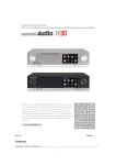
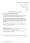
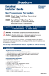
Operation and Installation Guide HDS2800 Series Encoder Modulator High Definition (HD) Digital COFDM MPEG2 and H.264 Modulator with IP Multicast. 19” Rack Mount Revision 4.0 Firmware version Released File HDS2800 Rev 4.0.Docx HDS2800 Operation and Installation Contents 1.0 Key Features: .................................................................................................................................... 3 2.0 HDS2800 Rack and Wall Frames ..................................................................................................... 4 2.1 Indicators and Key-buttons Details ................................................................................................ 4 2.2 Installation: .................................................................................................................................... 5 3.0 Operation from the front panel .......................................................................................................... 6 4.0 Programming via inbuilt Web Server / NMS operation ..................................................................... 7 4.1 Connection and Login.................................................................................................................... 7 4.2 Input configuration setting ............................................................................................................. 8 4.2.1 Select the Input(n) setting. ...................................................................................................... 8 4.2.2 ASI Input Setting ................................................................................................................... 10 4.3 NIT table setting .......................................................................................................................... 12 4.3.1 Add, Set, Edit the NIT table .................................................................................................. 13 4.4 IP Output Setting ......................................................................................................................... 14 4.5 Modulator setting ......................................................................................................................... 15 4.6 Utilities - Save/Restore ................................................................................................................ 16 4.7 Reboot ......................................................................................................................................... 18 4.8 Firmware ...................................................................................................................................... 18 TeleDelta is proudly an Australian owned company. File: hds2800 rev 4 www.teledelta.com Page 2 of 18 HDS2800 Operation and Installation 1.0 Key Features: • • • • • Transparent resolution pass through up to 1920x1080 and 1280x720 @ 50P/60P (1080P, 1080I and 720P resolution – depending on input modules) 1 or 2 input modules provide up to 4 inputs (format and rate dependant) Input formats: - HDMI - HD/SD-SDI, - Composite PAL (CVBS 576I resolution) - ASI Multiple outputs: - on coax as selectable COFDM DVB-T (MPEG 2 and H.264) - as IP; MPTS UDP Multicast - as ASI Modular design – select input modules to suit the application. • The HDS2800 series supports HDCP, Channel naming, installer selectable LCN’s and DVB tables. • Front panel LCD or built-in webserver . • Frame chassis options include wall mount • (1HD or 2 SD inputs), and rack mount options (2+ HD and 4+ Comp input channels) • High quality modulation MER > 42. • Output bandwidth fully adjustable up to 27Mbps • Individual channel rate adjustment • Selectable: - RF Frequency - RF Power output, - FEC, - Guard Intervals - Constellation • HDMI modules auto switching provides redundant inputs • Multiple HD/SD channels can be daisy-chained together to output as a single digital RF channel or can be spread over multiple RF channels. • The HDS2800 has an excellent cost per HD digital channel. TeleDelta is an Australian owned company, with local engineering and support facilities in Australia and New Zealand for more information please visit our website www.teldelta.com TeleDelta is proudly an Australian owned company. File: hds2800 rev 4 www.teledelta.com Page 3 of 18 HDS2800 Operation and Installation 2.0 HDS2800 Rack and Wall Frames 2.1 Indicators and Key-buttons Details Rack Mount Frame 1 2 3 9 4 5 7 6 8 10 1 Wall Mount Frame 3 10 5 4 9 2 w i t h 6 t h e 8 7 I S O / I E C 1 3 8 1 LCD display 1 2 NMS port - access to internal 8 management web server 3 Power Indicator 1 4 Channel Lock light(s) 5 Up and down, left and right button [ 6 Enter button: for confirm 1 7 Menu button: for back step ] 8 Lock button: press to lock / unlock s 9 Data port – IP multicast output p 10 Alarm indicator e c i f i c a TeleDelta is proudly an Australian owned company. t www.teledelta.com i o n , b File: hds2800 rev 4 Page 4 of 18 HDS2800 Operation and Installation 2.2 Installation: This section outlines some of the precautions users must maintain when installing, servicing and operating the TeleDelta HDS2800 Series. General Precautions Operate the HDS2800 in a dry, dust free environment Unless qualified, do not open the cover of the HDS2800, doing so may void all warranty purposes. Exercise caution when operating any electrical device, do not operate any device unless you are qualified to do so. Do not stick your fingers into a light bulb socket. TeleDelta is proudly an Australian owned company. File: hds2800 rev 4 www.teledelta.com Page 5 of 18 HDS2800 Operation and Installation 3.0 Operation from the front panel This version of the manual is intended for setup and maintenance of the unit using the NMS web interface. For front panel (LCD) operation please refer to the LCD supplement – available on request TeleDelta is proudly an Australian owned company. File: hds2800 rev 4 www.teledelta.com Page 6 of 18 HDS2800 Operation and Installation 4.0 Programming via inbuilt Web Server / NMS operation The inbuilt web interface allows fast setting of the unit’s parameters. The web interface is required for the setting of the LCN and NIT table as well as labelling the input for on-screen display, OSD. 4.1 Connection and Login 1 Connect a PC equipped with a modern browser to the NMS port. The HDS can be connected with a straight through cable or via a hub / switch. Point your browser at the IP address for the unit. The IP that is set for the unit can be read at LCD menu location 5.1. Hint: To read the IP address from the LCD, press Lock key to enter the menu tree and navigate to menu 5.1 A login interface will appear. Both of the default user name and password are admin and are case sensitive. Hint: To reset the username and password to default from the LCD, press Lock key to enter the menu tree and navigate to menu 5.5 After login, the Welcome system status screen will display 1 As at May 2102 Google Chrome 18.0.1025.168 m, and IE9.0.6 are known to work. Goodness knows what the future will hold… TeleDelta is proudly an Australian owned company. File: hds2800 rev 4 www.teledelta.com Page 7 of 18 HDS2800 Operation and Installation 4.2 Input configuration setting 4.2.1 Select the Input(n) setting. A HDMI input card is shown below Label Options Comment Video format User set MPEG2 / H.264 selectable video format on certain HD (HDMI) frames Video bit rate User set The range is 1~19.5Mbps* Audio format / bit rate:, Default The default value is MPEG2 and 128kbps and is not normally changed Program out enabled User set Turn on/off program output Program name User set Enter the program name to be displayed on the TV PMT/Video/Audio/PCR PID. Default System will automatically select the default values Encoding and video indicators Indication only Green is normal, Red is fault HDMI input: it Indication only Indicates if there is real-time HDMI signal present Video format: Indication only the current video format of the device Bit rate: Indication only the current encoding bit rate Interface settings must be altered to reflect the input modules on the HDS-2800. For RCA modules the interface defaults to VGA, this must be changed to RCA. The aspect ratio for RCA input modules must also be changed to 16:9. Repeat the setup as required for all inputs fitted (1-4). TeleDelta is proudly an Australian owned company. File: hds2800 rev 4 www.teledelta.com Page 8 of 18 HDS2800 Operation and Installation TeleDelta is proudly an Australian owned company. File: hds2800 rev 4 www.teledelta.com Page 9 of 18 HDS2800 Operation and Installation 4.2.2 ASI Input Setting ASI Input If fitted the ASI option is fitted the ASI tab will display ASI input program information as below. In this example an incoming ASI stream carries Seven Networks DTT formats as a 20+MiB stream. Filtering is carried out to output only 7Digital and PID 18 Label Options Output A - B User set Passthrough User set Multiplex User set Enable mux to select which programs are passed through Refresh Input Click Click to re scan the input stream and rebuild program list Refresh Output Click Click to refresh the Output program list Select Program Click Transfers input programs marked with “√”, to the output stream Cancel Program Click Removes output programs marked with “√”, from the output stream All Input Click Selects all the input programs with one-click. All Output Click Selects all the output programs with one-click. Parse Timeout Default Time limitation to parse the input stream (before TimeOut) PID Pass Default Table is blank – see details below TeleDelta is proudly an Australian owned company. Comment Select the carrier output channel for the multiplexed programs. This selection does not exist for the HDS2800 single carrier units.) If selected, all the input programs will pass through without any changes. File: hds2800 rev 4 www.teledelta.com Page 10 of 18 HDS2800 Operation and Installation Click the PID Pass button to trigger a dialog box as below, enter any PIDs required for pass through. In some streams, there are required PIDs which won’t belong to any program, (such as EPG & NIT tables,) from here you can pass them through the multiplexing module without changing anything. Click “Add” to add more boxes for the Input & Output PIDs, then click “Apply” to confirm. TeleDelta is proudly an Australian owned company. File: hds2800 rev 4 www.teledelta.com Page 11 of 18 HDS2800 Operation and Installation 4.3 NIT table setting The location of the NIT is defined in compliance with the ISO/IEC 13818-1 [1] specification, but the data format is outside the scope of ISO/IEC 13818-1 [1]. It is intended to provide information about the physical network. Important: Set the Modulator settings BEFORE creating a NIT. (refer Modulator section 4.5 below) An existing table entry The syntax and semantics of the NIT are defined as follows, (Defaults are shown above) • Network name: The name of current network, user can set as required. • Network ID: This is a 16-bit field which identifies the terrestrial network that supports the service indicated. The NIT table MUST be updated for both modules, A and B. If there are no existing table entry’s, add a new table with the following RF Frequency; 550.500MHz. Leave all other parameters as default and set the LCN’s in ascending numbers. (E.g. 101, 102, 201, 202...) Refer to the next section for Adding, setting editing the NIT table. • • Update NIT: click to update the NIT tables in system, always do this after an update to the table Clear NIT: click to remove all the tables that have been inserted before. TeleDelta is proudly an Australian owned company. File: hds2800 rev 4 www.teledelta.com Page 12 of 18 HDS2800 Operation and Installation 4.3.1 Add, Set, Edit the NIT table Click “Del-All” and “Add” to pop up a new table, or “Detail” to show the existing table. Label Options Comment Transport stream ID Inherited 16-bit field label identifying the TS which contains the service, event or mosaic described by the cell. The default value is not normally changed. Inherited from previous window Original network ID Inherited 16-bit field, a label which in conjunction with the following fields uniquely identifies a service, event or mosaic. The default value is not normally changed. Inherited from previous window RF Frequency Inherited Inherited from Modulator settings. Don’t change. Bandwidth Inherited Inherited from Modulator settings. Don’t change. Constellation Inherited Inherited from Modulator settings. Don’t change Hierarchy information Not used Hierarchy information: this option only for ISDB-T standard device. Don’t change Code rate Inherited Inherited from Modulator settings. Don’t change Guard interval Inherited Inherited from Modulator settings. Don’t change Transmission mode Inherited Inherited from Modulator settings. Don’t change Service ID Inherited Inherited from Input settings. Don’t change LCN: logical channel number User set Enter the logical channel number. The LCN can be added more than one by re-clicking “Add” option TeleDelta is proudly an Australian owned company. File: hds2800 rev 4 www.teledelta.com Page 13 of 18 HDS2800 Operation and Installation • • • Del: clicking “Del” to delete the added LCN information Save: clicking “Save” to save the current NIT parameters Cancel: clicking “Cancel” to exit the edit interface 4.4 IP Output Setting Follow the on screen help guidelines for setting the IP output configuration. Separate documentation is available for the implementation of IP systems. Note: In this example if using VLC, set the VLC network stream to udp://@224.2.2.2:1234 and connect the stream from the DATA port – ensure your computers firewall is either disabled or accepting of the above port address TeleDelta is proudly an Australian owned company. File: hds2800 rev 4 www.teledelta.com Page 14 of 18 HDS2800 Operation and Installation 4.5 Modulator setting Label Options Comment Bandwidth User set the range is: 6MHz, 7MHz and 8MHz. Australia is 7MHz Constellation User set QPSK, 16QAM and 64QAM. Use 64QAM Transmission mode User set Use 8K Guard interval User set Use 1/8 Code Rate User set Use 2/3 RF Frequency User set Range is 30~1000MHz RF output level User set Range is -30~-10dBm Set RF Frequency to 550.500MHz for Australian compatibility. TeleDelta is proudly an Australian owned company. File: hds2800 rev 4 www.teledelta.com Page 15 of 18 HDS2800 Operation and Installation 4.6 Utilities - Save/Restore Follow the on screen help guidelines Labels Comment Save Boot Configuration Saves the current setup as the start-up or restore settings. Restore Boot Configuration Cancels current settings and restores the last saved settings Factory Default Configuration Resets all settings to factory defaults. Backup Configuration Saves the current setup to a re-loadable file *Continued Below: TeleDelta is proudly an Australian owned company. File: hds2800 rev 4 www.teledelta.com Page 16 of 18 HDS2800 Operation and Installation Labels Comment Load Configuration Load a saved configuration from file Firmware Update Update of existing firmware User Access Adjustment of login, password and security details Backup Configuration Saves the current setup to a re-loadable file TeleDelta is proudly an Australian owned company. File: hds2800 rev 4 www.teledelta.com Page 17 of 18 HDS2800 Operation and Installation 4.7 Reboot Click to initiate a re-boot of the unit and the re-load of the most recently saved settings (see above) 4.8 Firmware This function is used to upgrade the device’s latest software program. Follow the instructions provided with the software updates. TeleDelta is proudly an Australian owned company. File: hds2800 rev 4 www.teledelta.com Page 18 of 18