1
B410/B420/B430/MPS420b
Maintenance Manual
080409B
Oki Data CONFIDENTIAL
Copyright © 2008 by Oki Data. All Rights Reserved
Oki Data America's, Inc. ("Oki Data"), authorizes you to view, copy, and print
documents published by Oki Data for noncommercial use within your organization only.
In consideration of this authorization, you agree and acknowledge that any copy of these
documents shall retain all copyright and proprietary rights contained herein. Each
document published by Oki Data may contain additional copyright information and
proprietary notification relating to that individual document.
Nothing contained herein shall be construed as conferring by estoppel, implication or
otherwise any license or right under any patent or trademark of Oki Data, Oki Electric
Industry Co., Ltd. ("Oki Electric"), or any third party. Except as provided above nothing
contained herein shall be construed as conferring any license or right under any Oki
Data copyright.
Oki Data has taken care to insure that the information which follows is complete,
accurate and up-to-date. However, Oki Data assumes no responsibility for errors or
omissions which may occur. All the information provided is subject to change from time
to time at the sole discretion of Oki Data.
All publications may include technical inaccuracies or typographical errors. We reserve
the right to make periodic changes, additions, and deletions to publications without
notice.
The most up-to-date drivers and manuals are available from the web site:
http://www.okiprintingsolutions.com
Oki Data CONFIDENTIAL
PREFACE
Oki Data CONFIDENTIAL
PREFACE
This Maintenance Manual describes the maintenance methods in the printer field for the maintenance
personnel. In addition, regarding the handling and operating method of the printer, please refer to the "User’
s Manual".
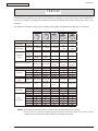
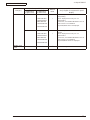
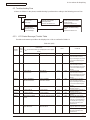
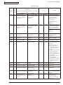
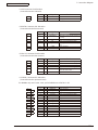
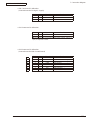
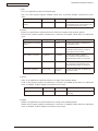
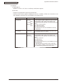
The differences between various types of printers described in this Maintenance Manual are as follows.
B410d
B410dn
B420dn
Engine speed (letter/A4)
Max.
Resolution
resolution
30/28
2400 x 600
dpi
30/28
2400 x 600
dpi
30/28
2400 x 600
dpi
Standard
PCL6/SIDM
Emulation
Operation
panel
Option
LCD
display
N/A
16 character x
2
1 (online/
Switch
offline)
2
LED lights
Input tray (Manual/Auto)
Single sheet
manual feed
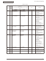
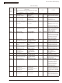
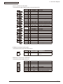
B430d
B430dn
30/28
30/28
1200 x 1200 1200 x 1200
dpi
dpi
dp
PCL6/PS3/
PCL6/PS3/
PCL6/PS3/
PCL6/SIDM PCL6/SIDM
SIDM
SIDM
SIDM
N/A
N/A
N/A
N/A
N/A
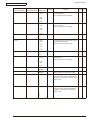
16 character x 16 character x 16 character x 16 character x 16 character x
2
2
2
2
2
1 (online/
6
6
6
6
offline)
2
2
2
2
2
50 sheets
50 sheets
50 sheets
50 sheets
Single sheet
Multi Purpose Multi Purpose Multi Purpose Multi Purpose
manual feed
Feeder
Feeder
Feeder
Feeder
250 sheets
530 sheets
250 sheets
250 sheets
530 sheets
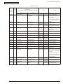
781
1110
830
830
1110
250 sheets
Input tray (1st bin)
781
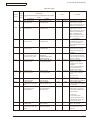
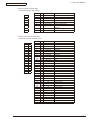
Maximum Input capacity
USB 2.0
Parallel
Interface
N/A
N/A
Ethernet
Standard
Standard
Standard
Standard
Standard
Standard
Auto Duplex
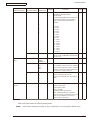
Monthly Duty
Maximum 50,000 pages 50,000 pages 70,000 pages 70,000 pages 70,000 pages 70,000 pages
Cycle
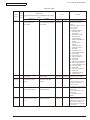
Toner life@ISO19752
Dimensions
(inch./mm)
Sales
Territories
Width
Depth
Height
ODA 100v
ODA 200v
OEL
AOS 1byte
AOS 2byte
Japan
China
3,500 (7,000
available for
JPN only)
14.5”/369mm 14.5”/369mm
15.6"/395mm 15.6"/395mm
10.6"/268mm 10.6"/268mm
3,500
3,500/7,000/
10,000
3,500/7,000
3,500/7,000
3,500/7,000/
10,000
14.5”/369mm 14.5”/369mm 14.5”/369mm
15.6"/395mm 15.6"/395mm 15.6"/395mm
11.7"/297mm 10.6"/268mm 10.6"/268mm
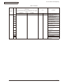
N/
N/A
N/A
N/A
N/A
N/A
TBD
TBD
N/A
N/A
TBD
TBD
TBD
Note! • It is prohibited to reprint entire or partial of the content without prior consent.
• For the reason of printer improving and manual content revising, the content of this
maintenance manual may change without any warning in the future.
43984801TH Rev.1
/
Contents
Oki Data CONFIDENTIAL
Contents
1. CONFIGURATION......................................................................................................... 7
1.1 System Configuration .............................................................................................................................7
1.2 Printer Configuration...............................................................................................................................8
1.3 Optional Configuration...........................................................................................................................11
1.4 Specification..........................................................................................................................................12
1.5 Printing display......................................................................................................................................15
1.5.1 VCCI label, Serial No. label.............................................................................................................15
1.5.2 Warning label...................................................................................................................................15
1.5.3 Warning / Caution display................................................................................................................16
2. Operational explanation.............................................................................................. 17
2.1 Electrophotographic process mechanism ............................................................................................17
2.2 Printing process.....................................................................................................................................24
2.3 Toner entrance detection.......................................................................................................................28
3. Parts replacement....................................................................................................... 30
3.1 Preparation for parts replacement.........................................................................................................30
3.2 Parts layout............................................................................................................................................32
3.3 Parts replacement method....................................................................................................................37
3.3.1 LED Head........................................................................................................................................38
3.3.2 Roller-Transfer.................................................................................................................................39
3.3.3 Cover-Side-R...................................................................................................................................40
3.3.4 Cover-Side-L...................................................................................................................................41
3.3.5 CU Board.........................................................................................................................................42
3.3.6 Motor-DC-Main . .............................................................................................................................43
3.3.7 OPE Cover-Assy.............................................................................................................................44
3.3.8 Ope-Board.......................................................................................................................................45
3.3.9 MPT-Assy (In case of B410dn, it is Manual-Assy)...........................................................................46
3.3.10 Front-Guide-Assy..........................................................................................................................47
3.3.11 Roller-Assy-Feed...........................................................................................................................48
3.3.12 Guide-Paper-Duplex......................................................................................................................49
3.3.13 Stacker-Cover-Assy.......................................................................................................................50
3.3.14 Fuser-Assy....................................................................................................................................51
3.3.15 Rear-Cover-Assy...........................................................................................................................53
3.3.16 Frame-Assy-Lower........................................................................................................................54
3.3.17 High voltage / Low voltage power board........................................................................................56
3.3.18 Plate-Bracket-Motor.......................................................................................................................57
3.3.19 Roller-Back up...............................................................................................................................58
3.3.20 Roller-Resist..................................................................................................................................59
3.3.21 Lever-In-Sensor.............................................................................................................................60
3.2.22 Lever-Eject-Sensor/Photo-Interrupter............................................................................................61
3.3.23 Lever-End/Lever-Duplex/Lever-Cassette/Gear-Assy-Clatch.........................................................62
3.3.24 Paper feeding roller (Roller-Pick-Up,Roller-Feed-NOW,Roller-Assy-MPT)...................................64
43984801TH Rev.1
/
Oki Data CONFIDENTIAL
Contents
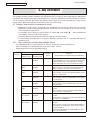
4. ADJUSTMENT............................................................................................................ 66
4.1 Category and function of maintenance mode........................................................................................66
4.4.1 User maintenance mode (Administrator Menu) . ............................................................................66
4.1.2 System maintenance mode (System maintenance menu)..............................................................71
4.1.3 Engine maintenance mode..............................................................................................................76
4.1.4 Environment mode setting...............................................................................................................84
4.1.5 EEPROM Initialization.....................................................................................................................85
4.2 Adjustment at part replacement............................................................................................................86
4.2.1 EEPROM data upload / download method......................................................................................86
5. Periodic Maintenance.................................................................................................. 87
5.1 Periodic Replacement Parts..................................................................................................................87
5.2 Cleaning................................................................................................................................................87
5.2.1 Cleaning of LED lens array..............................................................................................................87
5.2.2 Cleaning Page Function..................................................................................................................89
6. Procedures for Repairing............................................................................................ 90
6.1 Troubleshooting.....................................................................................................................................90
6.2 Points to be checked before modifying printing problems......................................................................90
6.3 Points to be checked when the printing problems are modified............................................................90
6.4 Preparation for Troubleshooting.............................................................................................................90
6.5 Troubleshooting Flow.............................................................................................................................91
6.5.1 LCD Status Message/ Trouble Table................................................................................................91
6.5.2 LCD Message Troubleshooting.....................................................................................................103
6.5.3 Print Troubleshooting.....................................................................................................................111
7. Connection Diagram.................................................................................................. 119
7.1 Connection diagram............................................................................................................................119
7.2 Board Layout.......................................................................................................................................120
7.3 Resistance value.................................................................................................................................134
Appendix A Centronics Parallel Interface...................................................................... 136
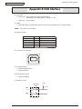
Appendix B USB Interface............................................................................................ 143
Appendix C Maintenance Manual for Second Tray unit................................................. 145
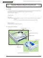
1 Overview................................................................................................................................................145
1.1 Function............................................................................................................................................145
1.2 Exterior and Parts Name..................................................................................................................145
2. Description for Operation of Second Tray unit.......................................................................................146
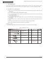
3. Part Replacement..................................................................................................................................147
3.1 Precautions on replacing parts.........................................................................................................147
3.2 Arrangement of Parts.......................................................................................................................148
3.3 How to Replace Parts.......................................................................................................................149
3.3.1 Roller-Pick-Up, Roller-Feed-Now..............................................................................................150
3.3.2 Guard-Connector. Connector (9715S-08Z02-G4C)...................................................................151
3.3.3 Roller-Feed................................................................................................................................152
3.3.4 Board-OT7.................................................................................................................................153
43984801TH Rev.1
/
Oki Data CONFIDENTIAL
Contents
3.3.5 CONN Cord-AMP8P-AMP8P....................................................................................................154
3.3.6 Gear-Assy-Clatch......................................................................................................................155
3.3.7 Frame-Assy-Retard, Spring-Retard...........................................................................................157
4. Cleaning of Paper Feed Roller and Separation Roller...........................................................................158
5. Procedure for Troubleshooting...............................................................................................................159
5.1 Precautions for Troubleshooting.......................................................................................................159
5.2 Preparation before Troubleshooting..................................................................................................159
5.3 Troubleshooting Method...................................................................................................................160
5.3.1 LCD Status Message List..........................................................................................................161
6. Connection Diagram..............................................................................................................................163
6.1 Connection diagram.........................................................................................................................163
6.2 Board Arrangement..........................................................................................................................163
Appendix D Network Interface...................................................................................... 165
43984801TH Rev.1
/
43984801TH Rev.1
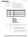
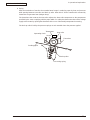
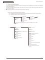
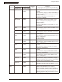
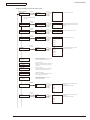
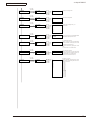
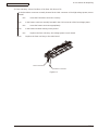
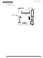
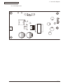
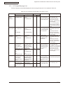
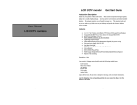
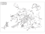
Operator panel board
FAN
WRT
sensor
Transfer roller
Toner inlet
sensor
Stacker cover open SW
IN
sensor
High voltage power supply uint
Tag transit board 1
Tag transit board 2
Image drum cartridge
Tag transit board 3
Tag board
Toner cartridge
LED head
LCD:1, LED:2, SW:1(B410d/B410dn)
LCD:1, LED:2, SW:6
(B420dn/B430d/B430dn)
CENTRONICS
AC inlet
AC-SW
Low voltage
power supply unit
LAN
(10BASE-T/100BASE-TX)
Main print circuit board
USB 2.0
FUSE
Temperature sensor
Halogen lamp
Fuser unit
Rear cover open sensor
Exit sensor
Paper end sensor
Cassette & Duplex detecting
Solenoid for paper inverting
Hopping clutch (MPT)
Register clutch
Hopping clutch (1st)
Main DC Motor
2nd tray unit*
Oki Data CONFIDENTIAL
1. CONFIGURATION
1. CONFIGURATION
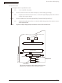
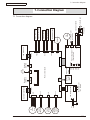
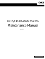
1.1 System Configuration
As the diagram 1.1 shows, for the standard configuration printer is configured by controller unit and
engine unit.
Figure1-1
/
1. CONFIGURATION
Oki Data CONFIDENTIAL
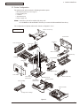
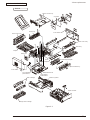
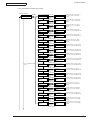
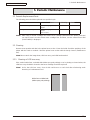
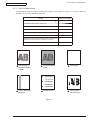
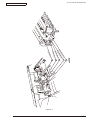
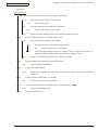
1.2 Printer Configuration
The printer main unit includes the following hardware parts.
•
•
•
•
•
Electrophotographic processing part
Paper feeding part
Controller
Operational part
Power supply unit
Note! • Fuser-Assy has to be replaced by Assy unit.
• It is forbidden to disassemble Fuser-Assy or reuse the disassembled Fuser-Assy.
The configuration of printer main unit is shown as diagram 1-2~1-4
Stacker-Cover-Assy
B410d/B410dn
Cover-Side-R
CU board
Rear-Cover-Assy
Fuser-Assy
A
OPE Cover-Assy
A’
A
Manual-Assy
Duplex
Guide-Paper-R
Motor-Fan
Guide-Paper-Duplex
Cover-Side-L
A’
Low voltage
power board
Toner cartridge
Plate-Base-PCB
High voltage
power board
Front-Guide-Assy
Plate-Assy-Base
Paper cassette
Image drum cartridge
Figure1-2
43984801TH Rev.1
/
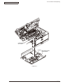
1. CONFIGURATION
Oki Data CONFIDENTIAL
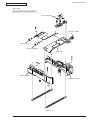
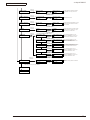
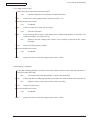
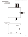
B430d/B430dn
Stacker-Cover-Assy
Cover-Side-R
CU board
Rear-Cover-Assy
Fuser-Assy
A
OPE Cover-Assy
A’
A
MPT-Assy
Duplex
Guide-Paper-R
Motor-Fan
Guide-Paper-Duplex
Cover-Side-L
A’
Low voltage
power board
Plate-Base-PCB
Front-Guide-Assy
Plate-Assy-Base
Toner cartridge
High voltage
power board
Paper cassette
Image drum cartridge
Figure1-3
43984801TH Rev.1
/
1. CONFIGURATION
Oki Data CONFIDENTIAL
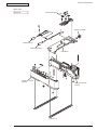
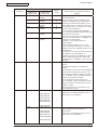
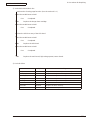
B420dn
Stacker-Cover-Assy
Cover-Side-R
CU board
Rear-Cover-Assy
Fuser-Assy
A
OPE Cover-Assy
A’
A
MPT-Assy
Duplex
Guide-Paper-R
Motor-Fan
Guide-Paper-Duplex
Cover-Side-L
A’
Low voltage
power board
Toner cartridge
Plate-Base-PCB
High voltage
power board
Front-Guide-Assy
Plate-Assy-Base
Paper cassette
Image drum cartridge
Figure1-4
43984801TH Rev.1
10 /
Oki Data CONFIDENTIAL
1. CONFIGURATION
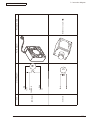
1.3 Optional Configuration
The options attached to the printer are as follows. These options can be ordered respectively for the
printer main unit.
(1) Second tray unit
(2) Additionally installed memory (Domestic oriented printer only use 128MB.)
43984801TH Rev.1
11 /
1. CONFIGURATION
Oki Data CONFIDENTIAL
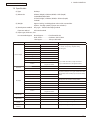
1.4 Specification
(1) Type
Desktop
(2) Dimension
268mm (Height) x 369mm (Width) x 395 (Depth)
:B410d/B410dn/B430dn
297mm (Height) x 369mm (Width) x 395mm (Depth)
:B420dn
(3) Weight
Approx. 10.6kg ( Including printer main unit & consumables.
Options, Feeding quantity of paper are excluded.)
(4) Development method
Dray type – Element developing method
Exposure method
LED Head method
(5) Paper type, thickness, Size
Recommended paper
Normal paper………….Excellent white A4
OHP Sheet…………….Sumitomo 3M CG3300
Label paper…………….Kokuyo LBP-A693
Category
Size unit: mm (inch)
Thickness
A4
Weight 55~105kg(64~120g/m2)
A5
For double-side printing, weight55~90kg
A6
(64~105g/m2)
B5
Letter
Normal Paper
Legal
Legal
Statement
Executive
Custom
Postcard
Tray 1, Width 100~215.9, Length 210~355.6
Width86~215.9
Tray 2, Width 148~215.9, Length 210~355.6
Length 140~355.6
Postcard
Postcard
Return Postcard
Envelope 1 (Chou #3)
The envelope should be using 85g/m paper. The
flap of the envelope Chou type should not be with
fold, the flap of the envelope you should be clearly
folded.
Envelope 2 (Chou #4)
Envelope 3 (You #4)
The envelope should be using 24 lb. paper and
the flap part of it should be clearly folded.
Envelope
Custom
Label Paper
OHP Sheet
Width86~215.9
Length 140~355.6
Letter
Letter
Partial Printing
Paper
Weight 55~105kg(64~120g/m2)
Paper for Color
Printing
Weight 55~105kg(64~120g/m2)
43984801TH Rev.1
12 /
1. CONFIGURATION
Oki Data CONFIDENTIAL
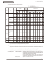
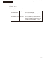
(6) Paper feeding method / Ejecting method
○ : It is possible to use it.
× : It is not possible to use it.
△ : It is possible to use it by a part of size
Paper
feeding Method
Type
Normal
paper
Postcard
*5
Envelope
*5
Size
Thickness
(Weight:Kg)
A5 *5
B5 *5
Executive *5
Weight
55~105kg
Statement *5
Weight
55~105kg
A4
Letter
Legal (13 inch)
Lega (14 inch)
Custom *3 *5
Width 86~215.9mm
Length
140~355.6mm
Weight
55~90kg
Weight
91~105kg
Postcard
or less
than
weight
135kg
Envelope1 (CHOU
3)
Envelope2 (CHOU
4)
Envelope3 (YOU 4)
Com-9
Com-10
DL
C5
C6
Monarch
*6
Custom
Width 86~215.9mm
Length
140~355.6mm
*6
Label
paper
A4/Letter
0.1~
0.5mm
OHP
A4/Letter
0.1~
0.5mm
*6:
Automatic
Manual
double-side print *2
double-side print
Multipurpose
Face Face
Manual
tray *1
up down
Tray 2 Multipurpose
Tray 2 Multipurpose
Tray 2
Tray 1
Manual Tray 1
Manual
Tray 1
4
*
tray*1
*4
tray *1
*4
Paper
cassette
Weight
91~105kg
Weight
55~105kg
*1:
*2:
*3:
*4:
*5:
Double-side print
Weight
55~90kg
A6 *5
Postcard/
Return postcard
Paper
ejecting
method
Multipurpose tray can be used for B420dn/B430dn.
Face-up paper ejecting is not available at automatic double-side printing.
Tray 1 is as width 100~21539mm, length 210~355.6mm. Tray 2 is as width 148~215.99mm, length 210~355.6mm.
Tray 2 (The second tray unit) is for option.
In case to set up the paper size for A5, A6, Postcard, Envelope, if the width of B5, Executive, Statement, Normal paper is less
than 200mm, also if thick paper or thicker paper has been set up for the paper thickness, the printing speed changes to be
slowly. • Envelope CHOU should be made by the paper or basis weight of 85g/m2 and without any fold on the flap part.
• Envelope YOU should be made by the paper of basis weight of 85g/m2 and with clear fold on the flap part.
• Com-9, Com-10, Monarch, C5, C6, and DL should be the envelope using 24lb paper and with clear fold on the flap part.
(7) Printing speed
Continuous printing : Maximum 28 piece/second (A4, At copy mode, First try)
For Envelope • Postcard, if to enhance the printing quality, the
printing speed changes to be decreased.
For the resolution degree of 600 x 2400, if to enhance the
printing quality, the printing speed changes to be decreased.
Warm up time
43984801TH Rev.1
: Approx. 25 second (25°C, 100V)
13 /
1. CONFIGURATION
Oki Data CONFIDENTIAL
(8)
Paper feeding method
Automatic feeding
(9)
Paper ejecting method
Face down (Rear ejecting) / Face up (Front ejecting)
(10)
Resolution (Max.)
2400 × 600 dots / inch (B410d/B410dn/B420dn)
1200 × 1200 dots / inch (B430d/B430dn)
(11)
Input electricity
AC100V ± 10V, 50/60Hz ± 1Hz(B410dn/B430dn)
(12)
Electricity consumption
Up and running: Maximum 800W, Average 450W (25°C)
Ready and waiting: Average 70W (25°C)
Power-saving mode: (Without option) Under 6W
(With option)
Maximum 7W
(13) Temperature and Humidity
Tenperature
Up and
running
Humidity
10~32
20~80%RH (Relative Humidity) No condensation.
However, Maximum temperature of wet ball should
be 25°C.
Power switch 0~43
off
Keeping
10~90%RH (Relative Temperature) No
condensation. However, Maximum temperature of
wet ball should be 26.8°C.
-10~43
10~90%RH (Relative Humidity) No condensation.
However, Maximum temperature of wet ball should
be 26.8°C.
Temperature (°C)
32
28
Up and running
10
20
80
Relative humidity (%)
(14) Operating noise
In Printing
: Rage A based on JIS Z9831, Average below 53dBA for SLOW.
Ready and waiting : Rage A based on JIS Z9831, Average below 53dBA for SLOW.
At power save
: No sound (Background level)
(15) Consumables
Toner cartridge
: Approx. 3,500 piece /Approx. 7,000 piece/Approx. 10,000
piece(A4 ISO/IEC 19752 Continuous printing as
printing paten. But, except the 1st Toner cartridge)
Image drum
: Approx. 25,000 piece (Continuously single-side printing of A4)
Cartridge
: Approx. 20,000 piece (Single-side 3 pages/job) At Power save off.
Approx. 12,000 piece (Single-side 1 page/job) At Power save off.
Approx. 7,000 piece (Single-side 1 page/job) At Power save on
(Minimum value).
43984801TH Rev.1
14 /
Oki Data CONFIDENTIAL
1. CONFIGURATION
1.5 Printing display
1.5.1 VCCI label, Serial No. label
The VCCI label and Serial No. label have been attached on the specified part of printer as shows
below.
B410dn
B430dn
Serial No.
Made In China
1.5.2 Warning label
Warning label has been attached on the part of printer that may cause injury to the operator.
Maintenance must be performed following the indication of the warning label.
43984801TH Rev.1
15 /
1. CONFIGURATION
Oki Data CONFIDENTIAL
1.5.3 Warning / Caution display
The following warning / caution are displayed on the electrical power / sensor board.
Warning / Caution content record
Heat sink
Transformer
Low voltage power board
High voltage power board
Note! • There is a risk of electric shock in the middle of the heat sink and transformer. Be sure to check
before touch it.
• It may happen that the electricity has still left on the electrical circuit even after the fuse opened. 43984801TH Rev.1
16 /
2. Operational explanation
Oki Data CONFIDENTIAL
2. Operational explanation
2.1 Electrophotographic process mechanism
(1) Electrophotographic process
The following describes the overview of electrophotographic process.
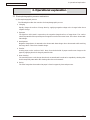
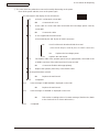
1. Charging
Equally charge the surface of image drum by applying negative voltage to the charged roller due to
negative charge.
2. Exposure
The light from LED Head is exposed on the negative-charged surface of image drum. The surface
electrical potential of the exposed part of image drum surface becomes lower. Then forms electrostatic
latent image.
3. Development
Negative-charged toner is attracted to the electrostatic latent image due to electrostatic while touching
the image drum. Then forms viewable image.
4. Transfer
Overlap paper on the surface of OPC drum, from the backside of paper transfer toner image to the
paper by applying electrical charge by transfer roller.
5. Drum cleaning
The remaining toner on the image drum that is not transferred is made to be equable by cleaning roller.
And is temporarily attracted to the cleaning roller due to electrostatic.
6. Fusing
The toner image that is transferred to paper is fused on paper by heat and pressure.
43984801TH Rev.1
17 /
2. Operational explanation
Oki Data CONFIDENTIAL
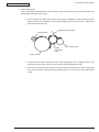
1. Charging
Charge the image drum surface by applying voltage to the charged roller that contacts the image drum
surface.
Charged roller
Power
Image drum
2. Exposure
The light emitting from the LED Head will be exposed to the negative charged image drum. When the
surface electric potential of exposed part of the image drum goes to decrease, the electrostatic latent
image complying with image signal is formed.
Image drum is coated by basic layer (UL), charge generating layer (CGL), charge transferring layer (CTL)
on the basic material aluminum. The thickness of the organic light sensor (OPC) that is consisted by
CTL and CGL is approximate 20µm.
LED head
LED head
Power
Charged roller
Image drum
43984801TH Rev.1
Paper
Image drum
18 /
2. Operational explanation
Oki Data CONFIDENTIAL
3. Image development
Toner is attracted to the electrostatic latent image on the image drum surface, then the electrostatic
latent image changes to toner image.
1 As the roller on the supply spot of toner rotates while scrubbing the image-developing roller,
fiction electricity occurs between the image developing roller and toner; toner is attracted to
the image-developing roller.
Image developing plate
Charged roller
Image
developing
roller
Toner supply roller
Image drum
2. The toner that has been attracted to the image-developing roller is dropped down to the
developing plate to make a thin toner film on the image developing roller side.
3 The toner is attracted by the exposed part (Low electrical potential part) of the image drum
when the image drum contact the image developing roller, so as to see the electrostatic latent
image.
43984801TH Rev.1
19 /
2. Operational explanation
Oki Data CONFIDENTIAL
Note!
The necessary bypass voltage in image processing is impressed on the toner feeding roller
and image developing roller as show below.
While the cover is closed it will be
connected and bias will be applied.
Toner feeding roller
Image developing roller
Basic material
Image drum
43984801TH Rev.1
20 /
2. Operational explanation
Oki Data CONFIDENTIAL
4. Transfer
The transfer roller, which is from conductive sponge material, is created to meet intimate attachment
of image drum roller surface and feeding paper. The feeding paper is set up on the surface of image
drum. Plus charge, which is the converse polarity with toner polarity, is applied from the backside of the
paper.
As high plus voltage is applied to transfer roller from the power supply, the plus charge on the transfer
roller surface is induced and transferred to the paper while the paper contact the transfer roller. The
negative charged toner, which has been attracted to the image drum surface, is transferred to the
surface of feeding paper by the plus charge of the backside of the paper.
Image drum
Paper
Transfer roller
Power
43984801TH Rev.1
21 /
2. Operational explanation
Oki Data CONFIDENTIAL
5. Drum cleaning
1 Cleaning
After the completion of transferring, the remaining toner on the image drum is temporarily attracted
by the electrostatic and the image drum surface is cleaned.
Image drum
Cleaning roller
Power supply
Transferring roller
2 Roller cleaning
In the following case, there is a need of cleaning the charged roller, transfer roller, and cleaning roller.
•
•
•
•
Warming up as switching on the power supply
Warming up after open-close of the cover
In case of termination of printing operation
By periodically change the bias voltage that is implied to each roller during continuous printing,
transfer the attached toner from roller to image drum and then return it to developing device.
43984801TH Rev.1
22 /
2. Operational explanation
Oki Data CONFIDENTIAL
6. Fusing
After the termination of transfer the unsettled toner image is settled to paper by heat and pressure
while passing between Heat roller and Back up roller. Heat roller is Teflon coated and is mounted by
heater that can generate heat (Halogen lamp).
The thermistor that contacts the Heat roller adjusts the Heat roller temperature to the temperature
specified by the menu complying with the paper width. For safety the thermostat shuts off the voltage
supply to the Heater by opening the thermostat in the case of abnormally temperature increasing.
The back up roller is held by the pressure springs on each terminal due to the pressure applied.
Thermostat
Heat roller
Separating clutch
Heater
Thermistor
Feeding paper
Backup roller
Pressuring spring
43984801TH Rev.1
23 /
2. Operational explanation
Oki Data CONFIDENTIAL
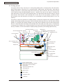
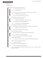
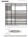
2.2 Printing process
The paper fed from Tray 1 and Tray 2 is conveyed by feeding roller, conveying roller, and resist roller.
When feeding paper is from MPT, it is conveyed by MPT, feeding roller, and resist roller. After that the
feeding paper that is conveyed by image drum and the nip part of transfer roller forms toner image
on the paper through electrophotographic process. And then, the toner on the paper is fused by the
heat and pressure as the fuser unit passing through. The paper that fused the toner image is ejected
from the face down stacker of the ejecting roller. In the case of face up ejecting, it needs to open
the backside cover and install face up stacker. (It is unavailable for duplex printing while it is face up
ejecting.)
The above is about the operations at simplex printing, yet the below explains the operations at duplex
printing. While duplex printing, the paper, which firstly passed through the fuser unit after the backside
printing, is conveyed to the inward of Duplex Unit, by the reverse operation of the second ejecting roller
that is a certain time after removing the first ejecting roller of the paper rear side. Paper, is conveyed by
conveying roller of Duplex Unit, and then merges to the same route with the feeding paper that is from
the tray. Onwards, it is the same with the simplex printing operation by the feeding paper from tray.
Resist roller
Face down stacker
Image
drum
Entrance MPT feeding roller
The 2nd ejecting roller Ejecting
Writing out
sensor lever
sensor lever
Multipurpose tray
sensor lever
Face up stacker
Heat roller
The 1st ejecting roller
Backup roller
Conveying roller
DC motor
Transferring roller
Pick up roller
Duplex unit
Feeding roller
Conveying roller
Tray 1
Conveying roller
Pulse motor
Pick up roller
Feeding roller
Tray 2
2nd tray unit (option)
Paper conveying route
:Driving roller (Continuous rotation)
:Driving roller (Control rotation)
:Driving roller
:Paper level indicator lever
:Indicating lever
:Photo sensor
:Micro switch
:Magnetic clutch
:Solenoid
43984801TH Rev.1
24 /
2. Operational explanation
Oki Data CONFIDENTIAL
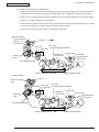
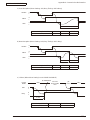
(1) Paper feeding from Tray 1
1. As DC motor rotating (Counterclockwise rotation), if set the paper feeding clutch as ON, as the
paper feeding roller and pick up roller rotating, the paper that is inside the tray is conveyed.
2. The paper is conveyed by the conveying roller. After the entrance sensor level set to be ON, it
bumps into the stopping resist roller, a certain more amount of paper is conveyed. (This corrects
the paper skew.)
3. If set the resist clutch as ON, the paper is conveyed by resist roller.
Resist roller
Writing out sensor lever
Resist clutch
Entrance sensor lever
Conveying roller
DC motor
(Counterclockwise rotation) Pick up roller
Paper feeding roller
Paper
Paper feeding clutch
(2) Paper feeding from Multipurpose tray (MPT)(B420dn, B430d, B430dn)
1. As DC motor rotating (Counterclockwise rotation), if set paper feeding clutch as ON the MPT paper
feeding roller starts to rotate, the paper in the tray is conveyed.
2. After setting the entrance sensor lever as ON, the paper bumps into the stopping resist roller, a certain
more amount of paper is conveyed. (This corrects the skew of paper.)
3. If set the resist clutch as ON, the paper is conveyed by resist roller.
Entrance sensor lever
Paper feeding clutch
Resist clutch
Resist roller
MPT paper feeding roller
Writing out sensor lever
Paper
DV motor
(Counterclockwise rotation)
43984801TH Rev.1
25 /
2. Operational explanation
Oki Data CONFIDENTIAL
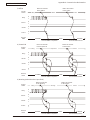
(3) Fuser unit and paper ejecting
1. The fuser unit and eject roller is
2. Simultaneously the eject roller rotates, and then the paper is ejected.
Eject roller
Planet gear
Fuser unit
Heat roller
Paper route
Solenoid
Eject roller
DC motor
(Counterclockwise rotation)
43984801TH Rev.1
26 /
2. Operational explanation
Oki Data CONFIDENTIAL
(4) Paper reversing and paper multi-feeding
1. TRemoving the first eject roller at the rear part of paper and set the solenoid as ON for a while, then the
planet gear starts to move, the second eject roller starts inverse rotating (Counterclockwise rotation).
2. By the inverse rotation of the second eject roller the paper is inversely rotated and conveyed to Duplex.
3. Paper is conveyed by Duplex conveying roller.
4. After setting the entrance sensor lever as ON, paper bumps into the stopped resist roller, still a certain
more amount of paper is conveyed. (This corrects the skew of paper.).
5. If set the Resist clutch as ON, paper is conveyed by Resist roller.
[ Normal rotation ]
The 2nd ejecting
roller
Planet gear
DC motor
Fuser unit
(Counterclockwise rotation)
Heat roller
Resist roller
Writing out
sensor lever
Solenoid
(OFF)
Resist clutch
Resist Entrance
sensor lever
The 1st ejecting roller
Duplex conveying roller Belt
Duplex conveying roller
[ Inverse rotation ]
The 2nd ejecting
roller
Planet gear
Fuser unit
DC motor
(Counterclockwise rotation)
Heat roller
Writing out
sensor lever
Solenoid
(ON)
Resist roller
Resist clutch
Resist Entrance
sensor lever
The 1st ejecting roller
Duplex conveying roller
43984801TH Rev.1
Belt
Duplex conveying roller
27 /
2. Operational explanation
Oki Data CONFIDENTIAL
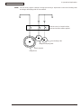
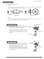
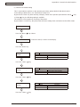
2.3 Toner entrance detection
• Equipment
Toner entrance detecting equipment consists the agitating gear that agitating the agitating bar at a
certain speed and magnet that is on the agitating bar.
Crack part
Magnet
Agitating bar
Agitating gear
• Operation
Detecting the toner low by monitoring the congruous time intervals between the magnet that is set on
the sensor plate and the magnet attached on the agitating bar,
Agitating gear
Operation in toner full status
•
The crack part of agitating gear meshing with the
projection portion of agitating bar, the agitating bar Agitating bar
rotates in accordance with the rotating of gear.
•
Even after the magnet part of the agitating Bar reaches
the highest position, it still rotates at the same speed
by the pressure of the agitating gear due to the toner
resistance.
Sensor plate
Toner sensor
Operation in toner low status
•
When the magnet part of the agitating bar reaches the
highest position, because there is no resistance from
toner, the agitating bar drops earlier than the gear by
the gravity itself, and stops by that status.
For this reason, the time that the magnet of agitating
Bar magnetic attracts the magnet of sensor plate
becomes longer. The toner low status can be inspected
by monitoring this time.
43984801TH Rev.1
Agitating bar
Sensor plate
28 /
2. Operational explanation
Oki Data CONFIDENTIAL
Toner full status
Toner low status
t1 t2
t1,t2: Magnet attracting time
• Toner sensor alarm actuates if there is not any change on toner sensor.
• Toner sensor is not monitored while main (drum) motor is stopping.
43984801TH Rev.1
29 /
3. Parts replacement
Oki Data CONFIDENTIAL
3. Parts replacement
This section explains the replacement procedure of part, assembly, and unit in the working place.
Disassembling procedure relating to reassembling is conducted conversely.
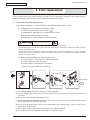
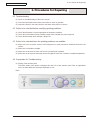
3.1 Preparation for parts replacement
(1) Be sure to unplug the AC cord and interface cable before starting to replace parts.
(a) Unplugging the AC cord by the following procedures.
i) Shut off the power switch of the printer. (「 」)
ii) Unplug the AC insert plug of AC cord from the AC socket.
iii) Remove the earth wire from AC socket.
iv) Unplug the AC cord and interface cable from printer.
Warning
Risk of Electric Shock
There is a risk of electric shock during replacement of the low voltage power supply.
Use insulating gloves or avoid direct contact with any conducting part of the power supply, and caution should be
exercised during replacement.
The capacitor may take one minute to complete discharge after the AC cord is unplugged. Also, there is a possibility
that the capacitor doesn’t discharge because of a breakage of the PCB, etc., so remember the possibility of electric
shock to avoid electric shock.
(b) Reconnecting the printer by the following procedures.
i) Connect the AC cord and interface cable to the printer.
ii) Connect earth wire to the AC socket.
iii) Connect the AC insert plug to the AC socket.
iv) Turn on the power switch of the printer. (「I」)
Shutting
off
Earth terminal
OFF
Reconnecting
ON
Earth cable
(2) Do not disassemble the printer in the case of normal operation.
(3) Do not disengage the part that there is not any necessary to touch. Disassembly should be the
minimum.
(4) Be sure to use the specified maintenance tools.
(5) Be sure to temporarily install the small part such as screw, collar, and so on at its original position during
disassembling because it is easy to be lost.
(6) Do not use the gloves that is easy to occur electrostatic while dealing with IC such as micro-sensor,
ROM, RAM, etc. and PCB.
(7) Do not put the print circuit board on the equipment or on the floor directly.
(8) Do not put the Print Circuit Board on the printer of on the floor directly.
43984801TH Rev.1
30 /
3. Parts replacement
Oki Data CONFIDENTIAL
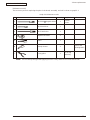
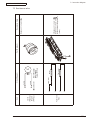
[Maintenance tools]
The necessary tools for replacing the print circuit board, assembly, and unit is shown as graph 3-1.
Graph 3-1 Maintenance tools
No.
Maintenance tools
Quantity
1
No.2-200 + Magnetic driver
1
2
No.3-100 Driver
1
3
No.5-200 Driver
1
4
Digital multi-meter
1
5
Pliers
1
6
Handy cleaner
1
7
E ring pliers
1
Application
Remark
3~5mm
Screw
Refer to the
following Note!
For E ring
removing
Note! Use vacuum by the type that applying to toner. It may cause fire if use normal vacuum.
43984801TH Rev.1
31 /
3. Parts replacement
Oki Data CONFIDENTIAL
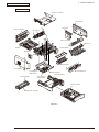
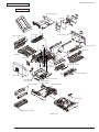
3.2 Parts layout
This section explains the main parts layout of the equipment.
B410d/B410dn
Stacker-Cover-Assy
CU board
Fuser-Assy
Cover-Side-R
Rear-Cover-Assy
A
OPE Cover-Assy
Manual-Assy
A
A’
Duplex
Motor-Fan
GuidePaper-R
Guide-Paper-Duplex
Front-Guide-Assy
Cover-Side-L
A’
Low voltage
power board
Plate-Base-PCB
High voltage
power board
Toner cartridge
Plate-Assy-Base
Paper cassette
Image drum cartridge
Figure 3-1
43984801TH Rev.1
32 /
3. Parts replacement
Oki Data CONFIDENTIAL
B430d/B430dn
Stacker-Cover-Assy
CU board
Fuser-Assy
Cover-Side-R
Rear-Cover-Assy
A
OPE Cover-Assy
A
A’
MPT-Assy
Duplex
Motor-Fan
GuidePaper-R
Guide-Paper-Duplex
Front-Guide-Assy
Cover-Side-L
A’
Low voltage
power board
Toner cartridge
Plate-Base-PCB
High voltage
power board
Plate-Assy-Base
Paper cassette
Image drum cartridge
Figure 3-2
43984801TH Rev.1
33 /
3. Parts replacement
Oki Data CONFIDENTIAL
B420dn
Stacker-Cover-Assy
CU board
Fuser-Assy
Cover-Side-R
Rear-Cover-Assy
A
OPE Cover-Assy
A’
A
MPT-Assy
Duplex
Motor-Fan
GuidePaper-R
Guide-Paper-Duplex
Front-Guide-Assy
Cover-Side-L
A’
Low voltage
power board
Toner cartridge
Plate-Base-PCB
High voltage
power board
Plate-Assy-Base
Paper cassette
Image drum cartridge
Figure 3-3
43984801TH Rev.1
34 /
3. Parts replacement
Oki Data CONFIDENTIAL
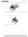
[Base unit]
B410d/B410dn/B430d/B430dn
Photo Interrupter
Gear-Assy-Clutch
Roller-Pick-Up
Roller-Feed-Now
Plate-Base
Guide-Cassette-L
Guide-Cassette-R
Figure 3-4
43984801TH Rev.1
35 /
3. Parts replacement
Oki Data CONFIDENTIAL
[Base unit]
B420dn
Photo Interrupter
Gear-Assy-Clutch
Roller-Pick-Up
Roller-Feed-Now
Plate-Base
Guide-Cassette-L
(530sht)
Guide-Cassette-R
(530sht)
Figure 3-5
43984801TH Rev.1
36 /
3. Parts replacement
Oki Data CONFIDENTIAL
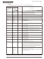
3.3 Parts replacement method
This section explains the replacement method of the parts and assemblies that are shown in the following
disassembling diagram.
About the parts replacement procedure, the parts that are shown by parts number using white number in the
are the RSPL parts.
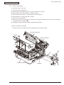
The explaining diagram of parts replacement procedure is B430dn.
Replace part after performing the following operation.
(1)
Unplug the AC power cord from the main unit inlet by the disconnected status of power switch.
(2)
Unplug the interface cable from the main unit.
PR Unit
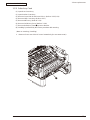
LED Head
(3.3.1)
Cover Side-R
(3.3.3)
Cover Side-L
(3.3.6)
CU Board
(3.3.5)
Rear-Cover-Assy
(3.3.15)
Motor-DC-Main
(3.3.6)
Paper Feeding Roller (Roller-Pick-Up,Roller-Feed-NOW,Roller-Assy-MPT)
(3.3.24)
OPE Cover Assy
(3.3.5)
Stacker-Cover-Assy
(3.3.13)
Ope Board
(3.3.8)
Fuser-Assy
(3.3.14)
MPT-Assy
(In case of B410dn, it is Manual-Assy)
(3.3.9)
Frame-Assy-Lower
(3.3.16)
Front-Guide-Assy
(3.3.10)
Roller-Assy-Feed
(3.3.11)
Guide -Paper-Duplex
(3.3.12)
High/Low voltage Power Board
(3.3.17)
Plate-Brecket-Motor
(3.3.18)
Roller-BackUP
(3.3.19)
Roller-Regist
(3.3.20)
Lever-In-Sensor
(3.3.21)
Lever-Eject-Sensor/Photo-Interrupter
(3.3.22)
Lever-End/Lever-Duplex/
Lever-Cassette/Gear-Assy-Clatch
(3.3.23)
43984801TH Rev.1
37 /
3. Parts replacement
Oki Data CONFIDENTIAL
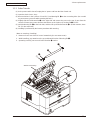
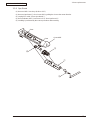
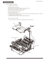
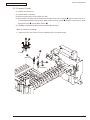
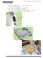
3.3.1 LED Head
(1) Open the Stacker-Cover-Assy
(2) Remove the 2 screws (Black)
. Remove Holder-Head
.
(3) Firstly open Hook A by narrow direction and then remove it. Secondly remove Hook B then remove LED
Assy . (At this moment, the 2 springs can be also removed jointly.)
(4) Remove cable from the connector of LED Assy
.
(5) Installing is performed by the reverse procedure with removing.
Note! Beware of not to touch or press the SLA parts of LED Head directly.
Hook B
Stacker-Cover-Assy
Cable
SLA
(Selfoc Lens Array)
Hook A
43984801TH Rev.1
38 /
3. Parts replacement
Oki Data CONFIDENTIAL
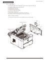
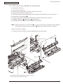
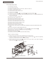
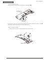
3.3.2 Roller-Transfer
(1) As the power switch shut off, unplug the AC power cord from the inlet of main unit.
(2) Open the Stack-Cover –Assy
(3) Remove latches in the 2 places of Gear-TR ③ and Bearing-TR ❶ on the conversing side. (Do not add
any unnecessary pressure while removing the latch.)
(4) Slightly slide the Roller-transfer ❷ to the right side and remove the post on the top of gear from the
contact of Frame-Assy-Lower. Remove the latches on the 2 places of Gearing-TR ❶ of Gear.
(5) Hold the Bearing-TR ❶ on the both side, and then lift up the Roller-Transfer ❷ . (At this moment, GearTR ③ is also removed.)
(6) Installing is performed by the inverse procedure with removing.
(Note on removing / installing)
1. Beware of not to touch the DC motor inattentively (Do not rotate motor).
2. While installing, pay attention to the up-and-down direction of Bearing-TR ❶.
3. Operating carefully, not to touch Roller-Transfer ❷ surface.
❶
❷
③
❶
Stacker-Cover-Assy
Latch
②
43984801TH Rev.1
39 /
3. Parts replacement
Oki Data CONFIDENTIAL
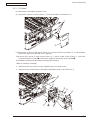
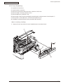
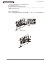
3.3.3 Cover-Side-R
(1) As the power switch shut off, unplug the AC power cord from the inlet of main unit.
(2) Unplug the interface cable from the main unit.
(3) Open the Rear-Cover-Assy.
(4) Open the Stacker-Cover-Assy.
(5) Take out the image drum cartridge.
(6) Remove the Cover-Access ① .
(7) Remove the screw (Black) ② . Remove the Cover-Side-R ③ .
(8) Installing is performed by the inverse procedure with removing.
(Note on removing / installing)
1. Beware of not to touch the DC motor inattentively (Do not rotate motor).
①
Stacker-Cover-Assy
②
③
Rear-Cover-Assy
43984801TH Rev.1
40 /
3. Parts replacement
Oki Data CONFIDENTIAL
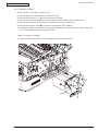
3.3.4 Cover-Side-L
(1) As the power switch shut off, unplug the AC power cord from the inlet of main unit.
(2) Unplug the interface cable from the main unit.
(3) Open the Rear-Cover-Assy.
(4) Open the Stacker-Cover-Assy.
(5) Take out the image drum cartridge.
(6) Remove the 2 screws (Black)
. Remove Cover-Side-L
.
(7) Installing is performed by the inverse procedure with removing.
Note! Attach the Label Motor-Fan on the outside that is obviously to be seen.
Stacker-Cover-Assy
Rear-Cover-Assy
①
②
43984801TH Rev.1
41 /
3. Parts replacement
Oki Data CONFIDENTIAL
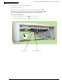
3.3.5 CU Board
(1) Remove the Cover-Side-R. (Refer to 3.3.3)
(2) Remove the 4 pieces of screws (Silver) ① . Remove the Plate-Cover-Shield-CU ② .
①
②
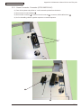
(3) Remove the 2 pieces of big screws (Silver) ③ . Remove the Film-Core-Holder ④ . In the meantime
remove the cable connector (with core) ⑤ together.
(4) Remove the 2 pieces of small screws (Silver) ⑥ , 2 pieces of big screws (Silver) ⑦ , and cable
connector from the CU board ❽ . Remove the Spring-FG-Solenoid ⑨ and CU board ❽ .
(5) Installing is performed by the inverse procedure with removing.
(Note on removing / installing)
1. Beware of not to touch the DC motor inattentively (Do not rotate motor).
2. Beware of not to tuck down the cable while installing the Plate-Cover-Shield-CU ② .
⑥
⑤
⑨
③
④
⑦
DC motor
⑦
43984801TH Rev.1
❽
⑤
③
42 /
3. Parts replacement
Oki Data CONFIDENTIAL
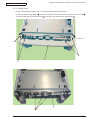
3.3.6 Motor-DC-Main
(1) Remove the Cover-Side-R. (Refer to 3.3.3)
(2) Remove the Plate-Cover-Shield-CU. (Refer to 3.3.5(2))
(3) Remove the connector ① of Motor-DC-Main from CU board.
(4) Cut the TY-RAP that is bundling the cable of Motor-DC-Main and the cable of Resist clutch.
(5) Remove the 3 pieces of screws (Silver) ② and the 1 piece of screw (Black) ③ .
(6) Remove the Motor-DC-Main ❹ . Unplug the cable from the Piece-Guide ⑤ .
(7) Installing procedure is performed by the opposite order with removing. Bundle the cable of Motor-DCMain and the cable of Resistor clutch by TY-RAP.
(Note on removing / installing)
1. Beware of not to touch the DC motor inattentively (Do not rotate motor).
①
②
③
❹
Cable
⑤
43984801TH Rev.1
43 /
3. Parts replacement
Oki Data CONFIDENTIAL
3.3.7 OPE Cover-Assy
(1) Open the Rear-Cover-Assy.
(2) Open the Stacker-Cover-Assy.
(3) Remove the Cover-Side-R and Cover –Side-L. (Refer to 3.3.3/3.3.4)
(4) Remove the Plate-Cover-Shield-CU. (Refer to 3.3.5(2))
(5) Remove the screw (Silver) ① . Remove the Film-Core-Holder ② .
(6) Remove the FFC cable ③ from the CU board.
(7) Open the Cover-Assy-MPT.
(8) Pull Claw A by the arrow direction. Remove the clamp by pushing Claw B as the arrow direction.
Remove the OPE Cover-Assy ❹ .
(9) Installing is performed by the reverse procedure with removing.
(Note on removing / installing)
1. Beware of not to touch the DC motor inattentively (Do not rotate motor).
Stacker-Cover-Assy
Claw B
❹
Rear-Cover-Assy
Claw A
Claw B
③
Cover-Assy-MPT
43984801TH Rev.1
CU board
②
①
44 /
3. Parts replacement
Oki Data CONFIDENTIAL
3.3.8 Ope-Board
(1) Remove OPE Cover-Assy. (Refer to 3.3.7)
(2) Remove Ope-Board ① from Cover-OPE by pulling the claw as the arrow direction.
(3) Unplug FFC cable ② from Ope-Board ① .
(4) Remove Button-KEY ③ and Lens-LCD ④ from Ope-Board ① .
(5) Installing is performed by the reverse procedure with removing.
Claw
Claw
Cover-OPE
③
④
①
②
43984801TH Rev.1
45 /
3. Parts replacement
Oki Data CONFIDENTIAL
3.3.9 MPT-Assy (In case of B410dn, it is Manual-Assy)
(1) Open Rear-Cover-Assy.
(2) Open Stacker-Cover-Assy.
(3) Remove Cover-Side-R and Cover-Side-L. (Refer to 3.3.3/3.3.4)
(4) Remove OPE Cover-Assy. (Refer to 3.3.7)
(5) Remove the clamp of claw by pushing by arrow A direction, and then remove Cover-Lever-Lock ① .
(6) Remove the 2 screws (Black)
.
(7) Open the Frame-Assy-Lower by arrow B direction, and then remove Lever-Lock-Top ③ .
(8) Holding up MPT-Assy
(Manual-Assy
) and remove it.
(9) Installing is performed by the inverse procedure with removing.
Note! While removing the Lever-Lock-Top
, it is easy to remove it by inserting the driver between
the Frame-Assy-Lower and Lever-Lock-Top
and press the driver by Arrow C direction.
(Note on removing / installing)
1. Beware of not to touch the DC motor inattentively (Do not rotate motor).
③
C
Driver
A
①
②
Frame-Assy-Lower
③
②
A
B
②
❹ʼ
②
B
❹
Pay attention not to let Separating- Pad- Assy pop out to
your front side while installing MPT-Assy.
43984801TH Rev.1
46 /
3. Parts replacement
Oki Data CONFIDENTIAL
3.3.10 Front-Guide-Assy
(1) Open Rear-Cover-Assy.
(2) Open Stacker-Cover-Assy.
(3) Remove Cover-Side-R and Cover-Side-L. (Refer to 3.3.3/3.3.4)
(4) Remove OPE Cover-Assy. (Refer to 3.3.7)
(5) Remove MPT-Assy. (Refer to 3.3.9)
(6) Remove the clamp of claw by pushing by arrow direction, and then remove Cover-Paper-R ① .
(7) Remove the 2 screws (Black) ② . Remove Front-Guide-Assy ③ .
(8) Installing is performed by the inverse procedure with removing.
(Note on removing / installing)
1. Beware of not to touch the DC motor inattentively (Do not rotate motor).
①
②
②
③
43984801TH Rev.1
47 /
3. Parts replacement
Oki Data CONFIDENTIAL
3.3.11 Roller-Assy-Feed
(1) Open Rear-Cover-Assy.
(2) Open Stacker-Cover-Assy.
(3) Remove Cover-Side-R and Cover-Side-L. (Refer to 3.3.3/3.3.4)
(4) Remove OPE Cover-Assy. (Refer to 3.3.7)
(5) Remove MPT-Assy. (Refer to 3.3.9)
(6) Remove Guide-Assy-Front. (Refer to 3.3.10)
(7) Remove Roller-Assy-Feed ❶ by arrow direction.
(8) Installing is performed by the inverse procedure with removing.
(Note on removing / installing)
1. Beware of not to touch the DC motor inattentively (Do not rotate motor).
❶
43984801TH Rev.1
48 /
3. Parts replacement
Oki Data CONFIDENTIAL
3.3.12 Guide-Paper-Duplex
(1) Open the Rear-Cover-Assy.
(2) Open the Stacker-Cover-Assy.
(3) Remove Cover-Side-R and Cover-Side-L. (Refer to 3.3.3/3.3.4)
(4) Remove OPE Cover-Assy. (Refer to 3.3.7)
(5) Remove MPT-Assy. (Refer to 3.3.9)
(6) Remove Front-Guide-Assy. (Refer to 3.3.10)
(7) Remove Roller-Assy-Feed. (Refer to 3.3.11)
(8) Remove Duplex-Assy.
(9) Remove the 2 screws (Black) ① . Remove Guide-Paper-Duplex ② .
(10) Installing is performed by the reverse procedure with removing.
(Note on removing / installing)
1. Beware of not to touch the DC motor inattentively (Do not rotate motor).
①
①
②
43984801TH Rev.1
49 /
3. Parts replacement
Oki Data CONFIDENTIAL
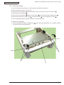
3.3.13 Stacker-Cover-Assy
(1) Open the Rear-Cover-Assy.
(2) Open the Stacker-Cover-Assy.
(3) Remove Cover-Side-R and Cover-Side-L. (Refer to 3.3.3/3.3.4)
(4) Remove Plate-Cover-Shield-CU. (Refer to 3.3.5(2))
(5) Remove film-Core-Holder. (Refer to 3.3.7(5))
(6) Remove LED cable from CU board.
(7) Remove the screw (Silver) ① .
(8) Open the Stacker-Cover-Assy ② by the arrow direction and remove Stacker-Cover-Assy ② from the
supporting point of Frame-Assy-Lower.
(9) Installing is performed by the reverse procedure with removing.
(Note on removing / installing)
1. Beware of not to touch the DC motor inattentively (Do not rotate motor).
②
①
Frame-Assy-Lower
LED cable
CU board
43984801TH Rev.1
50 /
3. Parts replacement
Oki Data CONFIDENTIAL
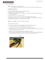
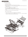
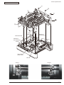
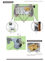
3.3.14 Fuser-Assy
Note! Replace the Fuser-Assy by Assy unit.
It is forbidden for disassembling the Fuser-Assy, also, reusing the disassembled Fuser-Assy.
(1) Open Rear-Cover-Assy.
(2) Open Stacker-Cover-Assy.
(3) Remove Cover-Side-R and Cover-Side-L. (Refer to 3.3.3/3.3.4)
(4) Remove Stacker-Cover-Assy. (Refer to 3.3.13)
(5) Unplug connector (Motor-Fan) ① and connector (Semester) ② from high voltage power board, and
remove Piece-Guide ③ .
(6) Remove Motor-Fan ④ . Remove Piece-Guide ⑤ .
(7) Unplug the connector ⑥ of Fuser-Assy, which is at the back side of Piece-Guide ⑤ .
(8) Remove the 4 screws (Silver) ⑦ . Remove the Fuser-Assy ❽ by bowing down the lock at the left side.
(9) Installing is performed by the inverse procedure with removing.
Note! Fuser-Assy ❽ may be really hot, beware of handling.
(Note on removing / installing)
1. Install the screw (Silver) ⑦ in its original groove. (Do not make new screw tap.)
2. Do not add excessive pressure while tightening the screw (Silver) ⑦ .
3. Beware of not to touch the DC motor inattentively (Do not rotate the motor).
4. Install the Motor-Fan ④ by combining the arrow indicating Fan flowing direction and the arrow
direction that is incused on the Fan-Lower.
5. Beware of not to deform the thermistor while replacing the Fuser-Assy.
6. While removing or installing FAN, do not press impeller of the FAN as shown by the following photo.
In case of the impeller unfastened by mistake, do not reuse it and install a new FAN.
Impera
43984801TH Rev.1
51 /
3. Parts replacement
Oki Data CONFIDENTIAL
⑦
❽
⑥
②
Thermistor
Arrow
⑤
④
③
①
High voltage
power board
43984801TH Rev.1
Connector for Thermistor
Connector for FAN
52 /
3. Parts replacement
Oki Data CONFIDENTIAL
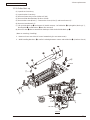
3.3.15 Rear-Cover-Assy
(1) Open Rear-Cover-Assy.
(2) Open Stacker-Cover-Assy.
(3) Remove Cover-Side-R. Remove Cover-Side-L. (Refer to 3.3.3/3.3.4)
(4) Remove Cover-Face Up-A ① from the supporting point with opening the right side supporting point part
of Rear-Cover-Assy.
(5) Remove the 2 screws (Black) ② . Remove Plate-Solenoid ③ .
(6) Remove Solenoid ❹ from Rear-Cover-Assy ❺ .
Because the plunger is not fixed, beware of not to drop or lose it.
(7) Remove Rear-Cover-Assy by bowing down the supporting point part of Rear-Cover-Assy to the inner
side.
(8) Installing is performed by the inverse procedure with removing.
(Note on removing / installing)
1. Beware of not to touch the DC motor inattentively (Do not rotate motor).
2. About the installing of Rear-Cover-Assy ❺ , remove Cover-Face Up-A ① , make the supporting
point part to a bowed situation and then perform installing.
①
❺
Plunger
❹
②
③
②
Supprting point
43984801TH Rev.1
53 /
3. Parts replacement
Oki Data CONFIDENTIAL
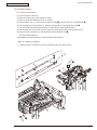
3.3.16 Frame-Assy-Lower
(1) Open Rear-Cover-Assy.
(2) Open Stacker-Cover-Assy.
(3) Remove Cover-Side-R. Remove Cover-Side-L. (Refer to 3.3.3/3.3.4)
(4) Remove CU Board. (Refer to 3.3.5)
(5) Remove Motor-DC-Main. (Refer to 3.3.6)
(6) Remove Piece-Guide
.
(7) Remove the 3 screw (Silver)
and screw (Black)
. Remove Plate-Shield-CU
.
(8) Pass the connector of Low Voltage Power Board through the Portion A of Plate-Bracket-Motor from
above to the downward.
(9) Remove OPE Cover-Assy. (Refer 3.3.7)
(10) Remove MPT-Assy. (Refer to 3.3.9)
(11) Remove Front-Guide-Assy. (Refer to 3.3.10)
(12) Remove Roller-Assy-Feed. (Refer to 3.3.11)
(13) Remove Guide-Paper-Duplex. (Refer to 3.3.12)
(14) Remove Stacker-Cover-Assy. (Refer to 3.3.13)
(15) Remove Fuser-Assy. (Refer to 3.3.14)
(16) Remove Rear-Cover-Assy. (Refer to 3.3.15)
(17) Remove all the cable from Hook A of Holder-SNS, extend them and put on the right front side of the printer.
(18) Remove connector B from high voltage power board.
(19) Remove the 4 long screws (Silver)
, the 4 screws (Black)
, the short screw (Silver)
.
(20) Remove Hook C and Hook D of Plate-Base-PCB using minus driver.
(21) Remove Frame-Assy-Lower
.
(22) Installing is performed by the inverse procedure with removing.
(Note on removing / installing)
1. Beware of not to touch the DC motor inattentively (Do not rotate motor).
2. About the installing of Rear-Cover-Assy
, remove Cover-Face Up-A
point part to a bowed situation and then perform installing.
, make the supporting
, beware of not to tuck Cable Ⓕ and Cable Ⓖ between
and Plate-Base-PCB.
3. While installing Frame-Assy-Lower
Frame-Assy-Lower
②
Supporting point ④
③
A
①
43984801TH Rev.1
Plate-Braket-Motor
②
54 /
3. Parts replacement
Oki Data CONFIDENTIAL
②
③
①
②
❹
②
Connector Ⓑ
②
Cable Ⓕ
Cable G
Attention to
wire interwining
Plate-Base-PCB
Hook Ⓓ
Attention to
wire interwining
Hook Ⓐ
Cable Ⓔ
High voltage
power board
Hook Ⓒ
Hook C
43984801TH Rev.1
Hook D
55 /
3. Parts replacement
Oki Data CONFIDENTIAL
3.3.17 High voltage / Low voltage power board
Warning
Risk of Electric Shock
There is a risk of electric shock during replacement of the low voltage power supply.
Use insulating gloves or avoid direct contact with any conducting part of the power supply, and caution should be
exercised during replacement.
The capacitor may take one minute to complete discharge after the AC cord is unplugged. Also, there is a possibility
that the capacitor doesn’t discharge because of a breakage of the PCB, etc., so remember the possibility of electric
shock to avoid electric shock.
(1) Open Rear-Cover-Assy.
(2) Open Stacker-Cover-Assy.
(3) Remove Frame-Assy-Lower. (Refer to 3.3.16)
(4) Remove the big screw (Silver) ① . Remove the earth wire.
(5) Remove the AC socket ② and power switch ③ . Remove Guide-Cassette-L.
(6) Remove the 3 small screws (Silver) ④ . Remove Low voltage power board ❺ .
(7) Remove the 4 small screws (Silver) ⑥ . Remove High voltage power board ❼ .
(8) Installing is performed by the inverse procedure with removing.
(Note on removing / installing)
1. Beware of not to touch the DC motor inattentively (Do not rotate motor).
2. Do not apply excessive pressure to the power switch ③ .
3. While installing High voltage / Low voltage power board to the Plate-Base-PCB, do not deform the
Plate-Base-PCB.
②
④
❺
⑥
Short plug connector
100/120V Printer : Installation
230V Printer : De-installation rejection
③
⑥
PCB-Assy
①
Pay attention not
to scratch the FFC.
❼
Earth wire
Pay at tention to the
b e n d i n g d ire c t i o n a s
the text printed side up.
Plate-Base-PCB
Guide-Cassette-L
43984801TH Rev.1
56 /
3. Parts replacement
Oki Data CONFIDENTIAL
3.3.18 Plate-Bracket-Motor
(1) Open Rear-Cover-Assy.
(2) Open Stacker-Cover-Assy.
(3) Remove Motor-DC-Main. (Refer to 3.3.6)
(4) Remove Frame-Assy-Lower. (Refer to 3.3.16)
(5) Assemble Frame-Assy-Lower as the diagram.
(6) Remove the 4 screws (Black) ① . Remove Plate-Bracket-Motor ② .
(7) Installing is performed by the inverse procedure with removing.
(Note on removing / installing)
1. Beware of not to touch the DC motor inattentively (Do not rotate motor).
2. While installing beware of not to tuck Cable between Frame-Assy-Lower and Plate-Bracket-Motor.
3. Beware of not to drop the gear or scratch the surface of gear.
4. Because Gear-Idle-Drum-Z24-48 and Gear-Idle-Drum-Z27-82 are high precision gear, beware of
handling them with particular care.
①
Gear-Idle-Drum-Z27-82
Gear-Idle-Drum-Z24-48
②
Frame-Assy-Lower
43984801TH Rev.1
57 /
3. Parts replacement
Oki Data CONFIDENTIAL
3.3.19 Roller-Back up
(1) Open Rear-Cover-Assy.
(2) Open Stacker-Cover-Assy.
(3) Remove Frame-Assy-Lower. (Refer to 3.3.16)
(4) Remove Plate-Bracket-Motor. (Refer to 3.3.18)
(5) Remove the screw (Black) ① . Remove the screw (Color) ② and Lever-Reset-L ③ .
(6) Remove Lever-Reset-R ④ .
(7) Lift up Roller-Back up ❺ and remove it. (At this moment, 2 of Holder-BU ❻ , Spring-Bias (Back up) ⑦ ,
Bearing-Ball ❽ , and Washer-C ❾ are also removed.)
(8) Remove color ❿ that are attached on both tops of the shaft of Roller-Back up ❺ .
(Note on removing / installing)
1. Beware of not to touch the DC motor inattentively (Do not rotate motor).
2. While installing Washer-C ❾, confirm it existing between contact and Holder-BU ❻. (Refer to View A)
❿
❺
❻
❾
❽
⑦
❿
④
❽
View A
❻
⑦
①
②
❾
③
Contact
View A
43984801TH Rev.1
58 /
3. Parts replacement
Oki Data CONFIDENTIAL
3.3.20 Roller-Resist
(1) Open Rear-Cover-Assy.
(2) Open Stacker-Cover-Assy.
(3) Remove Frame-Assy-Lower. (Refer to 3.3.16)
(4) Remove Plate-Bracket-Motor. (Refer to 3.3.18)
(5) Remove the E ring ① . Remove the Gear-Assy-Clutch ❷ , Spacer-Clutch ③ and Bearing-R ❹ .
(6) Remove the lock of Gear-Resist ⑤ . Remove Gear-Resist ⑤ , Bearing-Resist-Assy ❻.
(7) Lift up the left side of Roller-Resist-Assy ⑦ and remove it at the arrow direction.
(8) Remove the lock of Gear-Pressure ⑧ . Remove Gear-Pressure ⑧ from Roller-Pressure ⑨.
(9) Remove Plate-Contact-PA ⑪ and Holder-Resist from Roller-Resist ❿ .
Remove Holder-Resist ⑬ .
(10) Installing is performed by the inverse procedure with removing.
(Note on removing / installing)
1. Beware of not to touch the DC motor inattentively (Do not rotate motor).
⑦
⑪
①
❷
⑬
⑨
❿
❹
③
⑧
⑫
⑦
⑤
❻
43984801TH Rev.1
59 /
3. Parts replacement
Oki Data CONFIDENTIAL
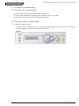
3.3.21 Lever-In-Sensor
(1) Open Rear-Cover-Assy.
(2) Open Stacker-Cover-Assy.
(3) Remove Frame-Assy-Lower. (Refer to 3.3.16)
(4) Remove the 2 Lever-In-Sensor (Entrance and Paper). Press the Clamp of ❶ , press Lever-In-Sensor ①
as up direction and then remove them. While remove Lever-In-Sensor ❶ , beware of not to loss or break
Spring-Sensor-In ❷ , Spring-Write-Sensor ❸ .
(5) Installing is performed by the inverse procedure with removing.
(Note on removing / installing)
1. Beware of not to touch the DC motor inattentively (Do not rotate motor).
❶
Clamp
❸
❶
(Paper)
❶
❷
(Entrance)
43984801TH Rev.1
60 /
3. Parts replacement
Oki Data CONFIDENTIAL
3.2.22 Lever-Eject-Sensor/Photo-Interrupter
(1) Open Rear-Cover-Assy.
(2) Open Stacker-Cover-Assy.
(3) Remove Frame-Assy-Lower. (Refer to 3.3.16)
(4) Press the clamp of Lever-Eject-Sensor(Exit)❶ . Press Lever-Eject-Sensor ❶ as down direction and
remove it. While remove Lever-Eject-Sensor ❶ , beware of not to loss or break Spring-SNS ❷ .
(5) Press the claw of Frame-Assy-Lower as the arrow direction. Remove Photo-Interrupter ③ by down
direction.
(6) Installing is performed by the inverse procedure with removing.
(Note on removing / installing)
1. Beware of not to touch the DC motor inattentively (Do not rotate motor).
Clamp
❶
Frame-Assy-Lower
③
③
❶
❷
Frame-Assy-Lower
43984801TH Rev.1
61 /
3. Parts replacement
Oki Data CONFIDENTIAL
3.3.23 Lever-End/Lever-Duplex/Lever-Cassette/Gear-Assy-Clatch
(1) Remove Frame-Assy-Lower and PCB-Assy.
(2) Press claw Ⓐ by the arrow direction. Remove Holder-SNS ①.
(3) Press the clamp of Lever-End ② by the up direction and then remove it.
(4) Press the clamp of Lever-Duplex ③ by the up direction and then remove it.
(5) Press the clamp of Lever-Cassette ④ by the up direction and then remove it.
(6) Open claw Ⓑ and remove Photo-Interrupter ❺.
(7) Hold up Plate-Base-Assy ⑥ from the claw of Guide-Cassette-L, Guide-Cassette-R and remove PlateBase-Assy ⑥ .
④
❺
②
③
①
Claw A
Claw B
Claw
⑥
Guide-Cassette-R
Claw
Guide-Cassette-L
43984801TH Rev.1
62 /
3. Parts replacement
Oki Data CONFIDENTIAL
・ Remove Feed-Roller / Clutch.
(8) Press Claw D by the arrow direction an d remove Feed-Roller-NO ❿ .
Plate-Base-Assy
❿
Claw D
(9) Remove the 2 of E ring ⑪, Slide Hopping-shaft by the arrow direction and remove Gear-Assy-Clutch ⓬.
(10) Installing is performed by the inverse procedure with removing.
(Note on removing / installing)
1. Beware of not to touch the DC motor inattentively (Do not rotate motor).
⑪
⓬
⑪
Hopping-shaft
43984801TH Rev.1
63 /
3. Parts replacement
Oki Data CONFIDENTIAL
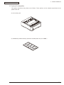
3.3.24 Paper feeding roller (Roller-Pick-Up,Roller-Feed-NOW,Roller-Assy-MPT)
・ In the case of Tray 1, Tray (Option)
(1) Shut off the power of Printer. Draw and take off the Paper Cassette of Tray.
(2) Widen the claw of the 2 of Paper feeding roller ❶ and remove them.
(Note on removing / installing)
1. While install the Paper feeding roller(With Gear:Roller-Pick-Up)、be sure to press in it till the
setting sound at the deep side shaft can be heard as the confirmation of fixing.
2. While install the Paper feeding roller(Without Gear:Roller-Feed-NOW)、be sure to press in it till
the setting sound at the front side shaft can be heard as the confirmation of fixing.
Paper cassette
Paper feeding roller
(Without gear : Roller-Feed-NOW)
❶
Paper feeding roller
(With gear : Roller-Pick-Up)
43984801TH Rev.1
64 /
3. Parts replacement
Oki Data CONFIDENTIAL
・ In the case of Multi-purpose Tray (B420dn, B430d, B430dn)
(1) Shut off the power of Printer.
(2) Open Multi-purpose Tray, widen paper supporter.
(3) Open the cover of Paper feeding roller of Multi-purpose Tray by up direction. Remove Roller-Assy-MPT
❶ by rolling it to the near side.
(Note on removing / installing)
1. While install the Paper feeding roller (Roller-Assy-MPT) ❶ 、be sure to press it into the depths of
the shaft and confirm whether it is fixed.
Paper feeding roller cover
❶
Multipurpose tray
❶
43984801TH Rev.1
65 /
4. ADJUSTMENT
Oki Data CONFIDENTIAL
4. ADJUSTMENT
This chapter provides explains relating to the adjustment that is necessary while replacing part. Adjustment
is performed by modifying the value of parameter that is set on the EEPROM of main PCB board. Parameter
can be set by key operation that is from the operator panel. There are 3 kinds of maintenance mode (menu)
on this printer. While replacing part it is need to choose one of the mode.
4.1 Category and function of maintenance mode
• Maintenance mode can be divided into User maintenance mode that is released to user, Engine
Maintenance Mode and System Maintenance Mode that are not released to user but for the only
use of maintenance personnel.
• For renewing each category, push the button of "MENU ▲ " and "MENU ▼ " . After renewing the
last category, it returns to the initial category.
• If want the displayed function to be effective, push the「SETUP」button.
• For terminating the mode that is in category displaying, push the key of「ON LINE」and return to
operation mode.
4.4.1 User maintenance mode (Administrator Menu)
For Administrator Menu, push the button of「SETUP」and power Switch simultaneously.
After the category has been displayed, let go of the button "SETUP".
Administrator Menu has the following function.
Operation panel display
Category
OP MENU
Default
value
Function
* Only English is supported for panel display
ALL CATEGORY ENABLE
DISABLE
*
INFORMATION
MENU
ENABLE
DISABLE
*
SHUTDOWN
MENU
ENABLE
DISABLE
*
PRINT MENU
ENABLE
DISABLE
*
MEDIA MENU
ENABLE
DISABLE
*
SYS CONFIG
MENU
ENABLE
DISABLE
*
PCL
EMULATION
ENABLE
DISABLE
*
PPR
EMULATION
ENABLE
DISABLE
*
Sets category ALL Enable/Disable of User Menu. If
set to invalidation, user menu wont to be display. The
following setting item is not displayed if it is invalid.
When doing panel lock, must invalidate this menu.
ISetting validation / Invalidation of INFORMATION
MENU category. If invalidate it the INFORMATION
MENU category of user menu is not displayed.
Set Category SHUTDOWN MENU Enable/Disable.
Set to Disable, Category SHUTDOWN MENU of User
Menu is not displayed.
Set Category PRINT MENU Enable/Disable.
Set to Disable, Category PRINT MENU of User Menu
is not displayed.
Set Category MEDIA MENU Enable/Disable.
Set to Disable, Category MEDIA MENU of User Menu
is not displayed.
Set Category SYSTEM CONFIG MENU Enable/
Disable.
Set to Disable, Category SYSTEM CONFIG MENU
OF User Menu is not displayed.
Set Category PCL EMULATION MENU Enable/
Disable.
Set to Disable, Category PCL EMULATION MENU of
User Menu is not displayed.
Set Category PPR EMULATION MENU Enable/
Disable.
Set to Disable, Category PPR EMULATION MENU of
User Menu is not displayed. Except Japan Oriented.
[Display Condition]
"SYSTEM MAINTENANCE"-"PERSONALITY"-"IBM
PPR III XL" is ENABLE.
Setting item
(Upper case)
43984801TH Rev.1
Setting item
(Lower case)
66 /
4. ADJUSTMENT
Oki Data CONFIDENTIAL
Operation panel display
Category
OP MENU
CONFIG
MENU
Default
value
Function
* Only English is supported for panel display
FX EMULATION ENABLE
DISABLE
*
ESC/P
EMULATION
ENABLE
DISABLE
*
PARALLEL
MENU
ENABLE
DISABLE
*
USB MENU
ENABLE
DISABLE
*
NETWORK
MENU
ENABLE
DISABLE
*
Set Category FX EMULATION MENU ENABLE/
DISABLE.
Set to DISABLE, Category FX EMULATION MENU of
User Menu is not displayed. Except Japan Oriented.
[Display Condition]
"SYSTEM MAINTENANCE"-"PERSONALITY""EPSON FX" is ENABLE.
Set Category ESC/P MENU ENABLE/DISABLE.
Set to DISABLE, Category ESC/P MENU of User
Menu is not displayed. Only displayed as Japan
domestic oriented.
[Display Condition]
"SYSTEM MAINTENANCE"-"PERSONALITY"-"ESC/
P" is ENABLE.
Set Category PARALLEL MENU ENABLE/DISABLE.
Set to DISABLE, Category PARALLEL MENU of User
Menu is not displayed.
Set Category USB MENU ENABLE/DISABLE.
Set to DISABLE, Category USB MENU of User Menu
is not displayed.
Set Category NETWORK MENU ENABLE/DISABLE.
Set to DISABLE, Category NETWORK MENU of User
Menu is not displayed.
[Display Condition]
NIC full assembled
Set Category MEMORY MENU ENABLE/DISABLE.
Set to DISABLE, Category MEMORY MENU OF User
Menu is not displayed.
Set Category SYS ADJUST MENU ENABLE/
DISABLE.
Set to DISABLE, Category SYS ADJUST MENU of
User Menu is not displayed.
Set Category MAINTENANCE MENU ENABLE/
DISABLE.
Set to DISABLE, Category MAINTENANCE MENU of
User Menu is not displayed.
Set Category USAGE MENU ENABLE/DISABLE.
Set to DISABLE, Category USAGE MENU of User
Menu is not displayed.
Set Function MENU LOCKOUT ENABLE/DISABLE.
Set to DISABLE, Category PASSWORD, Category
CHANGE PASSWORD of User Menu is not displayed.
The Initial Value of PASSWORD is "aaaa".
Set Function PANEL LOCKOUT ENABLE/DISABLE.
Set to ENABLE, on the panel only "ONLINE" switch is
ENABLE, it is not able to display MENU.
Set LED ILLUMINATION CONTROL at the occurrence
of NEAR LIFE WARNING of toner and drum.
When it is ENABLE, Attention LED illuminating.
When it is DISABLE, Attention LED non-illuminating.
Once it became life warning error, the status of
temporary retrieving as the cover opening or closing
(LIFE WARNING) is excluded.
Setting item
(Upper case)
Setting item
(Lower case)
MEMORY MENU ENABLE
DISABLE
*
SYS ADJUST
MENU
*
ENABLE
DISABLE
MAINTENANCE ENABLE
MENU
DISABLE
*
USAGE MENU
ENABLE
DISABLE
*
MENU
LOCKOUT
ENABLE
DISABLE
*
PANEL
LOCKOUT
ENABLE
DISABLE
*
NEARLIFE LED
ENABLE
DISABLE
43984801TH Rev.1
*
67 /
4. ADJUSTMENT
Oki Data CONFIDENTIAL
Operation panel display
Category
Setting item
(Upper case)
Setting item
(Lower case)
Default
value
Function
* Only English is supported for panel display
*
Initialize resident FLASH.
Press Enter switch then the following confirming
message is displayed.
ARE YOU SURE? EXECUTE OR NOT?
YES / NO
YES / NO
If NO is chosen, it returns to the previous menu
display.
If YES is chosen, it reboots automatically and executes
the initialization of Flash Memory.
[Display condition]
"ADMIN MENU"-"FILE SYS MAINTE2"-"INITIAL
LOCK" is NO.
Do not allow to modify setting accompanied by the
initialization of Block Device (FLASH).
If set this menu to YES, item "ADMIN MENU", "FILE
SYS MAINTE1" is not displayed on the operation
panel.
[Display condition]
"PRINT ACCUMULATING"-"ACCUMULATING
RESULT PRINT" of User Menu is DISABLE.
As setting TYPE 1, the selecting number of level
1 operator tray is enable from 1, yet it is from 0 as
setting TYPE 2,
Only B430/B440 series is displayed.
Set Pn specified by MANUAL in CSF CONTROL
CONMENT OF MANUAL-1 ID No.FX/PPR/ESCP
Emu(ESC EM Pn).
Default value: Japan oriented is "0", Except Japan
oriented is "2".
Set Pn specified by MANUAL in CSF CONTROL
CONMENT OF MANUAL-2 ID No.FX/PPR/ESCP
Emu(ESC EM Pn).
*
Set Pn specified by TRAYO (mp Tray) in the MP Tray
ID No. FX/PPR Emu (ESC EM Pn).
Only B430/B440 series is displayed.
FILE SYS
MAINTE1
FLASH
INITIALIZE
EXECUTE
-
FILE SYS
MAINTE2
INITIAL LOCK
YES
NO
*
PS MENU
L1 TRAY
TYPE1
TYPE2
*
SIDM
MENU
SIDM MANUAL
ID#
0
~
2
~
9
SIDM MANUAL 0
2 ID#
~
3
~
9
SIDM MP TRAY 0
ID#
~
4
~
9
SIDM TRAY1 ID# 0
1
~
9
SIDM TRAY2
0
ID#
~
2
~
5
~
9
LANGUAGE LANG
EXECUTE
MENU
INITIALIZE
43984801TH Rev.1
*J
*E
*
*J
*E
-
Set Pn specified by TRAY 1 in CSF CONTROL
DEMMAND of Tray 1 ID No. FX/PPR/ESCP Emu (ESC
EM Pn).
Set Pn specified by TRAY 1 in CSF CONTROL
DEMMAND (ESC EM Pn) of Tray 2 ID No.FX/PPR/
ESCP Emu.
Default Value: Japan oriented is "2", Except Japan
oriented is 5.
[Display condition]
Tray 2 implementation
Initialize (Delete) LED message file that is loaded on
FLASH.
Press Enter switch then the following message is
displayed.
ARE YOU SURE?
YES / NO
If NO is selected, return to original MENU display.
If YES is selected, immediately remove the MENU and
starts to delete operation after reboot.
Only support Multi-language model.
68 /
4. ADJUSTMENT
Oki Data CONFIDENTIAL
• User maintenance mode menu chart
“Display Indicating”
OP MENU
Press Key
“SETTING”
Press Key “MENU▲” “MENU▼” and move
ALL CATEGORY
ENABLE
ALL CATEGORY
* Select by Key
DISABLE
“SETTING” and
press key
“MENU▲” “MENU▼”
INFORMATION MENU
ENABLE
* Select by Key
INFORMATION MENU
DISABLE
Set ENABLE/DISABLE for INFORMATION
MENU category. Select by key “MENU▲”
“MENU▼” .
SHUTDOWN MENU
ENABLE
* Select by Key
SHUTDOWN MENU
DISABLE
Set ENABLE/DISABLE for SHUTDOWN
MENU category. Select by key “MENU▲”
“MENU▼” .
PRINT MENU
ENABLE
* Select by Key
PRINT MENU
DISABLE
Set ENABLE/DISABLE for PRINT MENU
category. Select by key “MENU▲” “MENU▼” .
MEDIA MENU
ENABLE
* Select by Key
MEDIA MENU
DISABLE
Set ENABLE/DISABLE for MEDIA MENU
category. Select by key “MENU▲” “MENU▼” .
SYS CONFIG MENU
ENABLE
* Select by Key
SYS CONFIG MENU
DISABLE
Set ENABLE/DISABLE for SYS CONFIG
MENU category. Select by key “MENU▲”
“MENU▼” .
PCL EMULATION
ENABLE
* Select by Key
PCL EMULATION
DISABLE
Set ENABLE/DISABLE for PCL EMULATION
category. Select by key “MENU▲” “MENU▼” .
PPR EMULATION
ENABLE
* Select by Key
PPR EMULATION
DISABLE
Set ENABLE/DISABLE for PPR EMULATION
category. Select by key “MENU▲” “MENU▼” .
FX EMULATION
ENABLE
* Select by Key
FX EMULATION
DISABLE
Set ENABLE/DISABLE for FX EMULATION
category. Select by key “MENU▲” “MENU▼” .
ESC/P EMULATION
ENABLE
* Select by Key
ESC/P EMULATION
DISABLE
Set ENABLE/DISABLE for ESC/P EMULATION
category. Select by key “MENU▲” “MENU▼” .
PARALLEL MENU
ENABLE
* Select by Key
PARALLEL MENU
DISABLE
Set ENABLE/DISABLE for PARALLEL MENU
category. Select by key “MENU▲” “MENU▼” .
USB MENU
ENABLE
* Select by Key
USB MENU
DISABLE
Set ENABLE/DISABLE for USB MENU
category. Select by key “MENU▲” “MENU▼” .
NETWORK MENU
ENABLE
* Select by Key
NETWORK MENU
DISABLE
Set ENABLE/DISABLE for NETWORK MENU
category. Select by key “MENU▲” “MENU▼” .
MEMORY MENU
DISABLE
* Select by Key
MEMORY MENU
ENABLE
Set ENABLE/DISABLE for MEMORY MENU
category. Select by key “MENU▲” “MENU▼” .
“SETTING” and
press key
“MENU▲” “MENU▼”
“SETTING” and
press key
“MENU▲” “MENU▼”
“SETTING” and
press key
“MENU▲” “MENU▼”
“SETTING” and
press key
“MENU▲” “MENU▼”
“SETTING” and
press key
“MENU▲” “MENU▼”
Press Key “MENU▲” “MENU▼”
and move
“SETTING” and
press key
“MENU▲” “MENU▼”
“SETTING” and
press key
“MENU▲” “MENU▼”
“SETTING” and
press key
“MENU▲” “MENU▼”
“SETTING” and
press key
“MENU▲” “MENU▼”
“SETTING” and
press key
“MENU▲” “MENU▼”
“SETTING” and
press key
“MENU▲” “MENU▼”
“SETTING” and
press key
“MENU▲” “MENU▼”
“SETTING” and
press key
“MENU▲” “MENU▼”
SYS ADJUST MENU
DISABLE
* Select by Key
SYS ADJUST MENU
ENABLE
Set ENABLE/DISABLE for SYS ADJUST
MENU category. Select by key “MENU▲”
“MENU▼” .
MAINTENANCE MENU
ENABLE
* Select by Key
MAINTENANCE MENU
DISABLE
Set ENABLE/DISABLE for MAINTENANCE
MENU category. Select by key “MENU▲”
“MENU▼” .
USAGE MENU
ENABLE
* Select by Key
USAGE MENU
DISABLE
Set ENABLE/DISABLE for USAGE MENU
category. Select by key “MENU▲” “MENU▼” .
MENU LOCKOUT
DISABLE
* Select by Key
MENU LOCKOUT
ENABLE
Set ENABLE/DISABLE for Lockout Function
of MENU category. Select by key “MENU▲”
“MENU▼” .
PANEL LOCKOUT
DISABLE
* Select by Key
PANEL LOCKOUT
ENABLE
Set ENABLE/DISABLE for Lockout Function
of PANEL category. Select by key “MENU▲”
“MENU▼” .
“SETTING” and
press key
“MENU▲” “MENU▼”
“SETTING” and
press key
“MENU▲” “MENU▼”
“SETTING” and
press key
“MENU▲” “MENU▼”
“SETTING” and
press key
“MENU▲” “MENU▼”
“SETTING” and
press key
“MENU▲” “MENU▼”
43984801TH Rev.1
Set ENABLE/DISABLE for all categories of
USER MENU. Select by key “MENU▲”
“MENU▼” .
69 /
4. ADJUSTMENT
Oki Data CONFIDENTIAL
CONFIG MENU
FILE SYS MAINTE1
FILE SYS MAINTE2
Press Key
“SETTING”
Press Key
“SETTING”
Press Key
“SETTING”
Press Key
“SETTING”
PS MENU
SIDM MENU
Press Key
“SETTING”
NEARLIFE LED
ENABLE
*
FLASH INITIALIZE
EXECUTE
*
INITIAL LOCK
YES
L1 TRAY
TYPE1
NEARLIFE LED
DISABLE
Set LED LIGHTING CONTROL for NEAR
LIFE WARNING occurring of toner and
drum.
ARE YOU SURE?
YES/NO
Initialize RESIST FLASH.
Select by Key
“SETTING” and
press key
“MENU▲” “MENU▼”
Press Key
“SETTING”
INITIAL LOCK
Select by Key
NO
“SETTING” and
press key
“MENU▲” “MENU▼”
L1 TRAY
Select by Key
TYPE2
“SETTING” and
press key
“MENU▲” “MENU▼”
Press Key “MENU▲” “MENU▼” and move
*
At TYPE1 setting the tray selecting number
of Level1 Operator is enable from 1, yet at
TYPE2 setting it is enable from 0.
SIDM MANUAL ID#
0
* Select by Key
SIDM MANUAL ID#
0~9
Set Pn specified by MANUAL on CSF
CONTROL COMMAND (ESC EM Pn) of
MANUAL-1 ID No.FX/PPR/ESCP Emu.
SIDM MANUAL2 ID#
* Select by Key
3
SIDM MANUAL2 ID#
0~9
Set Pn specified by MANUAL on CSF
CONTROL COMMAND (ESC EM Pn) of
MANUAL-2 ID No.FX/PPR Emu.
SIDM MP TRAY ID#
4
* Select by Key
SIDM MP TRAY ID#
0~9
Set Pn specified by TRAY0 (MP Tray) on
CSF CONTROL COMMAND (ESC EM Pn)
of MP Tray ID No.FX/PPR/ESCP Emu.
SIDM TRAY1 ID#
1
SIDM TRAY1 ID#
*
Select by Key
0~9
“SETTING” and
press key
“MENU▲” “MENU▼”
Set Pn specified by TRAY1 on CSF
CONTROL COMMAND (ESC EM Pn) of
Tray1 ID No.FX/PPR/ESCP Emu.
SIDM TRAY2 ID#
2
*
Select by Key
0~9
“SETTING” and
press key
“MENU▲” “MENU▼”
“SETTING” and
press key
“MENU▲” “MENU▼”
“SETTING” and
press key
“MENU▲” “MENU▼”
“SETTING” and
press key
“MENU▲” “MENU▼”
Press Key
“SETTING”
LANGUAGE MENU
Not allow SETTING ALTERATION occurring
accompanied by the initialization of Block
Device (FLASH).
LANG INITIALIZE
EXECUTE
SIDM TRAY2 ID#
Press Key
“SETTING”
ARE YOU SURE?
YES/NO
Set Pn specified by TRAY2 on CSF
CONTROL COMMAND (ESC EM Pn) of
Tray2 ID No.FX/PPR/ESCP Emu.
Initialize the message file that is loaded on
FLASH.
After setting each item, press key “ONKINE”
INITIALIZING
ONLINE
43984801TH Rev.1
70 /
4. ADJUSTMENT
Oki Data CONFIDENTIAL
4.1.2 System maintenance mode (System maintenance menu)
Note! This mode is only used by maintenance personnel; it is not released to the end user.
For System Maintenance Menu, hold down the "MENU ▲ " and "MENU ▼ " button and turn on the power
switch. After the Category has been displayed, let go of the "MENU ▲ " and "MENU ▼ " button.
Operation panel display
Category
OKIUSER
Setting item
(Upper case)
Setting item
(Lower case)
OKIUSER
ODA
OEL
APS
JP1
JPOEM1
OEMA
OEML
MAINTENANCE FLASH FORMAT EXECUTE
MENU
Default
value
*
-
MENU RESET
EXECUTE
-
CONFIG MENU
CODESET
TYPE1
TYPE2
*
TEST PRINT
MENU
TEST PRINT
MENU
ENABLE
DISABLE
*
FUSE KEEP
MODE
FUSE KEEP
MODE
EXECUTE
-
43984801TH Rev.1
Function
* Only English is supported for panel
display
Set the destination.
JPOEM1: Japan Oriented OEM
OEMA: Overseas OEM for A4 default
OEML: Overseas OEM for Letter default
After passing the MENU, it reboots
automatically. If the Japanese font exist, JP1 is
default.
Initialize Flash ROM.
After executing it passes the MENU. The
format of Flash Device that is implemented on
resident (on board) starts.
Reset the EEPROM content to the (Factory
Default) setting value . After the setting
alteration, it reboots automatically.
※ Part of special item is not initialized.
This MENU displays as all destination.
TYPE1: Non display of Russian / Grace
TYPE2: Display Russian / Grace.
After passing the MENU, it reboots
automatically.
For destination of OEL/APS/OEMA, TYPE2 is
default value. For other destinations, TYPE1 is
default value.
Switch between whether to display ENGINE
INFORMATION that is on the INFORMATION
MENU Category of USER MENU. If this item
is DISABLE, ENGINE INFORMATION is not
often displayed.
While press ENTER Key the command is send
from CU to PU and then it becomes ONLINE.
Replace the consumable by the new one and
check the operation as the power ON. (At this
moment, the fuser of new consumable is not
cut and the operation count is not added to the
value of old consumable.
While turn the power OFF the check mode is
terminated. Till the next time of power ON it is
DISABLE.
71 /
4. ADJUSTMENT
Oki Data CONFIDENTIAL
Operation panel display
Category
PERSONALITY
Setting item
(Upper case)
PCL
IBM PPR III XL
EPSON FX
ESC/P
Setting item
(Lower case)
ENABLE
DISABLE
ENABLE
DISABLE
ENABLE
DISABLE
ENABLE
DISABLE
Default
value
*
*E
*J
*E
*J
*J
*E
PS3 EMULATION ENABLE
DISABLE
*
PCL XL
*
ENABLE
DISABLE
ROLLING ASCII ROLLING ASCII
EXECUTE
DOTSHIFT
-4.0MILLIMETER
~
-1.5MILLIMETER
-1.0MILLIMETER
-0.5MILLIMETER
0.0MILLIMETER
+0.5MILLIMETER
~
+3.5MILLIMETER
-4.0MILLIMETER
~
-1.0MILLIMETER
-0.5MILLIMETER
0.0MILLIMETER
+0.5MILLIMETER
~
+3.5MILLIMETER
TRAY1
TRAY2
43984801TH Rev.1
Function
* Only English is supported for panel
display
Change the default of Support PDL Language
for each destination.
The PDL Language that is DISABLE in this
MWNU is not displayed on the OP MENU of
EMULATE and Administrator MENU of User
Menu. (About "PCL XL", because it does not
have specified menu, no appearance change
is shown even at DISABLE.)
As receiving the printing data of DISABLE
PDL Language, it displays INVALID DATA and
discards the received data.
In the case that set the Japan Oriented "IBM
PPR III XL" and "EPSON FX" as ENABLE, the
operation is not guaranteed.
"PS3 EMU" is only displayed at PSE
implementation.
It means Read Only While "PCL" can not
be set as DISABLE. (Normally, it is used by
ENABLE. Even set as DISABLE it still process
received data.
Default Value: For Japan Oriented equipment
sets "IBM PPR" and "EPSON FX" as
DISABLE, yet "ESC/P" as ENABLE. For Non
Japan Oriented equipment sets "IBM PPR"
and "EPSON FX" as ENABLE, yet "ESC/P" as
DISABLE.
Set PRINTING Rolling ASCII as continuously
printing.
Set Rolling ASCII Paten as continuously
printing.
Press "ENTEN" switch at this menu displaying.
After EXECUTE displayed in the lower case,
press "ENTER" switch to settle the execution.
Press "ON-LINE" switch to initialize and then
continuously printing is available.
For the termination of this mode, it is to
press "ON-LINE" switch and wait for printing
stopped, and then shut down power or press
"CANCEL" switch.
After this operation it can not return to any
other maintenance mode.
Set landscape dot Shift of Tray 1 while printing.
In this area, even EEPROM RESET such as
ROM Ver.UP is not initialized.
*
*
Set landscape dot Shift of Tray 1 while printing.
Item is displayed even Tray 2 is not
implemented.
In this area, even EEPROM RESET such as
ROM Ver.UP is not initialized.
72 /
4. ADJUSTMENT
Oki Data CONFIDENTIAL
Operation panel display
Category
DOTSHIFT
Setting item
(Upper case)
MANUAL
MPT
ENGINE DIAG
MODE
43984801TH Rev.1
Setting item
(Lower case)
-4.0MILLIMETER
~
-1.0MILLIMETER
-0.5MILLIMETER
0.0MILLIMETER
+0.5MILLIMETER
~
+3.5MILLIMETER
-4.0MILLIMETER
~
-1.0MILLIMETER
-0.5MILLIMETER
0.0MILLIMETER
+0.5MILLIMETER
~
+3.5MILLIMETER
Default
value
*
*
-
Function
* Only English is supported for panel
display
Set landscape DOTSHIFT of Manual Slot
while printing.
Item is displayed even Tray 2 is not
implemented.
In this area, even EEPROM RESET such as
ROM Ver.UP is not initialized.
Only B410/B420 Series is displayed.
Set landscape DOTSHIFT of MPT while
printing.
Item is displayed even Tray 2 is not
implemented.
In this area, even EEPROM RESET such as
ROM Ver.UP is not initialized.
Only B430/B440 Series is displayed.
Included in Engine Maintenance Menu.
73 /
4. ADJUSTMENT
Oki Data CONFIDENTIAL
• System maintenance mode menu chart
“Display Indicating”
Press Key
“SETTING”
OKIUSER
OKIUSER
JP1
Press Key “MENU▲” “MENU▼”
and move
Press Key
“SETTING”
MAINTENANCE
MENU
ODA
OEL
APS
Select by Key
“SETTING” and
JP1
press key
JPOEM1
“MENU▲” “MENU▼”
OEMA
OEML
*
Press Key “MENU▲” “MENU▼” and move
FLASH FORMAT
EXECUTE
Press Key
“SETTING”
TEST PRINT MENU
FUSE KEEP MODE
EXECUTE
PERSONALITY
Reset the content of EEPROM to Factory Default
Value.
TYPE2
Select by Key
“SETTING” and
press key
“MENU▲” “MENU▼”
TEST PRINT MENU
ENABLE
Engine information list
“SETTING” and
press key
“MENU▲” “MENU▼”
Press Key
“SETTING”
Press Key
“SETTING”
INITIALIZING
CODESET
*
TEST PRINT MENU
DISABLE
* Select by Key
FUSE KEEP MODE
Initialize Flash ROM.
Press Key
“SETTING”
Press Key
“SETTING”
CODESET
TYPE1
INITIALIZING
Press Key
“SETTING”
MENU RESET
EXECUTE
CONFIG MENU
Set destination.
Displayed by “MENU▲” and “MENU▼” .
Select by “SETTING”
INITIALIZING
Press Key
“SETTING”
Press Key “MENU▲” “MENU▼” and move
PCL
ENABLE
* Select by Key
PCL
DISABLE
Change the default of Support PDL Language
default by each destination.
IBM PPR III XL
DISABLE
* Select by Key
IBM PPR III XL
ENABLE
Default value : Japan Oriented sets as DISABLE.
Non Japan Oriented sets as ENABLE.
EPSON FX
DISABLE
* Select by Key
EPSON FX
ENABLE
Default value : Japan Oriented sets as DISABLE.
Non Japan Oriented sets as ENABLE.
ESC/P
ENABLE
* Select by Key
ESC/P
DISABLE
Default value : Japan Oriented sets as DISABLE.
Non Japan Oriented sets as ENABLE.
PS3 EMULATION
ENABLE
PS3 EMULATION
DISABLE
Displays only at PSE implementiong.
* Select by Key
“SETTING” and
press key
“MENU▲” “MENU▼”
“SETTING” and
press key
“MENU▲” “MENU▼”
“SETTING” and
press key
“MENU▲” “MENU▼”
“SETTING” and
press key
“MENU▲” “MENU▼”
“SETTING” and
press key
“MENU▲” “MENU▼”
PCL XL
ENABLE
43984801TH Rev.1
PCL XL
DISABLE
“SETTING” and
press key
“MENU▲” “MENU▼”
Press Key
“SETTING”
ROLLING ASCII
* Select by Key
ROLLING ASCII
EXECUTE
INITIALIZING
Press Key
“SETTING”
After shifting to ONE-LINE, Rolling Earth Key
starts continuously printing.
74 /
4. ADJUSTMENT
Oki Data CONFIDENTIAL
Press Key
“SETTING”
DOTSHIFT
ENGINE DIAG MODE
Press Key “MENU▲” “MENU▼” and move
TRAY1
0.0MILLIMETER
-4.0MILLIMETER
~
-1.5MILLIMETER
Select by Key
-1.0MILLIMETER
“SETTING” and
press key
-0.5MILLIMETER
“MENU▲” “MENU▼” 0.0MILLIMETER
+0.5MILLIMETER
~
+3.5MILLIMETER
Set landscape dot shift.
*
TRAY2
-1.0MILLIMETER
-4.0MILLIMETER
~
-1.5MILLIMETER
Select by Key
-1.0MILLIMETER
“SETTING” and
press key
-0.5MILLIMETER
“MENU▲” “MENU▼” 0.0MILLIMETER
+0.5MILLIMETER
~
+3.5MILLIMETER
MANUAL
-1.0MILLIMETER
-4.0MILLIMETER
~
-1.5MILLIMETER
Select by Key
“SETTING” and
-1.0MILLIMETER
press key
-0.5MILLIMETER
“MENU▲” “MENU▼”
0.0MILLIMETER
+0.5MILLIMETER
~
+3.5MILLIMETER
Only B410Series is displayed.
MPT
-1.0MILLIMETER
-4.0MILLIMETER
~
-1.5MILLIMETER
Select by Key
“SETTING” and
-1.0MILLIMETER
press key
-0.5MILLIMETER
“MENU▲” “MENU▼”
0.0MILLIMETER
+0.5MILLIMETER
~
+3.5MILLIMETER
Only B420/B430/B440 Series is
displayed.
*
*
*
Enter the ENGINE MAINTENANCE MENU.
After setting each item, press “ONLINE” key.
INITIALIZING
ONLINE
43984801TH Rev.1
75 /
4. ADJUSTMENT
Oki Data CONFIDENTIAL
4.1.3 Engine maintenance mode
(1) To enter Engine maintenance mode, hold down the "MENU ▲ " and "MENU ▼ " button while turn on the
power switch. Select "ENGINE DIAG MODE".
(2) The function of this mode is selected from Menu.
(3) The release method of this mode is different by setting.
(4) The following content is included in Engine maintenance mode.
Category (1st Line) Item (1st Line)
(16 Characters) (16 Characters)
LED HEAD
STRB TIM
OPT HEAD
Value
(2nd Line)
-16
-15~
~
-1
0
+1
~
+15
0.50
0.54
0.42
0.46
ODD/EVN
STEP3
Default
Function
Valid Save
-
-
Set the drive time of LED Head.
-
-
*
Set by the relative value between
strobe at 600×1200DPI and strobe at
600×600DPI.
-
-
*
In this printer, this setting is not used.
-
-
*
PRINTPOS
0 mm
+0.5mm
~
+3.5mm
-4.0mm
~
-0.5mm
*
Set the start position of printing.
-
-
LENSHIFT
*
Set the offset of picture elastic (The
minor adjustment. of LSYNC cycle).
-
-
DRUM CNT
0 mm
+0.5mm
~
+3.5mm
-4.0mm
~
-0.5mm
T nnnnnn
0
-
-
DRUM CNT
nnnnnn
0
-
-
PAGE CNT
nnnnnn
0
-
-
DOT CNT
T nnnnnn
0
-
-
DOT CNT
nnnnnn
0
Drum Count Total Display
Display it on LCD about the total drumrotating count that is counted by the
engine part.
Drum Count display
Display it on LCD about the drumrotating count from drum replacement
that is counted by the engine part.
Page Count display
Display it on LCD about the total
printing page count that is counted by
the engine part.
Page DotCount Total display
Display it on LCD about the printing
DotCount that is counted by the engine
part.
Page DotCount display
Display the DotCount from the new
toner cartridge installed till now
-
-
43984801TH Rev.1
76 /
4. ADJUSTMENT
Oki Data CONFIDENTIAL
Category (1st Line) Item (1st Line)
(16 Characters) (16 Characters)
T1 POS
T2 POS
T2 TBL
EF POS
EF TBL
DUPLEX POS
CH ADJ
SB2 ADJ
CH VOLT
SB2 VOLT
43984801TH Rev.1
Value
(2nd Line)
0 mm
+1 mm
~
+7 mm
-8 mm
~
-1 mm
0 mm
+1 mm
~
+7 mm
-8 mm
~
-1 mm
No. 1
No. 2
No. 3
0 mm
+1 mm
~
+7 mm
-8 mm
~
-1 mm
No. 1
No. 2
No. 3
0 mm
+1 mm
~
+7 mm
-8 mm
~
-1 mm
ENABLE
DISABLE
ENABLE
DISABLE
-3
-2
-1
0
+1
+2
+3
-3
-2
-1
0
+1
+2
+3
Default
Function
Valid Save
*
Set Paper-feeding amount that is from
the standard tray.
(Paper striking amount setting)
-
-
*
Set Paper-feeding amount that is from
the second tray.
(Paper striking amount setting)
-
-
In this printer, this setting is not used.
-
-
Set Paper-feeding amount that is from
the multipurpose feeder.
(Paper striking amount setting)
-
-
In this printer, this setting is not used.
-
-
Set Paper-feeding amount that is from
the DUPLEX.
(Paper striking amount setting)
-
-
*
In this printer, this setting is not used.
-
-
*
-
-
-
-
*
Set ENABLE/DISABLE of the offset
theory of SB2 voltage setting value.
The converting of CH default voltage
value (It should reflect both ENABLE/
DISABLE of offset theory of CH voltage
setting value.
-
-
*
The converting of SB2 default voltage
value (It should reflect both ENABLE/
DISABLE of offset theory of voltage
setting value
*
*
*
*
77 /
4. ADJUSTMENT
Oki Data CONFIDENTIAL
Category (1st Line) Item (1st Line)
(16 Characters) (16 Characters)
CH V ADJ
CH V MAX
CH V MIN
TR1 CRNT
0X MODE
Value
(2nd Line)
-5
-4
-3
-2
-1
0
+1
+2
+3
+4
+5
-2
-1
0
-1
0
+1
+2
-3
-2
-1
0
+1
+2
+3
ENABLE
DISABLE
Default
Valid Save
In this printer, this setting is not used.
-
-
Maximum CH voltage offset
-
-
Minimum CH voltage offset
-
-
Current value converting of TR1_I at TR
resist lead
-
-
[A/C Zero Cross Phase Control
ENABLE/DISABLE]
Select whether operate phase control.
[TC Fixed/Varied selection]
Select Tc value (Zero cross signal
period) that is used for parameter
calculating of phase control.
[TP Fixed/Varied selection]
Select Tp value (Zero cross signal
pulse width) that is used for parameter
calculating of phase control.
TC varied mode: Use calculated value
TP fixed mode: Use fixed value (1ms)
-
-
-
-
-
-
*
*
*
*
*
0X TC
AUTO
FIX
*
0X TP
AUTO
FIX
*
43984801TH Rev.1
Function
78 /
4. ADJUSTMENT
Oki Data CONFIDENTIAL
Category (1st Line) Item (1st Line)
(16 Characters) (16 Characters)
0X ADJST
ENGINE
TEST
0
1
2
3
4
5
6
7
-8
-7
-6
-5
-4
-3
-2
-1
EP TEST
PRT DUTY
MODE
ENGINE
RESET
Value
(2nd Line)
-
Default
Function
*
[ON DELAY OFFSET]
ON DELAY OFFSET TABLE
SELECTION
At setting HEATON Signal Output Time,
set the value that the corresponding
table value has been added to the
resistor.
OFF
PAPER
CONNECT
1/1
1/10
1/20
1/50
*
00
01
02
~
FD
FE
FF
-
*
*
-
Valid Save
-
-
-
-
-
-
Set Duty that is used for Motor
Accelerating Test in the factory. Setting
as 1/n means that after 1 piece of paper
printing, it makes the engine idles away
for n-1 piece of paper amount.
The setting is irrevocable because it is
used for engine debug mode.
If set it out of default (00), the printing
stops.
-
-
-
-
Reset the following counters that are
used in engine part.
Drum Total Counter
• Drum Counter
• Printing Total Page Counter
• But, Printing Total Page Counter is
only reset for the count under 500. (This
limit is not compliant in the case of
reset for PJL Command)
-
-
0: 0.0ms
1: 0.5ms
2: 1.0ms
3: 1.5ms
4: 2.0ms
5: 2.5ms
6: 3.0ms
7: 3.5ms
-8: -4.0ms
-7: -3.5ms
-6: -3.0ms
-5: -2.5ms
-4: -2.0ms
-3: -1.5ms
-2: -1.0ms
-1: -0.5ms
By ENGINE TEST displaying, press
SELECT SW, SUBITEM is displayed on
the 1st Line.
In this printer, this setting is not used.
After reset, printer returns to normal operating mode.
Note! "Start Position Setting of Printing" is only for shipment. Do not change the default value.
43984801TH Rev.1
79 /
4. ADJUSTMENT
Oki Data CONFIDENTIAL
• Engine maintenance mode menu chart
“Display Indicating”
Press Key
“SETTING”
LED HEAD
*
Select by
Key “SETTING”
and press key
“MENU▲”
“MENU▼”
Set the drive time of ED Head.
-1
0
1
~
Press Key “MENU▲” “MENU▼”
and move
-16
-15
~
LED HEAD
0
15
Press Key
“SETTING”
STRB TIM
STRB TIM
0.50
*
Select by
Key “SETTING”
and press key
“MENU▲”
“MENU▼”
OPT HEAD
ODD/EVN
*
Select by
Key “SETTING”
and press key
“MENU▲”
“MENU▼”
PRINTPOS
0 mm
*
Select by
Key “SETTING”
and press key
“MENU▲”
“MENU▼”
LENSHIFT
0 mm
*
Select by
Key “SETTING”
and press key
“MENU▲”
“MENU▼”
Press Key
“SETTING”
OPT HEAD
0.50
0.54
0.42
0.46
Set by the relative value between the strobe
time of 600 x 1200DPI and the strobe time of
600 x 600.
ODD/EVN
STEP3
In this printer, this setting is not used.
0 mm
+0.5mm
~
+3.5mm
-4.0mm
~
-0.5mm
Set the start position of printing.
0 mm
+0.5mm
~
+3.5mm
-4.0mm
~
-0.5mm
Set the offset of picture elastic (The minor
adjustment. of LSYNC cycle).
Press Key
“SETTING”
PRINTPOS
Press Key
“SETTING”
LENSHIFT
DRUM CNT
T nnnnnn
Drum Count Total Display
Display it on LCD about the total drum-rotating
count that is counted by the engine part.
DRUM CNT
nnnnnn
Drum Count Display
Display it on LCD about the drum-rotating count
from drum replacement that is counted by the
engine part.
PAGE CNT
nnnnnn
Page Count Display
Display it on LCD about the total printing page
count that is counted by the engine part.
DOT CNT
T nnnnnn
Page DotCount Display
Display it on LCD about the printing DotCount
that is counted by the engine part.
DOT CNT
nnnnnn
Page Count Total Display
Display the DotCount from the new toner
cartridge installed till now.
Press Key
“SETTING”
T1 POS
T1 POS
0 mm
*
Select by
Key “SETTING”
and press key
“MENU▲”
“MENU▼”
0 mm
+1 mm
~
+7 mm
-8 mm
~
-1 mm
T2 POS
0 mm
*
Select by
Key “SETTING”
and press key
“MENU▲”
“MENU▼”
0 mm
+1 mm
~
+7 mm
-8 mm
~
-1 mm
Set Paper-feeding amount that is from the
standard tray.
(Paper striking amount setting)
Press Key
“SETTING”
T2 POS
43984801TH Rev.1
Set Paper-feeding amount that is from the
う。
second tray.
(Paper striking amount setting)
80 /
4. ADJUSTMENT
Oki Data CONFIDENTIAL
Press Key
“SETTING”
T2 TBL
T2 TBL
No.3
*
Select by
Key “SETTING”
and press key
“MENU▲”
“MENU▼”
EF POS
0 mm
*
Select by
Key “SETTING”
and press key
“MENU▲”
“MENU▼”
EF TBL
No.3
*
Select by
Key “SETTING”
and press key
“MENU▲”
“MENU▼”
DUPLEX POS
0 mm
*
Select by
Key “SETTING”
and press key
“MENU▲”
“MENU▼”
CH ADJ
ENABLE
*
Select by
Key “SETTING”
and press key
“MENU▲”
“MENU▼”
SB2 ADJ
ENABLE
*
Select by
Key “SETTING”
and press key
“MENU▲”
“MENU▼”
CH VOLT
0
*
Select by
Key “SETTING”
and press key
“MENU▲”
“MENU▼”
SB2 VOLT
0
*
Select by
Key “SETTING”
and press key
“MENU▲”
“MENU▼”
*
Select by
Key “SETTING”
and press key
“MENU▲”
“MENU▼”
No.1
No.2
No.3
In this printer, this setting is not used.
0 mm
+1 mm
~
+7 mm
-8 mm
~
-1 mm
Set Paper-feeding amount that is from
the multipurpose feeder.
(Paper striking amount setting)
No.1
No.2
No.3
In this printer, this setting is not used.
0 mm
+1 mm
~
+7 mm
-8 mm
~
-1 mm
Set Paper-feeding amount that is from
the DUPLEX.
(Paper striking amount setting)
ENABLE
DISABLE
In this printer, this setting is not used.
ENABLE
DISABLE
Set ENABLE/DISABLE of the offset
theory of SB2 voltage setting value.
-3
-2
-1
0
+1
+2
+3
The converting of CH default voltage
value (It should reflect both
ENABLE/DISABLE of offset theory of
CH voltage setting value)
-3
-2
-1
0
+1
+2
+3
The converting of SB2 default voltage
value (It should reflect both
ENABLE/DISABLE of offset theory of
voltage setting value)
-5
-4
-3
-2
-1
0
+1
+2
+3
+4
+5
In this printer, this setting is not used.
Press Key
“SETTING”
EF POS
Press Key
“SETTING”
EF TBL
Press Key
“SETTING”
DUPLEX POS
Press Key
“SETTING”
CH ADJ
Press Key
“SETTING”
SB2 ADJ
Press Key
“SETTING”
CH VOLT
Press Key
“SETTING”
SB2 VOLT
Press Key
“SETTING”
CH V ADJ
43984801TH Rev.1
CH VOLT
0
81 /
4. ADJUSTMENT
Oki Data CONFIDENTIAL
Press Key
“SETTING”
CH V MAX
Select by
Key “SETTING”
and press key
“MENU▲”
“MENU▼”
-2
-1
0
Maximum CH voltage offset
Select by
Key “SETTING”
and press key
“MENU▲”
“MENU▼”
-1
0
+1
+2
Minimum CH voltage offset
Select by
Key “SETTING”
and press key
“MENU▲”
“MENU▼”
-3
-2
-1
0
+1
+2
+3
Current value converting of TR1_I at
TR resist lead
*
Select by
Key “SETTING”
and press key
“MENU▲”
“MENU▼”
ENABLE
DISABLE
[A/C Zero Cross Phase Control ENABLE/DISABLE]
Select whether operate phase control.
*
Select by
Key “SETTING”
and press key
“MENU▲”
“MENU▼”
CH V MAX
0
*
CH V MIN
0
*
TR1 CRNT
0
*
0X MODE
ENABLE
Press Key
“SETTING”
CH V MIN
Press Key
“SETTING”
TR1 CRNT
Press Key
“SETTING”
0X MODE
Press Key
“SETTING”
0X TC
0X MODE
AUTO
AUTO
FIX
TC fixed mode: Use fixed value
Use 50Hz or 60Hz that is judged by the calculated
value.
TC varied mode: Use calculated value
Press Key
“SETTING”
0X TP
0X MODE
AUTO
*
Select by
Key “SETTING”
and press key
“MENU▲”
“MENU▼”
AUTO
FIX
*
Select by
Key “SETTING”
and press key
“MENU▲”
“MENU▼”
0
+1
+2
+3
+4
+5
+6
+7
-1
-2
-3
-4
-5
-6
-7
Press Key
“SETTING”
0X ADJST
43984801TH Rev.1
0X ADJST
0
[TC Fixed/Varied selection]
Select TC value (Zero Cross signal period) that is
used for parameter calculating of phase control.
[TP Fixed/Varied selection]
Select TP value (Zero Cross signal pulse width) that
is used for parameter calculating of phase control.
TC varied mode: Use calculated value
TP fixed mode: Use fixed value (1ms)
[ON DELAY OFFSET]
At setting HEATON Signal Output Time, set the
value that the corresponding table value has been
added to the resister.
0: 0.0ms
1: 0.5ms
2: 1.0ms
3: 1.5ms
4: 2.0ms
5: 2.5ms
6: 3.0ms
7: 3.5ms
-8: -4.0ms
-7: -3.5ms
-6: -3.0ms
-5: -2.5ms
-4: -2.0ms
-3: -1.5ms
-2: -1.0ms
-1: -0.5ms
82 /
4. ADJUSTMENT
Oki Data CONFIDENTIAL
Press Key
“SETTING”
ENGINE
TEST
Press Key “MENU▲” “MENU▼” and move
EP TEST
OFF
PRT DUTY
1/1
MODE
00
ENGINE RESET
Reset, select key
“SETTING”
Select by
Key “SETTING”
and press key
“MENU▲”
“MENU▼”
Select by
Key “SETTING”
and press key
“MENU▲”
“MENU▼”
Select by
Key “SETTING”
and press key
“MENU▲”
“MENU▼”
OFF
PAPER
CONNECT
In this printer, this setting is not used.
1/1
1/10
1/20
1/50
Set Duty that is used for Motor Accelerating Test in the factory.
Setting as 1/n means that after 1 piece of paper printing, it makes
the engine idles away for n-1 piece of paper amount.
00
01
02
~
FD
FE
FF
The setting is irrevocable because it is used for engine debug
mode.
If set it out of default (00), the printing stops.
Reset the following counters that are used in engine part.
・ Drum Total Counter
・ Drum Counter
・ Printing Total Page Counter
But, Printing Total Page Counter is only reset for the count under
500. (This limit is not compliant in the case of reset for PJL
Command)printing stops.
INITIALIZING
ONLINE
43984801TH Rev.1
83 /
4. ADJUSTMENT
Oki Data CONFIDENTIAL
4.1.4 Environment mode setting
As environment mode, "NORMAL MODE" MODE1 and "HIGH TEMPERATURE ENVIRONMENT MODE"
MODE2 are equipped.
If set this mode to "HIGH TEMPERATURE ENVIRONMENT MODE", at duplex printing, fusing control
temperature changes to the lower temperature setting than "NORMAL MODE".
Due to the "HIGH TEMPERATURE ENVIRONMENT MODE" setting, it can be expected that the following
problem being improved at duplex printing.
•
Wrinkle / Curl / Stacking / Toner peeling of stacking paper due to toner re-depositing phenomenon
At factory default, it is "NORMAL MODE" MODE1.
1. Setting method
(1) Switch on the power of printer.
(2) After “ON LINE” displayed, open Upper Cover.
(3) Press [ON LINE] switch for 5 second.
Open the Top Cover by ONLINE and NODATA status, press [ON LINE] switch for 5 second. The
following setting information displays on LCD for 2 second. Then it returns to the original display
automatically. Attention LED blinking.
•
In case of setting converted by MODE1 "NORMAL MODE" status, it changes to MODE2 "HIGH
TEMPERATURE ENVIRONMENT MODE".
•
ENGINE CONTROL
MODE2
*
In case of setting converted by MODE2 "HIGH TEMPERATURE ENVIRONMENT MODE" status, it
changes to MODE1 "NORMAL MODE".
ENGINE CONTROL
MODE1
*
2. Confirming method
※ Confirm by the setting value of the following information of MenuMap (Left 8th of ET information)
"PU version : 00.00.C4 [ Pl02.08 T200.00.03 ] ET:xxxxxxx4"
↑
Only display at the 2nd
Tray implementing
↑
Confirming position
Setting value of each mode
At NORMAL MODE: 0 (Default)
At HIGH TEMPERATURE ENVIRONMENT MODE: 4
43984801TH Rev.1
84 /
4. ADJUSTMENT
Oki Data CONFIDENTIAL
4.1.5 EEPROM Initialization
The treatment for EEPROM Initialization at each phenomenon is displayed as Diagram 4-1.
Diagram 4-1 EEPROM Initial Setting Range
CU EEPROM Area
No
Phenomenon
1 User Maintenance Menu
EEPROM RESET
Operation
2 F/W Revision check error
at the time of a power on.
3 CU EEPROM area
mapping
Revision check error at the
time of a power on.
4 Brands area check error at
the time of a power on. (*1)
5 Engine Maintenance Menu
ENGINE RESET
Operation
6 PU EEPROM area
mapping check error at
the time of a power on.
7 System Maintenance
Menu
EEPROM RESET
Operation
Factory User
Default Menu
Area Area
OP
Menu
Area
PU EEPROM Area
Administrator Menu/
System Maintenance
Menu Area (*3)
F/W
Revision
Brands Area
Area
Engine Maintenance Menu Area
Drum
Page
Counter Counter
Toner
Dot
Counter
−
○
−
−
−
−
−
−
−
−
−
○
−
○(*4)
−
○
−
−
−
−
○
○
○
○(*4)
−
−
−
−
−
−
○
○
○
○(*4)
○
○
−
−
−
−
−
−
−
−
−
−
−
○
○(*2)
−
−
−
−
−
−
−
○(*3)
○
○
○
−
○
○
○(*4)
−
−
−
−
−
−
(*1) Destination Check is for the operation on the different product (destination) with the previously operated product
(destination). It is the reset relying on the recognition regarding the destination change by PJL command and the
operation at POWER ON of the new product EEPROM as an error.
(*2) It is reset to 0 limited by Page Count less than 500 pieces. (ENGINE RESET due to PJL Command is not in this
limitation.)
(*3) About DOT SHIFT setting menu, even it is also exist in System Maintenance Menu, but because the setting
value keeping area is allocated in PU EEPROM AREA, in the case of the item of System Maintenance Menu
initialized, DOT SHIFT setting is not initialized. By contraries, in the case of PU EEPROM AREA initialized, DOT
SHIFT setting is initialized.
(*4) DOT SHIFT setting should not be initialized.
43984801TH Rev.1
85 /
4. ADJUSTMENT
Oki Data CONFIDENTIAL
4.2 Adjustment at part replacement
Adjustment is necessary while replacing the following part.
Replacing part
Adjustment
Main PCB board
EEPROM data upload / download
4.2.1 EEPROM data upload / download method
In the case of replacing the Print Board of Controller, copy the old EEPROM content to the new
EEPROM of new board and then save the customer setting. To operate this, use Maintenance Utility.
About the operating method of Maintenance Utility, refer to Maintenance Utility Operating Specification.
Maintenance Utility is designed for working place engineer use only. It is not released to the end user.
43984801TH Rev.1
86 /
5. Periodic Maintenance
Oki Data CONFIDENTIAL
5. Periodic Maintenance
5.1 Periodic Replacement Parts
The following parts should be replaced at a specified cycle.
Name
Conditions
• Toner Cartridge
After printing approx. 3,500
pages
• Image Drum Cartridge
After printing approx. 25,000
pages
See 1.4 (15).
Cleaning
• LED head
Remarks
Consumables
Consumables
Note! After using a normal cartridge, the starter toner cartridge (attached at the printer purchase)
can not be used. Use the starter toner cartridge first, and then, use the normal toner after
[LOW TONER] is displayed.
5.2 Cleaning
Remove toner powder and dust in the printer inner section. Clean the inside of and the periphery of the
printer with the cloth as needed. Clean the printer inner section with the handy cleaner (maintenance
tool).
Note! Do not touch the image drum, LED lens array, and LED head terminal.
5.2.1 Cleaning of LED lens array
If the vertical white lines, and white belt (white spot, pale printing) occur in printing as shown below, the
LED lens array should be cleaned or the toner cartridge should be replaced.
Note! As for the LED lens array, clean it with soft tissues or soft cloth after eliminating static
electricity of a maintenance tool.
While lines or White belt
(White spot, pale printing)
43984801TH Rev.1
87 /
5. Periodic Maintenance
Oki Data CONFIDENTIAL
(1) Eliminate static electricity by touching the aluminum foil film section before cleaning the LED head.
Aluminum foil film
Note! Since the printer may be damaged, make sure to clean the LED head after eliminating static
electricity.
(2) Wipe the whole LED head softly with the soft tissues or cloth.
LED head
Note! Do not use solvents including methyl alcohol, and thinner.
43984801TH Rev.1
88 /
Oki Data CONFIDENTIAL
5. Periodic Maintenance
5.2.2 Cleaning Page Function
The printer has the charging roller cleaning function implemented by the user.
The following shows the procedure in the printer operation panel (B420/ B430/ B440 series).
For cleaning printing in B410 series, use "Printer Menu Setup Tool".
(1) To implement the cleaning printing, press the "Menu ▲" or "Menu ▼" key several times, and press the
Enter key after the maintenance menu is displayed. Press the "Menu ▲" or "Menu ▼" key to press the
Enter key after [Cleaning Printing] is displayed.
(2) For B420, B430 and B440 series, if paper is not loaded in the multi-purpose tray, [Load A4 and press
the online switch] is displayed on the upper line of the LCD and [490: MP tray No Paper] is displayed
on the lower line. For B410 series, [Manual] is displayed on the upper line of LCD and [A4 Load] is
displayed on the lower line. At this time, a string more than 16 digits is scrolled by one-character width
from the right to left.
When the above message is displayed on LCD, the printer enters the cleaning mode and the user can
check the request for feeding manual-size paper from the printer.
(3) Feed a piece of A4 paper in the multi-purpose tray or the manual feeder slot.
For B420, B439, and B440 series, additionally, press the "Online" key.
(4) The toner attached with the image drum is transferred on the paper fed, and paper is fed under the
condition where the remaining toner is printed. While this processing is in progress, LCD shows the [In
Cleaning Printing] message is displayed.
(5) The display on LED is returned to [Online].
43984801TH Rev.1
89 /
6. Procedures for Repairing
Oki Data CONFIDENTIAL
6. Procedures for Repairing
6.1 Troubleshooting
(1) Check “8. Troubleshooting” of the user’s manual.
(2) Collect the information of the status at the failure as much as possible.
(3) Inspect the device in the status similar to the status at the failure occurrence.
6.2 Points to be checked before modifying printing problems.
(1) Check that the printer is used in appropriate environment conditions.
(2) Check that consumables (image cartridge, image drum cartridge) are proper replaced.
(3) Check that the image drum cartridge is proper set.
6.3 Points to be checked when the printing problems are modified
(1) Make sure not to touch the surface of the image drum or make extraneous materials touched on the
surface.
(2) Make sure to avoid direct sunlight.
(3) Make sure not to touch the fuser unit since it is hot during the operation.
(4) Make sure not to exposure the image drum to the light for more than 5 minutes at ambient temperature.
6.4 Preparation for Troubleshooting
(1) Display of the operator panel
The failure status of the printer is displayed don the LCD of the operator panel. Take an appropriate
action as instructed by the messages displayed on LCD.
B430
43984801TH Rev.1
90 /
6. Procedures for Repairing
Oki Data CONFIDENTIAL
6.5 Troubleshooting Flow
If there are failures in the printer, troubleshooting is performed according to the following process flow.
Troubles
Troubles displayed
on the LCD
message
Perform troubleshooting
from the LCD status
message table.
See the Section 6.5.1
Perform detailed troubleshooting from the troubleshooting chart.
See the Section 6.5.2
Printing troubles
(and Troubles
displayed on the
LCD message)
Perform troubleshooting
from the troubleshooting
chart.
See the Section 6.5.3
6.5.1 LCD Status Message/ Trouble Table
Troubles and statuses possible to be displayed on LCD are outlined in Table 6-1.
Table 6-1 (1/12)
Status
level
Error
code
nnn
LCD (16 digits on the upper level and 16 digits on the
lower level)
(" " shows that nothing is displayed on the upper
level.)
Japanese
English
LED
Contents
Ready
Atten
Normal
INITIALIZING
INITIALIZING
OFF
OFF
Normal
MENU RESETTING
MENU RESETTING
OFF
OFF
Normal
RAM CHECK
****************
RAM CHECK
****************
OFF
OFF
Normal
WAIT A MOMENT
NETWORK INITIAL
WAIT A MOMENT
NETWORK INITIAL
OFF
OFF
Normal
FLASH ERASE
FLASH ERASE
OFF
OFF
Normal
FLASH CHECK
FLASH CHECK
OFF
OFF
Normal
FLASH FORMAT
FLASH FORMAT
OFF
OFF
Normal
PROGRAM UPDATE
MODE
PROGRAM UPDATE MODE
OFF
OFF
Normal
WAIT A MOMENT
DATA RECEIVE
WAIT A MOMENT
DATA RECEIVE
OFF
Blinking
43984801TH Rev.1
In initializing of the printer
Since the flash memory
may be damaged, the power
is not turned off during the
display.
In Resetting the menu.
Since the flash memory
may be damaged, the power
is not turned off during the
display.
In checking RAM
Since the flash memory
may be damaged, the power
is not turned off during the
display.
In initializing the network
Since the flash memory
may be damaged, the power
is not turned off during the
display.
In erasing the contents of
the flash memory
In checking the contents of
the flash memory
In formatting the flash
memory
The special mode where
the printer updates the NIC
program (control firmware).
It is displayed only during
the special mode for the
maintenance.
In receiving the NIC
program data to be updated.
It is displayed only during
the special mode for the
maintenance.
91 /
6. Procedures for Repairing
Oki Data CONFIDENTIAL
Table 6-1 (2/12)
Status
level
Error
code
nnn
LCD (16 digits on the upper level and 16 digits on the
lower level)
(" " shows that nothing is displayed on the upper
level.)
Japanese
English
LED
Contents
Ready
Atten
Normal
WAIT A MOMENT
DATA RECEIVE OK
WAIT A MOMENT
DATA RECEIVE OK
OFF
OFF
Normal
CHECK DATA
REC DATA ERROR
CHECK DATA
REC DATA ERROR
OFF
ON
Normal
WAIT A MOMENT
DATA WRITING
WAIT A MOMENT
DATA WRITING
OFF
Blinking
Normal
POWER
OFF/ON DATA
WRITTEN OK
POWER
OFF/ON DATA
WRITTEN OK
OFF
OFF
Normal
CHECK DATA
DATA WRITE
ERROR
CHECK DATA
DATA WRITE
ERROR
OFF
OFF
Normal
STATUS MODE
STATUS MODE
OFF
OFF
Normal
Online
Online
ON
OFF
Normal
Offline
OFFLINE
OFF
OFF
43984801TH Rev.1
The reception of the NIC
program data to be updated
is completed.
It is displayed only during
the special mode for the
maintenance.
An error occurs while
the reception of the NIC
program data to be updated
is processing.
It is displayed only during
the special mode for the
maintenance.
%DLCODE%
1: Size error
2: Check SUM error
3: Printer model No. error
4: Module I/F version error
5: FAT Version error
In writing the NIC program
data to be updated.
It is displayed only during
the special mode for the
maintenance.
It is completed to write the
NIC program data to be
updated.
It is displayed only during
the special mode for the
maintenance.
An error occurs while the
writing of the NIC program
data to be updated is
processing.
It is displayed only during
the special mode for the
maintenance.
%DLCODE%
acquisition error
1: Memory alloc Error
2: Download File error
3: Device free space
4: Device insufficient space
error
5: File Write error
6: CU-F/W Mismatch error
It displays that the printer
has started in the normal
online mode.
ONLINE
Print data can be received.
OFFLINE
To print, press the [online]
switch to be online.
92 /
6. Procedures for Repairing
Oki Data CONFIDENTIAL
Table 6-1 (3/12)
Status
level
Error
code
nnn
LCD (16 digits on the upper level and 16 digits on the
lower level)
(" " shows that nothing is displayed on the upper
level.)
Japanese
English
Normal
FILE Accessing
Normal
Receiving
Normal
Processing
Normal
DATA
Normal
Printing
Normal
Print demo page
Normal
Print font
Normal
Print menu map
Normal
Print file list
Normal
Print cleaning
Normal
Pint error log
Normal
Network configuration
printing
Normal
Copy kkk/lll
Normal
CONTINUOUS PRINT
Normal
CLEAR DATA
Normal
CLEAR DATA
(Jam)
43984801TH Rev.1
LED
Ready
Contents
Atten
FILE
ACCESSING
Not
Not
It is accessed to the
determined determined flash memory by print job
accounting.
Since the flash memory
may be damaged, the power
is not turned off during the
display.
DATA ARRIVE
Not
Not
In receiving data.
determined determined
PROCESSING
Blinking
Not
In receiving data
determined Or Received data is being
processed.
DATA
Not
Not
Received data is left. Or the
determined determined device waits for the data to
be sent next.
PRINTING
Not
Not
In printing.
determined determined
PRINT DEMO PAGE
Not
Not
Prints the text page.
determined determined
PRINT FONT
Not
Not
Prints the font list.
determined determined
PRINT MENU MAP
Not
Not
In printing the menu map.
determined determined
PRINT FILE LIST
Not
Not
In printing the file list.
determined determined
PRINT CELANING
Not
Not
In cleaning printing
determined determined
PRINT ERROR LOG
Not
Not
In error log printing
determined determined
PRINT NETWORK CONFIG
Not
Not
In printing the network
determined determined configuration.
Not
Not
When the number of copies
COPY kkk/lll
determined determined are two or more, the number
of copies currently printed is
displayed.
Kkk shows the number of
pages currently printed, and
"lll" show the total number
of printed pages.
CONTINUOUS PRINT
Not
Not
In printing ROLLING ASCII
determined determined
CANCELING JOB
Blinking
Not
Received data is canceled.
determined
CANCELING JOB
Blinking
Not
Received data is canceled.
(JAM)
determined (Operation after the
recovery of the paper jam)
93 /
6. Procedures for Repairing
Oki Data CONFIDENTIAL
Table 6-1 (4/12)
Status
level
Error
code
nnn
LCD (16 digits on the upper level and 16 digits on the
lower level)
(" " shows that nothing is displayed on the upper
level.)
Japanese
English
Normal
CLEAR DATA
(No print permission)
CANCELING JOB
(USER DENIED)
Normal
CLEAR DATA
(Buffer full)
CANCELING JOB
(BUFFER FULL)
Fuser temperature
adjusting
ADJUSTING TEMP
Power Save
POWER SAVE
Toner low
TONER LOW
NON OEM toner
NONOEM TONER
DETECTED
Toner is not correct
TONER REGIONAL
MISMATCH
Toner can not be
recognized
NON GENUINE TONER
PS3 Emulation error
PS3 EMUL ERROR
PREPARATION FOR
DRUM REPLACEMENT
ORDER DRUM
No Toner
TONER EMPTY
Normal
Normal
Warning
Warning
Warning
Warning
Warning
Warning
Warning
43984801TH Rev.1
LED
Ready
Contents
Atten
Blinking
Not
Jobs are canceled because
determined the jobs are sent from the
user not authorized to print
by the print job accounting.
(1) Jobs from the user not
authorized to print in the
usage restriction.
(2) Jobs from the user
not authorized to print
in color in the usage
restriction.
(3) Jobs from the user
exceeding the set limit
value.
Blinking
Not
When the operation of print
determined job accounting at LOG
FULL is set to "CANCEL
JOBS", there is not enough
space to store logs and jobs
are canceled.
Not
Not
In the warming-up operation
determined determined
Not
Not
In the power saving mode.
determined determined
Not
ON
The status where the toner
determined (Blinking) is low.
(OFF)
Replace the toner cartridge.
Not
ON
The genuine toner cartridge
determined
is not installed. It is not a
genuine toner cartridge, but
the operation is available.
Not
ON
The genuine toner cartridge
determined
is not installed.
Set the genuine toner
cartridge.
Not
ON
The toner cartridge is not
determined
recognized.
Set the genuine toner
cartridge.
Blinking
Not
The postscript error occurs
determined during the data processing.
There are mistakes in
the job or the job is too
complicated.
Not
ON
It is almost time to replace
determined
(OFF)
the image drum cartridge.
Prepare for the replacement
of the image drum and toner
cartridge, and replace them.
Not
ON
The device runs out of the
determined
toner. It is displayed when
keeping using the toner
after [TONER LOW] is
displayed.
Replace the toner cartridge.
If the toner is used
continuously, it may cause
the failure of the image
drum cartridge.
94 /
6. Procedures for Repairing
Oki Data CONFIDENTIAL
Table 6-1 (5/12)
Status
level
Error
code
nnn
LCD (16 digits on the upper level and 16 digits on the
lower level)
(" " shows that nothing is displayed on the upper
level.)
Japanese
English
Warning
LED
Contents
Ready
Atten
ON
Toner sensor
TONER SENSOR
Not
determined
TONER NOT INSTALLED
Not
determined
ON
No Toner Cartridge
DRUM LIFE
Not
determined
ON
Drum life
tttt EMPTY
Not
determined
ON
tttt No paper
TRAY1 OR DUPLEX OPEN
Not
determined
ON
Tray1 or the duplex print
unit is open
FILE SYSTEM FULL
Not
determined
ON
File system full
FILE IS WRITE
PROTECTED
Not
determined
ON
Forbidden to write in file
system
JOB LOG. DISK FULL
Not
determined
ON
JOB LOG. DISK FULL
INVALID ID. JOB
REJECTED
Not
determined
ON
Not authorized ID. JOB is
canceled
LOG BUFFER FULL. JOB
REJECTED
Not
determined
ON
Log Buffer full
Printing is canceled.
Warning
Warning
Warning
Warning
Warning
Warning
Warning
Warning
Warning
43984801TH Rev.1
the toner sensor is out of
order.
Turn off and on the power.
Replace the image drum
cartridge.
The toner cartridge is not
installed.
Install the toner cartridge.
Time to replace the image
drum cartridge.
Replace the image drum
cartridge and toner
cartridge.
There is no paper on tttt
tray.
Load paper in tttt tray.
Tray 1 unit is removed or the
duplex unit is not installed.
It is impossible to write in
the frashmemory.
Obtain a log by the print job
accounting.
It is unwritable on Flash
Memory. Try to obtain the
log of Print Job Accounting.
The free space of the
storage device to perform
the print statistics function
is decreased.
It is displayed after jobs
are canceled by "Canceling
Jobs (User denied)" in the
print job accounting.
It remains displayed until
the "online" switch is
pressed.
It is displayed after jobs are
canceled by "Cancel Jobs
{LOG FULL}" in the print job
accounting.
It remains displayed until
the "online" switch is
pressed.
95 /
6. Procedures for Repairing
Oki Data CONFIDENTIAL
Table 6-1 (6/12)
Status
level
Error
code
nnn
LCD (16 digits on the upper level and 16 digits on the
lower level)
(" " shows that nothing is displayed on the upper
level.)
Japanese
English
Warning
Warning
Error
(Online)
Error
Error
(Online)
File operation error
%FS_ERR%
FILE OPERATION FAILED
%FS_ERR%
Press the online SW.
Invalid Data
Load mmmm in MP tray
and press the online
switch.
PRESS ONLINE SW
INVALID DATA
LOAD mmmm IN MP TRAY
AND PRESS ONLINE
SWITCH
Manual
Mmmm paper setting
MANUAL
Mmmm REQUEST
tttt
Load paper in the duplex
unit.
tttt
DUPLEX REQUEST
43984801TH Rev.1
LED
Contents
Ready
Atten
Not
determined
ON
There were unauthorized
accesses to the flash
memory.
Obtains the log by the print
job accounting.
%FS_ERR%
0:GENERAL ERROR
1 : VOLUME NOT
AVAILABLE
3 : FILE NOT FOUND
4 : NO FREE FILE
DESCRIPTORS
5 : INVALID NUMBER OF
BYTES
6 : FILE ALREADY
EXISTS
7 : ILLEGAL NAME
8 : CANT DEL ROOT
9 : NOT FILE
10 :NOT DIRECTORY
11 :NOT SAME VOLUME
12 :READ ONLY
13 :ROOT DIR FULL
14 :DIR NOT EMPTY
15 :BAD DISK
16 :NO LABEL
17 :INVALID PARAMETER
18 :NO CONTIG SPACE
19 :CANT CHANGE ROOT
20 :FD OBSOLETE
21 :DELETED
22 :NO BLOCK DEVICE
23 :BAD SEEK
24 :INTERNAL ERROR
25 :WRITE ONLY
Not
Not
Invalid data is received.
determined determined Press the "Online" switch.
ON
OFF
There is no paper in MP
tray.
Load mmmm paper in the
MP tray and press the
"online" switch.
It is displayed only for B430.
ON
OFF
There is no paper in the
manual tray.
Load mmmm paper in the
manual tray.
It is displayed only for
B410dn.
Not
Blinking
When specifying the duplex
determined
printing, load paper in a
specified tray to print on the
other side of the paper of
which printing is completed
on one side.
96 /
6. Procedures for Repairing
Oki Data CONFIDENTIAL
Table 6-1 (7/12)
Status
level
Error
Error
Error
code
nnn
460
461
462
460
461
462
LCD (16 digits on the upper level and 16 digits on the
lower level)
(" " shows that nothing is displayed on the upper
level.)
Japanese
English
Load mmmm/pppp and
pres the online switch.
nnn:tttt the media type is
not matched
LOAD mmmm/pppp AND
PRESS ONLINE SWITCH
nnn: tttt MEDIA
MISMATCH
Load mmmm/pppp and
pres the online switch.
nnn:tttt the size is not
matched
LOAD mmmm/pppp AND
PRESS ONLINE SWITCH
nnn: tttt SIZE
MISMATCH
Error
(Online)
Download message
In processing
DOWNLOAD MESSAGE
PROCESSING
Error
(Online)
Error
(Online)
Error
(Online)
Download message
In writing
Download message
Writing is completed
Download message
Writing Failed
DOWNLOAD MESSAGE
WRITING
DOWNLOAD MESSAGE
SUCCESS
DOWNLOAD MESSAGE
FAILED %CODE%
Error
(Online)
Error
(Online)
Error
Network configuration
In writing
Wait a moment
Initializing the network.
Load mmmm.
nnn: there is no tttt paper.
NETWORK CONFIG
WRITING
WAIT A MOMENT
NETWORK INITIAL
LOAD mmmm AND PRESS
ONLINE SWITCH
nnn:MP TRAY EMPTY
LOAD mmmm
nnn:tttt EMPTY
Error
491
492
Load mmmm .
There is no nnn:tttt paper.
Error
490
Load mmmm. And press
the online switch
nnn: there is no tttt paper
in MP tray.
43984801TH Rev.1
INSTALL PAPER
CASSETTE
nnn:TRAY1 OPEN
LED
Contents
Ready
Atten
OFF
Blinking
OFF
Blinking
The media type of paper
in the tray is not matched.
Load the media type
displayed and press the
[Online] switch.
460: Multi-purpose tray
461: Tray1
462: Tray2
The paper size in the tray
is not matched. Load the
paper size displayed and
press the [Online] switch.
460: Multi-purpose tray
461: Tray1
462: Tray2
Not
Not
In processing of the
determined determined message data to be
updated
Not
Not
In writing of the message
determined determined data to be updated.
Not
Not
Writing of the message data
determined determined to be updated succeeds.
Not
Not
Writing of the message data
determined determined to be updated failed.
%CODE%
1: FAIL Other error.
2: DATA_ERROR Hash
check error at the writing
of the data, FLASH
Failure.
3: OVER FLOW Download
failure because the
Flash capacity is full
when or while writing the
language file.
4: MEMORYFULL Memory
ensuring failed.
5: UNSUPPORTED_DATA
Downloading of the data
not supported by the
printer.
Not
Not
In storing network board
determined determined configuration.
Not
Not
In changing the network
determined determined configuration.
OFF
Blinking
In changing the network
configuration.
OFF
Blinking
OFF
Blinking
There is no paper in the
tray. Load paper as the size
displayed.
There is no paper in the
multi-purpose tray.
Load the paper size
displayed, and press the
online switch.
97 /
6. Procedures for Repairing
Oki Data CONFIDENTIAL
Table 6-1 (8/12)
Status
level
Error
code
nnn
LCD (16 digits on the upper level and 16 digits on the
lower level)
(" " shows that nothing is displayed on the upper
level.)
Japanese
English
LED
Contents
Ready
Atten
OFF
Blinking
Cassette is not installed in
Tray1. Install the cassette.
OFF
Blinking
Install the unit.
nnn: Tray1 or the duplex
unit is open
INSTALL PAPER
CASSETTE
nnn:TRAY1 OPEN
INSTALL PAPER
CASSETTE
nnn:tttt MISSING
INSTALL UNIT
nnn:TRAY1 OR DUPLEX
UNIT OPEN
OFF
Blinking
420
Add a memory.
nnn; Memory overflow
ADD MORE MEMORY
nnn:MEMORY OVERFLOW
OFF
Blinking
Error
413
Replace a toner.
nnn: toner is empty.
REPLACE TONER
nnn:TONER EMPTY
OFF
Blinking
Error
557
OFF
Blinking
Error
617
OFF
Blinking
Error
623
OFF
Blinking
Error
553
OFF
Blinking
Error
613
OFF
Blinking
Error
543
OFF
Blinking
Error
400
Replace a toner
REPLACE TONER
nnn: Toner is not matched. nnn:TONER REGIONAL
MISMATCH
Replace a toner
REPLACE TONER
nnn: Toner is for other
nnn:INCOMPATIBLE
printers.
TONER
Replace a toner
REPLACE TONER
nnn: Toner is for other
nnn:INCOMPATIBLE
printers.
TONER
Recommend to use a
GENUINE TONER IS
genuine toner.
RECOMMENDED
nnn: Toner is not a
nnn:NON GENUINE
genuine toner.
TONER
Set a toner.
INSTALL TONER
nnn: Toner is not installed. nnn:TONER MISSING
Check the drum..
CHECK IMAGE DRUM
nnn: Toner sensor error
nnn:TONER SENSOR
ERROR
Open the top cover.
OPEN UPPER COVER
nnn: Paper size error
nnn:PAPER SIZE ERROR
OFF
Blinking
Error
390
Check MP Tray (B430dn)
nnn: Paper jam
Check Manual (B410dn)
nnn: Paper jam
CHECK MP TRAY(B430dn)
nnn:PAPER JAM
CHECK MANUAL(B410dn)
nnn:PAPER JAM
OFF
Blinking
Error
391
392
Open the top cover
nnn: paper jam
OPEN UPPER COVER
nnn:PAPER JAM
OFF
Blinking
The cassette of the Tray1 is
not installed.
Install the cassette.
Paper can not be fed
because the cassette of the
Tray 1 or the duplex unit is
extracted.
Install the cassette of the
Tray1 and the duplex unit.
The device is lacking in the
memory. Press the [online]
switch. .the memory is
added as needed.
Toner is empty. It is
displayed if the toner is used
with [Toner Low] displayed.
Replace the toner cartridge.
If printing is continued, it
causes the failure of the
image drum cartridge.
The toner cartridge is
not matched. Set a toner
cartridge for this product.
The toner cartridge is
not matched. Set a toner
cartridge for this product.
The toner cartridge is
not matched. Set a toner
cartridge for this product.
The toner cartridge cannot
be recognized.
Set a genuine toner
cartridge.
The toner is not installed.
Set the toner cartridge.
Toner sensor error.
Extract and insert the image
drum cartridge.
The paper size is not
matched, or multiple pages
are fed with overlapped.
Open the top cover to
remove a jammed sheet,
and replace with the
correct-size paper.
Paper jams occur while
feeding from the MP tray or
manual tray. Open the top
cover to remove a jammed
sheet.
Paper jams occur while
feeding from Tray 1 and
Tray 2. Open the top cover
to remove a jammed sheet.
Error
440
Load cassette.
nnn: Tray1 is empty.
Error
430
Load mmmm.
nnn: Tray 1 is open.
Error
449
Error
43984801TH Rev.1
98 /
6. Procedures for Repairing
Oki Data CONFIDENTIAL
Table 6-1 (9/12)
Status
level
Error
code
nnn
LCD (16 digits on the upper level and 16 digits on the
lower level)
(" " shows that nothing is displayed on the upper
level.)
Japanese
English
LED
Contents
Ready
Atten
Error
380
Open the top cover
nnn: paper jam
OPEN UPPER COVER
nnn:PAPER JAM
OFF
Blinking
Error
381
382
389
Open the top cover
nnn: paper jam
OPEN UPPER COVER
nnn:PAPER JAM
OFF
Blinking
Error
372
Open the rear cover.
nnn: Paper jam
OPEN REAR COVER
nnn:PAPER JAM
OFF
Blinking
Error
353
Replace the drum.
nnn: Drum Life
REPLACE IMAGE DRUM
nnn:DRUM LIFE
OFF
Blinking
Error
547
Check toner cartridge
nnn: The position of the
lock lever is not correct.
OFF
Blinking
Error
343
Set the drum again.
nnn: Drum error
CHECK TONER
CARTRIDGE
nnn:IMPROPER LOCK
LEVER POSITION
CHECK IMAGE DRUM
nnn:DRUM MISSING
OFF
Blinking
Error
310
587
Close the cover.
nnn: Cover open
CLOSE COVER
nnn:COVER OPEN
OFF
Blinking
Wait a moment
In Receiving data
Wait a moment.
In processing of received
data
Check the data.
Received data error
<%DLCODE%>
WAIT A MOMENT
DATA RECEIVE
WAIT A MOMENT
DATA RECEIVED OK
OFF
Blinking
OFF
OFF
CHECK DATA
REC DATA ERROR
<%DLCODE%>
OFF
ON
Error
Error
Error
Error
Error
Wait a moment.
In writing data
Wait a moment.
In processing of the data
writing
43984801TH Rev.1
WAIT A MOMENT
DATA WRITING
POWER OFF/ON
DATA WRITTEN OK
OFF
Blinking
OFF
OFF
Paper jams occur while
paper is fed in a paper
path. Open the top cover to
remove a jammed sheet.
Paper jams occur while
paper is fed in a paper
path. Open the top cover to
remove a jammed sheet.
381: Under the drum
382: Around the fuser unit
383: Place which can not
be identified.
Paper jams occur around
the duplex unit. Open the
front cover to remove a
jammed paper. Paper in the
near side.
The duration of the life of
the image drum cartridge.
Replace the image drum
cartridge.
The toner is not supplied.
Check that the knob of the
toner cartridge is horizontal.
Tap the cartridge.
The lock of the belt is
released, or the drum
cartridge is not correctly
installed.
Check the lock of the belt
and reinstall the black
image drum cartridge.
The top cover or the rear
cover is open. Close the
cover.
310: Top cover
587: Rear cover
In receiving the NIC
program data to be updated.
The reception of NIC
program data to be updated
is completed.
It shows that an error occurs
during the processing of
received NIC program data
to be updated.
1: Size error
2: Check SUM error
3: Printer model No. error
4: Module I/F version error
5: FAT Version error
In writing the NIC program
data to be updated.
It is completed to write the
NIC program data to be
updated.
99 /
6. Procedures for Repairing
Oki Data CONFIDENTIAL
Table 6-1 (10/12)
Status
level
Error
code
nnn
LCD (16 digits on the upper level and 16 digits on the
lower level)
(" " shows that nothing is displayed on the upper
level.)
Japanese
English
LED
Contents
Ready
Atten
Check the data.
Data write error
<%DLCODE%>
CHECK DATA
DATA WRITE ERROR
<%DLCODE%>
OFF
ON
POWER OFF/ON
nnn:NETWORK ERROR
REBOOTING %CODE%
OFF
Blinking
Error
Restart the printer.
nnn: Network error
In rebooting %CODE%
OFF
ON
Error
In shutting down
SHUTTING DOWN
OFF
OFF
Error
SHUTDOWN
SHUTDOWN
OFF
OFF
Error
PLEASE POW OFF
SHUTDOWN COMP
PLEASE POW OFF
SHUTDOWN COMP
OFF
OFF
Fatal
POWER OFF/ON
nnn:FATAL ERROR
POWER OFF/ON
nnn:FATAL ERROR
OFF
Blinking
Error
Error
300
001
002
003
004
005
006
43984801TH Rev.1
An error occurs while writing
the NIC program data to be
updated.
1: Memory Alloc Error
2: Download File Error
3: Device Free Space
Acquisition error
4: Device Inefficient Free
Space error
5: File Write error
6:CU-F/W Mismatch error
The network error occurs.
Remove the controller unit.
%CODE%
0: Remove due to other than
the following causes.
1: Reboot due to the PJL
command.
2: Reboot in accordance
with the menu change.
3: Reboot due to the quit
operator of the PostScript
language.
4: Reboot from Network
Utility (including Web).
In shutting down.
It is displayed only for
B430dn.
The shut down is
completed.
It is displayed only for B430
dn.
The shutdown is completed.
Turn off the power.
It is displayed only for
B430dn.
Failures occur in the printer.
The following error name is
not displayed. 3 digits of the
error code are entered in
nnn displayed in LCD. * the
lower line is only scrolled for
the display.
Machine Check Exception
DSI Exception (Data read
failure)
ISI Exception (Instruction
read failure)
Alignment Exception
(Memory access error)
Program Exception (Illegal
instruction, trap instruction,
privilege violation, and so
on)
Floating-point Unavailable
Exception
100 /
6. Procedures for Repairing
Oki Data CONFIDENTIAL
Table 6-1 (11/12)
Status
level
Error
code
nnn
LCD (16 digits on the upper level and 16 digits on the
lower level)
(" " shows that nothing is displayed on the upper
level.)
Japanese
English
007
020
023
024
030
031
034
040
041
042
043
063
070
072
073
074
075
104
106
120
124
134
153
163
170
171
172
173
182
190
203
43984801TH Rev.1
LED
Ready
Contents
Atten
Instruction Address
Breakpoint Exception (for
debugging mode only)
CU ROM Hash Check Error
(resident or ROM slot 1)
CU Font ROM Hash Check
Error (resident)
<Reserved>
CU Font ROM Hash Check
Error (ROM slot 1)
CU RAM Check Error
(resident)
CU RAM Check Error
(option slot)
Reinstall the memory. The
genuine memory is used as
the expansion memory.
RAM Configuration Error
CU EEPROM Error
CU Flash Memory Error
Flash File System Error
Flash File System Version
Mismatch
PCI Driver Open error
<Reserved>
PostScript Internal Error
Engine Communication
Error
H/W Overrun detect
F/W Overrun detect
Video Interface Error
Engine EEPROM Error
Engine Control Error
PU Board Fan Motor Error
Temperature Sensor
Black LED Head Missing
Black Image Drum Fuse Cut
Error
Black Toner Sensor Error
Upper Thermistor Circuit
Shortened
Upper Thermistor Circuit
Opened
Upper Heater High
Temperature
Upper Heater Low
Temperature
Fuser unit humidity error.
Turn off the power and wait
a moment. And then, turn
on the power.
Tray2 Unit I/F Error
Reinstall the second tray
unit of the options.
System Memory Overflow
EnginePageSequencer
IMGACK Error
101 /
6. Procedures for Repairing
Oki Data CONFIDENTIAL
Table 6-1 (12/12)
Status
level
Error
code
nnn
LCD (16 digits on the upper level and 16 digits on the
lower level)
(" " shows that nothing is displayed on the upper
level.)
Japanese
English
204
207
208
210
211
212
213
230
231
0xF0C
0xF0D
0xFFF
43984801TH Rev.1
LED
Ready
Contents
Atten
EnginePageSequencer
IMGSET Error
EnginePageSequencer
illegal Function Call
EnginePageSequencer
Parameter Error
EngineControl illegal Page
Cargo <Reserved>
EngineControl Page Error
<Reserved>
EngineControl Video Queue
Error <Reserved>
EngineControl Print
Sequence Error
<Reserved>
TONER TAG Reader not
installed
TONER TAG Reader I/F
Error
System Call Exception
Trace Exception
Bus Controller ROM Write
Protection
102 /
6. Procedures for Repairing
Oki Data CONFIDENTIAL
6.5.2 LCD Message Troubleshooting
If you still have trouble even af ter using the LCD Status Message / Trouble List, follow the
troubleshooting flowchart displayed below to solve the trouble.
No.
1.
Trouble
Flowchart No.
The printer does not work normally after tuning on the power. ①
2.
Jam Alert
Paper feed jam
Paper path jam
Paper ejection jam
②-1
②-2
②-3
3.
Paper size error
③
4.
Fuser unit error
④
5.
SSIO (Synchronized serial input and output) between Printer
and Option Tray (Second Tray unit)
⑤
Error interface time out (No response)
6.
Fan error
43984801TH Rev.1
⑥
103 /
6. Procedures for Repairing
Oki Data CONFIDENTIAL
① The case where the printer does not work normally after tuning on the power
• Turn off the power and then, turn on the power again.
• Are messages in the display of LCD all in black?
• NO
Is the AC cord properly connected?
• NO
• Yes
Connect the AC cord.
Is the cable to connect the main board with the low-voltage power correctly
connected?
• No
Connect the cable.
• Yes
Is +5V supplied to the main board?
(Check with 18 pins and 35 pins of CENT connector)
• No
Do+5V of the main board and GND short out?
(Check with 18 pins and 35 pins of CENT connector)
• Yes
No
• Yes
Replace the main board.
Replace the low-voltage power.
The flexible cable of the operator panel Assy is appropriately connected to the
LCDPNL connector of the main board and Connector CN1.
• No
• Yes
Connect the flexible cable appropriately.
Replace the operator panel Assy or the flexible cable.
• Has the problem been solved?
• No
• Yes
• Yes
Completed
Is the message of "INITIALIZING" displayed on the LCD?
• No
• Yes
43984801TH Rev.1
Replace the main board.
Is the message of "ONLINE" is displayed on the LCD?
• No
• Yes
Replace the main board.
Take action according to the LCD status message/ Trouble List. (Refer
to the Section 6.5.1 for how to take action.)
Completed.
104 /
6. Procedures for Repairing
Oki Data CONFIDENTIAL
[Jam Error]
②-1 Paper feed jam
• Does a jam error occur when turning on the power?
• Yes
Is there any paper in the entrance sensor?
• Yes
• No
Does the entrance sensor lever work normally? (It moves freely by touching.)
• No
• Yes
• No
Remove the paper
Replace the entrance sensor lever.
Clean the entrance sensor of the sensor board or high-voltage power, or replace the
high-voltage power/ sensor board.
A jam error occurs after feeding paper.
• Yes
Is the paper sent to the entrance sensor lever?
• Yes
Does the entrance sensor lever work normally? (It moves freely by touching.)
• No
• Yes
Does the paper feed roller rotate?
• Yes
• No
Set the paper cassette appropriately.
Does the paper feed clutch work normally?
• Yes
• No
Replace the paper feed roller and shaft.
Is HCLT connector of the main board appropriately connected?
• No
• Yes
Connect HCLT connector appropriately.
Is the coil resistance of the paper feed clutch (Normal resistance: Pin1, Pin2, and approx.
192 ) normally?
• No
• Yes
Clean the entrance sensor of the sensor board or high-voltage power, or
replace the high-voltage power/ sensor board.
Replace the paper feed roller, pick-up roller or paper cassette.
• No
• No
Replace the entrance sensor lever.
Replace the paper feed clutch.
Paper ejection roller
Replace the main board.
Ejection sensor
The sensors mounted on High voltage
power board are Writing sensor, Entrance
sensor, and Toner sensor.
Heat roller
Transfer roller
Write sensor
Paper feed orientation
Toner sensor
Entrance sensor
Paper-end sensor
Regist roller
Feed roller
Pick-up roller
43984801TH Rev.1
105 /
6. Procedures for Repairing
Oki Data CONFIDENTIAL
[Jam Error]
②-2 Running jam
• Does a jam error occur when turning on the power?
• Yes
Is there any paper in the write sensor?
• Yes
• No
Does the write sensor lever work normally? (It moves freely by touching.)
• No
• Yes
• No
Replace the paper sensor plate.
Replace the high-voltage power/ sensor board.
Does the paper reach the write sensor lever?
• No
Does the paper feed roller rotate?
• No
• Yes
• Yes
Replace Paper Feed Roller or Paper Feed Clutch.
Is the image drum cartridge appropriately set?
• No
Set the image drum cartridge appropriately.
Does the paper reach the ejection sensor lever?
• Yes
Does the ejection sensor lever work normally? (It moves freely by touching.)
• No
• Yes
• No
Replace the ejection sensor lever.
Clean the ejection sensor or replace the parts.
Does the main drum motor rotate?
• No
Is the DM connector of the main board connected appropriately?
• No
• Yes
• Yes
Connect DM connector appropriately.
Replace the main drum motor. Or Replace the main board.
Doe the transfer roller rotate?
•No
• Yes
Check the gear. (Transfer roller gear, drum gear at the left of drum cartridge)
Is the fuser unit Assy appropriately installed.
• No
• Yes
Install the fuser unit Assy.
The image drum cartridge is appropriately set.
• No
• Yes
Remove the paper.
Set the image drum cartridge appropriately.
Clean the high-voltage power/ the write sensor of the sensor board, or replace the highvoltage/ sensor board.
43984801TH Rev.1
106 /
6. Procedures for Repairing
Oki Data CONFIDENTIAL
[Jam Error]
②-3 Ejection Jam
• Does an ejection jam error occur when turning on the power?
• Yes
Is there paper in the ejection sensor lever?
• Yes
• No
Does the ejection sensor lever work normally? (It moves freely by touching.)
• No
• Yes
• Yes
Replace the ejection sensor lever.
Clean the ejection sensor or replace the parts.
Is the paper ejection roller appropriately installed?
• No
• Yes
Install the paper ejection roller appropriately.
Is the paper ejection sprint appropriately installed?
• No
• Yes
Remove the paper.
Install the paper ejection sprint appropriately.
Replace Cover-Assy Rear or fuser unit Assy.
43984801TH Rev.1
107 /
6. Procedures for Repairing
Oki Data CONFIDENTIAL
③ Paper Size Error
• Is the paper which is specified size used?
• No
• Yes
Use a specified-size paper.
Does the entrance sensor lever work normally? (It moves freely by touching.)
• No
Replace the entrance sensor lever, or clean the high-voltage power/ the entrance
sensor of the sensor board.
Does the write sensor lever work appropriately? (It moves freely by touching.)
• Yes
• No
• Yes
Replace the write sensor lever, or clean the high-voltage power/ the entrance sensor
of the sensor board.
Replace the high-voltage power/ the entrance sensor of the sensor board.
Paper ejection roller
Ejection sensor
Heat roller
Transfer roller
Write sensor
Paper feed orientation
Toner sensor
Entrance sensor
Paper-end sensor
Regist roller
Feed roller
Pick-up roller
The sensors mounted on High voltage power board are
Writing sensor, Entrance sensor, and Toner sensor.
43984801TH Rev.1
108 /
6. Procedures for Repairing
Oki Data CONFIDENTIAL
④ Fuser unit Assy (Error 170) (Error 171) (Error 172) (Error 173)
• Is the thermistor connector normally inserted in the CN2 connector of the high-voltage power/ sensor
board?
Insert the Thermistor connector correctly.
• No
• Yes
Is the heater connector normally inserted in the CN1 connector of the low-voltage power.
• No
• Yes
Insert the heater connector appropriately.
Is the heater ON when turning on the power?
• No
• Yes
Replace the fuser unit Assy, low-voltage power or main board.
Replace the fuser unti Assy or the main board.
Heat connector
Thermistor connector
Figure 6-1
43984801TH Rev.1
109 /
6. Procedures for Repairing
Oki Data CONFIDENTIAL
⑤ Interface Error (Error 182)
• Is the Second Tray unit used?
• Yes
Is the printer main body appropriately set on the Second Tray unit?
• No
• Yes
Set the printer main body appropriately.
Replace the main board.
• Has the trouble been solved?
• No
• Yes
• No
Check the trouble according to the maintenance manual of the Second Tray
unit of the appendix C.
Completed.
Replace the main board.
⑥ Fan Error (Error 120)
• Does the fan rotate?
• Yes
• No
Is the fan connector of the high-voltage power/ sensor board connected?
•No
• Yes
Replace the main board.
Connect the fan connector appropriately.
Replace the fan or main board.
43984801TH Rev.1
110 /
6. Procedures for Repairing
Oki Data CONFIDENTIAL
6.5.3 Print Troubleshooting
The troubleshooting procedure of abnormal printing is described as follows. The typical abnormal
printing is shown in the following Figure 6-2.
Trouble
Flowchart number
Pale printing or the whole printing is faded. (Fig.6-2 Ⓐ)
①
The white section is dirty. (Fig.6-2 Ⓑ)
②
White paper is outputted (Fig. 6-2 Ⓒ)
③
Vertical black belt/ Black line (Fig. 6-2 Ⓓ)
④
Periodic failure (Fig. 6-2 Ⓔ)
⑤
A part of printing is extracted
⑥
Inefficient fusing (when touching the printed sheet, ⑦
printed characters or image is faded or come off.)
Vertical white belt/ White line (Fig. 6-2 Ⓕ)
⑧
Pale printing or
the whole printing
is faded
The white section
is dirty
White paper
Vertical black belt/
Black line
Periodic failure
Vertical white
belt/ White line
Figure 6-2
43984801TH Rev.1
111 /
6. Procedures for Repairing
Oki Data CONFIDENTIAL
① Pale printing or the whole printing is faded.
• Does the printer lack toner? (Is the message of Toner Low displayed?)
• Yes
• No
Supply the toner.
LED head cable
Is specified paper used.
• No
• Yes
Use specified paper.
Is the lens of the LED head dirty?
LED head
• Yes
Clean the lens.
PC connector
• No
Is the LED head appropriately installed?
(Check that the HEAD connector of the main
board and the PC connector of the LED head are
appropriately connected.)
Main board
Install the LED head appropriately.
• No
• Yes
HEAD
Is the contact plate of the transfer roller appropriately connected to the high-voltage power/
te contact assembly of the sensor board. (See Figure 6-5.)
• No
• Yes
Adjust the contact plate of the transfer roller so that it can be connected to the transfer
roller shaft.
Are the contact of the developing roller and toner supply roller of the image drum cartridge
appropriately connected to the contact assembly? (See Figure 6-3 Ⓐ and Ⓑ)
• No
• Yes
Adjust so that the contacts of the developing roller and toner supply roller are
connected to the contact assembly.
Replace the transfer roller.
• Has the trouble been solved?
• Yes
• No
Completed
Replace the image drum cartridge.
• Has the trouble been solved?
• Yes
• No
Are the surface status of the back up roller and the installation of the bias spring of the backup roller appropriate?
• No
• Yes
Completed
Replace the back-up roller or bias spring.
Replace the main board, high-voltage power/ sensor board.
43984801TH Rev.1
112 /
6. Procedures for Repairing
Oki Data CONFIDENTIAL
② The white section is dirty
• Is the image drum exposed by the external light?
• Yes
• No
Install the image drum in the printer and wait 30 minutes.
Perform the cleaning page function. (See the section 5.2.2.)
• Has the trouble been solved?
• Yes
• No
Completed.
Is the heat roller of the fuser unit assy dirty?
• Yes
• No
Clean the heat roller.
Is the cleaning roller contact of the image drum cartridge appropriately connected to the
contact assembly? (See Figure 6-3 Ⓒ)
Adjust so that the cleaning roller contact can be properly connected to the contact
assembly.
• No
• Yes
Replace the image drum cartridge.
• Has the trouble been solved?
• Yes
• No
Completed.
Replace the main board, high-voltage power/ sensor board.
③ White paper is outputted
• Is the LED head appropriately connected? (Check the HEAD connector of the main board and the PC
connector of the LED head.)
• No
Connect the LED head appropriately or replace the head cable.
Is the image drum cartridge appropriately connected to the earth contact? (See Figure 6-3 Ⓒ)
• Yes
• No
• Yes
Adjust the earth contact (drum) of the contact assembly.
Replace the LED head.
• Has the trouble been solved?
• Yes
• No
Completed.
Replace the main board, high-voltage power/ sensor board.
43984801TH Rev.1
113 /
6. Procedures for Repairing
Oki Data CONFIDENTIAL
④ Vertical black belt/ Black line
• Perform the Cleaning page function. (See the section 6.2.2.)
• Has the trouble been solved?
• Yes
• No
Completed.
Replace the image drum cartridge.
• Has the trouble been solved?
• Yes
Completed.
• Clean the LED lens array of the LED head.
• Has the trouble been solved?
• Yes
• No
Completed.
Replace the LED head.
• Has the trouble been solved?
• Yes
• No
Completed.
Replace the main board, high-voltage power/ sensor board.
⑤ Periodic failure
Cycle
Handling
Image Drum
94.37mm
Replace or clean the image drum cartridge.
Developing roller
44.70mm
Replace the image drum cartridge.
Toner supply roller
70.30mm
Replace the image drum cartridge.
Charging roller
29.84mm
Replace the image drum cartridge.
Cleaning roller
24.84mm
Replace the image drum cartridge.
Transfer roller
51.68mm
Replace the transfer roller.
Heat roller
63.15mm
Replace the fuser unit Assy.
Back-up roller
69.40mm
Replace the back-up roller.
43984801TH Rev.1
114 /
6. Procedures for Repairing
Oki Data CONFIDENTIAL
⑥ In case of error printing
• Does the contact plate of transfer roller contact power/sensor board properly. (Refer to Diagram6-5)
• No
Adjust the contact plate to contact power/sensor board and transfer roller shaft
properly.
• Yes
Replace transfer roller.
• Has the problem been solved?
• Yes
• No
Completed
Is LED Head installed properly? (Check the HEAD connector of main board and PC
connector of LED Head.)
• No
• Yes
Install LED Head properly.
Replace LED Head or Head cable.
• Has the problem been solved?
• Yes
• No
Completed
Replace the Main board or High voltage power/sensor board.
⑦ In case of inefficient fusing (If touch by hand the character or image that are printed on paper will be faded or
unstuck.)
• Is the specified paper used?
• No
Use the specified paper.
• Yes
Is the tension of Back up roller (7.52kg) and the surface of Back up roller normal?
• No
• Yes
Replace Back up roller or bias spring.
Dose the contact point of Fuser Assy contact the contact assembly properly. (Refer to
Diagram 6-3 G )
• No
• Yes
Adjust the contact point of Fuser Assy to contact the contact assembly properly.
Replace Fuser Assy.
• Has the problem been solved?
• Yes
• No
Completed
Replace Main board or High voltage power/sensor board.
43984801TH Rev.1
115 /
6. Procedures for Repairing
Oki Data CONFIDENTIAL
⑧ Vertical white belt/ White line
• Is the LED lens dirty?
• Yes
• No
Clean the LED lens.
Is the contact plate of the transfer roller appropriately connected to the high-voltage power /
sensor board? (See Fig. 6-5.)
Adjust so that the contact plate can be appropriately connected to the high-voltage
power / sensor board.
•No
• Yes
Replace the transfer roller.
• Has the trouble been solved?
• Yes
• No
Are the surface status of the back-up roller and the installation of the bias sprint of the backup roller appropriate?
• No
• Yes
Replace the back-up roller or the bias spring.
Is the LED head appropriately installed? (Check the HEAD connector of the main board and
the PC connector of the LED head.)
• No
• Yes
Completed.
Install the LED head appropriately.
Replace the LED head.
• Has the trouble been solved?
• Yes
• Yes
Completed.
Replace the image drum cartridge.
• Has the trouble been solved?
• No
Replace the main board, high-voltage power/ sensor board.
43984801TH Rev.1
116 /
43984801TH Rev.1
)
rum
h (D
Ear t
Ch
r
rolle
Contact
A
D
ing
lean
r
rolle
r
C
olle r
gr
le
n
B
i
rol
lop
ly
ve
p
e
p
D
su
er
C Ton
E
ing
arg
Oki Data CONFIDENTIAL
6. Procedures for Repairing
Figure 6-3
117 /
6. Procedures for Repairing
Oki Data CONFIDENTIAL
Contact plate
for Transfer
Contact
High-voltage power
/ sensor board
Figure 6-4
43984801TH Rev.1
118 /
43984801TH Rev.1
Input
AC
Clutch
(MP Tray)
* Only
B430dn
Clutch
(Regist)
Clutch
(Hopping)
DC
motor
Assy
CN3
PW
USB
Second
Tray unit
(option)
2ND
TRAY
TR
SB
DB
CB
GND
CH
High-voltage
output
S8
S9
S10
S11
S5/S6
S7
NIC
Network
Interface
Main control board
RAM DIMM
CENTRO
Centronics
Interface
To the fuser unit
(AC supply)
CN1
Low-voltage power
MCLT
RCLT
HCLT
DM
LCDPNL
CN1
Operator panel board
USB
Interface
CN1
CN4
High-voltage power CN2
/ Sensor board
HVIF
SON
THERM
EXRCO
PE1STD
HEAD
LED Head unit
To the ID unit.
7.1 Connection diagram
TT1 board
CN1
Cover open switch
To the fuser unit
(Thermistor)
Fan
motor
Solenoid
Environmental
temperature sensor
Rear cover sensor
Ejection sensor
Tray detection sensor
Non-media sensor
Oki Data CONFIDENTIAL
7. Connection Diagram
7. Connection Diagram
119 /
7. Connection Diagram
Oki Data CONFIDENTIAL
7.2 Board Layout
(1) Main control board
1
15
1
8
10
LCDPNL
19
1
2
40 42
200
CENT
1
The front side
of the printer.
39 41
CN2S
199
18
7
1
1
9
HEAD
1 2 DM
1 4
CN4
HVIF
1
1 2
27 28
(USB)
23
8 7
1 2
1 2
1 2
CN5
43984801TH Rev.1
36
PEISTD
(LAN)
EXRCO
1
8 1
6
2 1
120 /
7. Connection Diagram
Oki Data CONFIDENTIAL
• CN4 Connector Pin Allocation
(Connection to USB I/F)
Pin No. I/O
1
2
3
4
I
I/O
I/O
C
Signal
vbus
DD+
GND
Function
Power
Serial Data
Serial Data
Logic Ground
• CN5 Connector Pin Allocation
(Connection to LAN I/F)
Pin No. I/O
1
2
3
4
5
6
7
8
O
O
I
I
-
Signal
TXD+
TXDRXD+
NC
NC
RXDNC
NC
Function
Transmission signal +
Transmission signal Reception signal+
Not used
Not used
Reception signal Not used
Not used
• PW Connector Pin Allocation
(Connection to the low-voltage power)
Pin No. I/O
1
2
3
4
5
6
7
8
43984801TH Rev.1
1
2
3
4
5
6
7
8
O
I
I
C
C
I
C
I
Signal
Function
HEATON-N
+5V
+5V
GND
GND
ZCROSS
0VP
+24V
Heater ON
Logic Circuit Power Supply
Logic Circuit Power Supply
Logic Ground
Logic Ground
AC zero cross signal
Analog Ground
Motor/ Fan/ Clutch Drive Power
121 /
7. Connection Diagram
Oki Data CONFIDENTIAL
• HEAD Connector Pin Allocation
(Connection the LED head)
Pin No. I/O
1
2
3
4
5
6
7
8
9
10
11
12
13
14
15
16
17
18
19
20
21
22
23
24
1
2
3
4
5
6
7
8
9
10
11
12
13
14
15
16
17
18
19
20
21
22
23
24
O
C
O
C
O
C
O
C
O
C
O
I
O
O
O
O
O
O
O
O
C
O
O
C
Signal
VDD
GND
VDD
GND
VDD
GND
VDD
GND
VDD
GND
+3.3V
SO
SCK
STBN/SI
D0
D1
D2
D3
HSYNCN
LOAD
VSS
CLKN
CLKP
VSS
Function
LED Drive Power
LED Ground
LED Drive Power
LED Ground
LED Drive Power
LED Ground
LED Drive Power
LED Ground
LED Drive Power
LED Ground
Logic Power
Serial Data
Serial Clock
Strobe
Data 0
Data 1
Data 2
Data 3
Synchronizing signal
Load
Logic Ground
Clock
Clock
Logic Ground
• HCLT Connector Pin Allocation
(Connection to Hopping clutch)
Pin No. I/O
1
2
1
2
O
C
Signal
HCLTON-P
HCLTGND
Function
Clutch Drive power
Analog Ground
• RCLT Connector Pin Allocation
(Connection to the Regist Clutch)
Pin No. I/O
1
2
1
2
O
C
Signal
RCLTON-P
RCLTGND
Function
Clutch Drive Power
Analog Ground
• MCLT Connector Pin Allocation
(Connection to the Multi-feeder Clutch)
Pin No. I/O
1
2
43984801TH Rev.1
1
2
O
C
Signal
MCLTON-P
MCLTGND
Function
Clutch Drive Power
Analog Ground
122 /
7. Connection Diagram
Oki Data CONFIDENTIAL
• SON Connector Pin Allocation
(Connection to the Solenoid)
Pin No. I/O
1
2
1
2
O
C
Signal
SON-P
SGND
Function
Solenoid Drive Power
Analog Ground
• PE1STD Connector Pin Allocation
(Connection to the front sensor)
Signal
Function
1
2
Pin No. I/O
1
2
O
C
5V
PAPER-N
3
4
5
3
4
5
O
C
O
GND
5V
1ST_DUP-N
6
7
6
7
C
NC
GND
NC
Logic Circuit Power Supply
Detection of the media presence
in a tray
Logic Ground
Logic Circuit Power Supply
1st Tray/ Detection of the Duplex
unit
Logic Ground
Not connected
• EXRCO Connector Pin Allocation
(Connection to the Rear Sensor)
Pin No. I/O
Signal
1
2
3
4
5
1
2
3
4
5
O
C
O
C
O
5V
EXIT-N
GND
5V
RCOPN-N
6
6
C
GND
Function
Logic Circuit Power Supply
Detection of the media output
Logic Ground
Logic Circuit Power Supply
Detection whether to open or
close the rear cover
Logic Ground
• LCDPNL Connector Pin Allocation
(Connection to the Operator Panel)
For B410dn only use Pin No. 1~10, yet for B430dn use all of No. 1~15.
Pin No. I/O
1
2
3
4
5
6
7
8
9
10
11
12
13
14
15
43984801TH Rev.1
1
2
3
4
5
6
7
8
9
10
11
12
13
14
15
C
O
O
O
O
O
I
O
O
O
I
I
I
I
I
Signal
GNDLCD
LCD_RS
LED1
5VLCD
LED2
LCD_CSB
SW6
LCD_CLK
LCD_D 0
LCD_RST
SW1
SW4
SW2
SW5
SW3
Function
Logic Ground
Register Selection
LED ON
Logic Circuit Power Supply
LED ON
Register Clear
Switch 6
Serial Clock
Serial Data
LCD Reset
Switch 1
Switch 4
Switch 2
Switch 5
Switch 3
123 /
7. Connection Diagram
Oki Data CONFIDENTIAL
• HVIF Connector Pin Allocation
(Connection to High-Voltage power or Sensor Board I/F)
Pin No. I/O
1
2
3
4
5
6
7
8
9
10
11
12
13
14
15
16
17
18
19
20
21
22
23
24
25
26
27
28
1
2
3
4
5
6
7
8
9
10
11
12
13
14
15
16
17
18
19
20
21
22
23
24
25
26
27
28
O
O
O
I
C
O
O
I
I
I
I
I
I
I
O
O
O
O
I
C
O
I
I
I
I/O
C
O
Signal
Function
CB2PWM
CB1PWM
CHPWM
WRSNS
GND
TR2PWM
TR1PWM
VSEN
ISEN
DB_I
DB2_V_FB
SB_V_FB
CH_I
CH_V_FB
PSIN1
DB1PWM
DB2PWM
SBPWN
+5V
TONER
GND
FANPOW
FANALM
THERM
CVOPN-N
TAG
GND
FUSECUT
CB2 Output
CB1 Output
CH Output
Paper Detection
Logic Ground
TR2 Output
TR1 Output
TR1 Power Voltage Detection
TR1 Electric Current Detection
DB2 Electric Current Detection
DB2 Power Voltage Detection
SB2 Power Voltage Detection
Not used
CH Power Voltage Detection
Paper Detection
DB1 Output
DB2 Output
SB2 Output
+5V Power
Toner Amount Detection
Logic Ground
FAN Drive Power
FAN Alarm Detection
Fusing Temperature Detection
Cover-open Detection
EEPROM 1-wire signal
Logic Ground
Fuse-cut signal
• THERM Connector Pin Allocation
(Connection to the environmental sensor)
Pin No. I/O
1
2
1
2
O
I
Signal
THERM1
THERM2
Function
Sensor Power
Environmental Temperature
Detection
• 2NDTRAY Connector Pin Allocation
(Connection to the Option tray I/F)
Pin No. I/O
1
2
3
4
5
6
7
8
43984801TH Rev.1
1
2
3
4
5
6
7
8
O
I/O
I
O
C
O
C
O
Signal
SCLK-N
DATA-N
SDP-N
OPCNT-N
0V
+5V
0VP
+24V
Function
Clock
Data
OPT Transmission Mode
Control Signal
Logic Ground
Logic Circuit Power Supply
Analog Ground
Motor/ Clutch Drive Power
124 /
7. Connection Diagram
Oki Data CONFIDENTIAL
• DM Connector Pin Allocation
(Connection to the main motor)
Pin No. I/O
Signal
1
2
3
4
5
6
7
1
2
3
4
5
6
7
C
O
O
C
O
I
O
GND
+5V
+24V
0VP
DMON-N
DMLOCK-P
CW_CCW
8
9
8
9
O
O
DMCLK
GAIN
Function
Logic Ground
Logic Circuit Power Supply
Motor Drive Power
Analog Ground
Motor-ON signal
Motor Lock detection
Signal of Motor rotation
Direction
Motor Clock
Motor Gain Chang
• CENT Connector Pin Allocation
(Connection to the Centronics I/F)
Pin No. I/O
1
2
3
4
5
6
7
8
9
10
11
12
13
14
15
16
17
18
43984801TH Rev.1
19
20
21
22
23
24
25
26
27
28
29
30
31
32
33
34
35
36
1
2
3
4
5
6
7
8
9
10
11
12
13
14
15
16
17
18
19
20
21
22
23
24
25
26
27
28
29
30
31
32
33
34
35
36
I
C
C
C
C
C
C
C
C
O
O
O
O
I
C
C
O
C
C
C
C
C
C
C
C
C
C
C
C
I
O
C
O
I
Signal
STB-N
DATA0-P
DATA1-P
DATA2-P
DATA3-P
DATA4-P
DATA5-P
DATA6-P
DATA7-P
ACK-N
BUSY-P
PE-P
SEL-P
AUTOFEED-N
NC
SG
FG
HILEVEL
SG
SG
SG
SG
SG
SG
SG
SG
SG
SG
SG
SG
IPRIM-N
FAULT-N
SG
NC
HILEVEL
SELIN-N
Function
Strobe
Data bit 0
Data bit 1
Data bit 2
Data bit 3
Data bit 4
Data bit 5
Data bit 6
Data bit 7
Acknowledge
Busy
Paper End
Select
Auto Feed
Not connected
Logic Ground
Chassis Ground
High Level
Logic Ground
Logic Ground
Logic Ground
Logic Ground
Logic Ground
Logic Ground
Logic Ground
Logic Ground
Logic Ground
Logic Ground
Logic Ground
Logic Ground
I Prime
Fault
Logic Ground
Not connected
High level
Select-IN
125 /
7. Connection Diagram
Oki Data CONFIDENTIAL
• CN2S Connector Pin Allocation
(Connection to RAM-DIMM)
Pin No. I/O
1
2
3
4
5
6
7
8
9
10
11
12
13
14
15
16
17
18
19
20
21
22
23
24
25
26
27
28
29
30
31
32
33
34
35
36
37
38
39
40
41
42
43
44
45
46
47
48
49
50
51
52
53
54
55
56
43984801TH Rev.1
1
2
3
4
5
6
7
8
9
10
11
12
13
14
15
16
17
18
19
20
21
22
23
24
25
26
27
28
29
30
31
32
33
34
35
36
37
38
39
40
41
42
43
44
45
46
47
48
49
50
51
52
53
54
55
56
I
I
C
C
O
O
O
O
O
O
O
O
O
O
C
C
O
O
O
O
O
O
O
O
O
O
C
C
O
O
O
O
O
O
O
O
O
C
C
C
O
O
C
C
-
Signal
VREF
VREF
VSS
VSS
DQ0
DQ4
DQ1
DQ5
VDD
VDD
DQS0
DM0
DQ2
DQ6
VSS
VSS
DQ3
DQ7
DQ8
DQ12
VDD
VDD
DQ9
DQ13
DQS1
DM1
VSS
VSS
DQ10
DQ14
DQ11
DQ15
VDD
VDD
CK0
VDD
CK0N
VSS
VSS
VSS
NC
NC
NC
NC
VDD
VDD
NC
NC
NC
NC
VSS
VSS
NC
NC
NC
NC
Function
Reference Power Voltage
Reference Power Voltage
Logic Ground
Logic Ground
Data Bus 0
Data Bus 4
Data Bus 1
Data Bus 5
Logic Power
Logic Power
Data Strobe 0
Data Mask 0
Data Bus 2
Data Bus 6
Logic Ground
Logic Ground
Data Bus 3
Data Bus 7
Data Bus 8
Data Bus 12
Logic Power
Logic Power
Data Bus 9
Data Bus 13
Data Strobe 1
Data mask 1
Logic Ground
Logic Ground
Data Bus 10
Data Bus 14
Data Bus 11
Data Bus 15
Logic Power
Logic Power
Clock 0
Logic Power
Clock 0
Logic Ground
Logic Ground
Logic Ground
Not Connected
Not Connected
Not Connected
Not Connected
Logic Power
Logic Power
Not Connected
Not Connected
Not Connected
Not Connected
Logic Ground
Logic Ground
Not Connected
Not Connected
Not Connected
Not Connected
126 /
7. Connection Diagram
Oki Data CONFIDENTIAL
Pin No. I/O
57
58
59
60
61
62
63
64
65
66
67
68
69
70
71
72
73
74
75
76
77
78
79
80
81
82
83
84
85
86
87
88
89
90
91
92
93
94
95
96
97
98
99
100
101
102
103
104
105
106
107
108
109
110
111
112
113
114
115
116
43984801TH Rev.1
57
58
59
60
61
62
63
64
65
66
67
68
69
70
71
72
73
74
75
76
77
78
79
80
81
82
83
84
85
86
87
88
89
90
91
92
93
94
95
96
97
98
99
100
101
102
103
104
105
106
107
108
109
110
111
112
113
114
115
116
O
O
C
C
O
O
C
C
O
O
C
C
C
O
O
O
O
O
O
O
O
O
C
C
O
O
O
O
O
O
O
O
O
O
O
O
Signal
VDD
VDD
NC
NC
NC
NC
VSS
VSS
NC
NC
NC
NC
VDD
VDD
NC
NC
NC
NC
VSS
VSS
NC
NC
NC
NC
VDD
VDD
NC
NC
NC
NC
VSS
VSS
NC
VSS
NC
VDD
VDD
VDD
CKE1
CKE0
NC
NC
A12
A11
A9
A8
VSS
VSS
A7
A6
A5
A4
A3
A2
A1
A0
VDD
VDD
A10
BA1
Function
Logic Power
Logic Power
Not Connected
Not Connected
Not Connected
Not Connected
Logic Ground
Logic Ground
Not Connected
Not Connected
Not Connected
Not Connected
Logic Power
Logic Power
Not Connected
Not Connected
Not Connected
Not Connected
Logic Ground
Logic Ground
Not Connected
Not Connected
Not Connected
Not Connected
Logic Power
Logic Power
Not Connected
Not Connected
Not Connected
Not Connected
Logic Ground
Logic Ground
Not Connected
Logic Ground
Not Connected
Logic Power
Logic Power
Logic Power
Clock Enable 1
Clock Enable 0
Not Connected
Not Connected
Address Bus 12
Address Bus 11
Address Bus 9
Address Bus 8
Logic Ground
Logic Ground
Address Bus 7
Address Bus 6
Address Bus 5
Address Bus 4
Address Bus 3
Address Bus 2
Address Bus 1
Address Bus 0
Logic Power
Logic Power
Address Bus 10
Bank Select 1
127 /
7. Connection Diagram
Oki Data CONFIDENTIAL
Pin No. I/O
117
118
119
120
121
122
123
124
125
126
127
128
129
130
131
132
133
134
135
136
137
138
139
140
141
142
143
144
145
146
147
148
149
150
151
152
153
154
155
156
157
158
159
160
161
162
163
164
165
166
167
168
169
170
171
172
173
174
175
176
43984801TH Rev.1
117
118
119
120
121
122
123
124
125
126
127
128
129
130
131
132
133
134
135
136
137
138
139
140
141
142
143
144
145
146
147
148
149
150
151
152
153
154
155
156
157
158
159
160
161
162
163
164
165
166
167
168
169
170
171
172
173
174
175
176
O
O
O
O
O
O
O
C
C
O
O
C
C
O
O
C
C
O
O
O
O
C
O
C
C
O
O
O
O
C
C
-
Signal
BA0
RAS
WE
CAS
CS0N
CS1N
A13
NC
VSS
VSS
NC
NC
NC
NC
VDD
VDD
NC
NC
NC
NC
VSS
VSS
NC
NC
NC
NC
VDD
VDD
NC
NC
NC
NC
VSS
VSS
NC
NC
NC
NC
VDD
VDD
VDD
CK1N
VSS
CK1
VSS
VSS
NC
NC
NC
NC
VDD
VDD
DQS6
DM6
NC
NC
VSS
VSS
NC
NC
Function
Bank Select 0
Low Address Strobe
Write Enable
Column-Address Strobe
Chip Select 0
Chip Select 1
Address Bus 13
Not Connected
Logic Ground
Logic Ground
Not Connected
Not Connected
Not Connected
Not Connected
Logic Power
Logic Power
Not Connected
Not Connected
Not Connected
Not Connected
Logic Ground
Logic Ground
Not Connected
Not Connected
Not Connected
Not Connected
Logic Power
Logic Power
Not Connected
Not Connected
Not Connected
Not Connected
Logic Ground
Logic Ground
Not Connected
Not Connected
Not Connected
Not Connected
Logic Power
Logic Power
Logic Power
Clock 1
Logic Ground
Clock 1
Logic Ground
Logic Ground
Not Connected
Not Connected
Not Connected
Not Connected
Logic Power
Logic Power
Data Strobe 6
Data Mask 6
Not Connected
Not Connected
Logic Ground
Logic Ground
Not Connected
Not Connected
128 /
7. Connection Diagram
Oki Data CONFIDENTIAL
Pin No. I/O
177
178
179
180
181
182
183
184
185
186
187
188
189
190
191
192
193
194
195
196
197
198
199
200
43984801TH Rev.1
177
178
179
180
181
182
183
184
185
186
187
188
189
190
191
192
193
194
195
196
197
198
199
200
O
O
O
O
C
C
O
O
I/O
O
O
O
O
O
-
Signal
NC
NC
VDD
VDD
NC
NC
DQS7
DM7
VSS
VSS
NC
NC
NC
NC
VDD
VDD
SDA
SA2
SCL
SA1
VDDSPD
SA0
NC
NC
Function
Not Connected
Not Connected
Logic Power
Logic Power
Not Connected
Not Connected
Data Strobe 7
Data Mask 7
Logic Ground
Logic Ground
Not Connected
Not Connected
Not Connected
Not Connected
Logic Power
Logic Power
EEPROM Serial Data
Logic Ground
EEPROM Serial Clock
Logic Ground
EEPROM Power
Logic Ground
Not Connected
Not Connected
129 /
7. Connection Diagram
Oki Data CONFIDENTIAL
(2) High-Voltage Power/ Sensor Board
PS3
CN4
6
PS2
1
CN1
3 1
CN2
1 3
43984801TH Rev.1
PS1
130 /
7. Connection Diagram
Oki Data CONFIDENTIAL
• CN1 Connector Pin Allocation
(Connection to FAN)
Pin No. I/O
1
2
3
O
C
I
Signal
Function
FANPOW FAN Drive Power
FANGND Frame Ground
FANALM-P FAN Alarm Detection
• CN2 Connector Pin Allocation
(Connection to the Fusing Thermistor)
Pin No. I/O
1
2
3
O
I
Signal
+5V
NC
THERM
Function
Sensor Power
Not Connected
Fusing Temperature
Detection
• CN4 Connector Pin Allocation
(Connect to Cover open switch / Toner TAG)
Pin No. I/O
1
2
3
4
5
6
43984801TH Rev.1
I
O
I/O
C
O
Signal
Function
H5V
NC
+5V
1-WIRE
GND
FUSECUT
Cover Open
Not Connected
Logic Power
EEPROM 1-wire signal
Frame Ground
Fuse-Cut Signal
131 /
7. Connection Diagram
Oki Data CONFIDENTIAL
(3) Low-Voltage Power
1
8
CN3
220V
CN2
CN1
43984801TH Rev.1
110V
132 /
7. Connection Diagram
Oki Data CONFIDENTIAL
• CN1 Connector Pin Allocation
(Connection to the Fusing AC Supply)
Pin No. I/O
1
2
3
NC
-
Signal
Function
AC(LIVE)
FAN Drive Power
Blank
AC(NEUTRAL) Fan Alarm Detection
• CN2 Connector Pin Allocation
Pin No. I/O
Signal
Function
1
2
*When shoring out, it responds to 110v power voltage, and if it is
open, it responds to 220V.
• CN3 Connector Pin Allocation
(Connection to the Main Control Board)
Pin No. I/O
1
2
3
4
5
6
7
8
43984801TH Rev.1
1
2
3
4
5
6
7
8
I
O
O
C
C
O
C
O
Signal
Function
HEATON-N
+5V
+5V
GND
GND
ZCROSS
0VP
+24V
Heater ON
Logic Circuit Power Supply
Logic Circuit Power Supply
Logic Ground
Logic Ground
AC Zero Cross Signal
Analog Ground
Motor/ Fan/ Clutch Drive Power
133 /
43984801TH Rev.1
Fuser Unit
Assy
Clutch
(Hopping)
(Regist)
(MP Tray)
Unit
4
3
2
1
Cable
Cable
C
Thermistor
Heater
: Black (Hopping)
: Blue (Regist)
: Yellow (MP Tray)
Thermostat
Cable Color
2
1
Circuit Diagram
Part Diagram
1Between 1 to 2 pin: 1.6
Between 3 to 4 pin: 360K
At the ambient temperature
(25ºC)
Between 1 to 2 pin 192
Resistance Value
Oki Data CONFIDENTIAL
7. Connection Diagram
7.3 Resistance value
134 /
43984801TH Rev.1
Solenoid
FAM Motor
Unit
2
1
Black
2
0V
3
FANALM-N
Red
1
+24 V
Circuit Diagram
S
M
Part Diagram
Between 1 to 2 pin: 89
Resistance Value
Oki Data CONFIDENTIAL
7. Connection Diagram
135 /
Oki Data CONFIDENTIAL
Appendix A Centronics Parallel Interface
Appendix A Centronics Parallel Interface
(1) Connector
• Printer side : 36 Pole Receptacle (Female)
Equivalent to 57RE-40360-730B-D29A Model (DDK Ltd.)
• Cable side:
36 Pole Plug (Male)
Equivalent to 57FE-30360-20N(D8) Model (DDK Ltd.)
(2) Cable
Cables compatible with IEEE Std 1284-1994 under 1.8mm (or equivalent product) should be used.
(It is recommended to use twisted pair cable with shield for noise control.)
Note! The cable is not included in the printer. Moreover, you can not purchase it from the Oki Data
Corporation.
43984801TH Rev.1
136 /
Appendix A Centronics Parallel Interface
Oki Data CONFIDENTIAL
(3)
List of Parallel I/F Signals
Pin No
Signal Name
Direction
Function
1
nStrobe(HostClk)
TO PRINTER
Pulse to read data.
The data is read at the posterior border.
2
DATA 1
TO PRINTER
3
DATA 2
8-bit parallel data
The high level is “1” and the low level is “0”.
4
DATA 3
5
DATA 4
6
DATA 5
7
DATA 6
8
DATA 7
9
DATA 8
10
nAck(PtrClk)
FROM PRINTER Signal to show that the data reception is completed.
It is outputted at the posterior border of the busy signal.
11
Busy(PtrBusy)
FROM PRINTER Signal to show whether the printer can receive data.
The data can not be received at the high level.
12
PError(AckDataReq)
FROM PRINTER The device becomes the high level when it out of paper in a
selected feeder.
13
Select(Xflag)
FROM PRINTER Always the high level.
14
nAutoFd(HostBusy)
15
Not used
−
Not connected.
16
GND
−
Signal Ground
17
FG
−
Chassis Ground
18
HILEVEL
TO PRINTER
FROM PRINTER It is pulled up to 3.3
19~30 GND
31
nInit(nInit)
32
nFault(nDataAvail)
It is used in the bi-directional communication.
−
TO PRINTER
and +5V in the printer.
Signal Ground
When the low level is continued at 50μS or more, the printer
is initialized. It may be enabled at 50μS or less. This signal
is ignored at the factory default.
FROM PRINTER It becomes the low level when the printer is in the alarm
status.
33
GND
−
Signal Ground
34
Not used
−
Not Connected
35
HILEVEL
36
nSelectIn
(IEEE1284 active)
FROM PRINTER It is pulled up to 3.3
TO PRINTER
and +5V in the printer.
It is used in the bi-directional communication.
(Note 1)The word in parentheses is a signal name of the nibble mode.
(Note 2)Only the function of the compatible mode is described.
(Note 3)This printer supports the nibble ode of IEEE std 1284-1994 prescribed by Institue of Electrical and
Electronic Engineers. When using computers or cables not compatible with this standard, unexpected
operations may occur.
• Connector Pin Allocation
(4) Signal Level
• LOW : 0V to +0.4V
• HIGH : +2.4V to 5.0V
43984801TH Rev.1
137 /
Appendix A Centronics Parallel Interface
Oki Data CONFIDENTIAL
(5) Specification
Item
Contents
Mode
Compatible mode, Nibble mode, and ECP mode
Data Bit Length
8 bit (Compatible mode)
Input Prime
Enable/ Disable
Receive Buffer
8K, 20K, 50k, 100k, 1M Byte
Control
The handshake control is performed in each mode.
Data received from the host is store in the Receive buffer.
Busy control is performed.
Signal read control is performed.
(6) Time Chart
a) At the Power ON (Menu Setting: PARALLEL=ENABLE)
Notice for transfer
to the Online
Power ON
Printer
Status
PError
nAck
Busy
nFault
Select
Power OFF
LSI
initialization
F/W
initialization
Idling
H
L
H
L
H
L
H
L
H
L
Receive
DMA
PEND
RUNNING
Receive DMA Start
b) At the Power ON (Menu Setting : PARALLEL=ENABLE)
Power ON
Printer
Status
PError
nAck
Busy
nFault
Select
Receive
DMA
43984801TH Rev.1
Power OFF
LSI
initialization
F/W
initialization
DISABLE
H
L
H
L
H
L
H
L
H
L
PEND
138 /
Appendix A Centronics Parallel Interface
Oki Data CONFIDENTIAL
C) Data Reception (Menu Setting: Ack/ Busy Timing= Ark in Busy)
nStrobe
PError
nAck
H
L
H
L
H
L
T (ACK)
Menu Setting (Ack Width)
NARROW
MEDIUM
WIDE
T (ACK)
0.5 us
1.0 us
3.0 us
d) Data Reception (Menu Setting: Ack/ Busy Timing= Ark in Busy)
nStrobe
PError
nAck
H
L
H
L
H
L
T (ACK) / 2
T (ACK) / 2
Menu Setting (Ack Width)
NARROW
MEDIUM
WIDE
T (ACK)
0.5 us
1.0 us
3.0 us
e) I-Prime (When Menu Setting is not I-PRIME=DISABLE)
I/F initialization
Printer
Status
nInit
Busy
Idling
Send and
Receive Buffer
Clear
Job
Cancel
Idling
H
L
H
L
T (INIT)
Menu Setting (I-PRIME) 3 MICRON SEC 50 MICRON SEC
T (INIT)
43984801TH Rev.1
2.0 us
33.3 us
139 /
Appendix A Centronics Parallel Interface
Oki Data CONFIDENTIAL
f) Offline
Notice for transfer
to the Offline
Printer
Status
Busy
PError
nFault
Select
Idling
H
L
H
L
H
L
RUNNING
Select
PEND
Receive DMA Completion
Idling
RUNNING
Receive DMA Restart
Notice for transfer
to the Paper End
Printer
Status
nFault
Online
L
9) Paper End
PError
Offline
H
Receive
DMA
Busy
Notice for transfer
to the Online
Notice for transfer
to the Online
Paper End
Online
H
L
H
L
H
L
H
L
Receive
DMA
RUNNING
PEND
Receive DMA Completion
RUNNING
Receive DMA Restart
h) Warning (Other than the Paper End)
Notice for transfer
to the warning
Printer
Status
Busy
PError
nFault
Select
Receive
DMA
43984801TH Rev.1
Idling
Notice for transfer
to the Online
Warning
Online
H
L
H
L
H
L
H
L
RUNNING
PEND
Receive DMA Completion
RUNNING
Receive DMA Restart
140 /
Appendix A Centronics Parallel Interface
Oki Data CONFIDENTIAL
(7) Interface Parameter Setting
This is a procedure to perform on the operator panel of the printer (B420/ B430/ B440 series).
In the setting of B410 series, use "Printer Menu Setup Tool".
By pressin the "Enter" key after selecting a display content of the operator panel with the "Menu
or "Menu
" key
" key, the following setting is available.
The setting is not changed even if turning of the printer.
By pressing the "Online key", the printer exits the menu setting mode, and returns to the offline status.
Online
Press the "Menu
" key 9 times.
Centronics Menu
[Centronics Menu] is shown on the display.
Press the "Enter" key.
Centronics
Enable
Items
Display
*
Press the "Menu
Enable
Enable
Disable
Disable
Factory Default: Enable
" key.
Bidirectional Centronics
Enable
*
Press the "Menu
ECP
Enable
43984801TH Rev.1
Items
Display
Data Transfer Direction
Function
Enable
Bi-directional data transfer
Disable
Unidirectional data transfer
Factory Default: Enable
" key.
Items
Display
*
Press the "Menu
Enable/ Disable of Centronics I/F
Function
Enable/ Disable of ECP Mode
Function
Enable
Enable
Disable
Disable
Factory Default: Enable
" key.
141 /
Appendix A Centronics Parallel Interface
Oki Data CONFIDENTIAL
ACK Width
Narrow
Items
*
ACK width at compatible receiving
Display
Function
Narrow
0.5μs
Normal
1.0μs
Wide
3.0μs
Default Setting: Narrow
Press the "Menu
" key.
Items
ACK/ BUSY Timing
ACK IN BUSY *
Display
Output order of BUSY signal and
ACK signal at compatible receiving
Function
ACK IN BUSY
BUSY=LOW is at the posterior border of ACK pulse
ACK WHILE BUSY BUSY=LOW is at the center of ACK pulse
Factory Default: ACK IN BUSY
Press the "Menu
" key.
Items
I-PRIME
DISABLE
Display
*
Press the "Menu
I-PRIME
Function
Disable
I-PRIME signal is ignored.
3 microseconds
Enable at the I-PRIME signal of 3μs
50 micro seconds
Enable at the I-PRIME signal of 50μs
Factory Default : 50 Micro seconds (B410 series)
Disable (B420/ B430/ B440 series)
" key.
OFFLINE RECEIVE
DISABLE
*
Items
Enable/ Disable of Offline Receiving
Display
Function
Disable
Enable
Disable
Enable
I/F signal does not change and still
keep in signal receivable status
even the alarm sounds.
Factory Default: Disable
*It is displayed only when PSE is installed.
Press the "Online" key.
Online
43984801TH Rev.1
The setting is completed.
142 /
Appendix B USB Interface
Oki Data CONFIDENTIAL
Appendix B USB Interface
(1) Connector
• Printer side : B Receptacle (Female) (Upstream port)
Equivalent to USB-4R-D14T-1 (JST Mfg. Co., Ltd.)
• Cable side : B Plug (Male)
(2) Cable
• Cable with USB 2.0 specification under 2.0m (It is recommended to use a shielded cable.)
Note! The cable is not included.
(3) Interface Signal
Connector No.
Signal
1
2
3
4
Shell
vbus
DD+
GND
Shield
Function
Power (+5V) (Red)
For data transfer (White)
For Data transfer (Green)
Signal Ground (Black)
(4) Connector Pin Allocation
2
1
3
4
(5) Format and Type
• Full-speed transmission
• Self-power device
(6) Data Transfer Speed
• Full-speed 12Mbps
(7) Interface Circuit
TxD+
TxD-
Full-speed
Buffer
Rs
3.3 V
1.5 kΩ
Rs
Rs = 22Ω
43984801TH Rev.1
143 /
Appendix B USB Interface
Oki Data CONFIDENTIAL
(8) Signal Level
• Input and Output Level
Parameter
Signal
Minimum Maximum
Unit
Input level:
High (Driven)
VIH
2.0
High (Floating)
VIHZ
2.7
Low
VIL
V
3.6
V
0.8
V
Output level:
Low
OL
0.0
0.3
V
High (Driven)
OH
2.8
3.6
V
Output signal crossover voltage
VCRS
1.3
2.0
V
• Signal level
Bus Status
Difference "1"
Difference "0"
Single-ended 0 (SE0)
Data J state:
Low speed
Full speed
Data K state:
Low speed
Full speed
Idling State
Low Speed
Full Speed
Restart State
Start of the packet
(SOP)
End of the Packet
(EOP)
Not connected
(Downstream port)
Connected
(Downstream port)
Reset
Signal Level
Request
(D+) - (D-) > 200mV and D+ >
VIH (Min.)
(D-) - (D+) > 200mV and D- >
VIH (Min.)
D+ and D- < VIL (Max.)
Acceptance
(D+) - (D-) > 200mV
( D-) - (D+) > 200mV
D + and D- < VIH (Min.)
Difference "0"
Difference "1"
ifference "1"
D
Difference "0"
D- > VIHZ (Min.) and D+ < VIL (Max.) D- > VIHZ (Min.) and D+ < VIH (Min.)
D+ > VIHZ (Min.) and D- < VIL (Max.) D+ > VIHZ (Min.) and D- < VIH (Min.
Data K State
The data line switches from the idling to the K state
SEO of 1 bit time, and then, J state 1 ≧ SEO of 1 bit time, and then, J
≧
of I bit time
state.
SEO in ≧ 2.5μs
Idling in ≧ 2.5μs
Idling in ≧ 2.5μs
In ≧ 10ms, D+ and D- < VIL (Max.)
In ≧ 2.5μs, D+ and D-<VIL (Max.)
Note! The EOP width is defined by the bit time for a device type of the device receiving EOP.
The bit time is an approximate value.
43984801TH Rev.1
144 /
Appendix C Maintenance Manual for Second Tray unit
Oki Data CONFIDENTIAL
Appendix C Maintenance Manual for Second Tray unit
1
Overview
1.1 Function
The extended paper feed unit is installed under the printer. the device performs the auto paper feed by
the operation of the pulse motor (hopping) to control a signal from the printer.
The main function is as follows:
• Available paper:
[Paper Type]
• Standard paper: (Ream weight 55 to 105 kg) A4, A5, B5, Custom, LETTER, Executive, LEGAL 13,
LEGAL14
*Tthe custom is 148 to 215.9mm for width and 210 to 355.6 mm for length.
[Weight/ Thickness]
•Standard paper (Ream weight 55 to 105kg)
1.2 Exterior and Parts Name
Cover-Top-Opt
Plate-Top
Shaft-Roller-Feed(Opt)
Roller-Feed
Sheet Receive
Cover-Front
Figure.1-1 Exterior and Parts Name
43984801TH Rev.1
145 /
Appendix C Maintenance Manual for Second Tray unit
Oki Data CONFIDENTIAL
2.
Description for Operation of Second Tray unit
Second Tray unit receives a signal from the printer main body and feeds paper to the printer main body.
Paper Feed from the Second Tray unit (Tray2)
1. When a signal is received from the printer main body, the pulse motor is rotated (in a clockwise
direction), and by setting the paper feed clutch to ON, the paper feed roller and pick-up roller are rotated.
Therefore, paper in a tray is fed.
2. After paper is carried by the transfer roller (Tray 2) and transfer roller (main body) to set the entrance
sensor lever to ON, the paper goes into the regist roller, and a certain volume of paper is carried. (the
skew is adjusted due to this operation.)
3. By setting the regist clutch to ON, the paper is carried by the regist roller.
Regist roller
Write sensor lever
Regist clutch
Entrance sensor lever
Carrier roller (Main body)
Printer Main Body
Tray 1
Carrier roller (Tray 2)
Paper feed roller
Paper feed clutch
Pick-up roller
Paper
Tray 2
Second Tray unit
Pulse motor
(clockwise direction)
Clutch (Gear-Assy-Clutch)
Pulse Motor(Motor-Pulse (Regist)
43984801TH Rev.1
146 /
Appendix C Maintenance Manual for Second Tray unit
Oki Data CONFIDENTIAL
3.
Part Replacement
This section describes how to disassemble/ assemble/ install in the field. This section describes how to
disassemble, however, as for the assembly, take the opposite sequence to the disassembling procedure.
3.1 Precautions on replacing parts
(1) Make sure to turn off the printer switch and remove the printer from the device before the part
replacement.
(2) Do not disassemble the printer while it operates normally.
(3) Do not disassemble beyond the range. (Do not remove parts other than parts shown in the part
replacement procedure.)
(4) Use specified maintenance tools.
(5) Disassemble the parts in the specified order. Parts may be damaged if they are not disassembled in
proper order.
(6) Set small items such as screws and collars in their original position temporarily since they can be lost
easily.
(7) Do not use gloves that build up static electricity when treating a print circuit board
(8) Do not place the print circuit board on the device or floor directly.
[Maintenance Tool]
The following table shows the tools for the print board/ Assy/ Unit replacement in the field.
Table 3-1 Maintenance Tools
No.
1
2
3
4
5
43984801TH Rev.1
Maintenance Tool
Amount
No.2-220 Phillips
screwdriver
1
No.3-200 screwdriver
1
Digital multi-meter
1
Pliers
E-ring plier
Purpose
Remarks
3 to 5 mm screw
1
1
For removing and
installing E rings
147 /
Appendix C Maintenance Manual for Second Tray unit
Oki Data CONFIDENTIAL
3.2 Arrangement of Parts
The arrangement of main parts is as shown in the following figure.
Connector(9715S-08Z02-G4C)
Guard-Connector
A
Gear-Assy-Clatch
A
CONN Cord-AMP8P-AHP8P
Board-OT7
Roller-Feed
Roller-Pick-Up
Roller-Feed-Now
Frame-Assy-Retard
Spring-Retard
Cassette-Assy
Figure 3-1
43984801TH Rev.1
148 /
Appendix C Maintenance Manual for Second Tray unit
Oki Data CONFIDENTIAL
3.3 How to Replace Parts
This section describes how to replace parts shown in the following disassembling procedure.
In the part replacement procedure, parts on which a part number is displayed in white figure in the
black circle are RSPL.
Second Tray unit
Roller-Pick-Up, Roller-Feed-Now (3.3.1)
Guard-Connector, Connector(9715S-08Z02-G4C) (3.3.2)
Roller-Feed (3.3.3)
Board-OT7 (3.3.4)
CONN Cord-AMP8P-AMP8P (3.3.5)
Gear-Assy-Clatch (3.3.6)
Frame-Assy-Retard, Spring-Retard (3.3.7)
43984801TH Rev.1
149 /
Appendix C Maintenance Manual for Second Tray unit
Oki Data CONFIDENTIAL
3.3.1 Roller-Pick-Up, Roller-Feed-Now
(1)Remove Cassette-Assy.
(2)Push the claw in the direction of the arrow to remove Roller-Pick-Up
.
(3)Push the claw in the direction of the arrow to remove Roller-Feed-NOW
.
(4)As for reinstalling, take the opposite sequence to removal sequence.
(Precautions on reinstalling)
1. When reinstalling Roller-Pick-Up
, push it until it clicks.
2. When installing Roller-Feed-Now
, push it until it clicks.
Claw
Roller-Pick-Up
43984801TH Rev.1
Roller-Feed-NOW
150 /
Appendix C Maintenance Manual for Second Tray unit
Oki Data CONFIDENTIAL
3.3.2 Guard-Connector,Connector (9715S-08Z02-G4C)
(1) Turn off the printer and pull the AC cord. Remove the printer from the device.
(2) Remove two Screw-Shoulders
(3) Remove the connector
.
to remove Guard-Connector
, Connector (9715S-08Z02-G4C)
.
(4) As for reinstalling, take the opposite sequence to removal sequence.
①
❹
②
❸
43984801TH Rev.1
151 /
Appendix C Maintenance Manual for Second Tray unit
Oki Data CONFIDENTIAL
3.3.3 Roller-Feed
(1) Turn off the printer and pull the AC cord. Remove the printer from the device.
(2) Remove the 4 screws (Black)
, Remove the clamp of claw at the 2 places and remove Cover-Front
(3) Slide the left side of Shaft-Roller-Feed
to the front, and remove three Roller-Feeds
.
.
Claw
Claw
①
②
①
③
❹
43984801TH Rev.1
152 /
Appendix C Maintenance Manual for Second Tray unit
Oki Data CONFIDENTIAL
3.3.4 Board-OT7
(1) Turn off the printer and pull the AC cord. Remove the printer from the device.
(2) Remove two Screw-Shoulders
.
(3) Remove two screws (silver)
to remove two Cover-Top-Pot
(4) Remove four screws (silver)
to remove Plate-Top
(5) Disconnect the three connectors
.
.
, and remove three screws
to Board-OT7
.
(6) As for reinstalling, take the opposite sequence to removal sequence.
①
②
③
④
③
④
②
⑤
⑦
⑥
❽
43984801TH Rev.1
⑦
153 /
Appendix C Maintenance Manual for Second Tray unit
Oki Data CONFIDENTIAL
3.3.5 CONN Cord-AMP8P-AMP8P
(1) Turn off the printer and pull the AC cord. Remove the printer from the device.
(2) Remove Plate-Top. (See 3.3.4 (2) to (4))
(3) Remove the screw (Black) that is for fixing the core.
(4) Disconnect the connector
at the Connector (9715S-08Z02-G4C) and disconnect the connector
Board-OT7 to remove CONN-Cord-AMP8P-AMP8P .
at
(Both Guard-Connector and Connector (9715S-08Z02-G4C) are removed together.)
(5) As for reinstalling, take the opposite sequence to removal sequence.
❸
Guard-Connector
Connector(9715S-08Z02-G4C)
②
Board-OT7
43984801TH Rev.1
①
154 /
Appendix C Maintenance Manual for Second Tray unit
Oki Data CONFIDENTIAL
3.3.6 Gear-Assy-Clatch
(1) Turn off the printer and pull the AC cord. Remove the printer from the device.
(2) Remove Plate-Top. (See 3.3.4 (2) to (4))
(3) Remove four screws (black)
(4) Disconnect two connectors
(5) Remove five screws (black)
, and remove the clamps of two claws to remove Cover-Front
.
.
and two screws (silver)
(6) Remove the cable from Clamp-Cable
to remove Plate-Hop (Caulking)-Assy
, and remove E ring
to remove Bear-Assy-Clatch
.
.
(7) As for reinstalling, take the opposite sequence to removal sequence.
(Precautions on reinstalling)
1. When reinstalling Plate-Hop (Caulking)-Assy
the figure for the sensor of Board-OT7.
, check that Lever-Paper-End is in a position shown in
Claw
Claw
①
①
②
43984801TH Rev.1
155 /
Appendix C Maintenance Manual for Second Tray unit
Oki Data CONFIDENTIAL
⑥
③
④
⑤
⑤
❾⑧ ⑦
Positions of Lever-Paper-End and Sensor
⑥
Cable
Sensor
Lever-Paper-End
The top of the Lever-Paper-End should be in
the groove of the sensor.
43984801TH Rev.1
156 /
Appendix C Maintenance Manual for Second Tray unit
Oki Data CONFIDENTIAL
3.3.7 Frame-Assy-Retard, Spring-Retard
(1) Detach Cassette-Assy.
(2) Push two claws in the direction of the arrow to remove Retard-Cover
(3) Push Frame-Assy Retard
.
in the direction of the arrow. (Spring-Retard ❸ is also removed together.)
(4) As for reinstalling, take the opposite sequence to removal sequence.
①
Claw
Claw
❷
❸
43984801TH Rev.1
157 /
Oki Data CONFIDENTIAL
4.
Appendix C Maintenance Manual for Second Tray unit
Cleaning of Paper Feed Roller and Separation Roller
Clean the rollers when [392: Paper Jam] often occurs.
(1) Pull the paper cassette.
(2) Wipe off paper-feed rollers (two rollers) with a wet cloth which is wrung or LED lens cleaner.
Memo! The LED lens cleaner is attached with the toner cartridge for the replacement.
Roller-Pick-Up
Roller-Feed-NOW
(3) Open Retard-Cover of the paper cassette, and wipe off the separation roller with a wet cloth which is
wring or LED lens cleaner. (See Restard-Cover for how to open it.)
Separation roller
43984801TH Rev.1
158 /
Oki Data CONFIDENTIAL
5.
Appendix C Maintenance Manual for Second Tray unit
Procedure for Troubleshooting
5.1 Precautions for Troubleshooting
(1) Check the basic items to be checked in the user’s manual.
(2) Obtain detail information at the failure from customers as much as possible.
(3) Inspect the status which is close to the status at the failure.
5.2 Preparation before Troubleshooting
(1) Display of Operator Panel
The failure status is displayed on the LCD (Liquid crystal display) of the operator panel. Follow the
message displayed on LCD and make appropriate repairs.
B430dn
43984801TH Rev.1
159 /
Appendix C Maintenance Manual for Second Tray unit
Oki Data CONFIDENTIAL
5.3 Troubleshooting Method
When trouble occurs in the device, search the trouble with the following steps.
Trouble occurs.
Trouble displayed on
the LCD message
43984801TH Rev.1
According to the
LCD status
message list,
search trouble.
(See 5.3.1)
Perform the
detailed search for
trouble with the
troubleshooting
flow. (See 5.3.1.)
160 /
Appendix C Maintenance Manual for Second Tray unit
Oki Data CONFIDENTIAL
5.3.1 LCD Status Message List
The list of statuses and trouble displayed as the message format in LCD is outlined in Table 5-1.
Table 5-1 List of Statuses and Trouble of Second Tray unit
Category
Jam Error
(Paper
Feeding)
LCD Status Message
Japanese
English
Open the top cover. OPEN UPPER
392: Paper Jam
COVER
392:PAPER JAM
Jam Error
Open the top cover. OPEN UPPER
COVER
(Paper path) Nnn: Paper jam
nnn:PAPER JAM
*nnn:
*nnn:381/382/389
381/382/389
Jam Error
(DUPLEX)
Open the rear
cover.
372: Paper jam
OPEN REAR
COVER
372:PAPER JAM
Size Error
Load mmmm/pppp
and press the
online switch.
462: Tray2 size is
wrong.
Open the top cover.
Nnn: Paper size
error.
LOAD mmmm/
pppp AND PRESS
ONLINE SWITCH
462:TRAY2 MEDIA
MISMATCH
OPEN UPPER
COVER
nnn:PAPER JAM
*nnn:
380/381/382/389
Load mmmm/pppp
and press the
online switch.
462: Tray2 size is
wrong.
*nnn:
380/381/382/389
LOAD mmmm/
pppp AND PRESS
ONLINE SWITCH
462:TRAY2 MEDIA
MISMATCH
Tray2 Paper Out
Load mmmm.
492: Tray Paper
Out
TRAY2 EMPTY
LOAD mmmm
492:TRAY2 EMPTY
Media Error
Tray Paper
Out
LED
OFF
OFF
43984801TH Rev.1
Trouble or Status
Handling
Ready Atten
OFF Blinking Notifies that a jam • Check paper in the
occurs during the
Second Tray unit.
paper feed from the Open and close the
Second Tray unit.
top cover to recover
printing, and delete the
error display.
• If it occurs frequently,
take action according
to the troubleshooting
flow.
OFF Blinking Notifies that a jam • Check paper in the
occurs while paper
extended paper feed
is running through
unit.
the paper path.
Open and close the
top cover to recover
printing, and delete the
error display.
• Check paper in the
OFF Blinking Notifies that a
jam occurs while
extended paper feed
printing from the
unit.
duplex unit.
Open and close the
top cover to recover
printing, and delete the
error display.
OFF Blinking Notifies that the
• Check ht epaper in the
paper size during
Second Tray unit.
the paper feeding
In addition, check if the
from the Second
paper is not overlapped.
Tray unit is not
Open and close the
top cover to recover
OFF Blinking correct.
printing, and delete the
error display.
ON
Blinking The media type in
• Load paper requested
to the Second Tray unit.
the Second Tray
unit is different from
the edition media
type.
Blinking Notifies that there
• Load paper in the
is no paper in the
Second Tray unit.
OFF Second Tray unit.
161 /
Appendix C Maintenance Manual for Second Tray unit
Oki Data CONFIDENTIAL
•
(Jam Error)
Paper Feed Jam
• Does a jam occur around the entrance when turning on the power?
• Yes
Is the paper on the entrance sensor plate?
• Yes
• No
Does the entrance sensor plate work normally?
• No
• Yes
• NO
Remove the paper.
Replace the entrance sensor plate.
Replace the high-voltage power/ sensor board or entrance sensor.
Does the paper inlet jam occur when paper is fed.
• Yes
Is the paper on the entrance sensor plate?
• Yes
Does the entrance sensor plate work normally?
• No
• Yes
Are the hopping roller and paper feed roller rotated?
• Yes
• No
Load the paper appropriately.
Is the pulse motor rotated?
• Yes
• No
Replace the hopping roller shaft Assy or the one-way clutch gear of the paper-feed
roller Assy.
Is the connector appropriately connected?
• No
• Yes
Connect the connector appropriately.
Check the coil resistance of the pulse motor.Is it normal (about 4.9 )?
• No
• Yes
Clean the high-voltage power/ the entrance sensor on the sensor board. Or
replace the high-voltage power/ sensor board or entrance sensor.
Replace the hopping roller shaft Assy or paper cassette.
• No
• No
Replace the entrance sensor plate.
Replace the stepping motor.
Replace the OT7 board.
43984801TH Rev.1
162 /
Appendix C Maintenance Manual for Second Tray unit
Oki Data CONFIDENTIAL
6.
Connection Diagram
Connection to the printer
SCLK-N
DATA-N
SDP-N
OPCNT-N
0V
+5V
0VP
+24
1
2
3
4
5
6
7
8
6.1 Connection diagram
CN1
CN2
HOP1
HOP2
HOP3
HOP4
1
2
3
4
M
HCLTGND 2
HCLTON-P 1
CN3
Gear-Assy-Clatch
6.2 Board Arrangement
OT7 board
CN1
CN2
SNS
43984801TH Rev.1
CN3
163 /
Appendix C Maintenance Manual for Second Tray unit
Oki Data CONFIDENTIAL
•CN1 Connector Pin Allocation
(Connection to the Main control board)
PIN No. I/O
1
2
3
4
5
6
7
8
1
2
3
4
5
6
7
8
I
I/O
O
I
C
I
C
I
Signal
SCLK-N
DATA-N
SDP-N
OPCNT-N
0V
+5V
0VP
+24V
Function
Clock
Data
OPT Transmission Mode
Control Signal
Logic Ground
Logic Circuit Power supply
Analog Ground
Motor/ Clutch Drive Power
•CN2 Connector Pin Allocation
(Connection to the pulse motor)
PIN No. I/O
1
2
3
4
1
2
3
4
O
O
O
O
Signal
HOP1
HOP2
HOP3
HOP4
Function
Motor Drive Power
Motor Drive Power
Motor Drive Power
Motor Drive Power
•CN3 Connector Pin Allocation
(Connected to Hopping clutch.)
PIN No. I/O
1
2
43984801TH Rev.1
1
2
O
C
Signal
HCLTON-P
HCLTGND
Function
Clutch Drive Power
Analog Ground
164 /
Appendix D Network Interface
Oki Data CONFIDENTIAL
Appendix D Network Interface
(1) Connector
• 8-pin modular jack
(2) Cable
• Category-5 non-shielded twisted pair cable with RJ-45 connector
(3) Signal
PIN No. Signal name
1
(4) Exterior
Direction
Function
TXD+
FROM PRINTER
Transmit Data+
2
TXD-
FROM PRINTER
Transmit Data-
3
RXD+
TO PRINTER
Receive Data+
4
−
−
Not used
5
−
−
Not used
6
RXD-
7
−
−
Not used
8
−
−
Not used
TO PRINTER
Receive Data-
1pin
(5) Physical Size
a) Transfer method by CSMA/CD
b) Transfer protocol
Packet type
Support
Remarks
Ethernet ll
IEEE802.3
IEEE802.3+IEEE802.2
IEEE802.3+IEEE802.2+SNAP
(6) Protocol List
Protocol Family
Protocol Used in
Protocol used in
Setting reference (2)
Printing (1)
and Change (3)
Other Protocols
TCP/IP
LPR
IPP
FTP
SMTP
HTTP(Other than
IPP)
HTTP
Telnet
FTP
NetBEUI
SNMP
DHCP/BOOTP
AutoIP
DNS
UPnP
SLP
TCP, IP, ICMP, ARP
UDP,IPv6,LLTD,Windowa Relly
NetBEUI
SMB, CIFS
WINS
NetBIOS
NetWare
Q-Server over IPX
Q-Server over IP
R-Printer
N-Printer
NCP
SNMP
SPX, IPX, SAP, RIP
EtherTalk
PAP
NBP
ELAP, AARP, DDP, AEP, ZIP, RTMP, ATP
EAP
(B420/B430/B440)
43984801TH Rev.1
EAP-TLS,PEAP
165 /
Appendix D Network Interface
Oki Data CONFIDENTIAL
(7) TCP/IP
a) Supported OS
Windows2000 Server(32/64bit)
WindowsVista(32/64bit)
Windows2000
WindowsXP(32/64bit)
b) LPR
LPR is an application to process printing data.
LPR of this system supports multiple clients. In addition, it offers multiple connections to one
client.
Item
Factory Default
The number of connection 1 to 8 clients
clients
Command
Initial letter
1 to 8 clients
Contents
It shows the number of
simultaneous connectable clients.
Up to 8clients can be connected
at the same time.
LPR Option
Purpose
H
Specify by the default
Host name of a machine to call LPR.
Printing the host name on the banner sheet
P
Specify by the default
Log-in name of a user who called LPR
Printing a user name on the banner sheet.
J
Specify by -J option
Printing a job name on the banner sheet.
Default: File name
C
Specify by -C option
Printing a job type on the banner sheet
Default: System name
L
Specify by the default
Unspecify by the -h option.
Specification of the literal banner sheet
f
Specify the volume by the -#
option
Data file name to be printed
The number of strings of this command
depends on the volume. (No support)
U
Specify by the default
File name deleted at the print completion.
I
Specify by the -I option
The number of indent characters at a output
line
W
Specify by the -w option
Specification of page width
M
Specify by the -m option
Email transmission specification at the print
completion.
S
Specify by the -s option
Specification of symbol link to the data file
Specify by -1/-2/-3/-4 option
Font specification
1/2/3/4
43984801TH Rev.1
Setting Range
Support
166 /
Appendix D Network Interface
Oki Data CONFIDENTIAL
c) FTP
FTP is an application to process the print data.
The FTP of this system supports multiple clients. Also, it provides multiple connections to each
client.
Item
Factory Default Setting Range
The number of connection
clients
1 to 8 clients
Contents
It shows the number of simultaneous
connectable clients. Up to 8clients can
be connected at the same time.
d) Telnet
Telnet is an application to perform the menu reference/ change of the network / printer.
Telnet of this system supports simultaneous connection of multiple clients which are individual
users.
Item
Factory Default Setting Range
The number of connection
clients
Contents
1 client
It shows the number of simultaneous
connectable clients.
Terminal mode
VT-100
VT-100
It shows the control mode of the
connection client terminal. VT-100 is
only support terminal mode.
The number of columns
80 columns
80 columns
It shows the number of digits of
the connection client terminal. The
supported digit number is fixed to 80.
The number of lines
25 lines
25 lines
It shows the number of digits of
the connection client terminal. The
supported digit number is fixed to 25.
Idling time completion
300 seconds
60 to 7200
seconds
It shows the idling time completion of
connection client.
e) HTTP
HTTP is an application to perform reference/ change of the network/ printer.
HTTP of this system supports simultaneous connection of multiple clients which are individual
users. In addition, it offers multiple connections to one client.
Item
HTTP version
Factory Default Setting Range
1.0
1.0
Contents
It shows the version of HTTP in
executing.
f) SNMP
SNMP is an application to perform reference/ change of the network/ printer.
SNMP of this system supports simultaneous connection of multiple clients which are individual
users. In addition, it offers multiple connections to one client.
43984801TH Rev.1
167 /
Appendix D Network Interface
Oki Data CONFIDENTIAL
(8) NetWare
a) Supported OS
Netware file server 2.2C/ 3x/ 4.0, 4.1(Binary model/ NDS support)
b) R-Printer
R-printer is an application of process the print data.
R-printer of this system supports multiple print servers. In addition, it offers one connection to one
client. Multiple connections are not available to one printer server.
Item
Factory Default
Contents
Printer Name
Olxxxxxx
-prn1
MLxxxxxx
-prn1
Etherxxxxxx
-prn1
The last 3 bytes of MAC address are set in xxxxxx
of the default. By this setting, the default is not
overlapped with other printers manufactured by OKI
DATA.
Overseas: Olxxxxxx-prn1
Japan: Mlxxxxxx-prn1
OEM: Etherxxxxxx-prn1
Printer Name has to be set in NetWare Server by
the Novell tool.
Job Timeout
10 seconds
It is a timeout value which works only when a job
with a specified size is received.
Print Server Name
Olxxxxxx
Mlxxxxxx
Etherxxxxxx
The last 3 bytes of MAC address are set in xxxxxx
of the default. By this setting, the default is not
overlapped with other printers manufactured by OKI
DATA.
Overseas: Olxxxxxx
Japan: Mlxxxxxx
OEM: Etherxxxxxx
Print Server Name has to be set in NetWare Server
by the Novell tool.
It is not necessary to input this value, and if this
column is blank, SoftNIC can find out Print Server
to be automatically printed and connect to it.
43984801TH Rev.1
168 /
Appendix D Network Interface
Oki Data CONFIDENTIAL
c) Q-Server
Q-server is an application to process the print data.
The Q-server of this system supports multiple file servers. In addition, it offers multiple print
servers to one file server.
Item
Factory Default
Contents
Print Server Name
Olxxxxxx
MLxxxxxx
Etherxxxxxx
The last 3 bytes of MAC address are set in xxxxxx
of the default. By this setting, the default is not
overlapped with other printers manufactured by OKI
DATA.
Overseas: Olxxxxxx
Japan: Mlxxxxxx
OEM: Etherxxxxxx
Print Server Name has to be set in NetWare Server
in advance by the Novell tool.
Printer Name
(Print Server
Name)-prn1
As for the default, “-prn1” is added to the last of the
above Print Server Name.
Print Server Name has to be set in NetWare Server
in advance by the Novell tool.
(However, it seems that Netware can be operated if
it is omitted.)
File Server Name
NULL
Enter a name of File Server to be connected. File
Server is the File Server where each setting value
is specified by the Novell tool.
It is not necessary to input this value, and if this
column is blank, SoftNIC can find out Print Server
to be automatically printed and connect to it.
Password for File
Servers
NULL
Enter a password when connecting to File Server. A
password has be connected to the NetWare server
in advance by the Novell tool. It is not necessary
to input this value, and if this column is blank, the
password is not used when connecting to the File
Server. In such a case, the password has to be set
in the File Server.
Job Polling Rate
4
Specify an interval to check whether a job occurs.
It is not necessary to input this value, and if this
value is blank, the default, “4 seconds” is enabled.
Tree
NULL
Enter a name of Tree to be connected. Tree has
to be set in the NetWare server in advance by the
Novell tool.
Context
NULL
Enter a name of Context to be connected. The
Context has to be set in the NetWare server in
advance by the Novell tool.
43984801TH Rev.1
169 /
Appendix D Network Interface
Oki Data CONFIDENTIAL
(9) EtherTalk
a) Supported OS
MacOS 9.X, Mac OS X
b) PAP
PAP is an application to process the print data.
Item
EtherTalk Zone Name
Factory Default
*
EtherTalk Printer Name Model Name
43984801TH Rev.1
Contents
Specify a Zone of EtherTalk.
It is not necessary to input this value, and if this
column is blank, all of SoftNIC should be connected
to Zone.
Specify an identifier of the printer on EtherTalk.
It is not necessary to input this value, and if this
column is blank, the default is used.
If there is a printer with the same name in a zone
specified by EtherTalk Zone Name, an ordinal
number is added to the last.
170 /
Appendix D Network Interface
Oki Data CONFIDENTIAL
(10) Setup
Each setting item can be set up by the menu and network administration tool.
Operation Panel Display
Setting item
Setting item
(lower level)
(Upper level)
*: Default
TCP/IP
Default
Function
Enable
Disable
IP v4
IP v4+v6
IP v6
*
Specify Enable/ Disable of TCP/IP protocol.
*
*
IP address setup
Enable
Disable
Enable
Disable
Enable
Disable
Auto
802.2
802.3
ETHERNET II
SNAP
Auto Manual
Set an IP version.
Operate with IPv4 at "IPv4". (IPv6 is disabled)
Operate with both IPv4 and IPv6 at "IPv4+v6".
Operate with IPv6 at "IPv6". (IPv4 is disabled)
Specify Enable/ Disable of NETBEUI protocol.
IP address
xxx.xxx.xxx.xxx
-
Subnet mask
xxx.xxx.xxx.xxx
-
Gateway address
xxx.xxx.xxx.xxx
*
WEB
Enable
Disable
*
TELNET
Enable
Disable
*
FTP
Enable
Disable
*
SNMP
Enable
Disable
*
Network size
Normal
Small
*
Connection to HUB
Auto
100BASE-TX
FULL
100BASE-TX
HALF
10BASE-T
FULL
10BASE-T
HALF
Execute
*
IP version
NETBEUI
NETWARE
ETHERTALK
Frame
Factory Default
43984801TH Rev.1
*
Specify Enable/ Disable of NetWare protocol.
*
Specify Enable/ Disable of EtherTalk.
*
Set the frame type.
[Display Conditions]
• "NETWARE" is enabled.
*
Set the setting method of an IP address.
[Display Conditions]
• "TCP/IP" is enabled, and "IP VERSION" is IP v4 or IPv4+V6.
Set an IP address.
[Display Conditions]
• "TCP/IP" is enabled, and "IP VERSION" is IP v4 or IPv4+V6.
Set the subnet mask.
[Display Conditions]
• "TCP/IP" is enabled, and "IP VERSION" is IP v4 or IPv4+V6.
Set the gateway address.
[Display Conditions]
• "TCP/IP" is enabled, and "IP VERSION" is IP v4 or IPv4+V6.
Specify Enable/ Disable of WEB.
[Display Conditions]
• "TCP/IP" is enabled.
Specify Enable/ Disable of TELNET.
[Display Conditions]
• "TCP/IP" is enabled.
Specify Enable/ Disable of FTP.
[Display Conditions]
• "TCP/IP" is enabled.
Specify Enable/ Disable of SNMP.
[Display Conditions]
• "TCP/IP" or "NETWARE" is enabled.
Normal: usually, this setting is used.
In the NORMAL, even if connected to the HUB having the spanning tree
function, the device operates efficiently. However, when the computer is
connected to two or three small LANs, it takes long to start a computer.
At SMALL, the computer supports two or three small LANs and large
LAN, however, when connected to the HUB having the spanning tree
function, the device may not operate efficiently.
Set a method of link to the HUB.
When setting to Auto, the connection method is automatically selected
for all of the HUB, and connection is tried.
When selecting other items, the connection to the HUB is tried only by
the connection method.
-
Initialize the network menu.
171 / 171