1
4Mpps Capable High-Speed Counter Module
User's Manual
-QD64D2
-GX Configurator-CT (SW0D5C-QCTU-E)
SAFETY PRECAUTIONS
(Read these precautions before use.)
Before using this product, please read this manual carefully and pay full attention to safety to handle the
product correctly.
The precautions given in this manual are concerned with this product. For the safety precautions of the
programmable controller system, please read the User's Manual for the CPU module.
In this manual, the safety precautions are classified into two levels: "
Note
WARNING" and "
CAUTION".
WARNING
Indicates that incorrect handling may cause hazardous conditions,
resulting in death or severe injury.
CAUTION
Indicates that incorrect handling may cause hazardous conditions,
resulting in minor or moderate injury or property damage.
that the CAUTION level may lead to a serious consequence according to the circumstances.
Always follow the precautions of both levels because they are important to personal safety.
Please save this manual to make it accessible when required and always forward it to the end user.
[DESIGN PRECAUTIONS]
WARNING
Do not write data to "read-only area" or "reserved area" in the buffer memory of the intelligent
function module. Also do not turn ON/OFF the "reserved" signal in I/O signals to the programmable
controller CPU.
Doing any of these operations may cause a malfunction of the programmable controller system.
When a transistor for external output fails, the output may be ON or OFF status.
Create a circuit for monitoring output signal that may lead to serious accident.
CAUTION
Do not install the control lines and/or pulse input wiring together with the main circuit or power lines,
and also do not bring them close to each other.
Keep a distance of 150mm (5.91 inch) or more between them.
Failure to do so may cause a malfunction due to noise.
[INSTALLATION PRECAUTIONS]
CAUTION
Use the programmable controller in the environment conditions given in the general specifications of
the User's Manual for the CPU module.
Failure to do so may cause an electric shock, fire, malfunction, or damage to or deterioration of the
product.
A-1
[INSTALLATION PRECAUTIONS]
CAUTION
While pressing the installation lever located at the bottom of the module, fully insert the module fixing
projection into the fixing hole in the base unit and press the module using the hole as a fulcrum.
Incorrect module mounting may cause a malfunction, failure, or drop of the module.
In an environment of frequent vibrations, secure the module with screws.
The screws must be tightened within the specified torque range.
If the screw is too loose, it may cause a drop, short circuit, or malfunction.
Excessive tightening may damage the screw and/or the module, resulting in a drop, short circuit or
malfunction.
Be sure to shut off all phases of the external power supply used by the system before mounting or
removing the module.
Failure to do so may cause damage to the product.
Do not directly touch any conductive part or electronic part of the module.
Doing so may cause a malfunction or failure of the module.
[WIRING PRECAUTIONS]
CAUTION
For wiring and connection, properly crimp or solder the connector with the tools specified by the
manufactures and attach the connector to the module securely.
Be careful to prevent foreign matter such as dust or wire chips from entering the module.
Failure to do may cause a fire, failure or malfunction.
A protective film is attached to the module top to prevent foreign matter such as wire chips from
entering the module during wiring.
Do not remove the film during wiring.
Be sure to remove it for heat dissipation before system operation.
Be sure to place the cables connected to the module in a duct or clamp them.
If not, dangling cables may swing or inadvertently be pulled, resulting in damage to the module and/
or cables, or malfunctions due to poor cable connection.
When disconnecting the cable, do not pull it by holding the cable part.
Disconnect the cable with connector with holding the connector plugged into the module.
Pulling the cable part with the cable still connected to the module may cause a malfunction or
damage to the module and/or cable.
A-2
[WIRING PRECAUTIONS]
CAUTION
Always ground the shielded cable on the module side.
Failure to do may cause a malfunction.
Correctly wire cables to the module after checking the rated voltage and terminal layout of the
product.
Connecting a voltage different from the rated voltage or incorrect wiring may result in a fire or failure.
[STARTUP/MAINTENANCE PRECAUTIONS]
CAUTION
Do not disassemble or remodel each of the modules.
Doing so may cause failure, malfunctions, personal injuries and/or a fire.
Be sure to shut off all phases of the external power supply used by the system before mounting or
removing the module.
Not doing so may result in a failure or malfunction of the module.
Do not mount/remove the module onto/from the base unit more than 50 times (IEC 61131-2
compliant), after the first use of the product.
Doing so may cause malfunctions.
Do not touch the terminal while the power is ON. Failure to do may cause a malfunction.
Be sure to shut off all phases of the external power supply used by the system when cleaning the
module or retightening the terminal or module fixing screws.
Not doing so may result in a failure or malfunction of the module.
If the screw is too loose, it may cause a drop, short circuit or malfunction.
Excessive tightening may damage the screw and/or the module, resulting in a drop, short circuit or
malfunction.
Before handling the module, touch a grounded metal object to discharge the static electricity from
the human body.
Not doing so may result in a failure or malfunction of the module.
[DISPOSAL PRECAUTIONS]
CAUTION
When disposing of this product, treat it as industrial waste.
A-3
CONDITIONS OF USE FOR THE PRODUCT
(1) Mitsubishi programmable controller ("the PRODUCT") shall be used in conditions;
i) where any problem, fault or failure occurring in the PRODUCT, if any, shall not lead to any major
or serious accident; and
ii) where the backup and fail-safe function are systematically or automatically provided outside of
the PRODUCT for the case of any problem, fault or failure occurring in the PRODUCT.
(2) The PRODUCT has been designed and manufactured for the purpose of being used in general
industries.
MITSUBISHI SHALL HAVE NO RESPONSIBILITY OR LIABILITY (INCLUDING, BUT NOT
LIMITED TO ANY AND ALL RESPONSIBILITY OR LIABILITY BASED ON CONTRACT,
WARRANTY, TORT, PRODUCT LIABILITY) FOR ANY INJURY OR DEATH TO PERSONS OR
LOSS OR DAMAGE TO PROPERTY CAUSED BY the PRODUCT THAT ARE OPERATED OR
USED IN APPLICATION NOT INTENDED OR EXCLUDED BY INSTRUCTIONS, PRECAUTIONS,
OR WARNING CONTAINED IN MITSUBISHI'S USER, INSTRUCTION AND/OR SAFETY
MANUALS, TECHNICAL BULLETINS AND GUIDELINES FOR the PRODUCT.
("Prohibited Application")
Prohibited Applications include, but not limited to, the use of the PRODUCT in;
• Nuclear Power Plants and any other power plants operated by Power companies, and/or any
other cases in which the public could be affected if any problem or fault occurs in the PRODUCT.
• Railway companies or Public service purposes, and/or any other cases in which establishment of
a special quality assurance system is required by the Purchaser or End User.
• Aircraft or Aerospace, Medical applications, Train equipment, transport equipment such as
Elevator and Escalator, Incineration and Fuel devices, Vehicles, Manned transportation,
Equipment for Recreation and Amusement, and Safety devices, handling of Nuclear or
Hazardous Materials or Chemicals, Mining and Drilling, and/or other applications where there is a
significant risk of injury to the public or property.
Notwithstanding the above, restrictions Mitsubishi may in its sole discretion, authorize use of the
PRODUCT in one or more of the Prohibited Applications, provided that the usage of the PRODUCT
is limited only for the specific applications agreed to by Mitsubishi and provided further that no
special quality assurance or fail-safe, redundant or other safety features which exceed the general
specifications of the PRODUCTs are required. For details, please contact the Mitsubishi
representative in your region.
A-4
REVISIONS
* The manual number is given on the bottom left of the back cover.
Print date
*Manual number
Revision
Dec., 2008
SH(NA)-080726ENG-A First edition
Apr., 2010
SH(NA)-080726ENG-B Correction
SAFETY PRECAUTIONS,GENERIC TERMS AND ABBREVIATIONS,
Chapter 1, Section 2.1,Section 2.2, Section 4.4.1, Section 5.3.4, Section 6.2.1
Addition
CONDITIONS OF USE FOR THE PRODUCT, Compliance with the EMC and
Low Voltage Directives, Section 2.3
Japanese Manual Version SH-080725-D
This manual confers no industrial property rights or any rights of any other kind, nor does it confer any licenses. Mitsubishi
Electric Corporation cannot be held responsible for any problems involving industrial property rights which may occur as a
result of using the contents noted in this manual.
2008 MITSUBISHI ELECTRIC CORPORATION
A-5
INTRODUCTION
Thank you for purchasing the Mitsubishi programmable controller MELSEC-Q series.
Before using the product, please read this manual carefully to develop full familiarity with the functions and
performance of the Q series programmable controller to ensure correct use.
CONTENTS
SAFETY PRECAUTIONS •••••••••••••••••••••••••••••••••••••••••••••••••••••••••••••••••••••••••••••••••••••••••••••••••••••• A - 1
CONDITIONS OF USE FOR THE PRODUCT••••••••••••••••••••••••••••••••••••••••••••••••••••••••••••••••••••••••••••• A - 4
REVISIONS ••••••••••••••••••••••••••••••••••••••••••••••••••••••••••••••••••••••••••••••••••••••••••••••••••••••••••••••••••••••• A - 5
INTRODUCTION •••••••••••••••••••••••••••••••••••••••••••••••••••••••••••••••••••••••••••••••••••••••••••••••••••••••••••••••• A - 6
CONTENTS••••••••••••••••••••••••••••••••••••••••••••••••••••••••••••••••••••••••••••••••••••••••••••••••••••••••••••••••••••••• A - 6
Compliance with the EMC and Low Voltage Directives •••••••••••••••••••••••••••••••••••••••••••••••••••••••••••••••••• A - 9
GENERIC TERMS AND ABBREVIATIONS ••••••••••••••••••••••••••••••••••••••••••••••••••••••••••••••••••••••••••••••• A - 10
PACKING LIST•••••••••••••••••••••••••••••••••••••••••••••••••••••••••••••••••••••••••••••••••••••••••••••••••••••••••••••••••• A - 10
CHAPTER1 OVERVIEW
1.1
1 - 1 to 1 - 3
Features ••••••••••••••••••••••••••••••••••••••••••••••••••••••••••••••••••••••••••••••••••••••••••••••••••••••••••••••1 - 2
CHAPTER2 SYSTEM CONFIGURATION
2 - 1 to 2 - 9
2.1
Applicable Systems•••••••••••••••••••••••••••••••••••••••••••••••••••••••••••••••••••••••••••••••••••••••••••••••••2 - 1
2.2
About Use of the QD64D2 with Redundant CPU •••••••••••••••••••••••••••••••••••••••••••••••••••••••••••••2 - 5
2.3
About Use of the QD64D2 on the MELSECNET/H Remote I/O Station •••••••••••••••••••••••••••••••••2 - 6
2.4
How to Check the Function Version/Serial No./Software Version •••••••••••••••••••••••••••••••••••••••••2 - 7
CHAPTER3 SPECIFICATIONS
3.1
3 - 1 to 3 - 28
Performance Specifications •••••••••••••••••••••••••••••••••••••••••••••••••••••••••••••••••••••••••••••••••••••••3 - 1
3.1.1
3.1.2
Relation of phase difference between phase A and phase B•••••••••••••••••••••••••••••••••••••••••3 - 2
Derating chart ••••••••••••••••••••••••••••••••••••••••••••••••••••••••••••••••••••••••••••••••••••••••••••••••••3 - 3
3.2
Function List •••••••••••••••••••••••••••••••••••••••••••••••••••••••••••••••••••••••••••••••••••••••••••••••••••••••••3 - 5
3.3
I/O Signals to the Programmable Controller CPU ••••••••••••••••••••••••••••••••••••••••••••••••••••••••••••3 - 6
3.3.1
3.3.2
3.4
Buffer Memory Assignment ••••••••••••••••••••••••••••••••••••••••••••••••••••••••••••••••••••••••••••••••••••• 3 - 15
3.4.1
3.4.2
3.5
A-6
List of buffer memory assignment•••••••••••••••••••••••••••••••••••••••••••••••••••••••••••••••••••••••• 3 - 15
Details of the buffer memory •••••••••••••••••••••••••••••••••••••••••••••••••••••••••••••••••••••••••••••• 3 - 19
Specifications of I/O Interfaces with External Device •••••••••••••••••••••••••••••••••••••••••••••••••••••• 3 - 24
3.5.1
3.5.2
3.5.3
3.5.4
3.6
List of I/O signals ••••••••••••••••••••••••••••••••••••••••••••••••••••••••••••••••••••••••••••••••••••••••••••••3 - 6
Functions of I/O signals ••••••••••••••••••••••••••••••••••••••••••••••••••••••••••••••••••••••••••••••••••••••3 - 8
Electrical specifications of I/O signals ••••••••••••••••••••••••••••••••••••••••••••••••••••••••••••••••••• 3 - 24
Signal layout for external device connector •••••••••••••••••••••••••••••••••••••••••••••••••••••••••••• 3 - 25
List of I/O signal details •••••••••••••••••••••••••••••••••••••••••••••••••••••••••••••••••••••••••••••••••••• 3 - 26
Interface for external device••••••••••••••••••••••••••••••••••••••••••••••••••••••••••••••••••••••••••••••• 3 - 27
Connectable Encoders••••••••••••••••••••••••••••••••••••••••••••••••••••••••••••••••••••••••••••••••••••••••••• 3 - 28
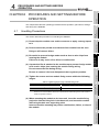
CHAPTER4 PROCEDURES AND SETTINGS BEFORE OPERATION
4 - 1 to 4 - 12
4.1
Handling Precautions •••••••••••••••••••••••••••••••••••••••••••••••••••••••••••••••••••••••••••••••••••••••••••••• 4 - 1
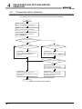
4.2
Procedures before Operation•••••••••••••••••••••••••••••••••••••••••••••••••••••••••••••••••••••••••••••••••••••4 - 2
4.3
Part Names ••••••••••••••••••••••••••••••••••••••••••••••••••••••••••••••••••••••••••••••••••••••••••••••••••••••••••4 - 3
4.4
Wiring •••••••••••••••••••••••••••••••••••••••••••••••••••••••••••••••••••••••••••••••••••••••••••••••••••••••••••••••••4 - 5
4.4.1
4.4.2
4.4.3
4.4.4
4.5
Wiring precautions ••••••••••••••••••••••••••••••••••••••••••••••••••••••••••••••••••••••••••••••••••••••••••••4 - 5
Example of wiring the module and an encoder••••••••••••••••••••••••••••••••••••••••••••••••••••••••••4 - 7
Example of wiring a controller and an external input terminal ••••••••••••••••••••••••••••••••••••••••4 - 8
Example of wiring with an external output terminal •••••••••••••••••••••••••••••••••••••••••••••••••••••4 - 9
Intelligent Function Module Switch Setting •••••••••••••••••••••••••••••••••••••••••••••••••••••••••••••••••• 4 - 10
CHAPTER5 FUNCTIONS
5.1
Pulse Input and Count Methods ••••••••••••••••••••••••••••••••••••••••••••••••••••••••••••••••••••••••••••••••• 5 - 1
5.1.1
5.2
Types of the pulse input method •••••••••••••••••••••••••••••••••••••••••••••••••••••••••••••••••••••••••••5 - 1
Selecting a Counter Format••••••••••••••••••••••••••••••••••••••••••••••••••••••••••••••••••••••••••••••••••••••• 5 - 3
5.2.1
5.2.2
5.3
5 - 1 to 5 - 31
Selecting the linear counter ••••••••••••••••••••••••••••••••••••••••••••••••••••••••••••••••••••••••••••••••• 5 - 4
Selecting the ring counter •••••••••••••••••••••••••••••••••••••••••••••••••••••••••••••••••••••••••••••••••••5 - 5
Using the Counter Value Comparison Function ••••••••••••••••••••••••••••••••••••••••••••••••••••••••••••••5 - 8
5.3.1
5.3.2
5.3.3
5.3.4
Using the coincidence output function •••••••••••••••••••••••••••••••••••••••••••••••••••••••••••••••••••• 5 - 9
Using the continuous comparison function ••••••••••••••••••••••••••••••••••••••••••••••••••••••••••••• 5 - 13
Using the coincidence output test function ••••••••••••••••••••••••••••••••••••••••••••••••••••••••••••• 5 - 22
Coincidence detection interrupt function•••••••••••••••••••••••••••••••••••••••••••••••••••••••••••••••• 5 - 24
5.4
Using the Preset Function••••••••••••••••••••••••••••••••••••••••••••••••••••••••••••••••••••••••••••••••••••••• 5 - 27
5.5
Using the Latch Counter Function ••••••••••••••••••••••••••••••••••••••••••••••••••••••••••••••••••••••••••••• 5 - 29
5.6
Response Delay Time ••••••••••••••••••••••••••••••••••••••••••••••••••••••••••••••••••••••••••••••••••••••••••• 5 - 31
CHAPTER6 UTILITY PACKAGE (GX Configurator-CT)
6 - 1 to 6 - 20
6.1
Utility Package Functions •••••••••••••••••••••••••••••••••••••••••••••••••••••••••••••••••••••••••••••••••••••••••6 - 1
6.2
Installing and Uninstalling the Utility Package•••••••••••••••••••••••••••••••••••••••••••••••••••••••••••••••••6 - 3
6.2.1
6.2.2
6.3
Handling precautions •••••••••••••••••••••••••••••••••••••••••••••••••••••••••••••••••••••••••••••••••••••••••6 - 3
Operating environment••••••••••••••••••••••••••••••••••••••••••••••••••••••••••••••••••••••••••••••••••••••• 6 - 5
Utility Package Operation •••••••••••••••••••••••••••••••••••••••••••••••••••••••••••••••••••••••••••••••••••••••••6 - 7
6.3.1
6.3.2
6.3.3
Common utility package operations •••••••••••••••••••••••••••••••••••••••••••••••••••••••••••••••••••••••6 - 7
Operation overview •••••••••••••••••••••••••••••••••••••••••••••••••••••••••••••••••••••••••••••••••••••••••••6 - 9
Starting the Intelligent function module utility •••••••••••••••••••••••••••••••••••••••••••••••••••••••••• 6 - 11
6.4
Initial Setting ••••••••••••••••••••••••••••••••••••••••••••••••••••••••••••••••••••••••••••••••••••••••••••••••••••••• 6 - 14
6.5
Auto Refresh ••••••••••••••••••••••••••••••••••••••••••••••••••••••••••••••••••••••••••••••••••••••••••••••••••••••• 6 - 16
6.6
Monitoring/Test •••••••••••••••••••••••••••••••••••••••••••••••••••••••••••••••••••••••••••••••••••••••••••••••••••• 6 - 18
6.6.1
Monitoring/test ••••••••••••••••••••••••••••••••••••••••••••••••••••••••••••••••••••••••••••••••••••••••••••••• 6 - 18
CHAPTER7 PROGRAMMING
7.1
7 - 1 to 7 - 18
Programming Procedure ••••••••••••••••••••••••••••••••••••••••••••••••••••••••••••••••••••••••••••••••••••••••••7 - 1
A-7
7.2
For Use in Normal System Configuration ••••••••••••••••••••••••••••••••••••••••••••••••••••••••••••••••••••••7 - 3
7.2.1
Before creating a program•••••••••••••••••••••••••••••••••••••••••••••••••••••••••••••••••••••••••••••••••••7 - 4
7.3
Programming Example when GX Configurator-CT is Used ••••••••••••••••••••••••••••••••••••••••••••••••7 - 6
7.4
Programming Example when GX Configurator-CT is not Used•••••••••••••••••••••••••••••••••••••••••• 7 - 12
7.5
Program Example when the Coincidence Detection Interrupt Function is Used ••••••••••••••••••••• 7 - 17
CHAPTER8 TROUBLESHOOTING
8.1
8 - 1 to 8 - 13
Error Processing and Recovery Methods ••••••••••••••••••••••••••••••••••••••••••••••••••••••••••••••••••••••8 - 1
8.1.1
8.1.2
8.1.3
8.1.4
Checking error description using System Monitor of GX Developer ••••••••••••••••••••••••••••••••8 - 1
When the RUN LED turns OFF•••••••••••••••••••••••••••••••••••••••••••••••••••••••••••••••••••••••••••••8 - 3
When the RUN LED and ERR.LED turn ON •••••••••••••••••••••••••••••••••••••••••••••••••••••••••••••8 - 3
When the RUN LED and FUSE LED turn ON •••••••••••••••••••••••••••••••••••••••••••••••••••••••••••8 - 3
8.2
When the QD64D2 does not Start Counting•••••••••••••••••••••••••••••••••••••••••••••••••••••••••••••••••••8 - 4
8.3
When the QD64D2 does not Normally Count •••••••••••••••••••••••••••••••••••••••••••••••••••••••••••••••••8 - 4
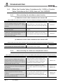
8.4
When the Counter Value Coincidence No.1 (X02) or Counter Value Coincidence No.2 (X05) does not
Turn ON/OFF ••••••••••••••••••••••••••••••••••••••••••••••••••••••••••••••••••••••••••••••••••••••••••••••••••••••••8 - 5
8.4.1
8.4.2
When selecting the coincidence output function ••••••••••••••••••••••••••••••••••••••••••••••••••••••••8 - 5
When selecting the continuous comparison function•••••••••••••••••••••••••••••••••••••••••••••••••••8 - 5
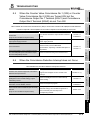
8.5
When the Counter Value Coincidence No.1 (X02) or Counter Value Coincidence No.2 (X05) are Turned
ON, but the Coincidence Output No.1 Terminal (EQU1) and Coincidence Output No.2 Terminal (EQU2)
do not Turn ON ••••••••••••••••••••••••••••••••••••••••••••••••••••••••••••••••••••••••••••••••••••••••••••••••••••••8 - 6
8.6
When the Coincidence Detection Interrupt does not Occur ••••••••••••••••••••••••••••••••••••••••••••••••8 - 6
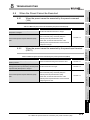
8.7
When the Coincidence Output Test Function Cannot be Executed•••••••••••••••••••••••••••••••••••••••8 - 7
8.8
When the Preset Cannot be Executed••••••••••••••••••••••••••••••••••••••••••••••••••••••••••••••••••••••••••8 - 8
8.8.1
8.8.2
8.9
When the preset cannot be executed by the preset command (Y04)•••••••••••••••••••••••••••••••8 - 8
When the preset cannot be executed by the preset input terminal (PRST)••••••••••••••••••••••••8 - 8
When the Latch Counter Function Cannot be Executed ••••••••••••••••••••••••••••••••••••••••••••••••••••8 - 9
8.9.1
8.9.2
When the latch counter function cannot be executed by the latch counter execution command
(Y07) •••••••••••••••••••••••••••••••••••••••••••••••••••••••••••••••••••••••••••••••••••••••••••••••••••••••••••••8 - 9
When the latch counter function cannot be executed by the latch counter input terminal (LATCH)
••••••••••••••••••••••••••••••••••••••••••••••••••••••••••••••••••••••••••••••••••••••••••••••••••••••••••••••••••••8 - 9
8.10 When the Error Code (Un\G18)/Warning Code (Un\G19) Cannot be Reset ••••••••••••••••••••••••••••8 - 9
8.11 Action and Handling of Errors •••••••••••••••••••••••••••••••••••••••••••••••••••••••••••••••••••••••••••••••••• 8 - 10
8.11.1
8.11.2
Error code list •••••••••••••••••••••••••••••••••••••••••••••••••••••••••••••••••••••••••••••••••••••••••••••••• 8 - 10
Warning code list •••••••••••••••••••••••••••••••••••••••••••••••••••••••••••••••••••••••••••••••••••••••••••• 8 - 13
APPENDICES
App - 1 to App - 2
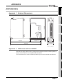
Appendix 1
External Dimensions •••••••••••••••••••••••••••••••••••••••••••••••••••••••••••••••••••••••••••••••••• App - 1
Appendix 2
Difference with the QD62D••••••••••••••••••••••••••••••••••••••••••••••••••••••••••••••••••••••••••• App - 1
INDEX
A-8
Index - 1 to Index - 2
Compliance with the EMC and Low Voltage Directives
(1) For programmable controller system
To configure a system meeting the requirements of the EMC and Low Voltage
Directives when incorporating the Mitsubishi programmable controller (EMC and Low
Voltage Directives compliant) into other machinery or equipment, refer to Chapter 9
"EMC AND LOW VOLTAGE DIRECTIVES" of the QCPU User's Manual (Hardware
Design, Maintenance and Inspection).
The CE mark, indicating compliance with the EMC and Low Voltage Directives, is
printed on the rating plate of the programmable controller.
(2) For the product
For the compliance of this product with the EMC and Low Voltage Directives, refer to
Section 4.4.1 Wiring precautions.
A-9
GENERIC TERMS AND ABBREVIATIONS
This manual describes the type QD64D2 4Mpps capable high-speed counter module
using the following generic terms and abbreviations, unless otherwise specified.
Generic term and
Description
abbreviation
QD64D2
Abbreviation for the type QD64D2 4Mpps capable high-speed counter module
CH
Generic term for CH1 and CH2
Coincidence signal No. m
Generic term for the coincidence signal No. 1 and the coincidence signal No. 2
Coincidence output No. m
Generic term for the coincidence output No. 1 and the coincidence output No. 2
Continuous comparison
Generic term for the continuous comparison No. 1 and the continuous comparison No. 2
No.m
Continuous comparison
Generic term for the continuous comparison No. 1 point 1 to the continuous comparison No. 1 point 16
No.1 point n
Continuous comparison
Generic term for the continuous comparison No. 2 point 1 to the continuous comparison No. 2 point 16
No.2 point n
Continuous comparison
Generic term for the continuous comparison No. 1 point n setting and the continuous comparison No. 2 point
No.m point n setting
n setting
Generic term for the coincidence output No. m point setting and the continuous comparison No. m point n
Comparison point
setting
External coincidence output
Generic term for external coincidence output power supply 12/24V terminal and external coincidence output
power supply terminal
power supply GND (0V) terminal
Personal computer
Generic term for IBM-PC/AT-compatible personal computer
GX Developer
GX Works2
GX Configurator-CT
Product name for MELSEC software packerge
Abbreviation for GX Configurator-CT (SW0D5C-QCTU-E) of counter module setting/monitor tool
Generic term for the Q00JCPU, Q00CPU, Q01CPU, Q02CPU, Q02HCPU, Q06HCPU, Q12HCPU,
Q25HCPU, Q02PHCPU, Q06PHCPU, Q12PHCPU, Q25PHCPU, Q12PRHCPU, Q25PRHCPU, Q00UJCPU,
QCPU (Q mode)
Q00UCPU, Q01UCPU, Q02UCPU, Q03UDCPU, Q04UDHCPU, Q06UDHCPU, Q10UDHCPU,
Q13UDHCPU, Q20UDHCPU, Q26UDHCPU, Q03UDECPU, Q04UDEHCPU, Q06UDEHCPU,
Q10UDEHCPU, Q13UDEHCPU, Q20UDEHCPU, Q26UDEHCPU, Q50UDEHCPU and Q100UDEHCPU
Redundant CPU
Generic term for the Q12PRHCPU and Q25PRHCPU
Generic term for the following:
Windows Vista
Microsoft
Windows Vista
Home Basic Operating System,
Microsoft
Windows Vista
Home Premium Operating System,
Microsoft
Windows Vista
Business Operating System,
Microsoft
Windows Vista
Ultimate Operating System,
Microsoft
Windows Vista
Enterprise Operating System
Generic term for the following:
Windows
XP
Microsoft
Windows
XP Professional Operating System,
Microsoft
Windows
XP Home Edition Operating System
PACKING LIST
The following are included in the package.
Model
Product name
Quantity
QD64D2
Type QD64D2 4Mpps capable high-speed counter module
1
SW0D5C-QCTU-E
GX Configurator-CT Version 1 (single license product) (CD-ROM)
1
SW0D5C-QCTU-EA
GX Configurator-CT Version 1 (volume license product) (CD-ROM)
1
A - 10
OVERVIEW
1
This User's Manual describes the specifications, handling, and programming methods for
the type QD64D2 4Mpps capable high-speed counter module used together with the
MELSEC-Q series CPU module.
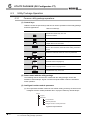
The QD64D2 has the following input methods.
•1 multiple of 1 phase pulse
•2 multiples of 1 phase pulse
•CW/CCW
input
•1 multiple of 2 phases pulse
input
•2 multiples of 2 phases pulse
•4 multiples of 2 phases pulse
input
input
input
SPECIFICATIONS
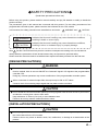
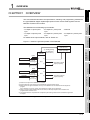
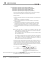
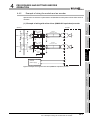
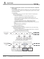
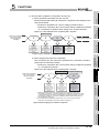
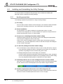
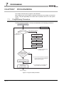
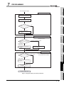
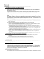
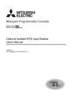
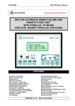
Figure 1.1 shows the general operation of the QD64D2.
Programmable
controller CPU
4
PROCEDURES AND
SETTINGS BEFORE
OPERATION
QCPU (Q mode)
QD64D2
Pulse
Encoder
1)
External
control signal
Controller
4)
CH1
2)
5)
1)
4)
2
3
For details of the input methods, refer to Section 5.1.
3) Reading/writing
I/O signal and
buffer memory
OVERVIEW
OVERVIEW
SYSTEM
CONFIGURATION
CHAPTER1
5
Coincidence signal
output (2 points)
FUNCTIONS
Preset
Latch counter
Pulse
External
control signal
Controller
Preset
Latch counter
CH2
2)
5)
6
Coincidence signal
output (2 points)
UTILITY PACKAGE (GX
Configurator-CT)
Encoder
1) Pulses to be input to the QD64D2 are counted.
2) Preset value and count value can be latched with external control signal.
3) Status of the I/O signal and buffer memory of the QD64D2 can be checked with the sequence
program.
Also, start/stop of a count, preset, and coincidence output can be performed.
4) When a counter value matches with the set value, an interrupt request can be issued to the
programmable controller CPU.
5) The present value is compared with comparison point setting value and the coincidence signal can
be output.
PROGRAMMING
7
Figure 1.1 General operation of the QD64D2
8
TROUBLESHOOTING
1
1-1
1
1.1
OVERVIEW
Features
This section describes the features of the QD64D2.
(1) Counting at the maximum counting speed of 4Mpps is possible. (In 4
multiples of 2 phases)
Since the QD64D2 can be used for high-resolution encoder (e.g. linear scale), the
equipment can improve position detection accuracy and a workpiece can be moved at
high-speed.
(2) Wide range of expression on counting (from -2147483648 to 2147483647)
Count values can be stored in 32-bit signed binary.
(3) Pulse input selection
Pulse input can be selected from 1 multiple of 1 phase, 2 multiples of 1 phase, 1
multiple of 2 phases, 2 multiples of 2 phases, 4 multiples of 2 phases, and CW/CCW.
(4) Counter format selection
Either of the following counter formats can be selected.
(a) Linear counter format
From -2147483648 to 2147483647 can be counted and an overflow can be
detected when the count range is overrun.
(b) Ring counter format
Counts are repeatedly executed between the ring counter upper limit value and
ring counter lower limit value.
(5) Coincidence detection
The QD64D2 can compare the present value and comparison point, notify the
comparison result with input signal, and start an interrupt program when they match.
It also mounts 2-point external coincidence output for each channel, which permits
controlling external devices at high-speed.
According to application, select the coincidence output function or continuous
comparison function.
(a) Coincidence output function
Set 1 as the coincidence detection point for each point to compare it with the
present value.
Reset the coincidence output signal or change the coincidence detection point
with the sequence program.
Controlling equipment according to the operating status, such as change of the
coincidence detection point according to condition, is possible.
1-2
1.1 Features
OVERVIEW
(6) Mounting the coincidence output test function (when using the
continuous comparison function)
By using the coincidence output test function, wiring of the coincidence output
terminals (EQU1, EQU2) and operations can be checked without count operation.
3
SPECIFICATIONS
(7) Preset function
2
SYSTEM
CONFIGURATION
(b) Continuous comparison function
Set from 1 to 16 as the coincidence detection point for each point to compare it
with the present value (Only 1 point can be compared simultaneously).
Whenever a coincidence is detected, the coincidence output signal is reset or the
coincidence detection point is changed automatically.
If this function is used when the coincidence detection point is predetermined, the
sequence program can be reduced, which brings improvement in takt time.
OVERVIEW
1
The present value when the latch counter execution command (Y07) is input or the
latch counter input terminal (LATCH) is turned ON can be latched.
(9) Executing the preset function/latch counter function with external
control signal
Since the QD64D2 is independent of scan time of the programmable controller CPU,
disparity in a span before executing the preset function/latch counter function can be
lessen.
(10)Fuse blown at external output part is detectable.
The QD64D2 can detect fuse blown at external output part and notify it with the blown
fuse detection flag (X1F) and LED display on it.
4
PROCEDURES AND
SETTINGS BEFORE
OPERATION
(8) Latch counter function
5
FUNCTIONS
The present value when the preset command (Y04) is input or the preset input
terminal (PRST) is turned ON can be overwritten to preset value.
The QD64D2 setting can be performed on screen by using GX Configurator-CT sold
separately. Thus, the number of sequence programs results in decreasing and
checking a setting status or operation status of modules easily.
UTILITY PACKAGE (GX
Configurator-CT)
6
(11)Easy setting using GX Configurator-CT
PROGRAMMING
7
8
TROUBLESHOOTING
1
1.1 Features
1-3
2
SYSTEM CONFIGURATION
CHAPTER2
SYSTEM CONFIGURATION
This chapter describes system configurations for the QD64D2.
2.1
Applicable Systems
This section describes the applicable systems.
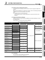
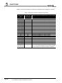
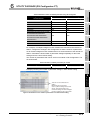
(1) Applicable modules and base units, and No. of modules
(a) When mounted with a CPU module
The table below shows the CPU modules and base units applicable to the
QD64D2 and quantities for each CPU model.
Depending on the combination with other modules or the number of mounted
modules, power supply capacity may be insufficient.
Pay attention to the power supply capacity before mounting modules, and if the
power supply capacity is insufficient, change the combination of the modules.
Table 2.1 Applicable modules and the number of mountable modules
Applicable CPU module
CPU type
Basic model
QCPU*3
High Performance
model QCPU
Process CPU
Programmable
controller CPU
Redundant CPU*4
No. of
CPU model
Q00JCPU
Q00CPU
Q01CPU
Q02CPU
Q02HCPU
Q06HCPU
QCPU
Q02PHCPU
Q06PHCPU
Q12PHCPU
Q25PHCPU
Q12PRHCPU
Q25PRHCPU
Q00UJCPU
Q02UCPU
Q03UDCPU
Up to 24
Up to 64
Up to 64
Up to 53
Up to 8
Up to 24
Up to 36
Q04UDHCPU
Q06UDHCPU
Q10UDHCPU
Q13UDHCPU
Q20UDHCPU
Q26UDHCPU
2-1
Up to 8
Q12HCPU
Q25HCPU
Q00UCPU
Q01UCPU
Universal model
modules*1
2.1 Applicable Systems
Up to 64
Base unit*2
Main base unit
Extension base
unit
2
SYSTEM CONFIGURATION
1
Table 2.1 Applicable modules and the number of mountable modules (Continued)
CPU type
No. of
CPU model
modules*1
Base unit*2
Main base unit
Extension base
OVERVIEW
Applicable CPU module
unit
Q03UDECPU
Q04UDEHCPU
controller CPU
Universal model
QCPU
Q13UDEHCPU
Q20UDEHCPU
Up to 64
SYSTEM
CONFIGURATION
Programmable
2
Q06UDEHCPU
Q10UDEHCPU
Q26UDEHCPU
Q50UDEHCPU
Q100UDEHCPU
Safety CPU
QS001CPU
N/A
3
*5
Up to 64
: Applicable
: N/A
* 1 Limited within the range of I/O points for the CPU module.
* 2 Can be installed to any I/O slot of a base unit.
* 3 For the coincidence detection interrupt function, use the Basic model QCPU of function version B
or later.
* 4 The coincidence detection interrupt function is not supported.
* 5 Connection of extension base units is not available with any safety CPU.
Remark
4
PROCEDURES AND
SETTINGS BEFORE
OPERATION
Q06CCPU-V-B
Q12DCCPU-V
SPECIFICATIONS
Q06CCPU-V
C Controller module
5
FUNCTIONS
For the use of the C Controller module, refer to C Controller Module User's
Manual.
UTILITY PACKAGE (GX
Configurator-CT)
6
PROGRAMMING
7
TROUBLESHOOTING
8
2.1 Applicable Systems
2-2
2
SYSTEM CONFIGURATION
(b) Mounting to a MELSECNET/H remote I/O station
The following table shows network modules that can be mounted to the QD64D2,
the number of mountable network modules, and applicable base units.
The QD64D2 module can be mounted into any I/O slots*1 on the applicable base
unit.
However, the power capacity may be insufficient depending on the combination
with the other mounted modules and the number of mounted modules.
Be sure to check the power capacity when mounting the modules.
T
Table 2.2 Mountable network modules, No. of mountable modules, and mountable base unit
Mountable network
module*3
QJ72LP25-25
QJ72LP25G
QJ72LP25GE
QJ72BR15
Number of
mountable
modules*1
Applicable base unit*2
Main base unit on
Extension base unit
the remote I/O
on the remote I/O
station
station
Up to 64
: Applicable
: N/A
* 1 Limited within the range of I/O points for the network module.
* 2 Can be installed to any I/O slot of a base unit.
* 3 The coincidence detection interrupt function is not supported.
Remark
The Basic model QCPU or C Controller module cannot create the MELSECNET/
H remote I/O network.
2-3
2.1 Applicable Systems
2
SYSTEM CONFIGURATION
1
The QD64D2 of first released version to function version B supports multiple CPU
system.
When using the QD64D2 in a multiple CPU system, refer to the following manual first.
2
QCPU User's Manual (Multiple CPU System)
SYSTEM
CONFIGURATION
(a) Intelligent function module parameters
Write intelligent function module parameters to only the control CPU of the
QD64D2.
Table 2.3 Software package version
Software version
Single CPU system
GX Developer
Version 7 or later
Q02/Q02H/Q06H/
Multiple CPU system
Single CPU system
Version 8 or later
Version 4 or later
Q12H/Q25HCPU
Multiple CPU system
Version 6 or later
Q25PRHCPU
Multiple CPU system
Redundant system
Q00UJ/Q00U/
Single CPU system
Q01UCPU
Multiple CPU system
Q02U/Q03UD/
Single CPU system
Q04UDH/
Q06UDHCPU
Multiple CPU system
Q10UDH/
Single CPU system
Q20UDHCPU
Multiple CPU system
Q13UDH/
Single CPU system
Q26UDHCPU
Multiple CPU system
Q03UDE/Q04UDEH/
Single CPU system
Q06UDEH/Q13UDEH/
Version 8.68W or later
Version 7.10L or later
Use prohibited
Version 8.45X or later
Version 8.76E or later
Version 1.28AE or later
6
Version 8.48A or later
Version 8.76E or later
Version 1.08J or later
Version 8.62Q or later
7
Version 8.68W or later
Q26UDEHCPU
Multiple CPU system
Q10UDEH/
Single CPU system
Q20UDEHCPU
Multiple CPU system
Q50UDEH/
Single CPU system
Q100UDEHCPU
Multiple CPU system
When mounted to the MELSECNET/H remote I/
O station
5
FUNCTIONS
Q12PRH/
Multiple CPU system
Single CPU system
Version 1.08J or later
4
UTILITY PACKAGE (GX
Configurator-CT)
Q12PH/Q25PHCPU
Single CPU system
Version 1.10N or later
Version 8.76E or later
Use prohibited
Use prohibited
Version 1.31H or later
Version 6 or later
Version 1.28AE or later
Use prohibited
(4) Connector
The connector is not included with the QD64D2.
Purchase it with reference to Section 4.3.
2.1 Applicable Systems
PROGRAMMING
Q02H/Q06HCPU
GX Works2
8
TROUBLESHOOTING
Q00J/Q00/Q01CPU
GX Configurator-CT
3
SPECIFICATIONS
Relation between the system using the QD64D2 and software package is shown in
the following table.
GX Developer is necessary when using the QD64D2.
PROCEDURES AND
SETTINGS BEFORE
OPERATION
(3) Supported software packages
Item
OVERVIEW
(2) Support of the multiple CPU system
2-4
2
2.2
SYSTEM CONFIGURATION
About Use of the QD64D2 with Redundant CPU
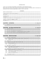
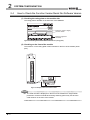
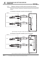
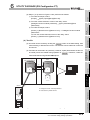
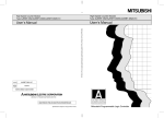
This section explains how to use the QD64D2 with the Redundant CPU.
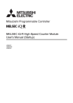
(1) GX Configurator-CT
GX Configurator-CT cannot be used when accessing the Redundant CPU via an
intelligent function module on an extension base unit from GX Developer.
Connect a personal computer with a communication path indicated below.
1
2
Main base unit
Extension base unit
(GX Configurator-CT cannot be used.)
1
Connecting directly to a programmable controller CPU
2
Connecting to a programmable controller CPU via an intelligent function module
(Ethernet module, MELSECNET/H module, or CC-Link module) on the main base unit
Figure 2.1 Communication path which GX Configrator-CT can use
(2) Restrictions when using the Redundant CPUs
The coincidence detection interrupt function is not available.
2-5
2.2 About Use of the QD64D2 with Redundant CPU
1
(1) Number of QD64D2 that can be installed when the remote I/O station is
used
Refer to Section 2.1 concerning the number of the QD64D2 that can be installed
when the remote I/O station is used.
(2) Limitations when using the remote I/O station
2
SYSTEM
CONFIGURATION
This section explains how to use the QD64D2 on the MELSECNET/H remote I/O station.
OVERVIEW
About Use of the QD64D2 on the MELSECNET/H Remote I/O
Station
(b) When the QD64D2 is used on the MELSECNET/H remote I/O station, a delay will
occur due to the link scan time. Therefore, fully verify that there will be no problem
with controllability in the target system.
4
PROCEDURES AND
SETTINGS BEFORE
OPERATION
(Example) When processing is executed using the counter value input by a
sequence program, variations will occur due to a delay in the link scan time.
SPECIFICATIONS
3
(a) The coincidence detection interrupt function cannot be used.
FUNCTIONS
5
UTILITY PACKAGE (GX
Configurator-CT)
6
7
PROGRAMMING
2.3
SYSTEM CONFIGURATION
8
TROUBLESHOOTING
2
2.3 About Use of the QD64D2 on the MELSECNET/H Remote I/O Station
2-6
2
2.4
SYSTEM CONFIGURATION
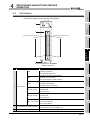
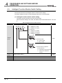
How to Check the Function Version/Serial No./Software Version
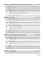
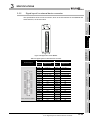
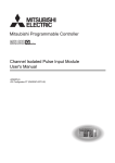
(1) Checking the rating plate on the module side
The rating plate is situated on the side face of the QD64D2.
Serial No. (Upper 6 digits)
function version
100812
Relevant regulation
standards
Figure 2.2 Checking the serial No. and function version (rating plate)
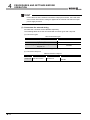
(2) Checking on the front of the module
The serial No. on the rating plate is also indicated on the front of the module (lower
part).
100812000000000-B
Serial number
Figure 2.3 Display on the front of the module
Remark
The serial number is displayed on the front of the module from August 2008
production. Products manufactured during switching period may not have the
serial number on the front of the module.
2-7
2.4 How to Check the Function Version/Serial No./Software Version
SYSTEM CONFIGURATION
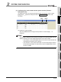
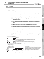
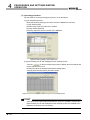
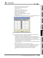
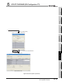
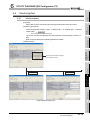
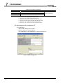
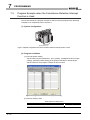
(3) Confirming the serial number on the system monitor (Product
Information List)
To display the screen for checking the serial number and function version, select
[System monitor] and click the Product Inf. List button in GX
Serial
number
2
Function
version
SYSTEM
CONFIGURATION
[Diagnostics]
Developer.
OVERVIEW
1
SPECIFICATIONS
3
Figure 2.4 System monitor
(a) Production number display
Since the QD64D2 does not support the production number display, "-" is
displayed.
POINT
5
FUNCTIONS
The serial No. displayed in the Product Information List of GX Developer may be
different from the one on the rating plate and the front of the module.
• The serial No. on the rating plate and the front of the module indicates the
management information of the product.
• The serial No. in the Product Information List of GX Developer indicates
the functional information on the product, which is updated when a new
function is added.
PROCEDURES AND
SETTINGS BEFORE
OPERATION
4
UTILITY PACKAGE (GX
Configurator-CT)
6
PROGRAMMING
7
8
TROUBLESHOOTING
2
2.4 How to Check the Function Version/Serial No./Software Version
2-8
2
SYSTEM CONFIGURATION
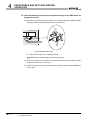
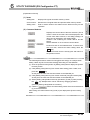
(4) Checking the software version of GX Configurator-CT
The software version of GX Configurator-CT can be checked GX Developer's
"Product information" screen.
[Operating procedure]
GX Developer
[Help]
[Product information]
Software version
(In the case of GX Developer Version 8)
Figure 2.5 [Product information] screen of GX Developer
2-9
2.4 How to Check the Function Version/Serial No./Software Version
3
SPECIFICATIONS
1
SPECIFICATIONS
This chapter describes the performance specifications of the QD64D2, I/O signals to the
programmable controller CPU, specifications of the buffer memory.
For general specifications of the QD64D2, refer to the User's Manual for the CPU module.
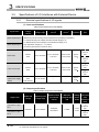
Performance Specifications
The following table shows the performance specifications of the QD64D2.
Table 3.1 Performance specifications of the QD64D2
Item
signal
Signal level ( A,
1-phase input, 2-phase input
B)
Counting speed (max.)
*1 *2
Counting range
SPECIFICATIONS
input
2 channels
Phase
EIA Standard RS-422-A Differential line driver level
(AM26LS31 (manufactured by Texas Instruments Incorporated) or equivalent)
4 multiples of 2 phases : 4Mpps
2 multiples of 1 phase, 2 multiples of 2 phases: 2Mpps
4
1 multiple of 1 phase, 1 multiple of 2 phases, CW/CCW: 1Mpps
32-bit signed binary (-2147483648 to 2147483647)
PROCEDURES AND
SETTINGS BEFORE
OPERATION
Addition method, subtraction method
Type
linear counter format, ring counter format
preset counter function, latch counter function
1
5
Counter
Minimum count pulse
0.5
0.5
FUNCTIONS
width
(Duty ratio 50 %)
6
s)
UTILITY PACKAGE (GX
Configurator-CT)
(Unit: s)
0.25
(Minimum phase difference for 2-phase input: 0.25
For details, refer to Section 3.1.1
Comparison range
Setting value < Count value
Coincide
Comparison result
Interrupt
External
Preset
input
Count value latch
External
Coincidence output
output
Setting value = Count value
Setting value > Count value
detection
7
With coincidence detection interrupt function
24VDC 2 to 5mA
PROGRAMMING
nce
32-bit signed binary
Transistor (sinking type) output: 2 points/channel
12/24VDC 0.5 A/point 2 A/common
Derating
Applied (refer to Section 3.1.2 )
Number of occupied I/O points
32 points (I/O assignment: Intelligent 32 points)
5VDC internal current consumption
0.53 A
Weight
0.16 kg
8
* 1 Note that counting a pulse whose phase difference between phase A and phase B is small may
result in a count error.
For the relation of phase difference between phase A and phase B, refer to Section 3.3.1.
* 2 The maximum counting speed is determined in the pulse input mode.
Counting speed cannot be changed.
3.1 Performance Specifications
3-1
TROUBLESHOOTING
Count
3
Specifications
Number of channels
2
SYSTEM
CONFIGURATION
3.1
OVERVIEW
CHAPTER3
3
SPECIFICATIONS
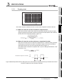
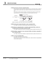
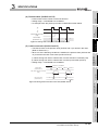
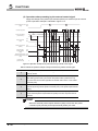
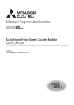
3.1.1
Relation of phase difference between phase A and phase B
The relation indicated below is for each pulse input mode at the maximum counting speed.
Pulse input waveform that does not reach to the maximum counting speed is also
applicable.
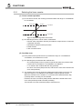
(a) At 1-phase input
Pulse input waveform at 1-phase input input needs to satisfy the following
conditions (duty ratio of 50%).
t (=tH+tL) = 1.0 s
tH, tL = 0.5 s (= 0.5
Differential
voltage
H level
t)
t
0.1V
L level
0.1V
-0.1V
tH
tL
Figure 3.1 Pulse input waveform at 1-phase input
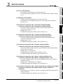
(b) At 2-phase input
Pulse input waveform at 2-phase input needs to satisfy both the condition at 1phase input and the condition below.
t1, t2, t3, t4 = 0.25 s (= 0.25 t)
Differential
voltage
H level
A
L level
Differential
voltage
H level
0.1V
-0.1V
t1
t2
0.1V
B
0.1V
0.1V
-0.1V
L level
Figure 3.2 Pulse input waveform at 2-phase input 1
Differential
voltage
H level
A
L level
Differential
voltage
H level
B
0.1V
-0.1V
t3
-0.1V
t4
0.1V
-0.1V
0.1V
L level
Figure 3.3 Pulse input waveform at 2-phase input 2
3-2
3.1 Performance Specifications
3.1.1 Relation of phase difference between phase A and phase B
SPECIFICATIONS
1
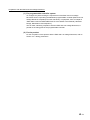
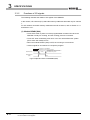
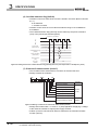
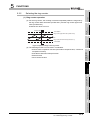
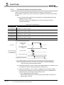
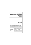
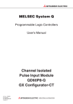
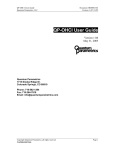
3.1.2
Derating chart
OVERVIEW
3
100
2
80
70
SYSTEM
CONFIGURATION
ON ratio (%)
90
60
50
40
0
10
20
30
40
50
55
Ambient temperature( )
3
Figure 3.4 Derating chart
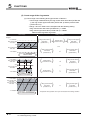
(1) When all channels are the coincidence output function
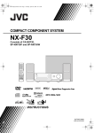
(2) When all channels are the continuous comparison function
Take care so that the ratio of continuous comparison No. m ON time setting (Un\G52,
Un\G102) (t1) to the time from start of coincidence output to the next coincidence
output (t2) in Figure 3.5 may not exceed the ON ratio in Figure 3.4.
(For interval of the continuous comparison No. m point n setting that decides t2, refer
to Section 5.3.2.)
Coincidence output No. m terminal
t2[ms]
100 [%]
6
UTILITY PACKAGE (GX
Configurator-CT)
t1[ms]
ON ratio [%]
ON
OFF
t1
5
FUNCTIONS
100 [%]
t1
7
t2
Figure 3.5 Relationship between ON time setting in the case of the continuous comparison function (t1) and the time from start of
coincidence output to the next coincidence output (t2)
PROGRAMMING
ON ratio [%]
The number of points that
external coincidence output
(ON) is executed
4 (point)
4
PROCEDURES AND
SETTINGS BEFORE
OPERATION
Take care so that the ratio of the number of points that external coincidence output
(ON) is executed to the number of external coincidence output points of the module (4
points) does not exceed the ON ratio in Figure 3.4.
SPECIFICATIONS
This section explains conditions for each counter value comparison function selection.
TROUBLESHOOTING
8
3.1 Performance Specifications
3.1.2 Derating chart
3-3
3
SPECIFICATIONS
(3) When (CH1 or CH2) is the coincidence output function and (CH2 or CH1)
is the continuous comparison function
Take care so that the addition of the ratio of above (1) "When all channels are the
coincidence output function" in the CH where the coincidence output function is set
and a value when the ratio of above (2) "When all channels are the continuous
comparison function" in the CH where the continuous comparison function is set is
divided by 2 may not exceed the ON ratio in Figure 3.4
Ratio of above (1) "When all channels are the
coincidence output function" [%]
ON ratio [%]
(
3-4
The number of points that external
coincidence output (ON) is executed
4 (point)
3.1 Performance Specifications
3.1.2 Derating chart
(
100 [%]
Ratio of above (2) "When all channels are the
continuous comparison function" [%]
+
+
2
(
(
t1[ms]
100 [%]
t2[ms]
2
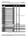
SPECIFICATIONS
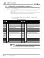
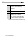
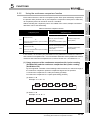
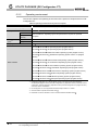
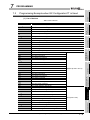
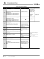
Table 3.2 Function list of the QD64D2
Function *1
Description
Counts within the range from -2147483648 to 2147483647.
Linear counter function
An overflow occurs when a count exceeds the count range.
Repeats a count between the ring counter upper limit value
Ring counter function
Coincidence output
function
Counter
value
Reference
and the lower limit value.
Compares preset coincidence detection point of an arbitrary
channel with the present counter value and outputs the
Section 5.2.1
Section 5.2.2
Section 5.3.1
counter value coincidence.
Compares any of preset coincidence detection points of an
Continuous comparison
arbitrary channel with the present counter value and
function
outputs the counter value coincidence during the set time
Section 5.3.2
2
SYSTEM
CONFIGURATION
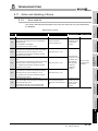
The following table shows the functions of the QD64D2.
I/O numbers (X/Y) and buffer memory addresses in Description describe only for channel
1.
For I/O numbers (X/Y) of channel 2 and buffer memory addresses, refer to Section 3.3.1.
OVERVIEW
Function List
3
SPECIFICATIONS
3.2
1
4
after the coincidence.
comparison
Coincidence output
function
test function
Coincidence detection
interrupt function
Checks wiring of coincidence output.
This function can be used only when the continuous
Section 5.3.3
comparison function is selected.
Generates an interrupt signal to the programmable
controller CPU when a coincidence is detected, and starts
Section 5.3.4
Section 5.4
Latch counter function
Latches the present value.
Section 5.5
5
FUNCTIONS
Preset function
an interrupt program.
Overwrites present value to an arbitrary value.
PROCEDURES AND
SETTINGS BEFORE
OPERATION
3
* 1 The functions can be used in combination.
However, as for the following functions, select either of them.
• Linear counter function, ring counter function
• Coincidence output function, continuous comparison function
UTILITY PACKAGE (GX
Configurator-CT)
6
PROGRAMMING
7
TROUBLESHOOTING
8
3.2 Function List
3-5
3
SPECIFICATIONS
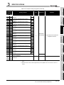
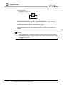
3.3
I/O Signals to the Programmable Controller CPU
3.3.1
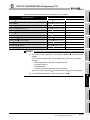
List of I/O signals
The following table shows the I/O signals from the QD64D2 to the programmable
controller CPU.
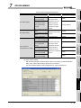
Note that I/O numbers (X/Y) mentioned in this and the subsequent chapters are assumed
when the QD64D2 is mounted to the null I/O slot on the main base unit.
(1) List of input signals (Signal direction: QD64D2
controller CPU)
Programmable
Table 3.3 List of input signals
I/O
Signal name
number
X00
Module READY
I/O
Signal name
number
X10
Reserved
X01
Counter value large No.1
X11
Counter value large No.1
X02
Counter value coincidence No.1
X12
Counter value coincidence No.1
X03
Counter value small No.1
X13
Counter value small No.1
X04
Counter value large No.2
X14
Counter value large No.2
X05
Counter value coincidence No.2
X15
Counter value coincidence No.2
X06
Counter value small No.2
X16
Counter value small No.2
X07
Reserved
X17
Reserved
External preset request detection
X18
X08
X09
X0A
CH1
During continuous comparison No.1
execution *1
During continuous comparison No.2
execution
*1
X19
X1A
CH2
External preset request detection
During continuous comparison No.1
execution *1
During continuous comparison No.2
execution *1
X0B
Reserved
X1B
Reserved
X0C
Reserved
X1C
Reserved
X0D
Error occurrence
X1D
Error occurrence
X0E
Warning occurrence
X1E
Warning occurrence
X0F
Reserved
X1F
Blown fuse detection flag
* 1 The signals are used only for the continuous comparison function.
POINT
The reserved signals above are for system use, not for users. If used (turning ON/
OFF) by a user, the functions of the QD64D2 are not guaranteed.
3-6
3.3 I/O Signals to the Programmable Controller CPU
3.3.1 List of I/O signals
SPECIFICATIONS
(2) List of output signals (Signal direction: Programmable controller CPU
QD64D2)
Table 3.4 List of output signals
Y10
Coincidence signal No.1 reset
Y01
Y11
command *1
Coincidence signal No.2 reset
Y02
Y12
command *1
Coincidence output enable
Y03
Y13
command *1
Reserved
command *1
command *1
Preset command
Y05
Subtraction count command
Y15
Subtraction count command
Y06
Count enable command
Y16
Count enable command
Y08
Y09
Y0A
Y0B
Y0C
Y0D
Y17
command
External preset request
Y18
detection reset command
Continuous comparison No.1
Y19
execution command *2
Continuous comparison No.2
Y1A
execution command *2
Coincidence output No.1 test
command
Y1B
*2
Coincidence output No.2 test
command
Y1C
*2
Error reset command
Y1D
Y0E
3
Coincidence output enable
Y14
Latch counter execution
4
Latch counter execution
CH2 command
External preset request
detection reset command
Continuous comparison No.1
execution command *2
5
Continuous comparison No.2
execution command *2
Coincidence output No.1 test
command *2
Coincidence output No.2 test
command *2
6
Error reset command
Y1E
Reserved
---
Y0F
2
---
command *1
Coincidence signal No.2 reset
Preset command
CH1
timing
Coincidence signal No.1 reset
Y04
Y07
Operation
SYSTEM
CONFIGURATION
---
Signal name
SPECIFICATIONS
number
PROCEDURES AND
SETTINGS BEFORE
OPERATION
Reserved
I/O
timing
Reserved
---
Y1F
* 1 The signal is only used for the coincidence output function.
* 2 The signal is only used for the continuous comparison function.
7
POINT
(1) The reserved signals above are for system use, not for users. If used (turning
ON/OFF) by a user, the functions of the QD64D2 are not guaranteed.
(2) Definitions of the expression in Operation timing are as follows.
•
:Enabled while the signal is ON.
ON time should be 2ms or longer.
•
:Enabled when the signal is turned from OFF to ON.
ON time and OFF time should be 2ms or longer.
3.3 I/O Signals to the Programmable Controller CPU
3.3.1 List of I/O signals
8
TROUBLESHOOTING
Y00
Operation
FUNCTIONS
Signal name
UTILITY PACKAGE (GX
Configurator-CT)
I/O
number
OVERVIEW
1
PROGRAMMING
3
3-7
3
SPECIFICATIONS
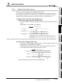
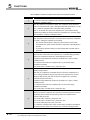
3.3.2
Functions of I/O signals
The following indicates the details of I/O signals of the QD64D2.
In this section, I/O numbers (X/Y) and buffer memory addresses are listed only for channel
1.
For I/O numbers and buffer memory addresses used for channel 2, refer to Section 3.3.1
and Section 3.4.1.
(1) Module READY(X00)
• Turns ON at reset or power-on of the programmable controller CPU when the
QD64D2 is ready for counting, and the counting process is executed.
• Turns OFF when a watchdog timer error or an error which affects the system
(Error code: 810 to 860) occurs.
• When the module READY (X00) is OFF, the counting is not executed.
• Use this signal for an interlock of a sequence program.
Operation by the QD64D2
Operation by the sequence program
QD64D2 status
In
preparation
Ready
Watchdog timer error or an error
that affects the system
ON
Module READY
(X00)
OFF
Figure 3.6 Operation of the module READY (X00)
3-8
3.3 I/O Signals to the Programmable Controller CPU
3.3.2 Functions of I/O signals
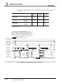
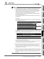
SPECIFICATIONS
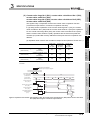
(a) Operation when used for the coincidence output function (Refer to Section 5.3.1.)
Counter value
large
No.1(X01)
Counter value
coincidence
No.1(X02)
Counter value
small
No.1(X03)
Present value
(Un\G12 and 13)
<
Coincidence output No.1 point
setting
(Un\G6 and 7)
OFF
OFF
ON
Present value
(Un\G12 and 13)
=
Coincidence output No.1 point
setting
(Un\G6 and 7)
OFF
ON*
OFF
Present value
(Un\G12 and 13)
>
Coincidence output No.1 point
setting
(Un\G6 and 7)
ON
OFF
OFF
PROCEDURES AND
SETTINGS BEFORE
OPERATION
5
FUNCTIONS
Operation by the QD64D2
Operation by the sequence program
Immediately after power-on or reset
of the programmable controller CPU
0
0
98
1
99
100
101
102
ON
ON
Counter value large
No.1 (X01)
6
100
UTILITY PACKAGE (GX
Configurator-CT)
Present value
(Un\G12 and 13)
OFF
ON
Counter value coincidence
No.1 (X02)
OFF
OFF
7
OFF
ON
ON
Coincidence signal No.1
reset command
(Y01)
OFF
ON
Counter value small
No.1 (X03)
3
4
* The counter value coincidence No.1 (X02) remains ON until the coincidence signal No.1 reset command (Y01) is
turned ON.
Coincidence output
No.1 point setting
(Un\G6 and 7)
2
SYSTEM
CONFIGURATION
The signals notify a comparison result in the counter value comparison function
(coincidence output function, continuous comparison function).
In (a) and (b) below, operations of the counter value large No.1 (X01), the counter
value coincidence No.1 (X02) and the counter value small No.1 (X03) are explained.
For the counter value large No.2 (X04), the counter value coincidence No.2 (X05),
and the counter value small No.2 (X06), operations are the same except that I/O
numbers (X/Y) and buffer memory addresses of the point used for comparison are
different.
SPECIFICATIONS
(2) Counter value large No.1 (X01), counter value coincidence No.1 (X02),
counter value small No.1 (X03)
counter value large No.2 (X04), counter value coincidence No.2 (X05),
counter value small No.2 (X06)
OVERVIEW
1
OFF
t*
OFF
t*
* t 2ms
Figure 3.7 Operation of the counter value large No.1 (X01), the counter value coincidence No.1 (X02) and the counter value small
No.1 (X03) when using the coincidence output function
PROGRAMMING
3
TROUBLESHOOTING
8
3.3 I/O Signals to the Programmable Controller CPU
3.3.2 Functions of I/O signals
3-9
3
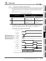
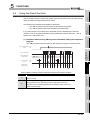
SPECIFICATIONS
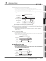
(b) Operation when used for the continuous comparison function (Refer to Section
5.3.2.)
Counter value
large
No.1(X01)
Counter value
coincidence
No.1(X02)
Counter value
small
No.1(X03)
Present value
(Un\G12 and 13)
<
Continuous comparison No.1 point
n setting
(Un\G54 to 85)
OFF
OFF
ON
Present value
(Un\G12 and 13)
=
Continuous comparison No.1 point
n setting
(Un\G54 to 85)
OFF
ON*
OFF
Present value
(Un\G12 and 13)
>
Continuous comparison No.1 point
n setting
(Un\G54 to 85)
ON
OFF
OFF
* The counter value coincidence No.1 (X02) remains ON for the preset time of the continuous comparison No.1
ON time setting (Un\G52).
Usage condition of the following operation diagram
Continuous comparison No.1 start point setting (Un\G50): 1 (point 1)
Continuous comparison No.1 repeat point setting (Un\G51): 3 (point 3)
Continuous comparison No.1 point 1 setting (Un\G54 and 55): 100
Continuous comparison No.1 point 2 setting (Un\G56 and 57): 10000
Continuous comparison No.1 point 3 setting (Un\G58 and 59): 20000
Operation by the QD64D2
Operation by the sequence program
Continuous comparison
No.1 execution command
OFF
(Y09)
During continuous
comparison No.1
execution (X09)
ON
OFF
Continuous comparison
No.1 point monitor
during comparison
(Un\G86)
Present value
(Un\G12 and 13)
ON
0
0
1
1
2
2
98 99 100 101 102
9998 9999 10000 10001 10002
ON
Counter value
large No.1 (X01)
ON
Counter value
coincidence No.1
(X02)
ON
ON
OFF
OFF
ON
OFF
ON
t2*2
OFF
OFF
ON
OFF
ON
OFF
19998 19999 20000 20001 20002
ON
t1*1
ON
1
ON
OFF
Coincidence output
No.1 terminal
(EQU1)
Counter value
small No.1 (X03)
3
OFF
ON
OFF
OFF
*1 t1 = Continuous comparison No.1 ON time setting (Un\G52)
*2 t1 < t2 < (t1+1ms)
Figure 3.8 Operation of the counter value large No.1 (X01), the counter value coincidence No.1 (X02) and the counter value small
No.1 (X03) when using the continuous comparison function
3 - 10
3.3 I/O Signals to the Programmable Controller CPU
3.3.2 Functions of I/O signals
SPECIFICATIONS
1
Operation by the QD64D2
Operation by the sequence program
Preset value setting
(Un\G4 and 5)
100
ON
Preset input terminal
(PRST)
OFF
3
ON
External preset request detection
(X08)
OFF
ON
SPECIFICATIONS
OFF
t*
100
*t 2ms
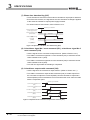
Figure 3.9 Operation of the external preset request detection (X08)
4
(4) During continuous comparison No.1 execution (X09), during continuous
comparison No.2 execution (X0A)
• Turns ON during execution of the continuous comparison function. (Refer to
Section 5.3.2.)
(5) Error occurrence (X0D)
• Turns ON when an error occurs.
• To turn OFF the error occurrence (X0D), fix the cause of the error and then turn
ON the error reset command (Y0D).
Operation by the QD64D2
Operation by the sequence program
ON
0
100
6
OFF
t*
0
ON
Error occurrence
(X0D)
OFF
* t 2ms
Figure 3.10 Operation of the error occurrence (X0D)
(6) Warning occurrence (X0E)
• Turns ON when a warning occurs.
• To turn OFF the warning occurrence (X0E), fix the cause of the warning and then
turn ON the error reset command (Y0D).
Operation by the QD64D2
Operation by the sequence program
ON
Error reset command
(Y0D)
Warning code
(Un\G19)
t*
0
31
7
8
OFF
0
ON
Warning occurrence
(X0E)
5
UTILITY PACKAGE (GX
Configurator-CT)
Error reset command
(Y0D)
PROCEDURES AND
SETTINGS BEFORE
OPERATION
0
FUNCTIONS
Present value
(Un\G12 and 13)
PROGRAMMING
External preset request
detection reset command
(Y08)
Error code
(Un\G18)
2
SYSTEM
CONFIGURATION
• Turns ON when the preset input terminal (PRST) is turned ON.
• To turn OFF the external preset request detection (X08), turn ON the external
preset request detection reset command (Y08).
• The preset cannot be executed while the external preset request detection (X08)
is ON.
OVERVIEW
(3) External preset request detection (X08)
TROUBLESHOOTING
3
OFF
* t 2ms
Figure 3.11 Operation of the warning occurrence (X0E)
3.3 I/O Signals to the Programmable Controller CPU
3.3.2 Functions of I/O signals
3 - 11
3
SPECIFICATIONS
(7) Blown fuse detection flag (X1F)
• Turns ON when a fuse blown of the external coincidence output part is detected.
• Even if the fuse is blown, the signal does not turn ON unless a voltage is applied
to the external coincidence output power supply terminal.
• For actions when a fuse is blown, refer to Section 8.1.4.
.
Operation by the QD64D2
ON
External coincidence output
power supply terminal
External coincidence output
part fuse status
OFF
Normal
Fuse blown
ON
Blown fuse detection flag
(X1F)
Error code
(Un\G18)
OFF
860
0
Error occurrence
(X0D)
ON
Figure 3.12 Operation of the blown fuse detection flag (X1F)
(8) Coincidence signal No.1 reset command (Y01), coincidence signal No.2
reset command (Y02)
• Use the signals for the coincidence output function. (Refer to Section 5.3.1.)
• Turn ON the coincidence signal No.1 reset command (Y01) to reset the counter
value coincidence No.1 (X02).
• Turn ON the coincidence signal No.2 reset command (Y02) to reset the counter
value coincidence No.2 (X05).
• Turn OFF the signal after the resetting is completed.
(9) Coincidence output enable command (Y03)
• Use the signal for the coincidence output function. (Refer to Section 5.3.1.)
• Turn ON the coincidence output enable command (Y03) to enable output from
the coincidence output No.1 terminal (EQU1) and the coincidence output No.2
terminal (EQU2) of the external device connector when the count value coincides
with the comparison point.
Operation by the QD64D2
Counter value coincidence No.1
(X02)
ON
ON
Counter value coincidence No.2
(X05)
Coincidence output enable command
(Y03)
Coincidence output No.1 terminal
(EQU1)
ON
OFF
ON
OFF
ON
Coincidence output No.2 terminal
(EQU2)
OFF
Figure 3.13 Operation of the coincidence output enable command (Y03)
3 - 12
3.3 I/O Signals to the Programmable Controller CPU
3.3.2 Functions of I/O signals
3
SPECIFICATIONS
1
• Check that the present value (Un\G12 and 13) has been changed, then turn OFF
the preset command (Y04).
• While the external preset request detection (X08) is ON, the preset cannot be
executed by the preset command (Y04).
Operation by the QD64D2
Preset value setting
(Un\G4 and 5)
100
3
ON
Preset command
(Y04)
OFF
100
* t 2ms
Figure 3.14 Operation of the preset command (Y04)
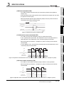
• Turn ON to execute the subtraction count at 1-phase input mode.
• In the 1-phase pulse input mode, the subtraction count is executed when the
phase B pulse or the subtraction count command (Y05) is turned ON.
• When the pulse input mode is 1 multiple of 1 phase, counting is executed as
shown below.
• For the addition count, check that the phase B pulse and the subtraction count
command (Y05) are turned OFF.
ON
ON
B
OFF
ON
6
Subtraction count command
(Y05)
Present value
(Un\G12 and 13)
99
100
99
98
97
Figure 3.15 Operation of the subtraction count command (Y05) (when the pulse input mode is 1 multiple of 1 phase)
(12)Count enable command (Y06)
7
• Turn ON the count enable command (Y06) to start the count operation.
• When the pulse input mode is 1 multiple of 1 phase, counting is executed as
shown below.
A
B
8
ON
0
1
TROUBLESHOOTING
Count enable command
(Y06)
Present value
(Un\G12 and 13)
5
FUNCTIONS
A
PROCEDURES AND
SETTINGS BEFORE
OPERATION
4
(11)Subtraction count command (Y05)
UTILITY PACKAGE (GX
Configurator-CT)
0
SPECIFICATIONS
t*
PROGRAMMING
Present value
(Un\G12 and 13)
2
SYSTEM
CONFIGURATION
• Turn ON the preset command (Y04) to execute the preset function (Refer to
Section 5.4).
OVERVIEW
(10)Preset command (Y04)
2
Figure 3.16 Operation of the count enable command (Y06) (when the pulse input mode is 1 multiple of 1 phase)
3.3 I/O Signals to the Programmable Controller CPU
3.3.2 Functions of I/O signals
3 - 13
3
SPECIFICATIONS
(13)Latch counter execution command (Y07)
• When the latch counter execution command (Y07) is turned from OFF to ON, the
present value (Un\G12 and 13) is stored in the latch count value (Un\G14 and
15).
• Turn OFF the latch counter execution command (Y07) after the present value
(Un\G12 and 13) is stored in the latch count value (Un\G14 and 15).
Operation by the QD64D2
Present value
(Un\G12 and 13)
0
1
2
ON
Latch counter execution command
(Y07)
Latch count value
(Un\G14 and 15)
3
4
ON
OFF
t*
0
OFF
t*
1
3
* t 2ms
Figure 3.17 Operation of the latch counter execution command (Y07)
(14)External preset request detection reset command (Y08)
• Turn ON to turn OFF the external preset request detection (X08).
(15)Continuous comparison No.1 execution command (Y09), continuous
comparison No.2 execution command (Y0A)
• Turn ON to execute the continuous comparison function. (Refer to Section 5.3.2.)
(16)Coincidence output No.1 test command (Y0B), coincidence output No.2
test command (Y0C)
• Turn ON to execute the coincidence output test function. (Refer to Section 5.3.3.)
(17)Error reset command (Y0D)
• Turn ON to reset the error and warning.
• After fixing the cause of the error, reset the error code so that the newly detected
errors can be checked.
3 - 14
3.3 I/O Signals to the Programmable Controller CPU
3.3.2 Functions of I/O signals
3.4
SPECIFICATIONS
1
Buffer Memory Assignment
3.4.1
OVERVIEW
3
List of buffer memory assignment
The following table shows the buffer memory assignment of the QD64D2. For details of
each buffer memory, refer to Section 3.4.2.
2
Initial
value
*1
(L)
(H)
(L)
Ring counter upper limit value *2
(H)
(L)
Preset value setting *2
(H)
(L)
Coincidence output No.1 point setting *2
(H)
(L)
Coincidence output No.2 point setting *2
(H)
Coincidence output No.1 point change request
Coincidence output No.2 point change request
(L)
Present value *2
(H)
(L)
Latch count value *2
(H)
Read/
write
Remarks
3
Ring counter lower limit value *2
Overflow detection flag
17
18
19
20
to
49
50
217
218
219
220
to
249
250
External I/O status monitor
Error code
Warning code
51
251
52
53
54
252
253
254
55
255
56
256
SPECIFICATIONS
Only used for the coincidence output
PROCEDURES AND
SETTINGS BEFORE
OPERATION
function.
4
0
----
5
Only used for the linear counter
function.
----
----
Continuous comparison No.1 start point setting
Continuous comparison No.1 repeat point
setting
Continuous comparison No.1 ON time setting
Reserved
Continuous comparison No.1 point 1
(L)
*2
enabled.
Read only
Reserved
setting *2
Continuous comparison No.1 point 2
----
are
FUNCTIONS
216
Read/write
Read/write
0
57
257
258
setting
Continuous comparison No.1 point 3
(H)
58
59
259
setting *2
(H)
(L)
are
enabled.
----
(H)
(L)
----
----
Read/write
0
are
enabled.
6
----
Only used for the continuous
comparison function.
----
7
Only used for the continuous
comparison function.
* 1 Initial value which is set when the module is powered on or the programmable controller CPU is
reset.
* 2 Read and write a value in 32-bit signed binary format. (Make sure to use a value in units of 2
words.)
3.4 Buffer Memory Assignment
3.4.1 List of buffer memory assignment
UTILITY PACKAGE (GX
Configurator-CT)
16
Only used for the ring counter function.
3 - 15
PROGRAMMING
notation)
CH1 CH2
0
200
1
201
2
202
3
203
4
204
5
205
6
206
7
207
8
208
9
209
10
210
11
211
12
212
13
213
14
214
15
215
Setting contents
8
TROUBLESHOOTING
(decimal
SYSTEM
CONFIGURATION
Table 3.5 List of buffer memory assignment
Address
3
SPECIFICATIONS
Table 3.5 List of buffer memory assignment (Continued)
Address
Initial
(decimal
Setting contents
notation)
CH1 CH2
60
260 Continuous comparison No.1 point 4
61
261
62
262
63
263
64
264
65
265
66
266
67
267
68
268
69
269
70
270
71
271
72
272
73
273
74
274
75
275
76
276
77
277
78
278
79
279
80
280
81
281
82
282
83
283
84
284
85
285
86
286
87
287
to
99
100
101
102
103
104
to
299
300
301
302
303
304
105
305
106
306
107
307
*2
setting
Continuous comparison No.1 point 5
value
(H)
(L)
(H)
*2
(H)
setting
Continuous comparison No.1 point 7
*2
(L)
(L)
setting
Continuous comparison No.1 point 8
(H)
setting *2
Continuous comparison No.1 point 9
(H)
*2
setting
Continuous comparison No.1 point 10
*2
(L)
(L)
(H)
(L)
setting
Continuous comparison No.1 point 11
(H)
setting *2
Continuous comparison No.1 point 12
(H)
*2
setting
Continuous comparison No.1 point 13
*2
(L)
0
are enabled.
Only used for the continuous
comparison function.
(L)
(L)
(H)
setting *2
Continuous comparison No.1 point 15
(H)
setting
Continuous comparison No.1 point 16
Read/write
(H)
setting
Continuous comparison No.1 point 14
*2
Remarks
(L)
*2
setting
Continuous comparison No.1 point 6
Read/write
*1
(L)
(L)
(H)
(L)
*2
(H)
setting
Continuous comparison No.1 point monitor
Read only
during comparison
Reserved
----
Continuous comparison No.2 start point setting
Continuous comparison No.2 repeat point setting
Continuous comparison No.2 ON time setting
Reserved
(L)
Continuous comparison No.2 point 1
setting *2
Continuous comparison No.2 point 2
setting
*2
(H)
(L)
0
----
0
----
----
Read/write
Only used for the continuous
are enabled.
comparison function.
----
----
Read/write
Only used for the continuous
are enabled.
comparison function.
(H)
* 1 Initial value which is set when the module is powered on or the programmable controller CPU is
reset.
* 2 Read and write a value in 32-bit signed binary format. (Make sure to use a value in units of 2
words.)
3 - 16
3.4 Buffer Memory Assignment
3.4.1 List of buffer memory assignment
3
SPECIFICATIONS
1
Table 3.5 List of buffer memory assignment (Continued)
Address
Initial
112
113
114
115
116
117
118
119
120
121
122
123
124
125
126
127
128
129
130
131
132
133
134
135
312
313
314
315
316
317
318
319
320
321
322
323
324
325
326
327
328
329
330
331
332
333
334
335
136
336
137
to
199
337
to
399
setting
Continuous comparison No.2 point 5
setting *2
Continuous comparison No.2 point 6
setting *2
Continuous comparison No.2 point 7
setting *2
Continuous comparison No.2 point 8
setting *2
Continuous comparison No.2 point 9
setting *2
Continuous comparison No.2 point 10
setting *2
Continuous comparison No.2 point 11
setting *2
Continuous comparison No.2 point 12
setting *2
Continuous comparison No.2 point 13
setting *2
Continuous comparison No.2 point 14
setting *2
Continuous comparison No.2 point 15
setting *2
Continuous comparison No.2 point 16
setting *2
Continuous comparison No.2 point monitor
SYSTEM
CONFIGURATION
311
(L)
(H)
(L)
(H)
(L)
(H)
(L)
(H)
(L)
(H)
(L)
(H)
(L)
(H)
(L)
(H)
(L)
(H)
(L)
(H)
(L)
(H)
(L)
(H)
(L)
(H)
3
Read/write
0
are enabled.
Only used for the continuous
comparison function.
4
5
6
Read only
during comparison
Reserved
SPECIFICATIONS
111
*2
2
(H)
PROCEDURES AND
SETTINGS BEFORE
OPERATION
310
(L)
FUNCTIONS
110
setting
Continuous comparison No.2 point 4
Remarks
----
----
----
* 1 Initial value which is set when the module is powered on or the programmable controller CPU is
reset.
* 2 Read and write a value in 32-bit signed binary format. (Make sure to use a value in units of 2
words.)
7
PROGRAMMING
309
Read/write
*1
8
TROUBLESHOOTING
109
*2
value
UTILITY PACKAGE (GX
Configurator-CT)
Setting contents
notation)
CH1 CH2
108 308 Continuous comparison No.2 point 3
OVERVIEW
(decimal
3.4 Buffer Memory Assignment
3.4.1 List of buffer memory assignment
3 - 17
3
SPECIFICATIONS
POINT
• The reserved areas in the above table and areas not mentioned in the
table are for system use, not for users. If written by a user, the functions
of the QD64D2 are not guaranteed.
• All data in the buffer memory of the QD64D2 are initialized when the
module is powered on or the programmable controller CPU is reset. To
save the necessary data, use the FROM/DFRO/TO/DTO instructions in
the sequence program or make setting with the utility package for writing/
reading of the buffer memory data.
• Since the buffer memory contents are automatically updated by count
operation, the latest count value can be read from the buffer memory.
3 - 18
3.4 Buffer Memory Assignment
3.4.1 List of buffer memory assignment
SPECIFICATIONS
1
Details of the buffer memory
This section describes details of the QD64D2 buffer memory.
In this section, I/O numbers (X/Y) and buffer memory addresses are listed for channel 1
and coincidence output No.1. For I/O numbers and buffer memory addresses used for
channel 2 and coincidence output No.2, refer to Section 3.3.1 and Section 3.4.1.
(1) Ring counter lower limit value (Un\G0 and 1)
Ring counter upper limit value (Un\G2 and 3)
• This area is used for setting a count range for the ring counter. (Refer to Section
5.2.2.)
• Setting range: -2147483648 to 2147483647
OVERVIEW
3.4.2
2
SYSTEM
CONFIGURATION
3
3
Operation by the QD64D2
SPECIFICATIONS
ON
Count enable command
(Y06)
*1
100
200 *2
*1
Ring counter upper limit value
(Un\G2 and 3)
0
100
4
200 *2
*1 Setting value of the ring counter upper limit value (Un\G2 and 3) and the ring counter lower
limit value (Un\G0 and 1) becomes effective when the count enable command (Y06) is turned
from OFF to ON.
*2 It does not become effective until the count enable command (Y06) is turned from OFF to ON.
Figure 3.18 Timing chart for the ring counter lower limit value (Un\G0 and 1) and ring counter upper limit value (Un\G2 and 3)
(2) Preset value setting (Un\G4 and 5)
• This area is used for setting a preset value for the counter. (Refer to Section 5.4.)
• Setting range: -2147483648 to 2147483647
• The setting value becomes effective when the preset command (Y04) or the
preset input terminal (PRST) is turned from OFF to ON.
Operation by the QD64D2
Preset value setting
(Un\G4 and 5)
100
UTILITY PACKAGE (GX
Configurator-CT)
Present value
(Un\G12 and 13)
5
6
ON
Preset command
(Y04)
PROCEDURES AND
SETTINGS BEFORE
OPERATION
0
FUNCTIONS
Ring counter lower limit value
(Un\G0 and 1)
OFF
t*
0
100
* t 2ms
Figure 3.19 Timing chart for the preset value setting (Un\G4 and 5)
PROGRAMMING
7
TROUBLESHOOTING
8
3.4 Buffer Memory Assignment
3.4.2 Details of the buffer memory
3 - 19
3
SPECIFICATIONS
(3) Coincidence output No.1 point setting (Un\G6 and 7)
Coincidence output No.1 point change request (Un\G10)
Coincidence output No.2 point setting (Un\G8 and 9)
Coincidence output No.2 point change request (Un\G11)
• This area is used for setting the comparison point (the value used to compare
with the present value) used for the coincidence output function.
• Setting procedure
1) Write any comparison point to the coincidence output No.1 point setting (Un\G
6 and 7).
Setting range: -2147483648 to 2147483647
2) Write "1" (Change request) to the coincidence output No.1 point change
request (Un\G10).
3) The comparison point written to the coincidence output No.1 point setting
(Un\G6 and 7) becomes effective, and the coincidence output No.1 point
change request (Un\G10) changes from "1" to "0" (No change request).
4) The comparison between the set comparison point and the present value is
executed.
Note) If a value other than "1" is written to the coincidence output No.1 point
change request, the comparison point written to the coincidence output No.1
point setting does not become effective.
For the comparison point, a value previously set in the coincidence output
No.1 point setting is used.
For example, the default value of the coincidence output No.1 point setting is
"0". If "10000" is written to the coincidence output No.1 point setting, the
default value of "0" is used for the comparison point unless "1" is written to
the coincidence output No.1 point change request.
• The above procedure is described as an example of the coincidence output No.1.
To set the coincidence output No.2, replace the coincidence output No.1 setting
(Un\G6 and 7) and the coincidence output No.1 point change request (Un\G10)
with the coincidence output No.2 point setting (Un\G8 and 9) and the coincidence
output No.2 point change request (Un\G11).
Operation by the QD64D2
Coincidence output No.1 point change request
(Un\G10)
0
1
0
*1
Coincidence output No.1 point 1 setting
(Un\G6 and 7)
0
100
1
0
*1
200
*1 When the coincidence output No.1 point setting (Un\G6 and 7) becomes
effective, the QD64D2 writes "0" to the coincidence output No.1 point change
request (Un\G10).
Figure 3.20 Timing chart for the coincidence output No.1 point setting (Un\G6 and 7) and the coincidence output No.1 point change
request (Un\G10)
• For details of the operation, refer to Section 5.3.1.
3 - 20
3.4 Buffer Memory Assignment
3.4.2 Details of the buffer memory
SPECIFICATIONS
1
(4) Present value (Un\G12 and 13)
OVERVIEW
• Present value of the counter is stored in this area.
• Setting range: -2147483648 to 2147483647
• An example when the pulse input mode is CW/CCW is shown below.
2
SYSTEM
CONFIGURATION
A
B
ON
Count enable command
(Y06)
Present value
(Un\G12 and 13)
0
1
3
2
• The latched value of the present value (Un\G12 and 13) is stored in this area.
(Refer to Section 5.5.)
• When one of the following conditions is satisfied, the present value (Un\G12 and
13) is stored in the latch count value (Un\G14 and 15).
1) When turning from OFF to ON the latch counter execution command (Y07)
2) When turning from OFF to ON the latch counter input terminal (LATCH)
• Setting range: -2147483648 to 2147483647
Operation by the QD64D2
0
1
Latch counter execution command
(Y07)
Latch count value
(Un\G14 and 15)
2
t*
0
3
5
4
t*
1
FUNCTIONS
Present value
(Un\G12 and 13)
4
PROCEDURES AND
SETTINGS BEFORE
OPERATION
(5) Latch count value (Un\G14 and 15)
SPECIFICATIONS
Figure 3.21 Timing chart of the present value (Un\G12 and 13)
3
* t 2ms
6
UTILITY PACKAGE (GX
Configurator-CT)
Figure 3.22 Timing chart for the latch count value (Un\G14 and 15)
PROGRAMMING
7
8
TROUBLESHOOTING
3
3.4 Buffer Memory Assignment
3.4.2 Details of the buffer memory
3 - 21
3
SPECIFICATIONS
(6) Overflow detection flag (Un\G16)
• Overflow occurrence status of the counter is stored in this area. (Refer to Section
5.2.1.)
0: No detection
1: Overflow occurred
• Overflow occurs when the count value exceeds the range of -2147483648 to
2147483647.
• The overflow detection flag (Un\G16) can be cleared by the preset command
(Y04) or the preset input terminal (PRST).
Operation by the QD64D2
A
B
Present value
(Un\G12 and 13)
2147483646
Overflow detection flag
(Un\G16)
0
2147483647
0
1
1
Preset value setting
(Un\G4 and 5)
2
0
0
ON
Preset command
(Y04)
Error code
(Un\G18)
0
100
Figure 3.23 Timing chart for the overflow detection flag (Un\G16) (when the pulse input mode is 1 multiple of 1 phase)
(7) External I/O status monitor (Un\G17)
• The I/O status of the external device connector is stored in this area.
• Storage contents is as follows.
b15
b8 b7
b0
0 0 0 0 0 0 0 0 0
Reserved: Fixed to 0
Storage item
Definition
Preset input status
Latch counter input status
Phase A input status
Phase B input status
0:OFF
1:ON
Coincidence output No.1 output status *1
Coincidence output No.2 output status *1
Addition/subtraction status
0: During addition
1: During
subtraction
Figure 3.24 Storage contents of the external I/O status monitor (Un\G17)
• Storage item marked with "*1" turns to "1" (ON) regardless of applying a voltage
to the external coincidence output power supply terminal.
• It takes up to 2ms until actual I/O status is reflected to the external I/O status
monitor (Un\G17).
3 - 22
3.4 Buffer Memory Assignment
3.4.2 Details of the buffer memory
SPECIFICATIONS
1
• Error code of the detected error is stored in this area.
• For operations when multiple errors occur concurrently, refer to POINT in Section
8.11.1.
OVERVIEW
(8) Error code (Un\G18)
• Warning code of the detected error is stored in this area.
• For operations when multiple warnings occur concurrently, refer to POINT in
Section 8.11.2.
(10)Continuous comparison No.1 start point setting (Un\G50)
Continuous comparison No.2 start point setting (Un\G100)
3
SPECIFICATIONS
• This area is used for setting a start point number of comparison for the
continuous comparison function.
• Setting range: 1 to 16
• For details of setting and operation, refer to Section 5.3.2.
4
PROCEDURES AND
SETTINGS BEFORE
OPERATION
(11)Continuous comparison No.1 repeat point setting (Un\G51)
Continuous comparison No.2 repeat point setting (Un\G101)
• This area is used for setting a repeat point number of comparison for the
continuous comparison function.
• Setting range: 1 to 16
• For details of setting and operation, refer to Section 5.3.2.
• This area is used for setting a continuous comparison point for the continuous
comparison function.
• Setting range: -2147483648 to 2147483647
• For details of setting and operation, refer to Section 5.3.2.
(14)Continuous comparison No.1 point monitor during comparison (Un\G86)
Continuous comparison No.2 point monitor during comparison
(Un\G136)
• Point number (1 to 16) which is currently in comparison with the present value is
stored in this area.
• For details of setting and operation, refer to Section 5.3.2.
3 - 23
UTILITY PACKAGE (GX
Configurator-CT)
(13)Continuous comparison No.1 point n setting (Un\G54 to 85)
Continuous comparison No.2 point n setting (Un\G104 to 135)
6
7
PROGRAMMING
• This area is used for setting ON time of the coincidence output terminal and the
counter value coincidence.
• Setting range: 1 to 10 (Unit: ms)
• For determination of ON time, refer to Section 5.3.2 (4).
• For details of setting and operation, refer to Section 5.3.2.
FUNCTIONS
5
(12)Continuous comparison No.1 ON time setting (Un\G52)
Continuous comparison No.2 ON time setting (Un\G102)
3.4 Buffer Memory Assignment
3.4.2 Details of the buffer memory
SYSTEM
CONFIGURATION
2
(9) Warning code (Un\G19)
8
TROUBLESHOOTING
3
3
SPECIFICATIONS
3.5
Specifications of I/O Interfaces with External Device
3.5.1
Electrical specifications of I/O signals
(1) Input specifications
Table 3.6 Input specifications of the QD64D2
Rated input
Signal name
voltage/
current
Operating
ON voltage/
OFF voltage/
Input
Response
voltage range
current
current
resistance
time
•RS-422-A compliant differential receiver
Phase A pulse input
(AM26C32 (manufactured by Texas Instruments Incorporated) or equivalent)
VIT+ differential input ON voltage (H level threshold voltage) 0.1V
VIT- differential input OFF voltage (L level threshold voltage) -0.1V
Phase B pulse input
Vhys Hysteresis voltage (VIT+ - VIT-) 60mV
(A current type line driver cannot be used.)
OFF
ON
0.5ms or
24VDC
Preset input
/5mA
21.6 to 26.4VDC
21.6 to 26.4VDC
5VDC or less
/2 to 5mA
/0.1mA or less
Approx.
10k
less
ON
OFF
1.0ms or
less
OFF
ON
0.5ms or
Latch counter input
24VDC
/5mA
21.6 to 26.4VDC
21.6 to 26.4VDC
5VDC or less
/2 to 5mA
/0.1mA or less
Approx.
10k
less
ON
OFF
1.0ms or
less
External coincidence
12 or 24VDC
output power supply
/8mA
12/24V
10.2 to 30VDC
----
----
(TYP 24VDC)
Approx.
----
3.9k
(2) Output specifications
Table 3.7 Output specifications of the QD64D2
Response
Signal name
Rated load
Operating load
voltage
voltage range
Maximum load
Maximum
current/rush
voltage drop at
Leakage time (rated
current
load,
current
ON
at OFF
resistance
load)
OFF
Coincidence output
0.05ms or
No.1
12/24VDC
Coincidence output
10.2 to 30VDC
0.5A/point
2A/common
No.2
3 - 24
ON
1.5VDC
0.1mA
or less
less
ON
OFF
0.1ms or
less
3.5 Specifications of I/O Interfaces with External Device
3.5.1 Electrical specifications of I/O signals
SPECIFICATIONS
1
Signal layout for external device connector
The specifications of the connector section, which is the I/O interface for the QD64D2 and
external device, are shown below.
OVERVIEW
3.5.2
SYSTEM
CONFIGURATION
2
SPECIFICATIONS
3
PROCEDURES AND
SETTINGS BEFORE
OPERATION
4
Figure 3.25 Appearance of the QD64D2
Table 3.8 Signal layout for external device connector
B20
B19
B18
B17
B16
B15
B14
B13
B12
B11
B10
B09
B08
B07
B06
B05
B04
B03
B02
B01
A20
A19
A18
A17
A16
A15
A14
A13
A12
A11
A10
A09
A08
A07
A06
A05
A04
A03
A02
A01
Front view of the module
Signal name
No.
5
Signal name
B20
NC
A20
NC
B19
PULSE A +
A19
PULSE A +
B18
PULSE A -
A18
PULSE A -
B17
PULSE B +
A17
PULSE B +
B16
PULSE B -
A16
PULSE B -
B15
PULSE COM
A15
PULSE COM
B14
NC
A14
NC
B13
PRST COM
A13
PRST COM
B12
PRST
A12
PRST
B11
NC
A11
NC
B10
NC
A10
NC
B09
LATCH COM
A09
LATCH COM
B08
LATCH
A08
LATCH
B07
NC
A07
NC
B06
NC
A06
NC
B05
EQU1
A05
EQU1
B04
EQU2
A04
EQU2
B03
12V/24V
A03
12V/24V
B02
0V
A02
0V
B01
NC
A01
NC
FUNCTIONS
number
CH2
Terminal
6
UTILITY PACKAGE (GX
Configurator-CT)
Terminal
7
PROGRAMMING
CH1
Terminal layout
8
TROUBLESHOOTING
3
3.5 Specifications of I/O Interfaces with External Device
3.5.2 Signal layout for external device connector
3 - 25
3
SPECIFICATIONS
3.5.3
List of I/O signal details
The details of each signal for the QD64D2 external device connector are shown below.
Table 3.9 Details of each signal for external device connector
Terminal
Signal name
number
CH1 CH2
Symbol
Signal details
Phase A pulse input +
Phase A pulse input -
B19
B18
A19
A18
PULSE A +
PULSE A -
•Inputs + (plus) side of phase A pulse.
•Inputs - (minus) side of phase A pulse.
Phase B pulse input +
Phase B pulse input -
B17
B16
A17
A16
PULSE B +
PULSE B -
•Inputs + (plus) side of phase B pulse.
•Inputs - (minus) side of phase B pulse.
Pulse input common
B15
A15
Preset input common
B13
A13
PULSE
•Common for pulse input
COM
•It is common between channels.
PRST
•Common for preset input
COM
•It is separated between channels.
•Turn ON to execute the preset by the external signal.
Preset input 24V
B12
Latch counter input
common
B09
A12
A09
PRST
LATCH
COM
•When the preset input terminal (PRST) is turned ON, the present
value (Un\G12 and 13) is changed to the preset value setting (Un\G4
and 5).
•Common for latch counter input
•It is separated between channels.
•Turn ON to latch the present value (Un\G12 and 13) by the external
Latch counter input
24V
signal.
B08
A08
LATCH
•When the latch counter input terminal (LATCH) is turned ON, the
present value (Un\G12 and 13) is latched and stored in the latch
count value (Un\G14 and 15).
Coincidence output
No.1
Coincidence output
No.2
External coincidence
output power supply
B05
A05
EQU1
B04
A04
EQU2
B03
A03
12V/24V
B02
A02
0V
value is detected while using the coincidence output function or the
12/24V
External coincidence
output power supply
GND(0V)
3 - 26
Executes the coincidence output when a coincidence of the count
continuous comparison function.
•Supplies 12V or 24V when executing the external coincidence output.
•It is common between channels.
•Inputs 0V when executing the external coincidence output.
•It is also used as a common for external coincidence output.
•It is common between channels.
3.5 Specifications of I/O Interfaces with External Device
3.5.3 List of I/O signal details
3
SPECIFICATIONS
1
Interface for external device
OVERVIEW
The following table shows the list of external device interface of the QD64D2.
Table 3.10 List of external device interface of the QD64D2
2
Terminal
+5V
CH1
CH2
B19
A19
Signal name
+5V
27k
1/10W
4.7k
1/10W
Isolator
(Isolating
element)
3
100
1/2W
Line
receiver
4.7k
1/10W
27k
1/10W
+5V
Phase A pulse input +
B18
A18
Phase A pulse input -
B17
A17
Phase B pulse input +
SPECIFICATIONS
classification
number
SYSTEM
CONFIGURATION
Internal circuit
+5V
27k
1/10W
4.7k
1/10W
Isolator
(Isolating
element)
4
100
1/2W
Line
receiver
4.7k
1/10W
27k
1/10W
B16
A16
PROCEDURES AND
SETTINGS BEFORE
OPERATION
I/O
Phase B pulse input -
Input
B15, A15
10k
1/3W
Pulse input common
5
B12
A12
Preset input 24V
B13
A13
Preset input common
B08
A08
Latch counter input 24V
B09
A09
Latch counter input common
B05
A05
Coincidence output No.1
B04
A04
Coincidence output No.2
6
UTILITY PACKAGE (GX
Configurator-CT)
10k
1/3W
FUNCTIONS
1k
1/10W
1k
1/10W
B03, A03
To blown fuse
detection circuit
FUSE
B02, A02
PROGRAMMING
Output
7
External coincidence output power supply
12/24V
External coincidence output power supply
GND (0V)
3.5 Specifications of I/O Interfaces with External Device
3.5.4 Interface for external device
3 - 27
8
TROUBLESHOOTING
3.5.4
3
3.6
SPECIFICATIONS
Connectable Encoders
The encoders connectable to the QD64D2 are described below.
• Line driver output type encoders
(Check that the encoder output voltage meets the specifications of the QD64D2.)
3 - 28
3.6 Connectable Encoders
PROCEDURES AND SETTINGS BEFORE
OPERATION
This chapter describes the operating procedures before operation, part names, settings,
and wiring of the QD64D2.
SYSTEM
CONFIGURATION
Handling Precautions
(3) Be careful to prevent foreign matter such as dust or wire chips from
entering the module.
Failure to do may cause a fire, failure or malfunction.
(4) A protective film is attached to the module top to prevent foreign matter
such as wire chips from entering the module during wiring.
Do not remove the film during wiring.
Be sure to remove it for heat dissipation before system operation.
(5) Tighten the screws such as module fixing screws within the following
ranges.
Table 4.1 Tightening torque range of module fixing screw
Screw
Tightening torque range
Module fixing screw (M3)*1
Connector screw of module (M2.6)
0.20 to 0.29 N•m
SPECIFICATIONS
(2) Do not remove the printed-circuit board of the module from the case.
Doing so will cause a failure.
3
4
PROCEDURES AND
SETTINGS BEFORE
OPERATION
(1) Do not drop the module case and/or connector or apply a strong impact
to it.
5
FUNCTIONS
This section describes precautions on handling the QD64D2.
6
0.36 to 0.48 N•m
* 1 The module can be easily fixed onto the base unit using the hook at the top of the module.
However, it is recommended to secure the module with the module fixing screw if the module is
subject to significant vibration.
(6) When mounting the module to the base unit, insert the module fixing
projection into the fixing hole in the base unit, and mount the module
with using the hole as a supporting point.
Incorrect module mounting may cause a malfunction, failure, or drop of
the module.
7
8
TROUBLESHOOTING
4.1
2
UTILITY PACKAGE (GX
Configurator-CT)
CHAPTER4
OVERVIEW
1
PROGRAMMING
4
PROCEDURES AND SETTINGS BEFORE
OPERATION
4.1 Handling Precautions
4-1
4
PROCEDURES AND SETTINGS BEFORE
OPERATION
4.2
Procedures before Operation
The following flowchart shows the procedures for operating the QD64D2.
Start
Module mounting
Mount the QD64D2 to the specified slot.
Wiring
Wire external devices to the QD64D2.
Intelligent function module switch setting
Set the switches with GX Developer
(refer to Section 4.5
4.5).
Use GX Configurator-CT?
Yes
No
No
Make the initial setting?
No
Make the initial setting?
Yes
Yes
Initial setting
Create a sequence program for writing
initial values with the FROM/TO
instruction.
Initial setting
Make initial settings with
GX Configurator-CT (refer to Section
Section 6.4
6.4).
No
Make the auto refresh setting?
Yes
Auto refresh setting
Make the auto refresh setting with
GX Configurator-CT (refer to Section
Section 6.5
6.5).
Programming
Create and a program for counter
processing with the FROM/TO instruction
and check it.
Programming
Create and a program for counter
processing without the FROM/TO
instruction and check it.
Operation
Figure 4.1 Procedures before operation
4-2
4.2 Procedures before Operation
4.3
1
Part Names
OVERVIEW
4
PROCEDURES AND SETTINGS BEFORE
OPERATION
The following explains the part names of the QD64D2.
2
SYSTEM
CONFIGURATION
1)
2)
(Connector terminal number)
(Connector terminal number)
B20
3
SPECIFICATIONS
A20
B01
PROCEDURES AND
SETTINGS BEFORE
OPERATION
4
A01
3)
5
Figure 4.2 Appearance of the QD64D2
Table 4.2 Part names
Description
FUNCTIONS
Name
Indicates operating status of the QD64D2.
RUN
ON: Normal operation
OFF: Watchdog timer error
Indicates error status of the QD64D2.
ON: Error at 1 CH or more.
UTILITY PACKAGE (GX
Configurator-CT)
ERR.
6
OFF: All channels in normal operation
Indicates fuse status of external coincidence output part.
FUSE
1)
ON: Blown fuse detected
OFF: Blown fuse not detected
Indicates input status of A- phase pulse terminal.
LED indicator
A_CH1 to CH2
7
ON: Pulse ON
PROGRAMMING
OFF: Pulse OFF
Indicates input status of B- phase pulse terminal.
B_CH1 to CH2
ON: Pulse ON
OFF: Pulse OFF
Indicates subtraction status of a count.
8
DEC._CH1 to CH2 ON: During subtraction
2)
External device connector (40 pins)
3)
Serial number plate
TROUBLESHOOTING
OFF: During addition
A connector for connecting an encoder and controller
For terminal layout, refer to Section 3.5.
Indicates the serial No. of the QD64D2.
4.3 Part Names
4-3
4
PROCEDURES AND SETTINGS BEFORE
OPERATION
POINT
Even if the fuse of the external coincidence output part is blown, the FUSE LED
does not turn ON unless a voltage is applied to the external coincidence output
power supply terminal.
(1) Connectors for external wiring
Purchase the connector for the QD64D2 separately.
The following tables show the recommended connector types and crimp tool.
(a) Connector types
Table 4.3 Connector types
Type
Soldering type, straight out
Model
A6CON1
Crimp type, straight out
Soldering type, usable for both straight out and
A6CON2
A6CON4
diagonal out
*
The A6CON3 connector (pressure welding type, straight out) cannot be used for the QD64D2.
(b) Connector crimp tool
Table 4.4 Connector crimp tool
Type
Model
Crimp tool FCN-363T-T005/H
4-4
4.3 Part Names
Applicable wire size
AWG28 to 24
Contact
FUJITSU COMPONENT
LIMITED
4
PROCEDURES AND SETTINGS BEFORE
OPERATION
1
OVERVIEW
Wiring
This section describes wiring an encoder and controller to the QD64D2.
Wiring precautions
(1) Inputting a signal of different voltage may result in a malfunction or
mechanical failure.
(2) For 1-phase input, always perform pulse input wiring on the phase A
side.
(4) Take the following measures against noise for high-speed pulse input.
(a) Always use a shielded twisted pair cable and ground it on the QD64D2 side.
(b) Wire the shielded twisted pair cables so as not to be in parallel with wires causing
much noise such as power lines or I/O wires while keeping a distance of at least
150 mm (5.91 inch) between such wires. Also install the shielded twisted pair
cables as short as possible.
(5) The following diagram shows an example of wiring for measures against
noise.
Install I/O wires at least
150 mm (5.91 inch)
away from the high
voltage equipment such
as relay and inverter.
(Apply this wiring in a
control panel as well.)
AC
motor
UTILITY PACKAGE (GX
Configurator-CT)
Terminal
block
Avoid using a solenoid valve and inductive load together in the same
metallic pipe. If a sufficient distance cannot be secured with high voltage
cable due to such as duct wiring, use CVVS or other shielded cable for the
high voltage cable.
Cart
7
Make the distance between the encoder and relay box as
short as possible.
Relay box
If the distance is long, a voltage drop may occur. Therefore,
check that the voltages while the encoder is in
operation/stop are within the rated voltage at the terminal
block of the relay box using the measure such as a
synchronoscope.
Encoder
Figure 4.3 Example of wiring for measures against noise
4.4 Wiring
4.4.1 Wiring precautions
8
TROUBLESHOOTING
Terminal
block
5
6
QD64D2
Ground the shielded twisted pair cable on the QD64D2 side, and install
the cable as short as possible.
Inverter
PROCEDURES AND
SETTINGS BEFORE
OPERATION
4
(3) When pulse status noise is input, the QD64D2 may miscount.
Programmable
controller
3
SPECIFICATIONS
One of the conditions to maximize the QD64D2 functions and make the system highreliable, the external wiring has to be laid so that the QD64D2 becomes less subject to
noise.
This section describes the precautions on external wiring.
SYSTEM
CONFIGURATION
2
FUNCTIONS
4.4.1
PROGRAMMING
4.4
4-5
4
PROCEDURES AND SETTINGS BEFORE
OPERATION
(6) Take the following measures to conform the wiring to the EMC and Low
Voltage Directives.
(a) Ground the shielded twisted pair cables to a control panel with the AD75CK cable
clamp (manufactured by Mitsubishi Electric Corporation)
In a control panel
QD64D2
20cm (7.87inch)
to 30cm (11.81inch)
AD75CK
Figure 4.4 AD75CK cable clamp
For the AD75CK, refer to the following manual.
AD75CK-type Cable Clamping Instruction Manual
(b) The power supply line connecting to the external coincidence output power supply
module should be 10m or less long.
(c) Keep the length of the cable connected to the external devices of the QD64D2 to
30m or less.
4-6
4.4 Wiring
4.4.1 Wiring precautions
1
Example of wiring the module and an encoder
Alphanumeric characters in parentheses of QD64D2 terminal parts indicate CH2 terminal
numbers.
(1) Example of wiring with a line driver (AM26LS31 equivalent) encoder
QD64D2
27k
1/10W
4.7k
1/10W
Digital
isolator
100
1/2W
27k
1/10W
27k
1/10W
4.7k
1/10W
Digital
isolator
Shield
E
PULSE
B+
B17(A17)
Shielded
twisted pair cable
100
1/2W
Line
receiver
4.7k
1/10W
27k
1/10W
B16(A16)
PULSE
B-
PULSE
COM
External
power supply
VCC
SPECIFICATIONS
PULSE
A-
B
B
4
Shield
E
PROCEDURES AND
SETTINGS BEFORE
OPERATION
4.7k
1/10W
3
A
B18(A18)
Line
receiver
B15/A15
VCC
5
0V
0V
FUNCTIONS
Figure 4.5 Example of wiring with a line driver (AM26LS31 equivalent) encoder
6
UTILITY PACKAGE (GX
Configurator-CT)
Phase B
A
7
PROGRAMMING
Phase A
Shielded
twisted pair cable
PULSE
A+
B19(A19)
2
SYSTEM
CONFIGURATION
Encoder
OVERVIEW
4.4.2
8
TROUBLESHOOTING
4
PROCEDURES AND SETTINGS BEFORE
OPERATION
4.4 Wiring
4.4.2 Example of wiring the module and an encoder
4-7
4
PROCEDURES AND SETTINGS BEFORE
OPERATION
4.4.3
Example of wiring a controller and an external input terminal
Alphanumeric characters in parentheses of QD64D2 terminal parts indicate CH2 terminal
numbers.
(1) Example of wiring with a controller (sink loading type)
QD64D2
Controller
10k
1/3W
Shielded
twisted pair cable
PRST
OUT
B12(A12)
Preset
+24V
1k
1/10W
Shield
B13(A13)
E
PRST COM
Shielded
twisted pair cable
10k
LATCH
1/3W
B08(A08)
Latch counter
OUT
+24V
1k
1/10W
Shield
B09(A09)
E
LATCH COM
24VDC
Figure 4.6 Example of wiring with a controller (sink loading type)
(2) Example of wiring with a controller (source loading type)
QD64D2
Controller
10k
1/3W
Shielded
twisted pair cable
PRST
OUT
B12(A12)
Preset
GND
1k
1/10W
Shield
B13(A13)
E
PRST COM
Shielded
twisted pair cable
10k
LATCH
1/3W
B08(A08)
Latch counter
1k
1/10W
OUT
GND
Shield
B09(A09)
LATCH COM
E
24VDC
Figure 4.7 Example of wiring with a controller (source loading type)
4-8
4.4 Wiring
4.4.3 Example of wiring a controller and an external input terminal
1
(1) Example of wiring with an external output terminal (sink output type)
QD64D2
B05(A05)
EQU2
B04(A04)
3
Load
SPECIFICATIONS
EQU1
2
SYSTEM
CONFIGURATION
When using coincidence output No. 1 terminal (EQU1) and coincidence output No. 2
terminal (EQU2), external power supply of 10.2 to 30VDC is required.
Figure 4.8 shows wiring example.
Alphanumeric characters in parentheses of QD64D2 terminal parts indicate CH2 terminal
numbers.
OVERVIEW
Example of wiring with an external output terminal
Load
12/24V
To blown fuse
detection circuit
B03/A03
0V
B02/A02
10.2 to
30VDC
FUSE
Figure 4.8 Example of wiring with an external output terminal (sink output type)
PROCEDURES AND
SETTINGS BEFORE
OPERATION
4
FUNCTIONS
5
UTILITY PACKAGE (GX
Configurator-CT)
6
7
PROGRAMMING
4.4.4
8
TROUBLESHOOTING
4
PROCEDURES AND SETTINGS BEFORE
OPERATION
4.4 Wiring
4.4.4 Example of wiring with an external output terminal
4-9
4
PROCEDURES AND SETTINGS BEFORE
OPERATION
4.5
Intelligent Function Module Switch Setting
This section describes the intelligent function module switch setting.
The switch setting is made on the [I/O assignment] screen of GX Developer.
(1) Intelligent function module switch setting
The switch has five switches and is set at 16-bit data.
When the switch setting is not made, the default values of the switches from 1 to 5 are
0.
Table 4.5 Intelligent function module switches
Setting item
Setting value
Default
1) Pulse input mode
1)
0H: 1 multiple of 1 phase
1H: 2 multiples of 1 phase
2H: CW/CCW
Reserved:
Fixed to 0
3H: 1 multiple of 2 phases
4H: 2 multiples of 2 phases
5H: 4 multiples of 2 phases
b11
b8
2)
Switch 1
(CH1)
2) Counter format
Reserved:
Fixed to 0
0000H
0H : Linear counter
1H : Ring counter
b15
b12
3)
Reserved:
Fixed to 0
3) Counter value comparison
function election
0H : Coincidence output function
1H : Continuous comparison
function
Switch 2
Same as for the switch 1
(CH2)
Switch 3
Reserved: Fixed to 0
Switch 4
Switch 5
Reserved: Fixed to 0
Reserved: Fixed to 0
4 - 10
4.5 Intelligent Function Module Switch Setting
0000H
(Example) Target channel: channel 1, pulse input mode setting: 1 multiple of 2
phases, counter format: ring counter, and counter value comparison function
selection: continuous comparison function
Set the switch 1 = 1103H.
OVERVIEW
1
The reserved bits in Table 4.5 are for system use, not for users.
Therefore, always fix them to 0. If used (changed from 0 to 1) by a user, the
functions of the QD64D2 are not guaranteed.
Description
Reference
Set the pulse input mode for each channel.
Pulse input mode
When setting 6H to FH, a switch setting error (error code: Section 5.1.1
810) occurs.
Counter format
Set the counter format for each channel.
Counter value comparison Set the counter value comparison function for each
channel.
Section 5.2.2
Section 5.3.1
Section 5.3.2
4
FUNCTIONS
5
UTILITY PACKAGE (GX
Configurator-CT)
6
7
PROGRAMMING
function selection
Section 5.2.1
PROCEDURES AND
SETTINGS BEFORE
OPERATION
Table 4.6 Details of the intelligent function module switch setting
SPECIFICATIONS
3
(2) Details of the intelligent function module switch setting
Setting item
SYSTEM
CONFIGURATION
2
POINT
8
TROUBLESHOOTING
4
PROCEDURES AND SETTINGS BEFORE
OPERATION
4.5 Intelligent Function Module Switch Setting
4 - 11
4
PROCEDURES AND SETTINGS BEFORE
OPERATION
(3) Operating procedure
Set the switches on the [I/O assignment] screen of GX Developer.
(a) [I/O assignment] screen
Make the following settings to the slot to which the QD64D2 is mounted.
[Type]: Select [Intelli].
[Model name]: Input the model of the module.
[Points]: Select [32points].
[Start XY]: Input the start I/O number of the QD64D2.
Figure 4.9 Setting example of [I/O assignment]
(b) [Switch setting for I/O and intelligent function module] screen
Click the
on the [I/O assignment] screen to display the screen below and
set the switches from 1 to 5.
Entering the values in hexadecimal make the setting easier.
Change [Input format] to [HEX.] and enter values.
Figure 4.10 [Switch setting for I/O and intelligent function module] screen
POINT
Since [Error time output mode] and [H/W error time PLC operation mode] on the
[Switch setting for I/O and intelligent function module] screen are disabled to the
QD64D2, the settings are unnecessary.
4 - 12
4.5 Intelligent Function Module Switch Setting
FUNCTIONS
1
OVERVIEW
FUNCTIONS
This chapter describes functions of the QD64D2.
Types of the pulse input method
The pulse input method has six types as shown on Table 5.1.
This chapter describes I/O numbers (X/Y) of channel 1 only.
For I/O numbers (X/Y) of channel 2, refer to Section 3.3.1.
Set the count method with the intelligent function module switch setting of GX Developer
(refer to Section 4.5).
Table 5.1 Types of the pulse input method
Pulse input
Count timing
method
A
For addition count
1 multiple of 1 phase
B
(and subtraction count
command (Y05))
A
For subtraction
count
B
(or subtraction count
command (Y05))
A
For addition count
2 multiples of 1
B
(and subtraction count
command (Y05))
4
Counts on the rising edge (
) of
A.
B and the subtraction count command (Y05) are OFF.
Counts on the falling edge (
) of
A.
B or the subtraction count command (Y05) is ON.
Counts on the rising (
) and falling (
) edges of
5
A.
B and the subtraction count command (Y05) are OFF.
phase
count
For addition count
B
(or subtraction count
command (Y05))
A
B
CW/CCW
For subtraction
A
count
B
For addition count
1 multiple of 2
A
Counts on the rising (
) and falling (
) edges of
A.
B or the subtraction count command (Y05) is ON.
Counts on the rising edge (
) of
A.
B is OFF.
7
A is OFF.
Counts on the rising edge (
) of
B.
When
B is OFF, counts on the rising edge (
) of
A.
When
B is OFF, counts on the falling edge (
) of
A.
B
phases
A
count
B
8
TROUBLESHOOTING
For subtraction
6
UTILITY PACKAGE (GX
Configurator-CT)
A
For subtraction
3
SPECIFICATIONS
5.1.1
SYSTEM
CONFIGURATION
2
Pulse Input and Count Methods
PROCEDURES AND
SETTINGS BEFORE
OPERATION
5.1
FUNCTIONS
CHAPTER5
PROGRAMMING
5
5.1 Pulse Input and Count Methods
5.1.1 Types of the pulse input method
5-1
5
FUNCTIONS
Table 5.1 Types of the pulse input method (continued)
Pulse input
Count timing
method
For addition count
A
B
2 multiples of 2
When
B is OFF, counts on the rising edge (
) of
A.
When
B is ON, counts on the falling edge (
) of
A.
When
B is ON, counts on the rising edge (
) of
A.
When
B is OFF, counts on the falling edge (
When
B is OFF, counts on the rising edge (
) of
A.
When
B is ON, counts on the falling edge (
) of
A.
When
A is ON, counts on the rising edge (
) of
B.
When
A is OFF, counts on the falling edge (
When
B is ON, counts on the rising edge (
When
B is OFF, counts on the falling edge (
When
A is OFF, counts on the rising edge (
) of
B.
When
A is ON, counts on the falling edge (
) of
B.
phases
For subtraction
A
count
) of
A.
B
A
For addition count
B
4 multiples of 2
phases
For subtraction
count
A
B
) of
) of
) of
B.
A.
A.
POINT
When performing control with phase B pulse input or the subtraction count
command (Y05) at 1-phase pulse input, always turn OFF the unused signals.
If either of phase B pulse input or the subtraction count command (Y05) is ON,
subtraction count is performed at phase A pulse input.
5-2
5.1 Pulse Input and Count Methods
5.1.1 Types of the pulse input method
1
OVERVIEW
Selecting a Counter Format
The counter format has the following two types.
Select a counter format using the intelligent function module switch setting of GX
Developer. (Refer to Section 4.5.)
2
SYSTEM
CONFIGURATION
• Linear counter
• Ring counter
SPECIFICATIONS
3
PROCEDURES AND
SETTINGS BEFORE
OPERATION
4
FUNCTIONS
5
UTILITY PACKAGE (GX
Configurator-CT)
6
7
PROGRAMMING
5.2
FUNCTIONS
8
TROUBLESHOOTING
5
5.2 Selecting a Counter Format
5.1.1 Types of the pulse input method
5-3
5
FUNCTIONS
5.2.1
Selecting the linear counter
(1) Linear counter operation
(a) For the linear counter, the counting is executed within the range of -2147483648
to 2147483647.
Present value
Overflow
+2147483647
0
Subtraction
Addition
-2147483648
Overflow
Figure 5.1 Operation image of the linear counter
(b) The following functions can be used in combination.
• Counter value comparison function (Coincidence output function, continuous
comparison function)
• Coincidence detection interrupt function
• Preset function
• Latch counter function
(2) Overflow error
(a) If the present value (Un\G12 and 13) exceeds the range of -2147483648 to
2147483647, an overflow error occurs.
(b) The following are processed at the overflow error.
• The counting stops. Even if a pulse is input at this status, the present value
(Un\G12 and 13) remains at -2147483648 or 2147483647.
• "1" is stored in the overflow detection flag (Un\G16).
• The error occurrence (X0D) turns ON, and the error code 100 is stored in the
error code (Un\G18).
(c) The overflow error can be cleared by setting the present value (Un\12 and 13)
within the range of -2147483648 to 2147483647 using the preset function.
When the overflow error is cleared, "0" is stored in the overflow detection flag
(Un\G16) and the counting can be restarted.
However, the error occurrence (X0D) remains ON and the stored value of the
error code (Un\G18) is held even after presetting.
Turn ON the error reset command (Y0D) to reset the error.
5-4
5.2 Selecting a Counter Format
5.2.1 Selecting the linear counter
FUNCTIONS
1
(a) For the ring counter, the counting is executed repeatedly within the range set by
the ring counter lower limit value (Un\G0 and 1) and the ring counter upper limit
value (Un\G2 and 3).
Overflow error does not occur.
Present value
+2147483647
Ring counter upper limit value (Un\G2 and 3)
3
0
Subtraction
2
SYSTEM
CONFIGURATION
(1) Ring counter operation
OVERVIEW
Selecting the ring counter
Addition
Figure 5.2 Operation image of the ring counter
(b) The following functions can be used in combination.
• Counter value comparison function (Coincidence output function, continuous
comparison function)
• Coincidence detection interrupt function
• Preset function
• Latch counter function
4
PROCEDURES AND
SETTINGS BEFORE
OPERATION
-2147483648
SPECIFICATIONS
Ring counter lower limit value (Un\G0 and 1)
FUNCTIONS
5
UTILITY PACKAGE (GX
Configurator-CT)
6
7
PROGRAMMING
5.2.2
8
TROUBLESHOOTING
5
5.2 Selecting a Counter Format
5.2.2 Selecting the ring counter
5-5
5
FUNCTIONS
(2) Count range of the ring counter
(a) Count range is the following three types shown in Table 5.2
• Count range is determined by the ring counter lower limit value (Un\G0 and
1), the ring counter upper limit value (Un\G2 and 3) and the present value
(Un\G12 and 13).
• Range 1 and 2 in Table 5.2 are examples with the following setting.
Ring counter lower limit value (Un\G0 and 1) = -50000
Ring counter upper limit value (Un\G2 and 3) = 100000
Table 5.2 Count range of the ring counter
Setting condition
Count range
Range 1
(
+ 2147483647
Ring counter upper
limit value
Ring counter lower
limit value
(Un\G0 and 1)
) (
Present value
(Un\G12 and 13)
) (
Ring counter upper
limit value
(Un\G2 and 3)
)
Subtraction
and
Addition
Ring counter lower
limit value
- 2147483648
Count range
(
Ring counter lower
limit value
(Un\G0 and 1)
)
(
Present value
(Un\G12 and 13)
)
(
Ring counter upper
limit value
(Un\G2 and 3)
)
(
Ring counter lower
limit value
(Un\G0 and 1)
)
)
)
-50000 to 99999
Range 2
+ 2147483647
Ring counter upper
limit value
Subtraction
or
Addition
Ring counter lower
limit value
- 2147483648
Count range
(
Present value
(Un\G12 and 13)
)
(
Ring counter upper
limit value
(Un\G2 and 3)
(
Ring counter lower
limit value
(Un\G0 and 1)
)
(
Ring counter upper
limit value
(Un\G2 and 3)
-2147483648 to -50000
100001 to 2147483647
Range 3
+ 2147483647
Ring counter upper
limit value
Ring counter lower
limit value Subtraction
Addition
- 2147483648
Count range
-2147483648 to 2147483647
5-6
5.2 Selecting a Counter Format
5.2.2 Selecting the ring counter
The present value (Un\G12 and 13) is not included in the setting condition.
FUNCTIONS
1
3) Set a count range for the ring counter.
• Set the ring counter lower limit value (Un\G0 and 1) and the ring counter
upper limit value (Un\G2 and 3).
• Turn from OFF to ON the count enable command (Y06).
(c) When the ring counter lower limit value (Un\G0 and 1) and the ring counter upper
limit value (Un\G2 and 3) are set as shown below and turn from OFF to ON the
count enable command (Y06), a ring counter upper/lower limit value setting error
(Error code: 500) occurs.
(
)
4
POINT
• The present value (Un\G12 and 13) can be preset during counting.
However, the changes for the ring counter lower limit value (Un\G0 and 1)
and the ring counter upper limit value (Un\G2 and 3) become valid only
after turning from OFF to ON the count enable command (Y06).
• When changing the count range by the preset, to avoid miss-counting,
always turn OFF the count enable command (Y06) before changing it.
PROCEDURES AND
SETTINGS BEFORE
OPERATION
)
Ring counter
upper limit value
(Un\G2 and 3)
3
5
FUNCTIONS
(
Ring counter
lower limit value
(Un\G0 and 1)
2
SYSTEM
CONFIGURATION
2) Preset the present value (Un\G12 and 13) in accordance with the setting
condition. (Only when using a range 1 or 2)
• Set the preset value setting (Un\G4 and 5).
• Turn from OFF to ON the preset command (Y04), or turn ON the preset
input terminal (PRST) for external input.
SPECIFICATIONS
1) Select a count range from range 1 to 3.
OVERVIEW
(b) Setting method of the count range
UTILITY PACKAGE (GX
Configurator-CT)
6
PROGRAMMING
7
8
TROUBLESHOOTING
5
5.2 Selecting a Counter Format
5.2.2 Selecting the ring counter
5-7
5
5.3
FUNCTIONS
Using the Counter Value Comparison Function
The counter value comparison function compares the present value (Un\G12 and 13) to a
comparison point, and outputs the comparison result by the input signal (X01 to X06) or
the external output (EQU1 and EQU2).
The counter value comparison function has the following two types.
Select a counter value comparison function using the intelligent function module switch
setting. (Refer to Section 4.5.)
• Coincidence output function
• Continuous comparison function
5-8
5.3 Using the Counter Value Comparison Function
FUNCTIONS
1
5.3.1
Using the coincidence output function
Each channel has No.1 and No.2 comparison points. Each point individually compares to
the present value (Un\G12 and 13) and outputs the comparison result. (Refer to Table
5.3.)
One comparison point can be set for each No.1 and No.2.
OVERVIEW
5
2
Signal and external output terminal used to output the
comparison result
Comparison point
Input signal (X)
External output
•Counter value large No.1 (X01)
No.1
Coincidence output No.1 point setting (Un\G6
to 7)
•Counter value coincidence
Coincidence output No.1
No.1 (X02)
terminal (EQU1)
SYSTEM
CONFIGURATION
Table 5.3 Coincidence output function
3
Coincidence output No.1 point setting (Un\G8
to 9)
•Counter value coincidence
Coincidence output No.2
No.2 (X05)
terminal (EQU2)
•Counter value small No.2 (X06)
In this section, I/O numbers (X/Y) and buffer memory addresses are listed for channel 1
and coincidence output No.1. For I/O numbers and buffer memory addresses used for
channel 2 and coincidence output No.2, refer to Section 3.3.1 and Section 3.4.1.
(1) Operation of coincidence output function
Count enable command
(Y06)
ON
OFF
Coincidence output
enable command
(Y03)
ON
OFF
Coincidence output No.1
point change request
(Un\G10)
1
0
5
3)
6
1) 1000
4)
ON 2)
OFF
4)
Counter value coincidence No.1 ON
(X02)
OFF
Coincidence output
No.1 terminal
(EQU1)
Coincidence signal
No.1 reset command
(Y01)
Counter value large No.1
(X01)
Present value (Un\G12 and 13)
UTILITY PACKAGE (GX
Configurator-CT)
Counter value small No.1
(X03)
0
ON
OFF
7
4)
6)
ON
OFF
PROGRAMMING
Coincidence output
No.1 point setting
(Un\G6 and 7)
FUNCTIONS
1)
t*1
t*1
5)
ON
OFF
0
1
999 1000 1001
*1 t 2ms
Figure 5.3 Operation example of the coincidence output function
5.3 Using the Counter Value Comparison Function
5.3.1 Using the coincidence output function
8
TROUBLESHOOTING
At the point where the coincidence
output No.1 point change request
(Un\G10) changes from "1" (Change
request) to "0" (No change request),
the comparison between the value set
in the coincidence output No.1 point
setting (Un\G6 and 7) (1000) and the
present value (Un\G12 and 13) starts.
4
PROCEDURES AND
SETTINGS BEFORE
OPERATION
No.2
SPECIFICATIONS
•Counter value small (X03)
•Counter value large No.2 (X04)
5-9
5
FUNCTIONS
Table 5.4 Details of operation example of the coincidence output function
Number
Description
With the following procedures, start the coincidence detection using the value
set in the coincidence output No.1 point setting (Un\G6 and 7).
(1) Write "1000" for the coincidence output No.1 point setting (Un\G6 and 7).
1)
*1
(2) Write "1" (Change request) for the coincidence output No.1 point change
request (Un\G10).
(3) The setting value becomes valid when "1" (Change requet) turns to "0" (No
2)
3)
change request).
When the present value (Un\G12 and 13) is smaller than the coincidence output
No.1 point setting (Un\G6 and 7), the counter value small No.1 (X03) turns ON.
When outputting from the coincidence output No.1 terminal (EQU1) of external
device connector, turn ON the coincidence output enable command (Y03).
At the time, the coincidence output No.2 terminal (EQU2) is also enabled.
When the present value (Un\G12 and 13) is equal to the coincidence output
4)
No.1 point setting (Un\G6 and 7), the counter value small No.1 (X03) turns OFF
and the counter value coincidence No.1 (X02) turns ON.
When the present value (Un\G12 and 13) is larger than the coincidence output
5)
No.1 point setting (Un\G6 and 7), the counter value large No.1 (X01) turns ON.
The counter value coincidence No.1 (X02) remains ON until resetting it.
Turn ON the coincidence signal No.1 reset command (Y01) to reset the counter
6)
value coincidence No.1 (X02). If the counter value coincidence No.1 (X02)
remains ON, the counter value coincidence No.1 (X02) cannot be output next
time.
* 1 If the operation in 1) is not executed, comparison with the values stored in the coincidence output
No.1 point setting (Un\G6 and 7) and the coincidence output No.2 point setting (Un\G8 and 9) is
not executed.
5 - 10
5.3 Using the Counter Value Comparison Function
5.3.1 Using the coincidence output function
FUNCTIONS
1
Buffer memory address to be set
Setting value
Other than "0"
4
CH1 coincidence output No.1 point setting (Un\G6 and 7)
CH1 coincidence output No.2 point setting (Un\G8 and 9)
CH2 coincidence output No.1 point setting (Un\G206 and 207)
3
SPECIFICATIONS
Procedure 1:
Set the following buffer memories and make sure that the coincidence output
point settings are other than "0"
2
SYSTEM
CONFIGURATION
(1) At immediately after the power-on or resetting the programmable controller
CPU, the relation of the present value and the coincidence output point
setting is the following: "Present value = Coincidence output point setting = 0".
Therefore, the counter value coincidence (X02, X05, X12, and X15) of
channels that use the coincidence output function turns ON.
For channels that use the coincidence output function, always execute the
following procedures from 1 to 3.
For the programming method of the following procedures, refer to Section 7.3
and Section 7.4.
OVERVIEW
POINT
CH1 coincidence output No.1 point change request (Un\G10)
1
CH2 coincidence output No.2 point change request (Un\G211)
Procedure 2:
Turn from OFF to ON then OFF the following signals to turn OFF the counter
value coincidence (X02, X05, X12, and X15).
ON
OFF*1
FUNCTIONS
Signals to be turned OFF
CH1 coincidence signal No.1 reset command (Y01)
CH1 coincidence signal No.2 reset command (Y02)
6
CH2 coincidence signal No.1 reset command (Y11)
CH2 coincidence signal No.2 reset command (Y12)
*1 Make sure that ON time is longer than 2ms.
Procedure 3 (Only for external output):
After checking that the counter value coincidence (X02, X05, X12, and X15) is
OFF, turn ON the coincidence output enable (Y03 and Y13).
(2) Even if the coincidence signal No.1 reset command (Y01) is turned from ON
to OFF while the present value is equal to the coincidence output point
setting, the counter value coincidence (X02) and the coincidence output No.1
terminal (EQU1) turn ON again.
(3) When the counter value coincidence No.1 (X02) is turned from OFF to ON by
the coincidence detection process of the QD64D2, there may be cases where
the counter value large No.1 (X01) or the counter value small No.1 (X03)
turns ON.
5.3 Using the Counter Value Comparison Function
5.3.1 Using the coincidence output function
5
5 - 11
UTILITY PACKAGE (GX
Configurator-CT)
CH2 coincidence output No.1 point change request (Un\G210)
7
PROGRAMMING
CH1 coincidence output No.2 point change request (Un\G11)
PROCEDURES AND
SETTINGS BEFORE
OPERATION
CH2 coincidence output No.2 point setting (Un\G208 and 209)
8
TROUBLESHOOTING
5
5
FUNCTIONS
(2) Wiring check for the coincidence output No.1 terminal (EQU1) and the
coincidence output No.2 terminal (EQU2)
For the coincidence output function, the wiring cannot be checked with the
coincidence output test function (refer to Section 5.3.3).
Check the wiring referring to the following procedures.
Wiring check for the coincidence output No.1 terminal (EQU1) of channel 1 is
indicated below.
1) Set the same value for the coincidence output No.1 point setting (Un\G6 and 7)
and the present value (Un\G12 and 13).
2) Write "1" (Change request) for the coincidence output No.1 point change
request (Un\G10).
If the setting is other than "1", the value after changing the coincidence output
No.1 point setting (Un\G6 and 7) is not reflected, and the comparison is
performed with the value before change.
3) Turn ON or OFF the coincidence output enable command (Y03).
Note that in the case where the coincidence output No.1 point setting (Un\G6
and 7) is equal to the coincidence output No.2 point setting (Un\G8 and 9),
when the coincidence output enable command (Y03) is turned ON or OFF, the
coincidence output No.2 terminal (EQU2) also turns ON.
5 - 12
5.3 Using the Counter Value Comparison Function
5.3.1 Using the coincidence output function
FUNCTIONS
1
Table 5.5 Continuous comparison function
Signal and external output terminal used to output the
comparison result
Input signal (X)
(Un\G54 and 55)
No.1
Continuous comparison No.1 point 16 setting
(Un\G84 and 85)
Continuous comparison No.2 point 1 setting
(Un\G104 and 105)
No.1 (X02)
Continuous comparison No.2 point 16 setting
(Un\G134 and 135)
Coincidence output No.1
terminal (EQU1)
•Counter value small No.1 (X03)
•Counter value large No.2 (X04)
•Counter value coincidence
to
3
•Counter value large No.1 (X01)
•Counter value coincidence
to
No.2
External output
No.2 (X05)
Coincidence output No.2
4
terminal (EQU2)
•Counter value small No.2 (X06)
In this section, I/O numbers (X/Y) and buffer memory addresses are listed for channel 1
and continuous comparison No.1. For I/O numbers and buffer memory addresses used for
channel 2 and continuous comparison No.2, refer to Section 3.3.1 and Section 3.4.1.
(1) Usage sequence of the continuous comparison No.1 point n setting
(Un\G54 to 85) and the continuous comparison No.2 point n setting
(Un\G104 to 135)
By the magnitude correlation of the following buffer memories, an order and range of
the continuous comparison points as comparison targets can be specified.
A: Continuous comparison No.1 start point setting (Un\G50)
B: Continuous comparison No.1 repeat point setting (Un\G51)
6
7
8
9
5
6
UTILITY PACKAGE (GX
Configurator-CT)
(a) When A < B
Example: A = 5, B = 10
5
SPECIFICATIONS
Continuous comparison No.1 point 1 setting
PROCEDURES AND
SETTINGS BEFORE
OPERATION
Comparison point
2
SYSTEM
CONFIGURATION
Each channel has No.1 and No.2 comparison points. Each point individually compares to
the present value (Un\G12 and 13) and outputs the comparison result (refer to Table 5.5).
16 comparison points can be set for each No.1 and No.2.
Without rewriting the comparison point in the middle of the control, multiple coincidence
detections can be executed easily.
OVERVIEW
Using the continuous comparison function
FUNCTIONS
5.3.2
10
7
10
11
12
16
1
2
PROGRAMMING
(b) When A > B
Example: A = 10, B = 3
3
8
TROUBLESHOOTING
5
5.3 Using the Counter Value Comparison Function
5.3.2 Using the continuous comparison function
5 - 13
5
FUNCTIONS
(c) When A = B
Example: A = 5, B = 5
5
After coincidence detection with the continuous comparison No.1 point 16 setting
(Un\G84 and 85) is completed, the comparison target returns to the continuous
comparison No.1 point 1 setting (Un\G54 and 55) again.
When temporarily stopping the continuous comparison, turn OFF the count enable
command (Y06) and so on, so that the present value (Un\G12 and 13) does not
change.
POINT
When restarting the continuous comparison function after stopping the function,
the comparison starts from the point set by the continuous comparison No.1 start
point setting (Un\G50).
5 - 14
5.3 Using the Counter Value Comparison Function
5.3.2 Using the continuous comparison function
FUNCTIONS
(2) Operation of the continuous comparison function
Setting example for comparing between point 1 (1000) and point 2
(21000) repeatedly using the continuous comparison No.1 is indicated
below.
(b) Operation diagram
2)
OFF
0
2
1
1
5
ON
OFF
3)
t1 *1
t1 *1
4)
Counter value coincidence No.1
(X02)
OFF
ON
Counter value large No.1
(X01)
OFF
t2 *1
0
1
999 1000 1001
5)
t2 *1
FUNCTIONS
Coincidence output No.1 terminal ON
(EQU1)
OFF
Present value
(Un\G12 and 13)
PROCEDURES AND
SETTINGS BEFORE
OPERATION
6)
1)
ON
OFF
ON
Continuous comparison No.1
point monitor during comparison
(Un\G86)
Counter value small No.1
(X03)
4
ON
OFF
6
20999 21000 21001
UTILITY PACKAGE (GX
Configurator-CT)
Continuous comparison
No.1 execution command
(Y09)
During continuous
comparison No.1 execution
(X09)
SPECIFICATIONS
3
* 1 The continuous comparison point can be set up to 16 points each. Beforehand, set all points to be
used. (Refer to Section 3.4.1)
If the settings of buffer memories for the continuous comparison No.1 start point setting (Un\G50)
and so on are improper, an error (Error code 201 to 222) occurs and the continuous comparison
cannot be started.
Count enable command
(Y06)
2
SYSTEM
CONFIGURATION
(a) Initial setting
Write the following values beforehand. *1
Continuous comparison No.1 start point setting (Un\G50) = 1
Continuous comparison No.1 repeat point setting (Un\G51) = 2
Continuous comparison No.1 ON time setting (Un\G52) = 1ms
Continuous comparison No.1 point 1 setting (Un\G54 and 55) = 1000
Continuous comparison No.1 point 2 setting (Un\G56 and 57) = 21000
OVERVIEW
1
*1 t1 = Continuous comparison No.1 ON time setting (Un\G52)
*2 t1<t2< (t1+1ms)
Figure 5.4 Operation example of the continuous comparison function
PROGRAMMING
7
8
TROUBLESHOOTING
5
5.3 Using the Counter Value Comparison Function
5.3.2 Using the continuous comparison function
5 - 15
5
FUNCTIONS
Table 5.6 Details of operation example of the continuous comparison function
Number
1)
Description
[Execution request]
Turn ON the continuous comparison No.1 execution command (Y09).
[Continuous comparison start]
When the continuous comparison is ready, first comparison target will be the
continuous comparison No.1 point 1 setting (Un\G54 and 55) because "1" is set
2)
in the continuous comparison No.1 start point setting (Un\G50).
When "1" is stored in the continuous comparison No.1 point monitor during
comparison (Un\G86), the during continuous comparison No.1 execution (X09)
turns ON and the continuous comparison starts.
[At counter value coincidence]
When the present value (Un\G12 and 13) is equal to the continuous comparison
No.1 point 1 setting, the following are processed.
3)
1)
The counter value small No.1 (X03) turns OFF and the counter value
coincidence No.1 (X02) and the coincidence output No.1 terminal (EQU1)
turn ON.
2)
A coincidence detection interrupt to the programmable controller CPU is
generated.
[Process after the continuous comparison ON time setting]
After a set time of the continuous comparison No.1 ON time setting (Un\G52)
elapses, the coincidence output No.1 terminal (EQU1) turns OFF.
4)
•Comparison target will be the continuous comparison No.1 point 2 setting
(Un\G56 and 57).
•"2" is stored in the continuous comparison No.1 point monitor during
comparison (Un\G86).
•The counter value coincidence No.1 (X02) turns OFF.
When OFF of the coincidence output No.1 terminal (EQU1) is detected, the
following are processed.
(After that, the comparison is repeated with the continuous comparison No.1
point 2 setting (Un\G56 and 57) and the continuous comparison No.1 point 1
setting (Un\G54 and 55) until the continuous comparison No.1 execution
5)
command (Y09) is turned OFF. )
•Comparison target will be the continuous comparison No.1 point 1 setting
(Un\G54 and 55).
•"1" is stored in the continuous comparison No.1 point monitor during
comparison (Un\G86).
•The counter value coincidence No.1 (X02) turns OFF.
[Complete process]
When the coninuous comparison No.1 execution command (Y09) is turned OFF,
the following are processed and the during continuous comparison No.1
execution (X09) turns OFF.
6)
•The counter value small No.1 (X03) turns OFF.
•The counter value coincidence No.1 (X02) turns OFF.
•The counter value large No.1 (X01) turns OFF.
The continuous comparison No.1 point monitor during comparison (Un\G86) is
held until the during continuous comparison No.1 execution (X09) turns ON.
5 - 16
5.3 Using the Counter Value Comparison Function
5.3.2 Using the continuous comparison function
FUNCTIONS
1
SYSTEM
CONFIGURATION
2
3
SPECIFICATIONS
(1) When the count value coincides with the comparison point, an external output
is performed. Therefore, do not connect anything to the unused coincidence
output terminal (EQU).
(2) When the counter value coincidence No.1 (X02) is turned from OFF to ON by
the coincidence detection process of the QD64D2, there may be cases where
the counter value large No.1 (X01) or the counter value small No.1 (X03)
turns ON.
(3) If the continuous comparison No.1 execution command (Y09) is turned OFF
while outputting from the coincidence output No.1 terminal (EQU1), the output
stops regardless of the set time of the continuous comparison No.1 ON time
setting (Un\G52).
OVERVIEW
POINT
PROCEDURES AND
SETTINGS BEFORE
OPERATION
4
FUNCTIONS
5
UTILITY PACKAGE (GX
Configurator-CT)
6
PROGRAMMING
7
8
TROUBLESHOOTING
5
5.3 Using the Counter Value Comparison Function
5.3.2 Using the continuous comparison function
5 - 17
5
FUNCTIONS
(3) When comparing with 17 points or more of the continuous comparison
point setting
For the QD64D2, settable continuous comparison No.1 point n setting (Un\G54 to 85)
is up to 16 points each. Therefore, when comparing with 17 points or more, execute
the following procedures.
(a) Initial setting
Set the following and turn from OFF to ON the continuous comparison No.1
execution command (Y09).
• Continuous comparison No.1 start point setting (Un\G50) = 1 *1
• Continuous comparison No.1 repeat point setting (Un\G51) = 16 *1
• Set the continuous comparison points for point 1 through point 16 in the
following buffer memories.
Continuous comparison No.1 point 1 setting (Un\G54 and 55) to
Continuous comparison No.1 point 16 setting (Un\G84 and 85)
* 1 When starting from point 2 or later, set a value that is "Start point setting -1" for the repeat point
setting.
Example) When start point = 6, repeat point = 5
When starting from point 16, set the following.
Start point = 16, Repeat point = 1
(b) Rewriting data during comparison
Set the following when the continuous comparison No.1 point monitor during
comparison (Un\G86) becomes "2".
• Continuous comparison No.1 point setting (Un\G54 and 55) = Continuous
comparison point setting for the 17th point
After that, rewrite the data at every point change.
Continuous comparison
No.1 point monitor
during comparison
(Un\G86)
1
2
3
4
Rewrite the
continuous
comparison
No.1 point 1 setting
(Un\G54 and 55) to
the setting for
the 17th point.
Rewrite the
continuous
comparison
No.1 point 2 setting
(Un\G56 and 57) to
the setting for the
18th point.
Rewrite the
continuous
comparison
No.1 point 3 setting
(Un\G58 and 59) to
the setting for
the 19th point.
Figure 5.5 Rewriting data during comparison
When the point monitor is "1", rewrite the point 16 setting.
Continuous comparison
No.1 point monitor
during comparison
(Un\G86)
15
16
Rewrite the
continuous
comparison
No.1 point 14 setting
(Un\G80 and 81).
Rewrite the
continuous
comparison
No.1 point 15 setting
(Un\G82 and 83).
1
Rewrite the
continuous
comparison
No.1 point 16 setting
(Un\G84 and 85).
Figure 5.6 When the point monitor is "1"
5 - 18
5.3 Using the Counter Value Comparison Function
5.3.2 Using the continuous comparison function
2
Rewrite the
continuous
comparison
No.1 point 1 setting
(Un\G54 and 55).
After that, repeat
setting until the end point.
5
FUNCTIONS
1
Comparison end point
4
5
6
Rewrite the
continuous
comparison
No.1 point 2 setting
(Un\G56 and 57) to
the setting for the
18th point.
Rewrite the
continuous
comparison
No.1 point 3 setting
(Un\G58 and 59) to
the setting for the
19th point.
Rewrite the
continuous
comparison
No.1 point 4 setting
(Un\G60 and 61) to
the setting for the
1st point.
Rewrite the
continuous
comparison
No.1 point 5 setting
(Un\G62 and 63) to
the setting for the
2nd point.
4
Figure 5.7 When repeatedly comparing from the 1st point
2) When stopping the continuous comparison
Turn from ON to OFF the continuous comparison No.1 execution command
(Y09) under the following condition.
• (Continuous comparison No.1 point monitor during comparison (Un\G86)
-1) = Comparison end point
Figure 5.8 is the example when comparing with 19 points.
5
Comparison end point + 1
3
4
Rewrite the
continuous
comparison
No.1 point 2 setting
(Un\G56 and 57) to
the setting for the
18th point.
Rewrite the
continuous
comparison
No.1 point 3 setting
(Un\G58 and 59) to
the setting for the
19th point.
Turn from OFF to ON
the continuous
comparison No.1
execution command
(Y09). *1
FUNCTIONS
*2
2
6
UTILITY PACKAGE (GX
Configurator-CT)
Comparison end point
Continuous comparison
No.1 point monitor
during comparison
(Un\G86)
3
SPECIFICATIONS
After that, repeat
setting until the end point.
3
PROCEDURES AND
SETTINGS BEFORE
OPERATION
Continuous comparison
No.1 point monitor
during comparison
(Un\G86)
2
SYSTEM
CONFIGURATION
1) When repeatedly comparing from the 1st point
Set the following after setting all continuous comparison point settings for the
17th point and later.
• Continuous comparison No.1 point n setting (Un\G54 to 85) of
(Continuous comparison No.1 point monitor during comparison (Un\G86)
-1) = Continuous comparison point setting of the 1st point and later
Figure 5.7 is the example when comparing with 19 points.
OVERVIEW
(c) Process after completion of comparison at end point
*1 When the present value may coincide with the comparison point of the
(comparison end point + 1) before stopping the continuous comparison, store
a value which does not perform a coincidence output (for example: -1) to the
(comparison end point + 1) before completing the coincidence detection at
the comparison end point.
*2 In the case of the comparison end point is 16, turn from ON to OFF the
execution command when the point monitor changes to 1.
7
PROGRAMMING
Figure 5.8 When stopping the continuous comparison
TROUBLESHOOTING
8
5.3 Using the Counter Value Comparison Function
5.3.2 Using the continuous comparison function
5 - 19
5
FUNCTIONS
Table 5.7 shows the example of continuous comparison point setting for 19 points.
Table 5.7 Example of continuous comparison point setting
Continuous
Continuous
comparison
comparison
order
1
point setting
100
Target continuous comparison No.1 point n setting
Continuous comparison No.1 point 1 setting
2
3
110
120
Continuous comparison No.1 point 2 setting
Continuous comparison No.1 point 3 setting
4
5
130
140
Continuous comparison No.1 point 4 setting
Continuous comparison No.1 point 5 setting
6
7
150
160
Continuous comparison No.1 point 6 setting
Continuous comparison No.1 point 7 setting
8
9
170
180
Continuous comparison No.1 point 8 setting
Continuous comparison No.1 point 9 setting
10
11
190
200
Continuous comparison No.1 point 10 setting
Continuous comparison No.1 point 11 setting
12
13
210
220
Continuous comparison No.1 point 12 setting
Continuous comparison No.1 point 13 setting
14
15
230
240
Continuous comparison No.1 point 14 setting
Continuous comparison No.1 point 15 setting
16
17
250
260
Continuous comparison No.1 point 16 setting
Continuous comparison No.1 point 1 setting
18
19
270
280
Continuous comparison No.1 point 2 setting
Continuous comparison No.1 point 3 setting
----
-1
Continuous comparison No.1 point 4 setting
(Set "-1" so that the coincidence output is not performed
when the continuous comparison function is stopped. )
5 - 20
5.3 Using the Counter Value Comparison Function
5.3.2 Using the continuous comparison function
FUNCTIONS
1
For the interval of the continuous comparison No.m point n setting, set the values to
satisfy the following conditions 1 and 2.
2
(a) Condition 1:
Input pulse speed [pps]
1000
3
(b) Condition 2 (Applies only when the derating of external coincidence output is less
than 100% (Refer to Section 3.1.2)):
Interval of (Continuous comparison
No.m point n setting)
100[%]
ON ratio [%]
4
Input pulse speed [pps]
)
1000
For example, when "Continuous comparison No.1 ON time setting" = 10[ms], "ON
ratio" = 50[%], "Input pulse speed" = 4[Mpps] = 4000000[pps], interval of the
continuous comparison No.1 point n setting (Un\G54 to 85) is the following.
Condition 1:
(
10[ms]
1[ms]
4000000[pps]
)
1000
FUNCTIONS
Interval of (Continuous comparison
No.1 point n setting (Un\G54 to 85))
44000
Condition 2:
Interval of (Continuous comparison
No.1 point n setting (Un\G54 to 85))
(
100[%]
10[ms]
50[%]
5
)
4000000[pps]
6
1000
80000
(To satisfy the conditions 1 and 2, set the value of condition 2.)
Interval of the continuous comparison No.1 point n setting (Un\G54 to 85)
80000
7
POINT
"1ms" in the above condition 1 is a time for the comparison target change in the
QD64D2. Always set the sequence program to satisfy the condition 1.
When the count value is coincided within the time, the QD64D2 may not detect
the coincidence depending on the timing of the count value coincidence and the
comparison target change.
PROGRAMMING
(
Continuous comparison No.m
ON time setting [ms]
SPECIFICATIONS
)
PROCEDURES AND
SETTINGS BEFORE
OPERATION
1[ms]
UTILITY PACKAGE (GX
Configurator-CT)
(Continuous comparison No.m
ON time setting [ms])
SYSTEM
CONFIGURATION
Interval of (Continuous comparison
No.m point n setting)
(
OVERVIEW
(4) Continuous comparison No.m point n setting interval
8
TROUBLESHOOTING
5
5.3 Using the Counter Value Comparison Function
5.3.2 Using the continuous comparison function
5 - 21
5
FUNCTIONS
5.3.3
Using the coincidence output test function
Use the coincidence output test function to check the wiring of the coincidence output No.1
terminal (EQU1) and the coincidence output No.2 terminal (EQU2) when selecting the
continuous comparison function.
When using the continuous comparison function, the coincidence output No.1 terminal
(EQU1) and the coincidence output No.2 terminal (EQU2) automatically turn OFF.
Therefore, check the wiring using the coincidence output test function.
(1) Operation of coincidence output test function
1)
2)
Coincidence output No.1 test command ON
(Y0B)
OFF
Coincidence output No.1 terminal
(EQU1)
ON
External I/O status monitor. b4
(Un\G17)
ON
OFF
OFF
Figure 5.9 Operation example of the coincidence output test function
Table 5.8 Details of operation example of coincidence output test function
Number
Description
When the coincidence output No.1 test command (Y0B) is turned ON, the
following are executed.
1)
•The coincidence output No.1 terminal (EQU1) turns ON.
•Bit 4 (Coincidence output No.1 output status) of the external I/O status monitor
(Un\G17) turns ON.
When the coincidence output No.1 test command (Y0B) is turned OFF, the
following are executed.
2)
•The coincidence output No.1 terminal (EQU1) turns OFF.
•Bit 4 (Coincidence output No.1 output status) of the external I/O status monitor
(Un\G17) turns OFF.
(2) Execution condition of the coincidence output test function
(a) Before executing the coincidence output test function, check that the following
signals are all OFF.
• Count enable command (Y06)
• Continuous comparison No.1 execution command (Y09)
• During continuous comparison No.1 execution (X09)
• Continuous comparison No.2 execution command (Y0A)
• During continuous comparison No.2 execution (X0A)
If the coincidence output test is attempted while any of the above signal is ON, the
coincidence output No.m test output not possible warning (Warning code: 31 and
32) occurs.
(b) Counting cannot be started while the coincidence output test command is ON.
Do not turn ON the count enable command (Y06).
If it is turned ON, a count enable execution not possible error (Error code: 300)
occurs.
5 - 22
5.3 Using the Counter Value Comparison Function
5.3.3 Using the coincidence output test function
FUNCTIONS
• Even if the coincidence output No.1 test command (Y0B) and the
coincidence output No.2 test command (Y0C) are turned ON, the counter
value coincidence No.1 (X02) and the counter value coincidence No.2
(X05) do not turn ON/OFF. (Coincidence detection interrupt also does not
occur.)
• The coincidence output test function cannot be used when selecting the
coincidence output function.
SYSTEM
CONFIGURATION
POINT
2
3
SPECIFICATIONS
(c) Do not turn ON the continuous comparison execution command while the
coincidence output test command is ON.
If the continuous comparison execution command is turned ON while the test
command is ON, a continuous comparison No.m execution not possible error
(Error code: 311 and 312) occurs.
OVERVIEW
1
PROCEDURES AND
SETTINGS BEFORE
OPERATION
4
FUNCTIONS
5
UTILITY PACKAGE (GX
Configurator-CT)
6
PROGRAMMING
7
8
TROUBLESHOOTING
5
5.3 Using the Counter Value Comparison Function
5.3.3 Using the coincidence output test function
5 - 23
5
FUNCTIONS
5.3.4
Coincidence detection interrupt function
Use the coincidence detection interrupt function to request an interrupt to the
programmable controller CPU when a coincidence is detected, and start up the interrupt
program.
(a) Up to 16-point interrupt factors (SI) are allowed for a single MELSEC-Q series
intelligent function module.
As shown in Table 5.9, the QD64D2 has 4-point interrupt factors (SI) for
coincidence detection.
Table 5.9 List of interrupt factors
SI No.
Interrupt factor
Channel 1: Coincidence detection of coincidence output No.1 point setting or continuous
0
comparison No.1 point m setting
Channel 1: Coincidence detection of coincidence output No.2 point setting or continuous
1
comparison No.2 point m setting
Channel 2: Coincidence detection of coincidence output No.1 point setting or continuous
2
comparison No.1 point m setting
Channel 2: Coincidence detection of coincidence output No.2 point setting or continuous
3
comparison No.2 point m setting
4 to 15
Reserved
Timing of interrupt signal generation
Counter value
coincidence No.1
(X02)
I/O signals
*1
Coincidence signal
No.1 reset command
(Y01)
Internal processing
of the programmable
controller CPU
Interrupt request
Interrupt request clear
Program processing in the
programmable controller CPU
Interrupt program processing
*1 The coincidence signal No.1 reset command (Y01) is only used for the coincidence output function.
For the continuous comparison function, the counter value coincidence No.1 (X02) automatically
turns OFF after elapsing the set time of the continuous comparison No.1 ON time setting (Un\G52).
Figure 5.10 Timing of interrupt signal generation
(b) It takes approximately 150 s from when the QD64D2 detects a coincidence until
it requests an interrupt to the programmable controller CPU.
(c) Select [PLC parameter] - [PLC system] - [Intelligent function module setting] [Interrupt pointer settings] to set the interrupt factors (SI) of the QD64D2 and
interrupt pointers of the programmable controller CPU.
1) [PLC side] [Interrupt pointer start No.]
Set the start interrupt pointer number of the programmable controller CPU.
Setting range: 50 to 255
5 - 24
5.3 Using the Counter Value Comparison Function
5.3.4 Coincidence detection interrupt function
FUNCTIONS
1
OVERVIEW
2) [PLC side] [Interrupt pointer No. of module]
Set the number of interrupt factors (SI).
Setting range: 1 to 4
3) [Intelli. module side] [Start I/O No.]
Set the start I/O number of the QD64D2.
Setting range: 0000 to 0FE0(H)
3
SPECIFICATIONS
4) [Intelli. module side] [Start SI No.]
Set the start interrupt factor (SI) of the QD64D2.
Setting range: 0 to 3
The following shows a setting example where SI 0 to 3 of the QD64D2 in the slot
of start I/O No.20 are assigned to interrupt pointers I50 to I53.
SYSTEM
CONFIGURATION
2
PROCEDURES AND
SETTINGS BEFORE
OPERATION
4
5
2) Using the IMASK instruction from the sequence program
With the IMASK instruction, whether to enable or disable (interrupt mask) the
interrupt program execution can be set to each interrupt pointer number.
For details of the IMASK instruction, refer to the following manual.
MELSEC-Q/L Programming Manual (Common Instruction)
6
UTILITY PACKAGE (GX
Configurator-CT)
1) Using the interrupt pointer setting with parameters
According to the setting in the [Intelligent function module interrupt pointer
setting] dialog box, only the interrupt factors starting from the [Start SI No.] and
equivalent to the number set at [Interrupt pointer No. of module] are used.
For example, if the [Start SI No.] and [Interrupt pointer No. of module] are set to
1 and 2 respectively, only SI 1 and 2 will be used.
The interrupt function is not used if the interrupt pointer setting with parameters
has not been made.
7
PROGRAMMING
(d) The following two methods are available for using particular SI numbers only.
FUNCTIONS
Figure 5.11 Interrupt pointer setting example (GX Developer screen)
8
TROUBLESHOOTING
5
5.3 Using the Counter Value Comparison Function
5.3.4 Coincidence detection interrupt function
5 - 25
5
FUNCTIONS
POINT
• Coincidence detection interrupt occurs at the rising edge (OFF ON) of
the counter value coincidence No.1 (X02) or the counter value
coincidence No.2 (X05). Therefore, next interrupt request does not occur
unless the counter value coincidence No.1 (X02) and the counter value
coincidence No.2 (X05) are reset and turned OFF.
• When using the coincidence output function, the counter value
coincidence No.1 (X02) and the counter value coincidence No.2 (X05)
turns ON immediately after the power-on or resetting the programmable
controller CPU; however, a coincidence detection interrupt does not
occur.
For resetting method of the counter value coincidence No.1 (X02) and the
counter value coincidence No.2 (X05), refer to Section 5.3.1.
5 - 26
5.3 Using the Counter Value Comparison Function
5.3.4 Coincidence detection interrupt function
1
Use the preset function to rewrite the present value (Un\G12 and 13) to any value (preset
value) and start counting pulses from the value.
(1) Operation when turning ON the preset command (Y04) by the sequence
program
Turn ON the preset command (Y04) by the sequence program to execute preset.
Count enable command ON
(Y06)
OFF
4
1)
0
1)
1000
2000
t*
Present value
(Un\G12 and 13)
t*
2)
ON
OFF
PROCEDURES AND
SETTINGS BEFORE
OPERATION
Counter input pulse
Preset command
(Y04)
3
SPECIFICATIONS
In (1) and (2) below, I/O numbers (X/Y) and buffer memory addresses are listed for
channel 1. For I/O numbers and buffer memory addresses used for channel 2 , refer to
Section 3.3.1 and Section 3.4.1.
SYSTEM
CONFIGURATION
2
The following two methods are available for presetting.
• Turn ON the preset command (Y04) by the sequence program.
• Turn ON the preset input terminal (PRST) of external input.
Preset value setting
(Un\G4 and 5)
OVERVIEW
Using the Preset Function
2)
5
0
1000
1001 1002
to
1065 1066
1067
2000
2001 2002 2003 2004 2005
*t 2ms
FUNCTIONS
Figure 5.12 Operation example of the preset function by the sequence program
Table 5.10 Details of operation example of the preset function by the sequence program
Number
bit binary format.
At the rising edge (OFF
2)
6
UTILITY PACKAGE (GX
Configurator-CT)
1)
Description
Write any value in the preset value setting (Un\G4 and 5) of the QD64D2 in 32ON) of the preset command (Y04), the preset value
setting (Un\G4 and 5) is stored in the present value (Un\G12 and 13).
The preset can be executed regardless of the ON/OFF status of the count
enable command (Y06).
7
PROGRAMMING
5.4
FUNCTIONS
8
TROUBLESHOOTING
5
5.4 Using the Preset Function
5 - 27
5
FUNCTIONS
(2) Operation when presetting by the external control signal
Apply ON voltage to the preset input terminal (PRST) for external input to execute
preset. Operation example is indicated in Figure 5.13.
Count enable command ON
OFF
(Y06)
Counter input pulse
1)
1)
Preset value setting
(Un\G4 and 5)
0
2000
1000
t*
Preset command
(Y04)
ON
OFF
Preset input terminal
(PRST)
ON
OFF
External preset
request detection
(X08)
ON
OFF
t*
t*
3)
2)
2)
2)
3)
4)
External preset request ON
detection reset command
OFF
(Y08)
t*
Present value
(Un\G12 and 13)
0
1000
1001 1002
t*
to
1065 1066
1067
2000
2001
to
2023 2024
2025 2000
2001
*t 2ms
Figure 5.13 Operation example of the preset function by external control signal
Table 5.11 Details of operation example of the preset function by external control signal
Number
1)
2)
Description
Write any value in the preset value setting (Un\G4 and 5) of the QD64D2 in 32bit binary format.
When the preset input terminal (PRST) is turned from OFF to ON, the preset
value setting (Un\G4 and 5) is stored in the present value (Un\G12 and 13).
The preset can be executed regardless of ON/OFF status of the count enable
command (Y06).
While the external preset request detection (X08) is ON, the preset cannot be
3)
executed by turning ON the preset command (Y04) or the preset input terminal
(PRST).
When the external preset request detection reset command (Y08) is turned ON
4)
and the external preset request detection (X08) turns OFF, the preset can be
executed.
POINT
When the external preset request detection (X08) is OFF, both the preset
command (Y04) and the preset input terminal (PRST) are valid.
5 - 28
5.4 Using the Preset Function
1
Using the Latch Counter Function
The latch counter function latches the present value (Un\G12 and 13) to the latch count
value (Un\G14 and 15).
The following two methods are available for latch operation.
• Turn ON the latch counter execution command (Y07) by the sequence program.
• Turn ON the latch counter input terminal (LATCH) of external input.
In (1) below, I/O numbers (X/Y) and buffer memory addresses are listed for channel 1. For
I/O numbers and buffer memory addresses used for channel 2 , refer to Section 3.3.1 and
Section 3.4.1.
OVERVIEW
5.5
FUNCTIONS
2
SYSTEM
CONFIGURATION
5
3
Count enable command ON
(Y06)
OFF
SPECIFICATIONS
(1) Operation of the latch counter function
4)
4
150
PROCEDURES AND
SETTINGS BEFORE
OPERATION
130
100
100
Present value
(Un\G12 and 13)
50
50
5
1)
1)
2)
ON
OFF
t*
6
t*
UTILITY PACKAGE (GX
Configurator-CT)
t*
t*
Latch counter
input terminal
(LATCH)
3)
FUNCTIONS
1)
ON
OFF
3)
150
130
100
100
Latch count value
(Un\G14 and 15)
50
50
0
7
PROGRAMMING
Latch counter
execution command
(Y07)
8
0
*t 2ms
Figure 5.14 Operation example of the latch counter function
5.5 Using the Latch Counter Function
5 - 29
TROUBLESHOOTING
0
0
5
FUNCTIONS
Table 5.12 Details of operation example of the latch counter function
Number
Description
When the latch counter execution command (Y07) is turned from OFF to ON,
1)
the present value (Un\G12 and 13) is stored in the latch count value (Un\G14
and 15).
When the latch counter input terminal (LATCH) is turned from OFF to ON, the
2)
3)
4)
5 - 30
present value (Un\G12 and 13) is stored in the latch count value (Un\G14 and
15).
While the latch counter execution command (Y07) or the latch counter input
terminal (LATCH) is ON, the latch counter function cannot be executed.
The latch counter function can be executed regardless of ON/OFF status of the
count enable command (Y06).
5.5 Using the Latch Counter Function
1
(b) Control cycle (1ms) of the QD64D2
Up to 2ms (1 control cycle
2) of delay occurs until the QD64D2 reads out the
output signal and buffer memory updated by the sequence program and
completes processing.
Update timing of the I/O signal and buffer memory varies within the range of a
control cycle.
For example, the following is the maximum delay time until the QD64D2 executes the latch
counter function and updates the latch count value after the latch counter execution
command (Y07) is turned ON by the sequence program.
3
4
PROCEDURES AND
SETTINGS BEFORE
OPERATION
Maximum delay time [ms] = [Time of (a)] + [Maximum time of (b)]
= Sequence program scan time + 2 [ms]
2
SYSTEM
CONFIGURATION
(a) Scan time of the sequence program
It affects the delay of I/O signal.
Use the direct access input (DX) or the direct access output (DY) to minimize the
delay.
SPECIFICATIONS
In the QD64D2, a response delays due to the cause indicated in (a) and (b) below.
OVERVIEW
Response Delay Time
FUNCTIONS
5
UTILITY PACKAGE (GX
Configurator-CT)
6
7
PROGRAMMING
5.6
FUNCTIONS
8
TROUBLESHOOTING
5
5.6 Response Delay Time
5 - 31
6
UTILITY PACKAGE (GX Configurator-CT)
CHAPTER6
6.1
UTILITY PACKAGE (GX Configurator-CT)
Utility Package Functions
Table 6.1 shows the functions of the utility package.
Table 6.1 Utility package (GX Configurator-CT) functions list
Function
Description
Reference
(1) Make the initial settings for each channel to operate the QD64D2.
Set the values of the items where initial settings are required.
Initial setting
• CH
• CH
• CH
• CH
• CH
• CH
• CH
• CH
• CH
• CH
• CH
• CH
• CH
• CH
• CH
Ring counter lower limit
Ring counter upper limit
Preset value setting
Coincidence output No.1 point setting
Coincidence output No.2 point setting
Coincidence output No.1 point change request
Coincidence output No.2 point change request
Continuous comparison No.1 start point setting
Section 6.4
Continuous comparison No.1 repeat point setting
Continuous comparison No.1 ON time setting
Continuous comparison No.1 point n setting (n: 1 to 16)
Continuous comparison No.2 start point setting
Continuous comparison No.2 repeat point setting
Continuous comparison No.2 ON time setting
Continuous comparison No.2 point n setting (n: 1 to 16)
(2) Data with initial settings are registered to programmable controller CPU parameters and are
automatically written to the QD64D2 when the programmable controller CPU is in RUN.
(1) Set the buffer memory of the QD64D2 to which auto refresh is to be performed for each
channel.
Auto refresh
• CH
• CH
• CH
• CH
• CH
• CH
• CH
• CH
Present value
Latch count value
Overflow detection flag
External I/O status monitor
Error code
Warning code
Continuous comparison No.1 point monitor during comparison
Continuous comparison No.2 point monitor during comparison
(2) The values stored in the QD64D2 buffer memory with auto refresh setting are automatically
read when the programmable controller CPU executes the END instruction.
6-1
6.1 Utility Package Functions
Section 6.5
6
UTILITY PACKAGE (GX Configurator-CT)
1
Table 6.1 Utility package (GX Configurator-CT) functions list
Function
Description
Reference
SYSTEM
CONFIGURATION
2
Section 6.6
SPECIFICATIONS
3
4
(2) Monitors the following buffer memories of the QD64D2.
PROCEDURES AND
SETTINGS BEFORE
OPERATION
• X device
• CH Present value
• CH Latch count value
• CH Overflow detection flag
• CH External I/O status monitor
• CH Error code
• CH Warning code
• CH Continuous comparison No.1 point monitor during comparison
• CH Continuous comparison No.2 point monitor during comparison
FUNCTIONS
5
UTILITY PACKAGE (GX
Configurator-CT)
6
PROGRAMMING
7
8
TROUBLESHOOTING
Monitor/Test
• Y device
• CH Ring counter lower limit
• CH Ring counter upper limit
• CH Preset value setting
• CH Coincidence output No.1 point setting
• CH Coincidence output No.2 point setting
• CH Coincidence output No.1 point change request
• CH Coincidence output No.2 point change request
• CH Continuous comparison No.1 start point setting
• CH Continuous comparison No.1 repeat point setting
• CH Continuous comparison No.1 ON time setting
• CH Continuous comparison No.1 point n setting (n: 1 to 16)
• CH Continuous comparison No.2 start point setting
• CH Continuous comparison No.2 repeat point setting
• CH Continuous comparison No.2 ON time setting
• CH Continuous comparison No.2 point n setting (n: 1 to 16)
OVERVIEW
(1) Monitors/tests the following buffer memories and I/O signals of the QD64D2.
6.1 Utility Package Functions
6-2
6
6.2
UTILITY PACKAGE (GX Configurator-CT)
Installing and Uninstalling the Utility Package
For how to install or uninstall the utility package, refer to "Method of installing the
MELSOFT Series" included in the utility package.
6.2.1
Handling precautions
The following explains the precautions on using the utility package.
(1) For safety
Since the utility is add-in software for GX Developer, read "SAFETY PRECAUTIONS"
and the basic operating procedures in the GX Developer Operating Manual.
(2) About installation
GX Configurator-CT is add-in software for GX Developer Version 4 or later.
Therefore, GX Configurator-CT must be installed on the personal computer that has
already GX Developer Version 4 or later installed.
(3) Screen error of [Intelligent function module utility]
Insufficient system resource may cause the screen to be displayed inappropriately
while using the Intelligent function module utility.
If this occurs, close the Intelligent function module utility, GX Developer (program,
comments, etc.), and other applications, and then start GX Developer and Intelligent
function module utility again.
(4) To start the [Intelligent function module utility]
(a) In GX Developer, select "QCPU (Q mode)" for [PLC series] and specify a project.
If any other than "QCPU (Q mode)" is selected for [PLC series], or if no project is
specified, the [Intelligent function module utility] will not start.
(b) Multiple [Intelligent function module utility] can be started.
However, [Open parameters] and [Save parameters] operations under [Intelligent
function module parameter] are allowed for one [Intelligent function module utility]
only. Only the [Monitor/test] operation is allowed for the other utilities.
(5) Switching between two or more Intelligent function module utilities
When two or more Intelligent function module utility screens cannot be displayed side
by side, select a screen to be displayed on the top of others using the task bar.
(6) Number of parameters that can be set in GX Configurator-CT
When multiple intelligent function modules are mounted, set the parameters within the
maximum number of settable parameters shown on the next page.
6-3
6.2 Installing and Uninstalling the Utility Package
6.2.1 Handling precautions
UTILITY PACKAGE (GX Configurator-CT)
1
Table 6.2 Maximum number of settable parameters using GX Configurator
Initial setting
Auto refresh setting
Q00J/Q00/Q01CPU
Q02/Q02H/Q06H/Q12H/Q25HCPU
512
512
256
256
Q02PH/Q06PH/Q12PH/Q25PHCPU
Q12PRH/Q25PRHCPU
512
512
256
256
Q00UJ/Q00U/Q01UCPU
Q02UCPU
512
2048
256
1024
SYSTEM
CONFIGURATION
are mounted to:
OVERVIEW
Maximum number of parameter settings
When intelligent function modules
4096
2048
3
Use prohibited
512
Use prohibited
256
Q13UDH/Q20UDH/Q26UDH/
Q03UDE/Q04UDEH/Q06UDEH/
Q10UDEH/Q13UDEH/Q20UDEH/
Q26UDEHCPU
Q50UDEH/Q100UDEHCPU
MELSECNET/H remote I/O station
For example, if multiple intelligent function modules are mounted to the remote I/O
station, configure the settings in GX Configurator so that the number of parameters
set for all the intelligent function modules does not exceed the limit of the remote I/O
station. Calculate the total number of parameter settings separately for the initial
setting and for the auto refresh setting.
The number of parameters that can be set for one module in GX Configurator-CT is
as shown below.
5
Table 6.3 Number of settable parameters per module
QD64D2
Initial setting
6 (fixed)
Auto refresh setting
16 (Max.)
FUNCTIONS
Target module
4
PROCEDURES AND
SETTINGS BEFORE
OPERATION
Q03UD/Q04UDH/Q06UDH/Q10UDH/
SPECIFICATIONS
2
Example) Counting the number of parameter settings in Auto refresh setting
UTILITY PACKAGE (GX
Configurator-CT)
6
This one row is counted as one
setting.
Blank rows are not counted.
Count up all the setting items on this
screen, and add the total to the
number of settings for other intelligent
function modules to get a grand total.
7
PROGRAMMING
Figure 6.1 Numeration for the number of parameters set in Auto refresh setting
8
TROUBLESHOOTING
6
6.2 Installing and Uninstalling the Utility Package
6.2.1 Handling precautions
6-4
6
UTILITY PACKAGE (GX Configurator-CT)
6.2.2
Operating environment
This section explains the operating environment of the personal computer that runs GX
Configurator-CT.
Table 6.4 Operating environment of the personal computer
Item
Installation (Add-in)
Description
target*1
Add-in to GX Developer Version 4 (English version) or later.*2
Computer
Windows
CPU
Required
-based personal computer
Refer to Table 6.5 "Operating system and performance required for personal
computer".
memory
Hard disk
For installation
65 MB or more
space*3
For operation
10 MB or more
Display
800
600 dots or more resolution*4
Microsoft
Windows
95 Operating System (English version)
Microsoft
Windows
98 Operating System (English version)
Microsoft
Windows
Millennium Edition Operating System (English version)
Microsoft
Windows NT
Workstation Operating System Version 4.0 (English
version)
Basic software
Microsoft
Windows
2000 Professional Operating System (English version)
Microsoft
Windows
XP Professional Operating System (English version)
Microsoft
Windows
XP Home Edition Operating System (English version)
Microsoft
Windows Vista
Home Basic Operating System (English version)
Microsoft
Windows Vista
Home Premium Operating System (English version)
Microsoft
Windows Vista
Business Operating System (English version)
Microsoft
Windows Vista
Ultimate Operating System (English version)
Microsoft
Windows Vista
Enterprise Operating System (English version)
* 1 Install GX Configurator-CT in GX Developer Version 4 or higher in the same language.
GX Developer (English version) and GX Configurator-CT (Japanese version) cannot be used in
combination, and GX Developer (Japanese version) and GX Configurator-CT (English version)
cannot be used in combination.
* 2 GX Configurator-CT is not applicable to GX Developer Version 3 or earlier.
* 3 At least 15GB is required for Windows Vista
.
* 4 Resolution of 1024 X 768 dots or more is recommended for Windows Vista
6-5
6.2 Installing and Uninstalling the Utility Package
6.2.2 Operating environment
.
6
UTILITY PACKAGE (GX Configurator-CT)
1
Table 6.5 Operating system and performance required for personal computer
Memory
Pentium
133 MHz or more
32 MB or more
Windows
98
Pentium
133 MHz or more
32 MB or more
Windows
Me
Pentium
150 MHz or more
32 MB or more
Pentium
133 MHz or more
32 MB or more
Windows NT
Workstation 4.0
Windows
2000 Professional
Pentium
133 MHz or more
64 MB or more
Windows
XP Professional (Service Pack1 or later)
Pentium
300 MHz or more
128 MB or more
Windows
XP Home Edition (Service Pack1 or later)
Pentium
300 MHz or more
128 MB or more
Windows Vista
Home Basic
Pentium
1GHz or more
1GB or more
Windows Vista
Home Premium
Pentium
1GHz or more
1GB or more
Windows Vista
Business
Pentium
1GHz or more
1GB or more
Windows Vista
Ultimate
Pentium
1GHz or more
1GB or more
Windows Vista
Enterprise
Pentium
1GHz or more
1GB or more
2
SYSTEM
CONFIGURATION
95
3
SPECIFICATIONS
Windows
4
POINT
(1) The functions shown below are not available for Windows
XP and Windows
Vista .
If any of the following functions is attempted, this product may not operate
normally.
• Start of application in Windows compatible mode
• Fast user switching
• Remote desktop
• Large fonts (Details setting of Display Properties)
Also, 64-bit version Windows
XP and Windows Vista
are not supported.
(2) Use a USER authorization or higher in Windows Vista .
PROCEDURES AND
SETTINGS BEFORE
OPERATION
CPU
OVERVIEW
Performance required for personal computer
5
FUNCTIONS
Operating system
UTILITY PACKAGE (GX
Configurator-CT)
6
PROGRAMMING
7
TROUBLESHOOTING
8
6.2 Installing and Uninstalling the Utility Package
6.2.2 Operating environment
6-6
6
6.3
UTILITY PACKAGE (GX Configurator-CT)
Utility Package Operation
6.3.1
Common utility package operations
(1) Control keys
Table 6.6 shows the special keys that can be used in operations of the utility package
and their applications.
Table 6.6 Control keys
Key
Application
Cancels the current entry in a cell.
ESC
Closes the window.
Tab
Moves between controls in the window.
Used in combination with the mouse operation to select
Ctrl
multiple cells for test execution.
Deletes the character where the cursor is positioned.
Delete
When a cell is selected, clears all of the setting contents in
the cell.
Deletes the character where the cursor is positioned.
Back
Space
Moves the cursor.
Page
Up
Moves the cursor one page up.
Page
Down
Moves the cursor one page down.
Enter
Completes the entry in the cell.
(2) Data created with the utility package
The following data or files that are created with the utility package can be also
handled in GX Developer. Figure 6.3 shows respective data or files are handled in
which operation.
(3) Intelligent function module parameter
(a) This represents the data created in Auto refresh setting, and they are stored in an
intelligent function module parameter file in a project created by GX Developer.
Project
Program
Parameter
PLC parameter
Network parameter
Intelligent function module parameter
Figure 6.2 Project structure
6-7
6.3 Utility Package Operation
6.3.1 Common utility package operations
UTILITY PACKAGE (GX Configurator-CT)
1
(b) Steps 1) to 3) shown in Figure 6.3 are performed as follows:
[Open project]/[Save]/[Save as].
2) From the module selection screen of the utility, select:
3) From GX Developer, select:
[Online]
[Read from PLC]/[Write to PLC]
"Intelligent function module
parameters".
Or, from the module selection screen of the utility, select:
[Online]
3
[Read from PLC]/[Write to PLC].
(4) Text file
(a) A text file can be created by clicking the
button on the initial setting, Auto
refresh setting, or Monitor/Test screen. The text files can be utilized to create user
documents.
(b) Text files can be saved in any directory. However, a path (folder where the file is to
be saved) cannot be created during operation of
folder beforehand using Windows
GX Developer/
GX Configurator-CT
Disk
Project
Project
SYSTEM
CONFIGURATION
2
[Open parameters]/[Save
. Therefore, create the
Explorer.
SPECIFICATIONS
[Intelligent function module parameter]
parameters].
4
PROCEDURES AND
SETTINGS BEFORE
OPERATION
[Project]
OVERVIEW
1) From GX Developer, select:
5
A
2)
FUNCTIONS
1)
A
6
Personal computer
QCPU
UTILITY PACKAGE (GX
Configurator-CT)
B
3)
7
PROGRAMMING
A: Intelligent function module parameters
B: Data saved by "Make text file"
A
8
TROUBLESHOOTING
6
Figure 6.3 Correlation chart for data created with the utility package
6.3 Utility Package Operation
6.3.1 Common utility package operations
6-8
6
UTILITY PACKAGE (GX Configurator-CT)
6.3.2
Operation overview
GX Developer screen
[Tools] - [Intelligent function utility] - [Start]
Screen for selecting a target
intelligent function module
Refer to Section 6.3.3.
Enter "Start I/O No.", and select
"Module type" and "Module model name".
1)
Initial setting
[Initial setting] screen
Auto refresh
[Auto refresh setting] screen
Refer to Section 6.5.
Refer to Section 6.4.
Figure 6.4 General operation
6-9
6.3 Utility Package Operation
6.3.2 Operation overview
UTILITY PACKAGE (GX Configurator-CT)
1
OVERVIEW
6
SYSTEM
CONFIGURATION
2
SPECIFICATIONS
3
1)
[Online] - [Monitor/Test]
[Select monitor/test module] screen
PROCEDURES AND
SETTINGS BEFORE
OPERATION
4
Monitor/Test
FUNCTIONS
5
Select a module to be monitored/tested.
6
UTILITY PACKAGE (GX
Configurator-CT)
[Monitor/Test] screen
PROGRAMMING
7
8
TROUBLESHOOTING
Refer to Section 6.6.
Figure 6.4 General operation (continued)
6.3 Utility Package Operation
6.3.2 Operation overview
6 - 10
6
UTILITY PACKAGE (GX Configurator-CT)
6.3.3
Starting the Intelligent function module utility
[Purpose]
Start the utility from GX Developer to display the [Intelligent function module utility]
screen.
From this screen, [Initial setting], [Auto refresh setting], and [Select monitor/test
module] (selection of the module which performs monitor/test) screens for the
QD64D2 can be started.
[Operating procedure]
[Tools]
[Intelligent function utility]
[Setting screen]
[Start]
Figure 6.5 [Intelligent function module utility] screen
[Explanation of items]
(1) Activation of other screens
(a) [Initial setting] screen
[Start I/O No.*]
[Module type]
[Module model name]
(b) [Auto refresh setting] screen
[Start I/O No.*]
[Module type]
[Module model name]
(c) Monitor/test module selection screen
[Online]
*
6 - 11
[Monitor/Test]
Enter the [Start I/O No.] in hexadecimal.
6.3 Utility Package Operation
6.3.3 Starting the Intelligent function module utility
UTILITY PACKAGE (GX Configurator-CT)
1
Deletes the [Initial setting] and [Auto refresh setting] of the selected
module.
Closes this screen.
OVERVIEW
(2) Command buttons
2
[Open parameters]
: Reads a parameter file.
[Close parameters]
: Closes the parameter file. If any data are
modified, a dialog asking for file saving will
appear.
[Save parameters]
: Saves the parameter file.
[Delete parameters]
: Deletes the parameter file.
[Open FB support parameter...]
: Opens a FB support parameter file.
: Exits the [Intelligent function module utility].
PROCEDURES AND
SETTINGS BEFORE
OPERATION
4
[Save as FB support parameter...] : Saves a FB support parameter.
[Exit]
3
SPECIFICATIONS
(a) File menu
Intelligent function module parameters of the project opened by GX Developer are
handled.
SYSTEM
CONFIGURATION
(3) Menu bar
5
(b) Online menu
: Activates the [Select monitor/test module]
screen.
[Read from PLC]
: Reads intelligent function module
parameters from the CPU module.
[Write to PLC]
: Writes intelligent function module
parameters to the CPU module.
FUNCTIONS
[Monitor/Test]
UTILITY PACKAGE (GX
Configurator-CT)
6
PROGRAMMING
7
8
TROUBLESHOOTING
6
6.3 Utility Package Operation
6.3.3 Starting the Intelligent function module utility
6 - 12
6
UTILITY PACKAGE (GX Configurator-CT)
POINT
(1) Saving intelligent function module parameters in a file
Since intelligent function module parameters cannot be saved in a file by the
project saving operation of GX Developer, save them on the shown module
selection screen.
(2) Reading/writing intelligent function module parameters from/to a
programmable controller using GX Developer
• Intelligent function module parameters can be read from and written into
a programmable controller after having been saved in a file.
• Set a target programmable controller CPU in GX Developer:
[Online] - [Transfer setup].
• When mounting the QD64D2 to the remote I/O station, use [Read from
PLC]/[Write to PLC] of GX Developer.
(3) Checking the required utility
While the start I/O is displayed on the Intelligent function module utility setting
screen, " * " may be displayed for the model name.
This means that the required utility has not been installed or the utility cannot
be started from GX Developer.
Check the required utility, selecting [Tools] - [Intelligent function utility] - [Utility
list...] in GX Developer.
6 - 13
6.3 Utility Package Operation
6.3.3 Starting the Intelligent function module utility
1
"Start I/O No.*"
*
"Module type"
"Module model name"
Enter the [Start I/O No.] in hexadecimal.
[Setting screen]
2
SYSTEM
CONFIGURATION
[Purpose]
Make [Initial setting] for each channel to operate the QD64D2.
For parameter types of [Initial setting], refer to Section 6.1.
This setting allows skipping sequence program setting.
By making the initial settings, the sequence program settings become unnecessary.
[Operating procedure]
OVERVIEW
Initial Setting
SPECIFICATIONS
3
PROCEDURES AND
SETTINGS BEFORE
OPERATION
4
5
Channel 2
FUNCTIONS
Channel 1
UTILITY PACKAGE (GX
Configurator-CT)
6
..................
7
PROGRAMMING
6.4
UTILITY PACKAGE (GX Configurator-CT)
Figure 6.6 [Initial setting] screen
8
TROUBLESHOOTING
6
6.4 Initial Setting
6 - 14
6
UTILITY PACKAGE (GX Configurator-CT)
[Explanation of items]
(1) Command buttons
Creates a file containing the screen data in text file format.
Saves the set data and ends the operation.
Cancels the setting and ends the operation.
POINT
Initial settings are stored to the intelligent function module parameters.
The initial settings become effective after writing them to the CPU module and
executing (1) or (2).
(1) Change RUN/STOP switch on the CPU module STOP, RUN, STOP, and RUN
again.
(2) After changing the switch to RUN, power OFF and then ON the CPU module
or reset it.
When the initial setting contents are written with the sequence program, the initial
settings are executed when the RUN/STOP switch is changed to STOP and RUN
again, and initial setting values are written.
When the CPU module is switched to STOP and RUN again, execute the initial
settings with the sequence program again.
6 - 15
6.4 Initial Setting
1
"Start I/O No.*"
*
"Module type"
"Module model name"
Enter the [Start I/O No.] in hexadecimal.
[Setting screen]
2
SYSTEM
CONFIGURATION
[Purpose]
Set the buffer memory of the QD64D2 to which auto refresh is to be performed for
each channel.
For parameter types of [Auto refresh setting], refer to Section 6.1.
This auto refresh setting eliminates the need for reading by sequence programs.
[Operating procedure]
OVERVIEW
Auto Refresh
SPECIFICATIONS
3
PROCEDURES AND
SETTINGS BEFORE
OPERATION
4
FUNCTIONS
5
Figure 6.7 [Auto refresh setting] screen
UTILITY PACKAGE (GX
Configurator-CT)
6
7
PROGRAMMING
6.5
UTILITY PACKAGE (GX Configurator-CT)
8
TROUBLESHOOTING
6
6.5 Auto Refresh
6 - 16
6
UTILITY PACKAGE (GX Configurator-CT)
[Explanation of items]
(1) Items
Module side Buffer size
: Displays the buffer memory size of the setting item.
Module side Transfer word : Displays the number of words to be transferred.
count
Transfer direction
: " " indicates that data are written from the
programmable controller CPU to the buffer memory.
PLC side Device
" " indicates that data are loaded from the buffer
memory to the programmable controller CPU.
: Enter a CPU module side device that is to be
automatically refreshed.
Applicable devices are X, Y, M, L, B, T, C, ST, D, W,
R, and ZR.
When using bit devices X, Y, M, L or B, set a number
that can be divided by 16 points (examples: X10,
Y120, M16, etc.)
Also, buffer memory data are stored in a 16-point
area, starting from the specified device number. For
example, if X10 is entered, data are stored in X10 to
X1F.
(2) Command buttons
Creates a file containing the screen data in text file format.
Saves the set data and ends the operation.
Cancels the setting and ends the operation.
POINT
• The auto refresh settings are stored in an intelligent function module
parameter file.
The auto refresh settings become effective by turning the power OFF and
then ON or resetting the CPU module after writing the intelligent function
module parameters to the CPU module.
• The auto refresh settings cannot be changed from sequence programs.
However, processing equivalent to auto refresh can be added using the
FROM/TO instruction in the sequence program.
6 - 17
6.5 Auto Refresh
1
Monitoring/test
[Purpose]
Start buffer memory monitor/test and I/O signal monitor/test from this screen.
[Operating procedure]
model name"
*
"Start I/O No.*"
"Module type"
SYSTEM
CONFIGURATION
"Select monitor/test module" screen
2
"Module
.
Enter the [Start I/O No.] in hexadecimal.
The screen can also be started from System monitor of GX Developer Version 6 or
later.
Refer to the GX Developer Operating Manual for details.
[Setting screen]
SPECIFICATIONS
3
PROCEDURES AND
SETTINGS BEFORE
OPERATION
4
Selecting these buttons displays
the following screens.
1)
X/Y Monitor/Test
Preset function
FUNCTIONS
5
6
UTILITY PACKAGE (GX
Configurator-CT)
6.6.1
OVERVIEW
Monitoring/Test
7
PROGRAMMING
6.6
UTILITY PACKAGE (GX Configurator-CT)
8
Figure 6.8 [Monitor/Test] screen
TROUBLESHOOTING
6
6.6 Monitoring/Test
6.6.1 Monitoring/test
6 - 18
6
UTILITY PACKAGE (GX Configurator-CT)
Coincidence output
function
Continuous comparison
function
Ring counter function
Latch counter function
1)
Figure 6.8 [Monitor/Test] screen (continued)
6 - 19
6.6 Monitoring/Test
6.6.1 Monitoring/test
UTILITY PACKAGE (GX Configurator-CT)
1
[Explanation of items]
/
Performs a test on the selected items. To select more
than one item, select them while holding down the
Ctrl key.
Closes the screen that is currently open and returns to
the previous screen.
Remark
The following describes a method for using [Execute test] by an example when
setting "3000" at [CH1 Preset value setting] and writing it to the QD64D2.
(1) Click the [Preset function] button in [Setting value] field to display the [Preset
function] screen.
(2) Click [Setting value] field on [CH1 Preset value setting], enter "3000", and
press the
Enter
key.
At this point, the value has not been written to the QD64D2 yet.
(3) Click [Setting value] field on [CH1 Preset command (Y04)] and select [ON].
At this point, the value has not been written to the QD64D2 yet.
(4) Select [Setting value] fields entered by operations (2) and (3) while pressing
the
Ctrl
key. Multiple items can be selected by dragging operation.
(Selected [Setting value] fields are inverted.)
(5) Click the
button and write setting values of the items selected at
(4) to the QD64D2.
After writing, the values entered at (2) and (3) are displayed at [Current value]
fields.
SYSTEM
CONFIGURATION
3
SPECIFICATIONS
Displays the current value of the item selected. (This is
used to check the text that cannot be displayed in the
current value field. However, in this utility package, all
items can be displayed in the display fields).
Creates a file containing the screen data in text file
format.
Selects whether or not to monitor current values.
4
PROCEDURES AND
SETTINGS BEFORE
OPERATION
(2) Command buttons
2
5
FUNCTIONS
Current value : Monitors the I/O signal status and present buffer memory values.
Setting value : Enter or select values to be written into the buffer memory for test
operation.
6
UTILITY PACKAGE (GX
Configurator-CT)
: Displays I/O signals and buffer memory names.
7
PROGRAMMING
Setting item
OVERVIEW
(1) Items
8
TROUBLESHOOTING
6
6.6 Monitoring/Test
6.6.1 Monitoring/test
6 - 20
7
PROGRAMMING
CHAPTER7
PROGRAMMING
This chapter describes the programs of the QD64D2.
When applying any of the program examples introduced in this chapter to the actual
system, verify the applicability and confirm that no problems will occur in the system
control.
7.1
Programming Procedure
Create a program activating a count by the QD64D2 by the following procedures.
Program creation start
Initial setting program
Set buffer memory
with sequence program.
with GX
Configurator-CT.
Ring counter
setting program *1
Preset value
setting program
Coincidence output
*1
function setting program
Continuous comparison
function setting program *1
*1: Created according to the
functions used.
Turn OFF the
counter value coincidence
No.m when using the
coincidence output
function?
NO
*2: Turn OFF the coincidence signal No.
m reset command with coincidence
output function program.
YES
Coincidence signal No. m
reset command ON *2
Turn ON the initial setting
complete signal
*3
(any given device).
*3: If unnecessary on a program, the
signal needs not to be created.
To the next page
Figure 7.1 Program creation procedures
7-1
7.1 Programming Procedure
PROGRAMMING
1
OVERVIEW
From the previous page
(1) Count control program
(a) Count operation program
SYSTEM
CONFIGURATION
2
(b) Preset execution program
Use the latch counter function?
3
NO
SPECIFICATIONS
YES
(c) Latch counter function
program
4
PROCEDURES AND
SETTINGS BEFORE
OPERATION
(2) Counter value comparison program *4
*4: Required to use the counter value
comparison function.
Setting of the counter value
comparison function selection is
Continuous comparison function
5
Coincidence
output function
(b) Continuous comparison
function program
FUNCTIONS
(a) Coincidence output function
program
(3) Auxiliary program *5
Ring counter
6
*5: Added according to contents of the
control (created when necessary).
UTILITY PACKAGE (GX
Configurator-CT)
Counter format setting is
Linear counter
(a) Overflow detection processing
program
7
PROGRAMMING
(b) Error/warning reset
program
8
Program creation end
Figure 7.1 Program creation procedures (continued)
7.1 Programming Procedure
TROUBLESHOOTING
7
7-2
7
PROGRAMMING
7.2
For Use in Normal System Configuration
This section describes a program example under the following system configuration and
use conditions.
(1) System configuration
QCPU
QD64D2(X/Y00 to X/Y1F)
CH1 encoder
CH2 encoder
QY40P(Y30 to Y3F)
QX40(X20 to X2F)
Figure 7.2 System configuration
(2) Conditions for the intelligent function module switch setting
Table 7.1 Conditions for the intelligent function module switch setting
Channel
Pulse input mode
Counter format
CH1
CW/CCW
Linear counter
Counter value comparison function selection
Coincidence output function
CH2
CW/CCW
Ring counter
Continuous comparison function
(3) Program conditions (intial setting)
(a) Preset the following values to each channel.
• CH1: 0
• CH2: - 50000
(b) CH1 uses the coincidence output function (refer to Section 5.3.1).*1
• Coincidence output No.1 point setting: 10000
• Coincidence output No.1 point change request: Change request
* 1: This program example does not use the coincidence output No.2. CH1 counter value coincidence
No.2 (X05) turns ON at default.
(c) CH2 uses the continuous comparison function (refer to Section 5.3.2).*2
• Continuous comparison No.1 start point setting: 1
• Continuous comparison No.1 repeat point setting: 2
• Continuous comparison No.1 ON time setting: 10ms
• Continuous comparison No.1 point 1 setting: 20000
• Continuous comparison No.1 point 2 setting: 40000
* 2: This program example does not use the continuous comparison No.2.
(d) CH2 uses the ring counter function (refer to Section 5.2.2).
• Ring counter lower limit value: - 50000
• Ring counter upper limit value: 50000
7-3
7.2 For Use in Normal System Configuration
PROGRAMMING
1
7.2.1
Before creating a program
OVERVIEW
Perform the following steps before creating a program.
(1) Wiring of external devices
2
SYSTEM
CONFIGURATION
Mount the QD64D2 on the base unit and connect the external devices.
• Wire encoders to all CH1 and CH2 (refer to Section 4.4.2).
[Wiring diagram]
QD64D2
CH2
B17
B16
CH1 PULSE B-
4
CH2 PULSE A+
A
A
E
CH2 PULSE ACH2 PULSE B+
B
B
E
A19
A18
5
A17
A16
CH2 PULSE BFUNCTIONS
Encoder
CH1 PULSE B+
B
B
E
SPECIFICATIONS
Encoder
CH1 PULSE A-
B19
B18
PROCEDURES AND
SETTINGS BEFORE
OPERATION
CH1
3
CH1 PULSE A+
A
A
E
CH1 external device
CH2 external device
A05
UTILITY PACKAGE (GX
Configurator-CT)
6
B05
7
B03
PROGRAMMING
24VDC
B02
Connect external power supply.
8
Figure 7.3 Wiring example of the program example
TROUBLESHOOTING
7
7.2 For Use in Normal System Configuration
7.2.1 Before creating a program
7-4
7
PROGRAMMING
(2) Intelligent function module switch setting
Based on the setting conditions given in Section 7.2 (2), make the intelligent function
module switch settings.
(a) Each switch setting
1) Switch 1: CH1 setting
<Switch 1>
0
0
0
2 H
Pulse input mode
CH1: 2H (CW/CCW)
Use prohibited (0: fixed*)
b15 b14 b13 b12 b11 b10 b9 b8
0
0
0
0
0
0
0
0
Counter format
CH1: 0 (Linear counter)
0: fixed*
0: fixed*
Counter value comparison function
selection
CH1: 0 (Coincidence output function)
2) Switch 2: CH2 setting
<Switch 2>
1
1
0
2 H
Pulse input mode
CH2: 2H (CW/CCW)
Use prohibited (0: fixed*)
b15 b14 b13 b12 b11 b10 b9 b8
0
0
0
1
0: fixed*
0
0
0
1
Counter format
CH2: 1 (Ring counter)
0: fixed*
Counter value comparison
function selection
CH2: 1 (Continuous comparison
function)
3) Switch 3, switch 4, switch 5: Use prohibited (0: fixed)
<Switch 3 to 5>
0
0
0
0 H
Fixed at 0
*
If any other than 0 is set to the switches from 1 to 5 where 0 is fixed, the functions of the QD64D2
are not guaranteed.
(b) Write the settings in (a) to the QD64D2.
On GX Developer's "Parameter setting" screen, select the "I/O assignment" tab,
click "Switch setting", and make settings of Switch 1 to 5 on the screen shown
below.
7-5
7.2 For Use in Normal System Configuration
7.2.1 Before creating a program
1
OVERVIEW
Programming Example when GX Configurator-CT is Used
(1) List of devices
Table 7.2 List of devices
2
Function
CH1 present value storage
D2,D3*1
CH1 latch count value storage
D4
*2
CH1 overflow status storage
D5
*3
CH1 error code storage
*4
D6
D8,D9
CH1 warning code storage
D10*3
CH2 error code storage
D11*4
CH2 warning code storage
D118
D119
CH1 error code
CH1 warning code
D120
D121
CH2 error code
CH2 warning code
M10
X00
Initial setting complete signal
Module READY
X02
X0D
CH1 counter value coincidence No.1
CH1 error occurrence
X0E
CH1 warning occurrence
Y01*5
CH1 coincidence signal No.1 reset command
Y03*5
Y04
CH1 coincidence output enable command
Y06
Y07
CH1 count enable command
CH1 latch counter execution command
Y0D
X12
CH1 error reset command
CH2 counter value coincidence No.1
X1D
X1E
CH2 error occurrence
CH2 warning occurrence
Y14
Y16
CH2 preset command
CH2 count enable command
Y19*6
Y1D
CH2 error reset command
X20
X21
CH1 count operation start signal
CH1 count operation stop signal
X23
CH1 preset command signal
X24*1
CH1 latch execution command signal
X26*5
CH1 coincidence output enable signal
X27*5
CH1 coincidence LED clear signal
X28
X2A
CH1 error/warning reset command signal
CH2 count operation start signal
X2B
X2D
CH2 count operation stop signal
CH2 preset command signal
X2E*6
X2F
CH2 continuous comparison execution signal
SYSTEM
CONFIGURATION
Device
D0,D1
3
SPECIFICATIONS
CH2 present value storage
PROCEDURES AND
SETTINGS BEFORE
OPERATION
4
5
QD64D2 (X/Y00 to X/Y1F)
FUNCTIONS
CH1 preset command
UTILITY PACKAGE (GX
Configurator-CT)
6
CH2 continuous comparison No.1 execution command
7
PROGRAMMING
7.3
PROGRAMMING
QX40 (X20 to X2F)
8
TROUBLESHOOTING
7
CH2 error/warning reset command signal
7.3 Programming Example when GX Configurator-CT is Used
7-6
7
PROGRAMMING
Table 7.2 List of devices (continued)
Device
Function
CH1 coincidence confirmation LED signal
Y30
Y31*2
Y32
CH1 overflow occurrence confirmation LED signal
QY40P (Y30 to Y3F)
CH2 coincidence confirmation LED signal
*1
*2
*3
*4
*5
*6
Set this only when using the latch counter function.
Set this only when using the linear counter function.
Stores last occurred error and holds it even after error reset.
Stores last occurred warning and holds it even after error reset.
Set this only when using the coincidence output function.
Set this only when using the continuous comparison function.
(2) Operating the GX Configurator-CT
(a) Initial setting
Set the initial settings of CH1 and 2.
Refer to Section 7.2 for the settings.
For Initial setting in GX Configurator-CT, refer to Section 6.4.
Figure 7.4 [Initial setting] screen
7-7
7.3 Programming Example when GX Configurator-CT is Used
PROGRAMMING
1
Table 7.3 Item on the [Initial setting] screen
Coincidence output
Set these only when
No.1 point setting
the counter value
Setting
0
OVERVIEW
Description
Set preset value.
10000
2
comparison function
Coincidence output
selection (refer to
No.1 point change
Section 4.5) is the
request
coincidence output
Change request
SYSTEM
CONFIGURATION
CH1 Initial setting
function.
value
Ring counter upper limit
value
function.
Preset value setting
Set preset value.
Continuous comparison
No.1 start point setting
Continuous comparison Set these only when
No.1 repeat point
CH2 continuous
comparison No.1 setting
-50000
3
using the ring counter
the counter value
50000
-50000
1
4
2
comparison function
setting
Continuous comparison selection (refer to
PROCEDURES AND
SETTINGS BEFORE
OPERATION
CH2 Initial setting
Set these only when
SPECIFICATIONS
Ring counter lower limit
10
No.1 ON time setting
Section 4.5) is the
Continuous comparison continuous comparison
20000
No.1 point 1 setting
function.
Continuous comparison
No.1 point 2 setting
40000
5
(b) Auto refresh setting
Set devices storing the present values, latch count values, overflow detection
flags, error codes, and warning codes of CH1 and CH2.
For Auto refresh setting in GX Configurator-CT, refer to Section 6.5.
FUNCTIONS
Setting item
Preset value setting
UTILITY PACKAGE (GX
Configurator-CT)
6
PROGRAMMING
7
8
TROUBLESHOOTING
7
Figure 7.5 Auto refresh setting screen
7.3 Programming Example when GX Configurator-CT is Used
7-8
7
PROGRAMMING
Table 7.4 Auto refresh setting
Description
CH1 Present value
CH1 Latch count value*1
CH1 Overflow detection flag
Setting value
D0
D2
*2
D4
CH2 Present value
CH1 Error code
D8
D118
CH1 Warning code
CH2 Error code
D119
D120
CH2 Warning code
D121
* 1 Set this only when using the latch counter function.
* 2 Set this only when using the linear counter function.
(c) Writing the intelligent function module parameters
Write the intelligent function module parameters to the CPU module.
This operation is performed using the parameter setting module selection screen.
For writing of intelligent function module parameters with GX Configurator-CT,
refer to Section 6.3.3.
7-9
7.3 Programming Example when GX Configurator-CT is Used
PROGRAMMING
1
CH1 count enable
command (Y06) OFF
CH1 preset
command (Y04) ON
CH1 latch counter execution
command (Y07) ON
SYSTEM
CONFIGURATION
CH1 count enable
command (Y06) ON
2
3
SPECIFICATIONS
CH1 coincidence signal No.1
reset command (Y01) ON
OVERVIEW
(3) Programming example
CH1 coincidence output
enable command (Y03) ON
CH1 coincidence
confirmation LED signal ON
CH1 counter value
coincidence No.1 (X02) OFF
PROCEDURES AND
SETTINGS BEFORE
OPERATION
4
Stores CH1 error code to D5.
Stores CH1 warning
code to D6.
CH1 error reset
command (YD0) ON
6
UTILITY PACKAGE (GX
Configurator-CT)
CH1 overflow occurrence
confirmation LED signal ON
FUNCTIONS
5
PROGRAMMING
7
8
TROUBLESHOOTING
7
7.3 Programming Example when GX Configurator-CT is Used
7 - 10
7
PROGRAMMING
CH2 count enable
command (Y16) ON
CH2 count enable
command (Y16) OFF
CH2 preset
command (Y14) ON
CH2 continuous comparison
No.1 execution command
(Y19) ON
CH2 coincidence
confirmation LED signal ON
Stores CH2 error code to
D10.
Stores CH2 warning code
to D11.
CH2 error reset command
(Y1D) ON
7 - 11
7.3 Programming Example when GX Configurator-CT is Used
1
OVERVIEW
Programming Example when GX Configurator-CT is not Used
(1) List of devices
Table 7.5 List of devices
D2,D3*1
CH1 latch count value storage
D4
*2
CH1 overflow status storage
D5
*3
CH1 error code storage
CH1 warning code storage
D119
D8,D9
CH1 warning code
CH2 present value storage
D10*3
CH2 error code storage
D11*4
CH2 warning code storage
D120
D121
CH2 error code
CH2 warning code
M10
X00
Initial setting complete signal
Module READY
X02
X0D
CH1 counter value coincidence No.1
CH1 error occurrence
X0E
CH1 warning occurrence
Y01*5
CH1 coincidence signal No.1 reset command
Y03*5
Y04
CH1 coincidence output enable command
Y06
Y07
CH1 count enable command
CH1 latch counter execution command
Y0D
X12
CH1 error reset command
CH2 counter value coincidence No.1
X1D
X1E
CH2 error occurrence
CH2 warning occurrence
Y14
Y16
CH2 preset command
CH2 count enable command
Y19*6
Y1D
CH2 error reset command
3
SPECIFICATIONS
CH1 error code
4
PROCEDURES AND
SETTINGS BEFORE
OPERATION
D6
D118
5
QD64D2 (X/Y00 to X/Y1F)
FUNCTIONS
CH1 preset command
6
UTILITY PACKAGE (GX
Configurator-CT)
*4
2
Function
CH1 present value storage
SYSTEM
CONFIGURATION
Device
D0,D1
CH2 continuous comparison No.1 execution command
7
PROGRAMMING
7.4
PROGRAMMING
8
TROUBLESHOOTING
7
7.4 Programming Example when GX Configurator-CT is not Used
7 - 12
7
PROGRAMMING
Table 7.5 List of devices (continued)
Device
Function
X20
X21
CH1 count operation start signal
CH1 count operation stop signal
X22
X23
CH1 present value read signal
CH1 preset command signal
X24*1
CH1 latch execution command signal
X25*1
CH1 latch count data read signal
X26*5
CH1 coincidence output enable signal
X27*5
CH1 coincidence LED clear signal
X28
X2A
CH1 error/warning reset command signal
CH2 count operation start signal
X2B
X2C
CH2 count operation stop signal
CH2 present value read signal
X2D
CH2 preset command signal
X2E*6
CH2 continuous comparison execution signal
X2F
Y30
CH2 error/warning reset command signal
CH1 coincidence confirmation LED signal
Y31*2
Y32
CH1 overflow occurrence confirmation LED signal
CH2 coincidence confirmation LED signal
*1
*2
*3
*4
*5
*6
7 - 13
Set this only when using the latch counter function.
Set this only when using the linear counter function.
Stores last occurred error and holds it even after error reset.
Stores last occurred warning and holds it even after error reset.
Set this only when using the coincidence output function.
Set this only when using the continuous comparison function.
7.4 Programming Example when GX Configurator-CT is not Used
QX40 (X20 to X2F)
QY40P (Y30 to Y3F)
PROGRAMMING
1
CH1 preset value setting
CH1 coincidence output
No.1 point setting
OVERVIEW
(2) Program example
2
CH1 coincidence signal
No.1 reset command (Y01) ON
CH2 ring counter lower limit
value setting
CH2 ring counter upper/lower
limit value setting
CH2 preset value setting
3
CH2 continuous comparison
No.1 point 1 setting
4
CH2 continuous comparison
No.1 repeat point setting
CH2 continuous comparison
No.1 point 2 setting
CH1 count enable command
(Y06) ON
PROCEDURES AND
SETTINGS BEFORE
OPERATION
CH2 continuous comparison
No.1 ON time setting
SPECIFICATIONS
CH2 continuous comparison
No.1 start point setting
SYSTEM
CONFIGURATION
CH1 coincidence output
No.1 point change request
5
CH1 preset command (Y04) ON
CH1 latch counter execution
command (Y07) ON
Stores CH1 latch count value
to D2.
6
UTILITY PACKAGE (GX
Configurator-CT)
Stores CH1 present value to D0.
FUNCTIONS
CH1 count enable command
(Y06) OFF
PROGRAMMING
7
8
TROUBLESHOOTING
7
7.4 Programming Example when GX Configurator-CT is not Used
7 - 14
7
PROGRAMMING
CH1 coincidence output enable
command (Y03) ON
CH1 coincidence confirmation
LED signal ON
CH1 counter value coincidence
No.1 (X02) OFF
Stores CH1 overflow status to
D4.
CH1 overflow occurrence
confirmation LED signal ON
Stores CH1 error code to D118.
Stores a value of D118 to D5
when error code is stored in
D118.
Stores CH1 warning code to
D119.
Stores a value of D119 to D6
when warning code is stored in
D119.
CH1 error reset command
(YD0) ON
CH2 count enable command
(Y16) ON
CH2 count enable command
(Y16) OFF
Stores CH2 present value to
D8.
CH2 preset command (Y14)
ON
CH2 continuous comparison
No.1 execution command
(Y19) ON
CH2 coincidence confirmation
LED signal ON
7 - 15
7.4 Programming Example when GX Configurator-CT is not Used
PROGRAMMING
Stores a value of D120 to D10
when error code is stored in
D120.
Stores CH2 warning code to
D121.
Stores a value of D121 to D11
when warning code is stored in
D121.
CH2 error reset command
(Y1D) ON
2
SYSTEM
CONFIGURATION
Stores CH2 error code to D120.
OVERVIEW
1
SPECIFICATIONS
3
PROCEDURES AND
SETTINGS BEFORE
OPERATION
4
FUNCTIONS
5
UTILITY PACKAGE (GX
Configurator-CT)
6
PROGRAMMING
7
8
TROUBLESHOOTING
7
7.4 Programming Example when GX Configurator-CT is not Used
7 - 16
7
7.5
PROGRAMMING
Program Example when the Coincidence Detection Interrupt
Function is Used
This section describes a program example to start an interrupt program upon detecting
coincidence of comparison point of channel 1.
(1) System configuration
QD64D2
(X/Y00 to X/Y1F)
Figure 7.6 System configuration when the coincidence detection interrupt function is used
(2) Program conditions
(a) Interrupt pointer setting
Set the values at [PLC parameter] - [PLC system] - [Intelligent function module
setting] - [Interrupt pointer setting] in the [Project data list] on GX Developer.
Set the values for this program example as shown below.
Figure 7.7 Intelligent function module interrupt pointer setting
(b) Devices used by users
Table 7.6 Devices used by users
Description
Interrupt enabled flag storage for the IMASK instruction
7 - 17
7.5 Program Example when the Coincidence Detection Interrupt Function is Used
Setting value
D20 to D35
PROGRAMMING
1
An interrupt must be enabled using the IMASK instruction before using an interrupt
pointer.
OVERVIEW
(3) Program example
SYSTEM
CONFIGURATION
2
SPECIFICATIONS
3
QD64D2 program
4
PROCEDURES AND
SETTINGS BEFORE
OPERATION
Interrupt program
5
MELSEC-Q/L Programming Manual (Common Instruction)
6
UTILITY PACKAGE (GX
Configurator-CT)
• When the above described program is executed, only I50 interrupt
program is execution-enabled and other interrupt programs are
execution-disabled.
When executing interrupt programs other than I50, set the corresponding
bit for interrupt program to be executed to 1 (enabled).
• For details of the IMASK instruction, refer to the following manual.
FUNCTIONS
POINT
PROGRAMMING
7
8
TROUBLESHOOTING
7
7.5 Program Example when the Coincidence Detection Interrupt Function is Used
7 - 18
8
TROUBLESHOOTING
CHAPTER8
TROUBLESHOOTING
This chapter describes the troubleshooting, error code and warning code of the QD64D2.
Before performing a troubleshooting for the QD64D2, check that the CPU module does
not have any errors.
For error details of the CPU module, refer to the following manual.
QCPU User's Manual(Hardware Design, Maintenance and Inspection)
8.1
Error Processing and Recovery Methods
8.1.1
Checking error description using System Monitor of GX Developer
Error codes can be checked by selecting [Module's Detailed Information...] on the [System
Monitor] screen of GX Developer.
(1) GX Developer operation
Select [Diagnostics]
[System Monitor]
[QD64D2]
(2) Checking error codes
Error code that is stored in the error code (Un\G18) is displayed in the [Present Error]
field.(Either one of channels 1 and 2)
(By clicking the
button, error code of the present error on each channel
is displayed in order of channel 1 to 2. Note that this is not a history.)
[Display format]
The error codes in Section
Section 8.11.1
8.11.1 "Error code
list" are shown in decimal notation.
Select [DEC] because the initial value is set to
[HEX].
[Display contents]
[Present Error]
Indicates error code 500 "ring counter upper/lower
limit value setting error".
Error code of the channel
Channel number that has an error
[2500] indicates that the error code 500 is occurring on CH2.
Figure 8.1 [Module's Detailed Information] screen
8-1
8.1 Error Processing and Recovery Methods
8.1.1 Checking error description using System Monitor of GX Developer
TROUBLESHOOTING
1
Check the status of LEDs and intelligent function module switch setting, and module
information in [H/W status] on the [Module's Detailed Information] screen which can
be displayed from [System Monitor] of GX Developer.
2
[Setting procedure]
[System monitor...]
[QD64D2]
SYSTEM
CONFIGURATION
Select [Diagnostics]
OVERVIEW
(3) Checking Module's Detailed Information
[Module's Detailed Information...]
SPECIFICATIONS
3
PROCEDURES AND
SETTINGS BEFORE
OPERATION
4
5
FUNCTIONS
Figure 8.2 [H/W Information] screen
[H/W LED Information]
The following information is displayed on the [H/W LED Information] screen.
Table 8.1 H/W LED Information
Signal
"RUN" LED on the QD64D2
ERR
FUSE
"ERR." LED on the QD64D2
"FUSE" LED on the QD64D2
6
Value
UTILITY PACKAGE (GX
Configurator-CT)
Item
RUN
0: The LED is OFF.
1: The LED is ON.
[H/W SW Information]
The setting status of the intelligent function module switches is displayed.
7
Item
Signal
Corresponding
CH1
CH1 setting
switch
Switch 1
CH2
NOP1
CH2 setting
----
Switch 2
Switch 3
NOP2
NOP3
-------
Switch 4
Switch 5
Value
For details, refer to Section 4.5
Intelligent Function Module Switch
Setting.
8.1 Error Processing and Recovery Methods
8.1.1 Checking error description using System Monitor of GX Developer
PROGRAMMING
Table 8.2 H/W SW Information
8
TROUBLESHOOTING
8
8-2
8
TROUBLESHOOTING
8.1.2
When the RUN LED turns OFF
Table 8.3 When the RUN LED turns OFF
Check item
Action
Check if the service voltage of the power supply
Is the power supplied?
module is within the rated range.
Reference
----
Calculate the consumption current of the modules
Is the capacity of the power supply module
mounted to the base unit such as CPU module, I/O
sufficient?
module, and intelligent function module, and check
----
that the current capacity is sufficient.
Reset the programmable controller CPU and check
that the RUN LED turns ON. If the RUN LED
remains OFF even doing so, the QD64D2 is at
Is there a watchdog timer error?
fault. Please consult your local Mitsubishi
Section 4.3
representative, explaining a detailed description of
the problem.
Are the modules correctly mounted to the base
unit?
8.1.3
Check the module mounting status.
Section 4.1
When the RUN LED and ERR.LED turn ON
Table 8.4 When the RUN LED and ERR.LED turn ON
Check item
Action
Check the error code (Un\G18) of channels in use
Is there any errors?
8.1.4
and take action described in Error Code List.
Reference
Section 8.11.1
When the RUN LED and FUSE LED turn ON
Table 8.5 When the RUN LED and FUSE LED turn ON
Check item
Is the fuse of the external coincidence output part
blown?
Action
Please consult your local Mitsubishi
Reference
representative, explaining a detailed description of
Section 4.3
the problem.
POINT
Even if the fuse of the external coincidence output part is blown, the FUSE LED
does not turn ON unless a voltage is applied to the external coincidence output
power supply terminal.
8-3
8.1 Error Processing and Recovery Methods
8.1.2 When the RUN LED turns OFF
8
TROUBLESHOOTING
1
Table 8.6 When the QD64D2 does not start counting
Check item
Action
Reference
If they turn ON, check the external wiring, encoder
applying a voltage to the pulse input terminals of
A and
B using such as a voltage stabilizer?
If they remain OFF, it is a hardware failure. Please
Section 4.3
consult your local Mitsubishi representative,
Section 4.4
explaining a detailed description of the problem.
Is the external wiring of
A and
B correct?
Is the count enable command (Y06) turned ON?
Check the external wiring and correct the error.
Turn ON the count enable command (Y06) by the
sequence program.
Are the pulse input method and pulse input mode Match the pulse input method with the pulse input
set with the intelligent function module switch
mode made on the intelligent function module
setting the same?
switch setting.
8.3
Section 3.3.2
Section 4.5
Section 5.1
When the QD64D2 does not Normally Count
Action
Check the pulse waveform with a synchronoscope.
Does the input pulse waveform meet the
When the input pulse does not meet the
performance specifications?
performance specifications, input the pulse which
Reference
Section 3.1
meets the performance specifications.
If they differ, it is a hardware failure. Please consult
channel is input, does the count result become
your local Mitsubishi representative, explaining a
the same with that of another channel?
detailed description of the problem.
Are the shielded twisted pair cables
Use the shielded twisted pair cables for pulse input
used for pulse input wiring?
wiring.
Has the measures against noise been
taken to the adjacent devices and
inside the control panel?
Noise
reduction
measures
Is the distance between the high
voltage equipment and pulse input
line kept enough?
----
6
Take noise reduction measures such as attaching
a CR surge suppressor to the magnet switch.
Bundle the pulse input lines and put them in a
single tube, and keep a distance of 150mm (5.91
5
FUNCTIONS
When the count value that is same with another
3
4
Table 8.7 When the QD64D2 does not normally count
Check item
2
side and so on, and correct the error.
SYSTEM
CONFIGURATION
B turn ON by directly
SPECIFICATIONS
A and
PROCEDURES AND
SETTINGS BEFORE
OPERATION
Do the LEDs of
OVERVIEW
When the QD64D2 does not Start Counting
Section 4.4
inch) or more with the power line even inside the
UTILITY PACKAGE (GX
Configurator-CT)
8.2
7
control panel.
Separate the ground cable of the QD64D2 from the
If the QD64D2 case touches to the ground part,
separate it.
Are the count value data treated in 32-bit binary in Correct the sequence program so that the count
Section 3.4
the sequence program?
CHAPTER 7
Is the preset performed out of the count range of
the ring counter?
(Only for the ring counter function)
value data can be treated in 32-bit binary.
Perform the preset within the count range of the
ring counter.
8.2 When the QD64D2 does not Start Counting
Section 3.4
8-4
8
TROUBLESHOOTING
part of the QD64D2?
PROGRAMMING
Does any noise come from the ground ground part.
8
TROUBLESHOOTING
8.4
When the Counter Value Coincidence No.1 (X02) or Counter
Value Coincidence No.2 (X05) does not Turn ON/OFF
8.4.1
When selecting the coincidence output function
(1) When the counter value coincidence does not turn ON
Table 8.8 When the counter value coincidence does not turn ON (when selecting the coincidence output function)
Check item
Has the coincidence output No.m point change
request (Un\G10 and 11) been set to "1" (Change
request)?
Action
Reference
After changing the coincidence output No.m point
setting (Un\G6 and 7, and Un\G8 and 9), set the
coincidence output No.m point change request to
Is the coincidence signal No.m reset command
"1".
Turn OFF the coincidence signal No.m reset
(Y01 and Y02) ON?
command.
Section 3.4
Section 3.3
Has the coincidence output No.m point setting
(Un\G6 and 7, and Un\G8 and 9) been set to out
Set the coincidence output No.m point setting
of the count range of the ring counter?
value to within the count range of the ring counter.
Section 3.4
(Only for the ring counter)
"m" indicates the coincidence output number.
(2) When the counter value coincidence does not turn OFF
Table 8.9 When the counter value coincidence does not turn OFF (when selecting the coincidence output function)
Check item
Is the ON time of the coincidence signal No.m
Action
Set the ON time of the coincidence signal No.m
reset command (Y01 and Y02) 2ms or longer?
reset command to 2ms or longer.
Reference
Section 3.3
"m" indicates the coincidence output number.
8.4.2
When selecting the continuous comparison function
Table 8.10 When the counter value coincidence does not turn ON/OFF (when selecting the continuous comparison function)
Check item
Does the present value (Un\G12 and 13) coincide
with the continuous comparison No.m point n
setting (Un\G54 to 85, and 104 to 135) after an
elapse of (continuous comparison No.m ON time
setting (Un\G52 and 102) + 1ms)?
Has the continuous comparison No.m point n
setting been set to out of the count range of the
ring counter?
(Only for the ring counter function)
Action
Reference
Change the setting so that the present value
coincides with the continuous comparison No.m
point n setting after an elapse of (continuous
Section 5.3.2
comparison No.m ON time setting + 1ms).
Set the continuous comparison No.m point n
setting value to within the count range of the ring
counter.
Does the relation of the scan time in the
Use the direct access input (DX) and so on to read
sequence program fall under the following
out the counter value coincidence No.m (X02 and
condition?
X05) within the time set by the continuous
Scan time > continuous comparison No.m ON
comparison No.m ON time setting (Un\G52 and
time setting (Un\G52 and 102)
102).
Section 5.2.1
Section 5.3.2
Section 5.3.2
CHAPTER 7
"m" indicates the continuous comparison number.
8-5
8.4 When the Counter Value Coincidence No.1 (X02) or Counter Value Coincidence No.2 (X05) does not
Turn ON/OFF
When the Counter Value Coincidence No.1 (X02) or Counter
Value Coincidence No.2 (X05) are Turned ON, but the
Coincidence Output No.1 Terminal (EQU1) and Coincidence
Output No.2 Terminal (EQU2) do not Turn ON
Table 8.11 When the counter value coincidence No.1 (X02) or counter value coincidence No.2 (X05) are turned ON but the
coincidence output No.1 terminal (EQU1) and coincidence output No.2 terminal (EQU2) do not turn ON
Check item
Is the coincidence output enable command (Y03)
turned ON?
(Only for the coincidence output function)
Action
Reference
Turn ON the coincidence output enable command
Section 3.3
(Y03).
CHAPTER 7
Is a voltage applied to the external coincidence
Apply a voltage to the external coincidence output
output power supply terminal.
power supply terminal.
If the FUSE LED is ON, the fuse is blown.
Please consult your local Mitsubishi
Is the fuse blown?
representative, explaining a detailed description of
the problem.
Section 3.5
Section 4.4
Is the external wiring of the coincidence output
Check the external wiring and correct the error.
No.2 terminal (EQU2) correct?
8.6
2
3
4
PROCEDURES AND
SETTINGS BEFORE
OPERATION
No.1 terminal (EQU1) and coincidence output
OVERVIEW
1
SYSTEM
CONFIGURATION
8.5
TROUBLESHOOTING
SPECIFICATIONS
8
When the Coincidence Detection Interrupt does not Occur
5
detection interrupt function?
If the setting made on [Interrupt pointer setting] of
[Intelligent function module setting ] in [PLC
parameter] correct?
Is the way to use the program execution control
instruction, such as IMASK, correct?
Is the counter value coincidence (X02 and X05)
still ON?
(Only for the coincidence output function)
supports the intelligent function module event
Reference
Section 2.1 (1)
6
interrupt.
Check the intelligent function module interrupt
pointer setting.
Check the sequence program.
Section 5.3
Section 5.3
CHAPTER 7
Reset (OFF) the counter value coincidence No.m
(X02 and X05) by the coincidence signal No.m
reset command (Y01 and Y02) for the
Section 3.3.2
corresponding number.
UTILITY PACKAGE (GX
Configurator-CT)
Does the CPU module support the coincidence
Action
Change the CPU module to the one which
7
PROGRAMMING
Check item
FUNCTIONS
Table 8.12 When the coincidence detection interrupt does not occur
TROUBLESHOOTING
8
8.5 When the Counter Value Coincidence No.1 (X02) or Counter Value Coincidence No.2 (X05) are Turned
ON, but the Coincidence Output No.1 Terminal (EQU1) and Coincidence Output No.2 Terminal (EQU2) do
8-6
8
8.7
TROUBLESHOOTING
When the Coincidence Output Test Function Cannot be
Executed
Table 8.13 When the coincidence output function cannot be executed
Check item
Action
Reference
While selecting the coincidence output function,
Has the counter value comparison function
the coincidence output test function cannot be
selection been set to the coincidence output
used. To perform wiring check while selecting a
function?
coincidence output function, refer to procedure in
Section 5.3.1 (2).
8-7
8.7 When the Coincidence Output Test Function Cannot be Executed
Section 5.3.1 (2)
TROUBLESHOOTING
1
8.8
When the Preset Cannot be Executed
8.8.1
OVERVIEW
8
When the preset cannot be executed by the preset command
(Y04)
2
(Y04) 2ms or longer?
Reference
Set the ON and OFF time 2ms or longer.
Turn ON the external preset request detection
reset command (Y08), and reset (OFF) the
Is the external preset request detection (X08)
external preset request detection (X08).
ON?
At the time, set the ON and OFF time of the
Section 3.3
external preset request detection reset command
(Y08) 2ms or longer.
8.8.2
When the preset cannot be executed by the preset input terminal
(PRST)
Table 8.15 When the preset cannot be executed by the preset input terminal (PRST)
Check item
Action
Is the external wiring of the preset input terminal
(PRST) correct?
Reference
Check the external wiring and correct the error.
Section 3.5
Set the interval 2ms or longer.
Section 3.4
3
SPECIFICATIONS
Action
4
PROCEDURES AND
SETTINGS BEFORE
OPERATION
Check item
Is the ON and OFF time of the preset command
SYSTEM
CONFIGURATION
Table 8.14 When the preset cannot be executed by the preset command (Y04)
5
Is the interval after changing the preset value
setting (Un\G4 and 5) until turning ON the preset
FUNCTIONS
input terminal (PRST) 2ms or longer?
Turn ON the external preset request detection
reset command (Y08), and reset (OFF) the
external preset request detection (X08).
ON?
At the time, set the ON and OFF time of the
Section 3.3
6
UTILITY PACKAGE (GX
Configurator-CT)
Is the external preset request detection (X08)
external preset request detection reset command
(Y08) longer than 2ms.
PROGRAMMING
7
TROUBLESHOOTING
8
8.8 When the Preset Cannot be Executed
8.8.1 When the preset cannot be executed by the preset command (Y04)
8-8
8
TROUBLESHOOTING
8.9
When the Latch Counter Function Cannot be Executed
8.9.1
When the latch counter function cannot be executed by the latch
counter execution command (Y07)
Table 8.16 When the latch counter function cannot be executed by the latch counter execution command (Y07)
Check item
Is the ON and OFF time of the latch counter
execution command (Y07) longer than 2ms?
Is the latch counter input terminal (LATCH) ON?
8.9.2
Action
Set the ON and OFF time 2ms or longer.
Turn OFF the latch counter input terminal
(LATCH).
Reference
Section 3.3
Section 5.5
When the latch counter function cannot be executed by the latch
counter input terminal (LATCH)
Table 8.17 When the latch counter function cannot be executed by the latch counter input terminal (LATCH)
Check item
Is the external wiring of the latch counter input
terminal (LATCH) correct?
Is the latch counter execution command (Y07)
ON?
Action
Check the external wiring and correct the error.
Turn OFF the latch counter execution command
(Y07).
8.10
Reference
Section 3.5
Section 5.5
When the Error Code (Un\G18)/Warning Code (Un\G19)
Cannot be Reset
Table 8.18 When the error code (Un\G18)/warning code (Un\G19) cannot be reset
Check item
Is the cause of the error/warning fixed?
Is the ON and OFF time of the error reset
command (Y0D) 2ms or longer.
8-9
Action
Refer to the description and action columns in error
code and warning code list, and fix the cause.
Set the ON and OFF time 2ms or longer.
Reference
Section 8.11
Section 3.3
8.9 When the Latch Counter Function Cannot be Executed
8.9.1 When the latch counter function cannot be executed by the latch counter execution command (Y07)
TROUBLESHOOTING
1
8.11.1
OVERVIEW
Action and Handling of Errors
Error code list
This section describes the descriptions and corrective actions for the errors detected by
the QD64D2.
Table 8.19 Error code list
Error
code
0
Description
Action
(Normal)
----
Operation at error
Error channel
Other channels
----
----
[Overflow error]
100
following range.
-2147483648 to 2147483647
Perform the preset.
(Refer to Section 5.4.)
3
The linear counter
function stops
counting.
SPECIFICATIONS
The present value (Un\G12 and 13) exceeded the
(Only for the linear counter function)
[Continuous comparison No.m start point setting error]
The continuous comparison No.m start point setting
20m
(Un\G50 and 100) is set to other than 1 to 16.
Set a value from 1 to 16.
4
"m" indicates the continuous comparison number
where the error occurred.
21m
The continuous
[Continuous comparison No.m repeat point setting
comparison cannot
error]
be started. (The
The continuous comparison No.m repeat point setting
(Un\G51 and 101) is set to other than 1 to 16.
Set a value from 1 to 16.
error does not
affect the other
"m" indicates the continuous comparison number
continuous
where the error occurred.
comparison
The error does
not affect other
channels.
5
number.)
[Continuous comparison No.m ON time setting error]
2
SYSTEM
CONFIGURATION
8.11
PROCEDURES AND
SETTINGS BEFORE
OPERATION
8
The continuous comparison No.m ON time setting
22m
(Un\G52 and 102) is set to other than 1 to 10.
Set a value from 1 to 10.
FUNCTIONS
"m" indicates the continuous comparison number
where the error occurred.
[Count enable execution not possible error]
function and ring
one of the following is ON.
output test command which is
counter function
•Coincidence output No.1 test command (Y0B)
ON.
does not start
counting.
7
PROGRAMMING
•Coincidence output No.2 test command (Y0C)
6
UTILITY PACKAGE (GX
Configurator-CT)
Turn OFF the coincidence
8
TROUBLESHOOTING
300
The linear counter
The count enable command (Y06) is turned ON while
8.11 Action and Handling of Errors
8.11.1 Error code list
8 - 10
8
TROUBLESHOOTING
Table 8.19 Error code list (continued)
Error
Description
code
Operation at error
Action
Error channel
[Continuous comparison No.m execution not possible
The continuous
error]
The continuous comparison No.m execution
command (Y09 and Y0A) is turned ON while one of
31m
the following is ON.
•Coincidence output No.1 test command (Y0B)
•Coincidence output No.2 test command (Y0C)
Other channels
comparison cannot
Turn OFF the coincidence
be started. (The
output test command, then turn
error does not
ON the continuous comparison
affect the other
execution command.
continuous
comparison
"m" indicates the continuous comparison number
number.)
where the error occurred.
The error does
not affect other
channels.
[Ring counter upper/lower limit value setting error]
The count enable command (Y06) is turned ON
500
under the following condition.
(Ring counter lower limit value (Un\G0 and 1)) >
(Ring counter upper limit value (Un\G2 and 3))
Set a value as follows.
(Lower limit value
value)
The ring counter
Upper limit function does not
start counting.
(Only for the ring counter function)
Set a correct value in GX
[Switch setting error]
810
Developer and perform [Write to
An invalid value is set in the switch setting for
PLC]. After that, power OFF
intelligent function module in GX Developer.
then ON the programmable
controller CPU or reset it. (Refer
to Section 4.5.)
[Programmable controller CPU error]
820
An error occurred in the programmable controller
CPU.
830
Power OFF then ON the
[Watchdog timer error of programmable controller
programmable controller CPU or
CPU]
reset it.
A watchdog timer error occurred in the programmable
controller CPU.
Power OFF then ON the
[Module error]
840
An error occurred in the module.
programmable controller CPU or
reset it.
If an error occurs again, replace
the module.
850
[Hardware error]
A hardware error occurred.
Replace the module.
•For replacement of fuse, please
consult your local Mitsubishi
representative.
[Blown fuse error]
860
•When temporarily using the
The fuse of the external coincidence output part is
module with a blown fuse, do
blown.
not apply a voltage to the
external coincidence output
power supply terminal and
power OFF then ON or reset
the programmable controller
CPU.
8 - 11
8.11 Action and Handling of Errors
8.11.1 Error code list
•All functions and counting are
stopped.
•Updating the external I/O status
monitor is stopped.
•The module READY (X00) turns
OFF.
TROUBLESHOOTING
1
2
SYSTEM
CONFIGURATION
(1) When another error occurs during error occurrence, take the following action.
• When an error code from 100 to 500 occurs, the latest error code is
ignored and the error code stored before the latest error code is held.
• When an error code from 810 to 860 occurs, the error code is overwritten
as the latest one.
(2) The error code 810 is stored for each channel, and the error code from 820 to
860 is stored for all channels.
(3) After fixing the cause of the error, reset the error by the error reset command
(Y0D). If the cause of the error is not fixed, the error is detected again.
OVERVIEW
POINT
SPECIFICATIONS
3
PROCEDURES AND
SETTINGS BEFORE
OPERATION
4
FUNCTIONS
5
UTILITY PACKAGE (GX
Configurator-CT)
6
PROGRAMMING
7
8
TROUBLESHOOTING
8
8.11 Action and Handling of Errors
8.11.1 Error code list
8 - 12
8
TROUBLESHOOTING
8.11.2
Warning code list
This section describes the descriptions and corrective actions for the warnings detected by
the QD64D2.
Table 8.20 Warning code list
Warning
code
0
Description
Action
(Normal)
----
Operation at warning
Warning channel
Other channels
----
----
[Coincidence output No.m test output not possible]
The coincidence output No.m test command (Y0B
and Y0C) is turned ON while one of the following is
ON.
The coincidence
•Count enable command (Y06)
output test cannot
•Continuous comparison No.1 execution command
3m
(Y09)
•During continuous comparison No.1 execution (X09)
•Continuous comparison No.2 execution command
Turn OFF the all signals listed
on the left.
be started.
The warning
(The warning does
does not affect
not affect the other other channels.
coincidence output
number.)
(Y0A)
•During continuous comparison No.2 execution (X0A)
"m" indicates the continuous comparison number
where the warning occurred.
POINT
• When another warning occurs during warning occurrence, the warning
code is overwritten as the latest one.
• After fixing the cause of the warning, reset the warning by the error reset
command (Y0D). If the cause of the warning is not fixed, the warning is
detected again.
8 - 13
8.11 Action and Handling of Errors
8.11.2 Warning code list
APPENDICES
APPENDICES
APPENDICES
90 (3.54)
47 (1.85)
137 (5.39)
4
(0.16)
98 (3.86)
INDEX
Appendix 1 External Dimensions
23 (0.92)
27.4 (1.08)
(unit: mm (inch))
Appendix 2 Difference with the QD62D
Note that I/O signals, buffer memory assignment and external device interface (terminal
layout) of this module is not compatible with the QD62D.
The terminal block conversion module (A6TBXY36) cannot be used with the QD64D2.
Appendix 1 External Dimensions
App - 1
APPENDICES
Memo
App - 2
Appendix 2 Difference with the QD62D
Applicable systems•••••••••••••••••••••••••••••••••••••• 2-1
Auto refresh•••••••••••••••••••••••••••••••••••••••••••••• 6-16
A6CON1••••••••••••••••••••••••••••••••••••••••••••••••••• 4-4
A6CON2••••••••••••••••••••••••••••••••••••••••••••••••••• 4-4
A6CON3••••••••••••••••••••••••••••••••••••••••••••••••••• 4-4
A6CON4••••••••••••••••••••••••••••••••••••••••••••••••••• 4-4
[B]
Blown fuse detection flag (X1F) ••••••••••••••••••••• 3-12
Buffer memory •••••••••••••••••••••••••••••••••••••••••• 3-15
[C]
Checking error description••••••••••••••••••••••••••••• 8-1
Coincidence detection interrupt function •••••• 3-5,5-24
Coincidence output enable command (Y03) •••••• 3-12
coincidence output function ••••••••••••••••••••••••••• 5-9
Coincidence output No.m point change request
(Un\G10 and 11) •••••••••••••••••••••••••••••••••••••••• 3-20
Coincidence output No.m point setting (Un\G6 and 7,
and Un\G8 and 9) •••••••••••••••••••••••••••••••••••••• 3-20
Coincidence output No.m test command (Y0B and
Y0C)••••••••••••••••••••••••••••••••••••••••••••••••••••••• 3-14
Coincidence output test function •••••••••••••••••••• 5-22
Coincidence signal No.m reset command (Y01 and
Y02) ••••••••••••••••••••••••••••••••••••••••••••••••••••••• 3-12
Connector ••••••••••••••••••••••••••••••••••••••••••••••••• 4-4
Continuous comparison function •••••••••••••••••••• 5-13
Continuous comparison No.m execution command
(Y09 and Y0A) •••••••••••••••••••••••••••••••••••••••••• 3-14
Continuous comparison No.m ON time setting
(Un\G52 and 102) •••••••••••••••••••••••••••••••••••••• 3-23
Continuous comparison No.m point monitor during
comparison (Un\G86 and 136)••••••••••••••••••••••• 3-23
Continuous comparison No.m point n setting (Un\G54
to 85 and Un\G104 to 135) ••••••••••••••••••••••••••• 3-23
Continuous comparison No.m repeat point setting
(Un\G51 and 101) •••••••••••••••••••••••••••••••••••••• 3-23
Continuous comparison No.m start point setting
(Un\G50 and 100) •••••••••••••••••••••••••••••••••••••• 3-23
Count enable command (Y06) ••••••••••••••••••••••• 3-13
Count Methods••••••••••••••••••••••••••••••••••••••••••• 5-1
Count range •••••••••••••••••••••••••••••••••••••••••••••• 5-6
Counter format •••••••••••••••••••••••••••••••••••••••••• 4-11
Counter value coincidence No.m (X02 and X05)•• 3-9
Counter Value Comparison Function •••••••••••••••• 5-8
Counter value comparison function selection ••••• 4-11
Counter value large No.m (X01 and X04) •••••••••• 3-9
Counter value small No.m (X03 and X06) •••••••••• 3-9
Crimp tool ••••••••••••••••••••••••••••••••••••••••••••••••• 4-4
CW/CCW•••••••••••••••••••••••••••••••••••••••••••••••••• 5-1
[D]
Delay response time ••••••••••••••••••••••••••••••••••• 5-31
During continuous comparison No.m execution (X09
and X0A) •••••••••••••••••••••••••••••••••••••••••••••••••3-11
[E]
Error code (Un\G18) ••••••••••••••••••••••••••••••••••• 3-23
Error occurrence (X0D)••••••••••••••••••••••••••••••••3-11
Error reset command (Y0D) ••••••••••••••••••••••••••3-14
ERR.LED•••••••••••••••••••••••••••••••••••••••••••••••••• 4-3
External I/O status monitor (Un\G17)••••••••••••••• 3-22
External preset request detection reset command
(Y08) •••••••••••••••••••••••••••••••••••••••••••••••••••••• 3-14
External preset request detection (X08) •••••••••••3-11
External wiring ••••••••••••••••••••••••••••••••••••••••••• 4-4
[F]
Features ••••••••••••••••••••••••••••••••••••••••••••••••••• 1-2
Function Version•••••••••••••••••••••••••••••••••••• 2-4,2-7
[H]
H/W LED information ••••••••••••••••••••••••••••••••••• 8-2
[I]
IMASK instruction ••••••••••••••••••••••••••••••••••••••5-25
Initial Setting •••••••••••••••••••••••••••••••••••••••••••••6-14
Installing and uninstalling •••••••••••••••••••••••••••••• 6-3
Intelligent function module interrupt pointer setting ••••
5-25
Intelligent function module switch setting ••••••••••4-10
Interfaces with external device•••••••••••••••••••••••3-24
[L]
Latch count value (Un\G14 and 15)•••••••••••••••••3-21
Latch counter execution command (Y07)••••••••••3-14
Latch Counter Function •••••••••••••••••••••••••••••••5-29
Linear counter •••••••••••••••••••••••••••••••••••••••••••• 5-4
List of I/O signals •••••••••••••••••••••••••••••••••••••••• 3-6
[M]
Module READY(X00) ••••••••••••••••••••••••••••••••••• 3-8
Module’s Detailed Information •••••••••••••••••••••••• 8-2
Monitoring/test ••••••••••••••••••••••••••••••••••••••••••6-18
[O]
Operating environment ••••••••••••••••••••••••••••••••• 6-5
Overflow ••••••••••••••••••••••••••••••••••••••••••••••••••• 5-4
Overflow detection flag (Un\G16)••••••••••••••••••••3-22
[P]
Part names•••••••••••••••••••••••••••••••••••••••••••••••• 4-3
Present value (Un\G12 and 13)••••••••••••••••••••••3-21
Preset command (Y04) ••••••••••••••••••••••••••••••••3-13
Preset Function ••••••••••••••••••••••••••••••••••••••••• 5-27
Preset value setting (Un\G4 and 5) •••••••••••••••••3-19
Index - 1
INDEX
[A]
APPENDICES
INDEX
Programming ••••••••••••••••••••••••••••••••••••••••••••• 7-1
Pulse input method•••••••••••••••••••••••••••••••••••••• 5-1
Pulse input mode ••••••••••••••••••••••••••••••••••••••• 4-11
[R]
Ring counter •••••••••••••••••••••••••••••••••••••••••••••• 5-5
Ring counter lower limit value (Un\G0 and 1) ••••• 3-19
Ring counter upper limit value (Un\G2 and 3) •••• 3-19
RUN •••••••••••••••••••••••••••••••••••••••••••••••••••••••• 4-3
[S]
SI •••••••••••••••••••••••••••••••••••••••••••••••••••••••••• 5-24
Subtraction count command (Y05) •••••••••••••••••• 3-13
[T]
Text file •••••••••••••••••••••••••••••••••••••••••••••••••••• 6-8
TROUBLESHOOTING ••••••••••••••••••••••••••••••••• 8-1
[U]
Utility Package ••••••••••••••••••••••••••••••••••••••••••• 6-1
[W]
Warning code (Un\G19) ••••••••••••••••••••••••••••••• 3-23
Warning occurrence (X0E) ••••••••••••••••••••••••••• 3-11
Wiring precautions •••••••••••••••••••••••••••••••••••••• 4-5
Numerics
1 multiple of 1 phase ••••••••••••••••••••••••••••••••••••
1 multiple of 2 phases ••••••••••••••••••••••••••••••••••
2 multiples of 1 phase ••••••••••••••••••••••••••••••••••
2 multiples of 2 phases •••••••••••••••••••••••••••••••••
4 multiples of 2 phases •••••••••••••••••••••••••••••••••
Index - 2
5-1
5-1
5-1
5-2
5-2
Warranty
Please confirm the following product warranty details before using this product.
1. Gratis Warranty Term and Gratis Warranty Range
If any faults or defects (hereinafter "Failure") found to be the responsibility of Mitsubishi occurs during use of the
product within the gratis warranty term, the product shall be repaired at no cost via the sales representative or
Mitsubishi Service Company.
However, if repairs are required onsite at domestic or overseas location, expenses to send an engineer will be
solely at the customer's discretion. Mitsubishi shall not be held responsible for any re-commissioning,
maintenance, or testing on-site that involves replacement of the failed module.
[Gratis Warranty Term]
The gratis warranty term of the product shall be for one year after the date of purchase or delivery to a designated
place.
Note that after manufacture and shipment from Mitsubishi, the maximum distribution period shall be six (6) months,
and the longest gratis warranty term after manufacturing shall be eighteen (18) months. The gratis warranty term of
repair parts shall not exceed the gratis warranty term before repairs.
[Gratis Warranty Range]
(1) The range shall be limited to normal use within the usage state, usage methods and usage environment, etc.,
which follow the conditions and precautions, etc., given in the instruction manual, user's manual and caution
labels on the product.
(2) Even within the gratis warranty term, repairs shall be charged for in the following cases.
1. Failure occurring from inappropriate storage or handling, carelessness or negligence by the user. Failure
caused by the user's hardware or software design.
2. Failure caused by unapproved modifications, etc., to the product by the user.
3. When the Mitsubishi product is assembled into a user's device, Failure that could have been avoided if
functions or structures, judged as necessary in the legal safety measures the user's device is subject to or
as necessary by industry standards, had been provided.
4. Failure that could have been avoided if consumable parts (battery, backlight, fuse, etc.) designated in the
instruction manual had been correctly serviced or replaced.
5. Failure caused by external irresistible forces such as fires or abnormal voltages, and Failure caused by force
majeure such as earthquakes, lightning, wind and water damage.
6. Failure caused by reasons unpredictable by scientific technology standards at time of shipment from
Mitsubishi.
7. Any other failure found not to be the responsibility of Mitsubishi or that admitted not to be so by the user.
2. Onerous repair term after discontinuation of production
(1) Mitsubishi shall accept onerous product repairs for seven (7) years after production of the product is
discontinued.
Discontinuation of production shall be notified with Mitsubishi Technical Bulletins, etc.
(2) Product supply (including repair parts) is not available after production is discontinued.
3. Overseas service
Overseas, repairs shall be accepted by Mitsubishi's local overseas FA Center. Note that the repair conditions at
each FA Center may differ.
4. Exclusion of loss in opportunity and secondary loss from warranty liability
Regardless of the gratis warranty term, Mitsubishi shall not be liable for compensation of damages caused by any
cause found not to be the responsibility of Mitsubishi, loss in opportunity, lost profits incurred to the user by Failures
of Mitsubishi products, special damages and secondary damages whether foreseeable or not , compensation for
accidents, and compensation for damages to products other than Mitsubishi products, replacement by the user,
maintenance of on-site equipment, start-up test run and other tasks.
5. Changes in product specifications
The specifications given in the catalogs, manuals or technical documents are subject to change without prior notice.
Microsoft, Windows, Windows NT, and Windows Vista are registered trademarks of Microsoft Corporation in the
United States and other countries.
Pentium is a trademark of Intel Corporation in the United States and other countries.
Ethernet is a trademark of Xerox Corporation.
All other company names and product names used in this manual are trademarks or registered trademarks of
their respective companies.
SPREAD
Copyright (C) 1996 Farpoint Technologies, Inc.
SH(NA)-080726ENG-B
SH(NA)-080726ENG-B(1004)MEE
MODEL:
QD64D2-U-SY-E
MODEL CODE: 13JZ07
HEAD OFFICE : TOKYO BUILDING, 2-7-3 MARUNOUCHI, CHIYODA-KU, TOKYO 100-8310, JAPAN
NAGOYA WORKS : 1-14 , YADA-MINAMI 5-CHOME , HIGASHI-KU, NAGOYA , JAPAN
When exported from Japan, this manual does not require application to the
Ministry of Economy, Trade and Industry for service transaction permission.
Specifications subject to change without notice.