1
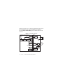
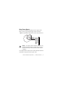
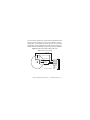
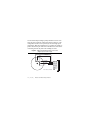
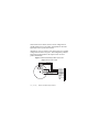
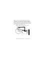
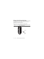
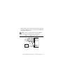
USER MANUAL AND SPECIFICATIONS NI 9503 Stepper Drive Français Deutsch ni.com/manuals This document describes how to use the National Instruments 9503 module and includes specifications and pin assignments for the NI 9503. Visit ni.com/info and enter rdsoftwareversion to determine which software you need for the modules you are using. For information about installing, configuring, and programming the system, refer to the system documentation. Visit ni.com/info and enter cseriesdoc for information about C Series documentation. Note The safety guidelines and specifications in this document are specific to the NI 9503. The other components in the system may not meet the same safety ratings and specifications. Refer to the documentation for each component in the system to determine the safety ratings and specifications for the entire system. Safety Guidelines Operate the NI 9503 only as described in these operating instructions. Hot Surface This icon denotes that the component may be hot. Touching this component may result in bodily injury. 2 | ni.com | NI 9503 User Manual and Specifications Do not operate the NI 9503 in a manner not specified in these operating instructions. Product misuse can result in a hazard. You can compromise the safety protection built into the product if the product is damaged in any way. If the product is damaged, return it to National Instruments for repair. Caution Safety Guidelines for Hazardous Locations The NI 9503 is suitable for use in Class I, Division 2, Groups A, B, C, D, T4 hazardous locations; Class I, Zone 2, AEx nA IIC T4, and Ex nA IIC T4 hazardous locations; and nonhazardous locations only. Follow these guidelines if you are installing the NI 9503 in a potentially explosive environment. Not following these guidelines may result in serious injury or death. Do not disconnect I/O-side wires or connectors unless power has been switched off or the area is known to be nonhazardous. Caution Do not remove modules unless power has been switched off or the area is known to be nonhazardous. Caution NI 9503 User Manual and Specifications | © National Instruments | 3 Substitution of components may impair suitability for Class I, Division 2. Caution For Division 2 and Zone 2 applications, install the system in an enclosure rated to at least IP 54 as defined by IEC 60529 and EN 60529. Caution For Division 2 and Zone 2 applications, install a protection device between the input signal and the Vsup pin. The device must prevent the Vsup-to-channel voltage from exceeding 42 V if there is a transient overvoltage condition. Caution For Zone 2 applications, connected signals must be within the following limit: Caution Capacitance .......................... 0.2 μF max Special Conditions for Hazardous Locations Use in Europe This equipment has been evaluated as Ex nA IIC T4 Gc equipment under DEMKO Certificate No. 12 ATEX 1202658X. Each module is marked II 3G and is suitable for use in Zone 2 hazardous locations, in ambient temperatures of 4 | ni.com | NI 9503 User Manual and Specifications -40 °C ≤ Ta ≤ 70 °C. If you are using the NI 9503 in Gas Group IIC hazardous locations, you must use the device in an NI chassis that has been evaluated as Ex nC IIC T4, EEx nC IIC T4, Ex nA IIC T4, or Ex nL IIC T4 equipment. You must make sure that transient disturbances do not exceed 140% of the rated voltage. Caution Caution The system shall be mounted in an ATEX certified enclosure with a minimum ingress protection rating of at least IP54 as defined in IEC/EN 60529 and used in an environment of not more than Pollution Degree 2. The enclosure must have a door or cover accessible only by the use of a tool. Caution Electromagnetic Compatibility Guidelines This product was tested and complies with the regulatory requirements and limits for electromagnetic compatibility (EMC) as stated in the product specifications. These requirements and limits are designed to provide reasonable protection against NI 9503 User Manual and Specifications | © National Instruments | 5 harmful interference when the product is operated in its intended operational electromagnetic environment. This product is intended for use in industrial locations. As such, there is no guarantee that harmful interference will not occur in a particular installation, when the product is connected to a test object, or if the product is used in residential areas. To minimize the potential for the product to cause interference to radio and television reception or to experience unacceptable performance degradation, install and use this product in strict accordance with the instructions in the product documentation. Furthermore, any changes or modifications to the product not expressly approved by National Instruments could void your authority to operate it under your local regulatory rules. To ensure compliance with the applicable regulatory requirements, product installation requires either special considerations or user-installed, add-on devices. See the product installation instructions for further information. Caution 6 | ni.com | NI 9503 User Manual and Specifications The inputs/outputs of this product can be damaged if subjected to Electrostatic Discharge (ESD). To prevent damage, industry-standard ESD prevention measures must be employed during installation, maintenance, and operation. Caution Special Guidelines for Marine Applications Some products are Lloyd’s Register (LR) Type Approved for marine (shipboard) applications. To verify Lloyd’s Register certification for a product, visit ni.com/certification and search for the LR certificate, or look for the Lloyd’s Register mark on the product label. In order to meet the EMC requirements for marine applications, install the product in a shielded enclosure with shielded and/or filtered power and input/output ports. In addition, take precautions when designing, selecting, and installing measurement probes and cables to ensure that the desired EMC performance is attained. Caution NI 9503 User Manual and Specifications | © National Instruments | 7 NI 9503 Hardware Overview The NI 9503 is a stepper motor drive for use with 2-phase hybrid stepper motors in either bipolar or unipolar winding configuration. It uses software-programmable control algorithms that reduce torque ripple, dampen high-speed resonance, and implements smoother motion during microstepping. The NI 9503 returns the motor current and bus voltage to the LabVIEW FPGA module for use in a current PI loop and antiresonance algorithms. NI 9503 status information such as drive status and drive faults are also returned to the LabVIEW FPGA module. Refer to the NI 9503 topic in the LabVIEW Help, available by selecting Help»LabVIEW Help, for information about the available status information. Note National Instruments offers NEMA 8, NEMA 11, NEMA 14, NEMA 17 and NEMA 23 stepper motors compatible with the NI 9503. Go to ni.com/motion/ stepper for more information about NI stepper motors. The NI 9503 reduces torque ripple at speeds near 1 RPS that are caused by fourth harmonic disturbances. The torque ripple smoothing algorithm is software programmable and can be tuned 8 | ni.com | NI 9503 User Manual and Specifications for any motor. Motors supported by National Instruments have already been tuned for optimal torque smoothing. The NI 9503 uses a software-programmable antiresonance algorithm to reduce stepper motor resonance above 2 RPS. The antiresonance algorithm allows a stepper motor to use more available torque and run at higher speeds without stalling. The NI 9503 supports software-programmable microstepping. Microstepping divides full steps into smaller steps to create smoother motion. The NI 9503 supports microstepping rates up to 256. When full-stepping, a resonance can occur, causing vibration and reducing the motor torque. The NI 9503 offers the best performance when combining microstepping with the torque smoothing and antiresonance properties. Refer to the Step Resolver topic in the LabVIEW Help, available by selecting Help» LabVIEW Help, for information about microstepping options. The NI 9503 allows for phase current reduction after the motor stops moving. Unlike servo motors, stepper motor coils remain fully energized when the motor is not moving. This allows for strong holding torque, but generates substantial heat in the motor. Many applications do not require maximum holding torque when the motor is at rest, which means that the motor is wasting power. The amount of current reduction and delay before current NI 9503 User Manual and Specifications | © National Instruments | 9 reduction becomes active is software-programmable. Refer to the Current Scheduler topic in the LabVIEW Help, available by selecting Help»LabVIEW Help, for information about current reduction. Figure 1. NI 9503 Block Diagram LabVIEW FPGA Module with SoftMotion Correction Angle Position Setpoint Step Resolver Current Scheduler Antiresonance NI 9503 Bus voltage Bridge Controller Phase A & B Current Fault Monitor | ni.com | + COM – Current Loop PWM Generator 10 Vsup Power Stage Current Sense Fault Detection NI 9503 User Manual and Specifications Motor Connecting the NI 9503 The NI 9503 has a 10-terminal detachable screw-terminal connector that provides connections for the stepper motor signals, a motor DC power supply, COM, and chassis ground. Refer to Figure 2 for the pin assignments. To ensure EMC compliance, special considerations are required for all cable connections. Refer to the Cable Requirements for EMC Compliance section. Caution Note You must use 2-wire ferrules to create a secure connection when connecting more than one wire to a single terminal on the NI 9503 screw terminal. Do not turn on or plug in the motor DC power supply until the screw-terminal connector is fully inserted. Caution NI 9503 User Manual and Specifications | © National Instruments | 11 Figure 2. NI 9503 Connections Phase A+ Phase A– Phase B+ Phase B– Reserved Reserved Reserved COM Vsup (Chassis Ground) 12 | ni.com | NI 9503 User Manual and Specifications 0 1 2 3 4 5 6 7 8 9 Motor Power Signals The Phase A± and Phase B± signals power the stepper motor. Figure 3 shows a typical bipolar stepper motor connection. Figure 3. Typical Bipolar Stepper Motor (2-Phase Type) Connection Red Blue Yellow White Phase A+ Phase A– Phase B+ Phase B– Phase A+ Phase A– Phase B+ Phase B– Reserved Reserved Reserved COM Vsup 0 1 2 3 4 5 6 7 8 9 The stepper motor terminals on this drive are energized when the module is enabled. Do not connect wires to or disconnect wires from the NI 9503 when it is enabled. Caution Use a multiconductor cable with an overall shield and conductors of 20 AWG or larger for the motor power cable. NI 9503 User Manual and Specifications | © National Instruments | 13 The NI 9503 contains a highly efficient power stage. Two-phase stepper motors come in 4-, 6-, and 8-wire variations. You must wire the stepper motors in a 4-wire configuration as shown in Figure 3. Never connect unused stepper motor terminals to pin 9 (Chassis Ground) or to each other. Caution When using a 6- or 8-wire stepper motor you must leave unused lead wires disconnected. Figure 4 shows a 6-wire and an 8-wire stepper motor. Figure 4. 6-Wire and 8-Wire Stepper Motors 6-wire 14 | ni.com | 8-wire NI 9503 User Manual and Specifications A 4-wire motor is the same as a 6-wire motor except that the center taps (CT) are not brought out. To use a 6-wire motor in a 4-wire configuration you can isolate the center taps for a series (full coil) configuration. Series configurations produce the most torque per amp but have the disadvantage of poorer high-speed performance. Figure 5. 6-Wire Series Stepper Motor Connection (Higher Torque, Lower Speed) Phase A+ NC* Phase A– Phase B+ Phase A+ Phase A– Phase B+ Phase B– Reserved Reserved Reserved COM Vsup NC* Phase B– 0 1 2 3 4 5 6 7 8 9 *NC = Not Connected NI 9503 User Manual and Specifications | © National Instruments | 15 You can obtain improved high-speed performance with a 6-wire motor by using a half-coil configuration shown in Figure 6. This configuration sacrifices low-speed torque for better high-speed performance. With this configuration, it is typically not possible to produce the rated torque of the motor without the risk of the motor overheating because only half of the windings are used. Figure 6. 6-Wire Half-Coil Stepper Motor Connection (Higher Speed, Lower Torque) Phase A+ Phase A– NC* Phase B+ Phase B– NC* *NC = Not Connected 16 | ni.com | NI 9503 User Manual and Specifications Phase A+ Phase A– Phase B+ Phase B– Reserved Reserved Reserved COM Vsup 0 1 2 3 4 5 6 7 8 9 For maximum flexibility, you can connect 8-wire stepper motors in series, parallel, or half-coil configurations. Connecting the windings in a series configuration, as shown in Figure 7, produces the most torque per amp but has the disadvantage of higher inductance and poorer high-speed performance. Figure 7. 8-Wire Series Stepper Motor Connection (Higher Torque, Lower Speed) Phase A+ Blk/Wht Black Org/Wht Orange Phase A– Red Red/Wht Yel/Wht Yellow Phase B+ Phase B– NI 9503 User Manual and Specifications | Phase A+ Phase A– Phase B+ Phase B– Reserved Reserved Reserved COM Vsup 0 1 2 3 4 5 6 7 8 9 © National Instruments | 17 Notice that an 8-wire motor wired in a series configuration is virtually identical to a 6-wire motor and typically has the same high torque but low-speed characteristics. Alternatively, you can connect 8-wire stepper motors in a parallel configuration as shown in Figure 8. This configuration produces better high-speed performance but requires more current to produce rated torque. Figure 8. 8-Wire Parallel Stepper Motor Connection (Higher Speed, Lower Torque) Black Blk/Wht Org/Wht Orange Phase A+ Phase A– Red Red/Wht Yel/Wht Phase B+ Phase B– Yellow 18 | ni.com | NI 9503 User Manual and Specifications Phase A+ Phase A– Phase B+ Phase B– Reserved Reserved Reserved COM Vsup 0 1 2 3 4 5 6 7 8 9 Finally, you can connect 8-wire stepper motors in a half-coil configuration as shown in Figure 9. The half-coil configuration sacrifices low-speed torque for better high-speed performance. With this configuration, it is typically not possible to produce the rated torque of the motor without the risk of the motor overheating because only half of the windings are used. Figure 9. 8-Wire Half-Coil Stepper Motor Connection Phase A+ Phase A– NC NC Phase B+ Phase A+ Phase A– Phase B+ Phase B– Reserved Reserved Reserved COM Vsup Phase B– NC NC 0 1 2 3 4 5 6 7 8 9 *NC = Not Connected NI 9503 User Manual and Specifications | © National Instruments | 19 Wiring for High Vibration Applications If an application is subject to high vibration, National Instruments recommends that you use ferrules to terminate wires to the detachable screw-terminal connector. Refer to Figure 10 for an illustration of using ferrules. Figure 10. 10-Terminal Detachable Screw-Terminal Connector with Ferrule Terminated Wire Ferrule 20 | ni.com | NI 9503 User Manual and Specifications LED Indicators The NI 9503 has four LEDs to display status information. 1 2 3 1 Enabled (green) 2 Vsup (Motor Power) (green) 4 3 User (yellow) 4 Fault (red) Enabled The Enabled LED (green) illuminates when the drive is enabled and the output power stage is active, and is flashing when the drive is disabled and the output power stage is inactive. Refer to the NI 9503 topic in the LabVIEW Help, available by selecting Help» LabVIEW Help, for information about enabling the drive. Vsup The Vsup LED (green) illuminates when the motor DC power supply is properly connected. NI 9503 User Manual and Specifications | © National Instruments | 21 User You can define the User LED (yellow) to meet the needs of your application. Use the User LED I/O node to turn this LED on and off. Refer to the NI 9503 topic in the LabVIEW Help, available by selecting Help»LabVIEW Help, for information about the NI 9503 User LED I/O node. Fault If the Fault LED is lit, determine the cause of the fault and correct it before enabling the drive. Caution The Fault LED (red) illuminates when a fault occurs. A fault disables the drive. Causes for fault are the following: • Vsup undervoltage Vsup greater than 40 V will result in damage to the NI 9503. Caution • Vsup overvoltage • Overcurrent 22 | ni.com | NI 9503 User Manual and Specifications Hot-Swap Behavior The NI 9503 is always disabled when it is first inserted in the chassis, regardless of whether Vsup is present or not. You can enable the drive using the Enable Drive method in software. Refer to the NI 9503 topic in the LabVIEW Help, available by selecting Help»LabVIEW Help, for more information about enabling the drive. When the NI 9503 is removed from the chassis while it is enabled, the power to the motor is removed and the motor decelerates to a stop based on its own friction. Sleep Mode This module supports a low-power sleep mode. Support for sleep mode at the system level depends on the chassis that the module is plugged into. Refer to the chassis manual for information about support for sleep mode. If the chassis supports sleep mode, refer to the software help for information about enabling sleep mode. Visit ni.com/info and enter cseriesdoc for information about C Series documentation. NI 9503 User Manual and Specifications | © National Instruments | 23 Typically, when a system is in sleep mode, you cannot communicate with the modules. In sleep mode, the system consumes minimal power and may dissipate less heat than it does in normal mode. Refer to the Specifications section for more information about power consumption and thermal dissipation. Cable Requirements for EMC Compliance Select and install cables for the NI 9503 in accordance with the following requirements: • Do not tie the motor case to the NI 9503 chassis ground. • Use only shielded cables to connect the NI 9503 to a motor and a power supply. • Terminate the motor and power supply cable shields to the COM terminal of the NI 9503. In addition, terminate the cable shields at the other end to either earth ground or the chassis of the connected motor and/or power supply. 24 | ni.com | NI 9503 User Manual and Specifications • Install a clamp-on ferrite bead onto both the motor cable and Vsup cable, as shown in Figure 11. Power to the module must be off when adding ferrites. Note The wire connecting the motor cable shield to COM bypasses the ferrite as shown in Figure 11. Figure 11. NI 9503 Cable Connection NI 9501 Phase A+ Phase A– Phase B+ Phase B– Motor Shield Motor DC Power Supply Ferrites NI 9503 User Manual and Specifications COM Vsup | © National Instruments | 25 Clamp-on ferrites must be connected to the motor cable and Vsup cable as close to the module as possible with a full turn as shown in Figure 12. Placing the ferrite elsewhere on the cable noticeably impairs its effectiveness. Figure 12. Installing a Ferrite • 26 Determine the clamp-on ferrite beads to install based on twice the motor cable and Vsup cable diameter. Order the appropriate ferrite beads from NI. | ni.com | NI 9503 User Manual and Specifications NI Part Number Aperture Size mm (inches) 781233-01 7.0 (0.275) 781233-02 10.2 (0.402) 777297-01 13.4 (0.528) Specifications The following specifications are typical for the temperature range -40 to 70 °C unless otherwise noted. All voltages are relative to COM unless otherwise noted. Input/Output Characteristics Motor DC power supply (Vsup) ....... +9 to +30 VDC Minimum phase inductance.............. 1 mH Maximum phase inductance ............. 20 mH Type .................................................. PWM PWM frequency................................ 20 kHz Current per phase.............................. 3 A RMS (4.24 A peak) NI 9503 User Manual and Specifications | © National Instruments | 27 Current reduction .............................. 0% to 99% (software-selectable) Microstepping selections .................. x2, 4, 8, 16, 32, 64, 128, 256 (software-selectable) Vsup capacitance .............................. 750 μF MTBF ............................................... Contact NI for Bellcore MTBF specifications. Drive Protection Undervoltage..................................... <6 V Vsup greater than 40 V will result in damage to the module. Caution Overvoltage....................................... >32 V Power Requirements Power consumption from chassis Active mode ............................... 500 mW max Sleep mode ................................. 2.5 mW max 28 | ni.com | NI 9503 User Manual and Specifications Thermal dissipation (at 70 °C) Active mode ............................... 1.5 W max Sleep mode ................................. 2.5 mW max Physical Characteristics If you need to clean the module, wipe it with a dry towel. Note For two-dimensional drawings and three-dimensional models of the C Series module and connectors, visit ni.com/dimensions and search by module number. Screw terminal wiring Gauge ......................................... 12 to 24 AWG copper conductor wire with 10 mm (0.39 in.) of insulation stripped from the end Temperature rating ..................... 85 °C min. Wires per screw terminal .................. One wire per screw terminal, two when using 2-wire ferrule NI 9503 User Manual and Specifications | © National Instruments | 29 Ferrules ............................................. 0.25 mm2 to 2.5 mm2 Torque for screw terminals ............... 0.5 to 0.6 N · m (4.4 to 5.3 lb · in.) Connector securement Securement type ......................... Screw flanges provided Torque for screw flanges ............ 0.2N · m (1.8 lb · in.) Weight............................................... 144 g (5.1 oz) Safety Safety Voltages Connect only voltages that are within the following limits. Channel-to-COM .............................. 0 to +30 VDC max, Measurement Category I Isolation Channel-to-channel .................... None Channel-to-earth ground Continuous ........................... 60 VDC, Measurement Category I Withstand ............................. 1000 Vrms, verified by a 5 s dielectric withstand test 30 | ni.com | NI 9503 User Manual and Specifications Measurement Category I is for measurements performed on circuits not directly connected to the electrical distribution system referred to as MAINS voltage. MAINS is a hazardous live electrical supply system that powers equipment. This category is for measurements of voltages from specially protected secondary circuits. Such voltage measurements include signal levels, special equipment, limited-energy parts of equipment, circuits powered by regulated low-voltage sources, and electronics. Caution Do not connect the NI 9503 to signals or use for measurements within Measurement Categories II, III, or IV. Note Measurement Categories CAT I and CAT O (Other) are equivalent. These test and measurement circuits are not intended for direct connection to the MAINs building installations of Measurement Categories CAT II, CAT III, and CAT IV. NI 9503 User Manual and Specifications | © National Instruments | 31 Hazardous Locations U.S. (UL) .......................................... Class I, Division 2, Groups A, B, C, D, T4; Class I, Zone 2, AEx nA IIC T4 Canada (C-UL) ................................. Class I, Division 2, Groups A, B, C, D, T4; Class I, Zone 2, Ex nA IIC T4 Europe (DEMKO) ............................ Ex nA IIC T4 Gc Power Supply Requirements Safety and Hazardous Locations Standards The NI 9503 is designed to meet the requirements of the following standards of safety for electrical equipment for measurement, control, and laboratory use: • IEC 61010-1, EN 61010-1 • UL 61010-1, CSA 61010-1 • EN 60079-0:2012, EN 60079-15:2010 • IEC 60079-0: Ed 6, IEC 60079-15: Ed 4 32 | ni.com | NI 9503 User Manual and Specifications • UL 60079-0: Ed 5, UL 60079-15: Ed 3 • CSA 60079-0:2011, CSA 60079-15:2012 Note For UL and other safety certifications, refer to the product label or the Online Product Certification section. Electromagnetic Compatibility This product meets the requirements of the following EMC standards for electrical equipment for measurement, control, and laboratory use: • EN 61326-1 (IEC 61326-1): Class A emissions; Industrial immunity • EN 55011 (CISPR 11): Group 1, Class A emissions • AS/NZS CISPR 11: Group 1, Class A emissions • FCC 47 CFR Part 15B: Class A emissions • ICES-001: Class A emissions Note For the standards applied to assess the EMC of this product, refer to the Online Product Certification section. NI 9503 User Manual and Specifications | © National Instruments | 33 Note For EMC compliance, operate this device with shielded cabling. CE Compliance This product meets the essential requirements of applicable European directives as follows: • 2006/95/EC; Low-Voltage Directive (safety) • 2004/108/EC; Electromagnetic Compatibility Directive (EMC) • 94/9/EC; Potentially Explosive Atmosphere (ATEX) Online Product Certification Refer to the product Declaration of Conformity (DoC) for additional regulatory compliance information. To obtain product certifications and the DoC for this product, visit ni.com/ certification, search by module number or product line, and click the appropriate link in the Certification column. 34 | ni.com | NI 9503 User Manual and Specifications Shock and Vibration To meet these specifications, you must panel mount the system and affix ferrules to the end of the screw terminal wires. Operating vibration Random (IEC 60068-2-64)......... 5 grms, 10 to 500 Hz Sinusoidal (IEC 60068-2-6) ....... 5 g, 10 to 500 Hz Operating shock (IEC 60068-2-27).............................. 30 g, 11 ms half sine, 50 g, 3 ms half sine, 18 shocks at 6 orientations Environmental National Instruments C Series modules are intended for indoor use only. Refer to the manual for the chassis you are using for more information about meeting these specifications. Operating temperature (IEC 60068-2-1, IEC 60068-2-2) ..... -40 to 70 °C Storage temperature (IEC 60068-2-1, IEC 60068-2-2) ..... -40 to 85 °C Ingress protection.............................. IP 40 NI 9503 User Manual and Specifications | © National Instruments | 35 Operating humidity (IEC 60068-2-56).............................. 10 to 90% RH, noncondensing Storage humidity (IEC 60068-2-56).............................. 5 to 95% RH, noncondensing Maximum altitude............................. 2,000 m Pollution Degree (IEC 60664) .......... 2 Indoor use only. Environmental Management NI is committed to designing and manufacturing products in an environmentally responsible manner. NI recognizes that eliminating certain hazardous substances from our products is beneficial to the environment and to NI customers. For additional environmental information, refer to the Minimize Our Environmental Impact web page at ni.com/environment. This page contains the environmental regulations and directives with which NI complies, as well as other environmental information not included in this document. 36 | ni.com | NI 9503 User Manual and Specifications Waste Electrical and Electronic Equipment (WEEE) EU Customers At the end of the product life cycle, all products must be sent to a WEEE recycling center. For more information about WEEE recycling centers, National Instruments WEEE initiatives, and compliance with WEEE Directive 2002/96/EC on Waste and Electronic Equipment, visit ni.com/environment/ weee. ⬉ᄤֵᙃѻક∵ᶧࠊㅵ⧚ࡲ⊩ ˄Ё RoHS˅ Ёᅶ᠋ National Instruments ヺড়Ё⬉ᄤֵᙃ ѻકЁ䰤ࠊՓ⫼ᶤѯ᳝ᆇ⠽䋼ᣛҸ (RoHS)DŽ݇Ѣ National Instruments Ё RoHS ড়㾘ᗻֵᙃˈ䇋ⱏᔩ ni.com/environment/rohs_chinaDŽ (For information about China RoHS compliance, go to ni.com/ environment/rohs_china.) NI 9503 User Manual and Specifications | © National Instruments | 37 Worldwide Support and Services The National Instruments website is your complete resource for technical support. At ni.com/support you have access to everything from troubleshooting and application development self-help resources to email and phone assistance from NI Application Engineers. Visit ni.com/services for NI Factory Installation Services, repairs, extended warranty, and other services. Visit ni.com/register to register your National Instruments product. Product registration facilitates technical support and ensures that you receive important information updates from NI. A Declaration of Conformity (DoC) is our claim of compliance with the Council of the European Communities using the manufacturer’s declaration of conformity. This system affords the user protection for electromagnetic compatibility (EMC) and product safety. You can obtain the DoC for your product by visiting ni.com/certification. If your product supports calibration, you can obtain the calibration certificate for your product at ni.com/calibration. 38 | ni.com | NI 9503 User Manual and Specifications National Instruments corporate headquarters is located at 11500 North Mopac Expressway, Austin, Texas, 78759-3504. National Instruments also has offices located around the world. For telephone support in the United States, create your service request at ni.com/support or dial 1 866 ASK MYNI (275 6964). For telephone support outside the United States, visit the Worldwide Offices section of ni.com/niglobal to access the branch office websites, which provide up-to-date contact information, support phone numbers, email addresses, and current events. Refer to the NI Trademarks and Logo Guidelines at ni.com/trademarks for more information on National Instruments trademarks. Other product and company names mentioned herein are trademarks or trade names of their respective companies. For patents covering National Instruments products/technology, refer to the appropriate location: Help»Patents in your software, the patents.txt file on your media, or the National Instruments Patent Notice at ni.com/patents. You can find information about end-user license agreements (EULAs) and third-party legal notices in the readme file for your NI product. Refer to the Export Compliance Information at ni.com/legal/export-compliance for the National Instruments global trade compliance policy and how to obtain relevant HTS codes, ECCNs, and other import/export data. NI MAKES NO EXPRESS OR IMPLIED WARRANTIES AS TO THE ACCURACY OF THE INFORMATION CONTAINED HEREIN AND SHALL NOT BE LIABLE FOR ANY ERRORS. U.S. Government Customers: The data contained in this manual was developed at private expense and is subject to the applicable limited rights and restricted data rights as set forth in FAR 52.227-14, DFAR 252.227-7014, and DFAR 252.227-7015. © 2014 National Instruments. All rights reserved. 375481A-01 Aug14