1
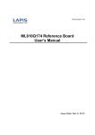
Introduction
The LPC2294 and LPC2214 are based on a 16/32 bit ARM7TDMI-S™ CPU with real-time emulation and embedded trace support, together with
128/256 kilobytes (kB) of embedded high speed flash memory. A 128-bit wide memory interface and a unique accelerator architecture enable 32-bit
code execution at maximum clock rate. For critical code size applications, the alternative 16-bit Thumb Mode reduces code by more than 30% with
minimal performance penalty.
With their 144 pin package, low power consumption, various 32-bit timers, 8-channel 10-bit ADC, PWM channels and up to 9 external interrupt pins
these microcontrollers are particularly suitable for industrial control, medical systems, access control and point-of-sale. Number of available GPIOs
ranges from 76 (with external memory) through 112 pins (single-chip). With a wide range of serial communications interfaces, they are also very well
suited for communication gateways, protocol converters and embedded soft modems as well as many other general-purpose applications.
The LPC E2214 Development board is designed to evaluate LPC2214 processor. It has the following features:
•
•
•
•
•
•
•
•
•
•
•
•
•
•
•
•
•
•
•
MCU: LPC2214 16/32 bit ARM7TDMI-S™t with 256K Bytes Program Flash, 16K Bytes RAM, EXTERNAL MEMORY BUS, RTC,4x 10 bit ADC
2.44 uS, 2x UARTs, 2x 32bit TIMERS, 7x CCR, 6x PWM, WDT, 5V tolerant I/O, up to 60MHz operation
Standard JTAG connector with ARM 2x10 pin layout for programming/debugging with ARM-JTAG
1MB (256Kx32bit) 8/10 ns K6R4016V1D SRAM
1MB (512Kx16bit) 55/70ns MX26LV800T FLASH
USB to RS232 converter
RESET circuit with external control of Philips ISP utility via USB-RS232 virtual port
Jumpers for boot select from external memory
Jumpers for ISP/RUN mode
Ethernet controller with DM9000E and RJ45 connector
LCD 16x2 DISPLAY with BACKLIGHT
2 BUTTONS
SD/MMC connector
POTENTIOMETER connected to AIN0
RS232 driver and connector
UEXT connector
Single power supply: 6V AC or 9V DC required
Power supply LED
Power supply filtering capacitor
Two on board voltage regulators 1.8V and 3.3V with up to 800mA current
The LPC E2294 Development board is designed to evaluate LPC2294 processor. It has the following features:
•
•
•
•
•
•
•
•
•
•
•
•
•
•
•
•
•
•
•
•
MCU: LPC2294 16/32 bit ARM7TDMI-S™t with 256K Bytes Program Flash, 16K Bytes RAM, EXTERNAL MEMORY BUS, RTC,4x 10 bit ADC
2.44 uS, 2x UARTs, 4x CAN, 2x 32bit TIMERS, 7x CCR, 6x PWM, WDT, 5V tolerant I/O, up to 60MHz operation
Standard JTAG connector with ARM 2x10 pin layout for programming/debugging with ARM-JTAG
1MB (256Kx32bit) 8/10 ns K6R4016V1D SRAM
2MB (1Mx16bit) 70ns TE28F160C3 C3 INTEL FLASH
USB to RS232 converter,
4 CAN drivers and connectors
RESET circuit with external control of Philips ISP utility via USB-RS232 virtual port
Jumpers for boot select from external memory
Jumpers for ISP/RUN mode
Ethernet controller with DM9000E and RJ45 connector
LCD 16x2 DISPLAY with BACKLIGHT
2 BUTTONS
SD/MMC connector
POTENTIOMETER connected to AIN0
RS232 driver and connector
UEXT Connector
Single power supply: 6V AC or 9V DC required
Power supply LED
Power supply filtering capacitor
Two on board voltage regulators 1.8V and 3.3V with up to 800mA current
Board LPC E22x4 (depends of MCU: LPC2214 or LPC2294)
Peripherals
Unit
Description
COM Port (RS232)
RS232 DB9 Female connector for LPC2294 UART0.
CAN1
CAN DB9 Male connector for LPC CAN1 Interface (LPC-E2294 only)
CAN2
CAN DB9 Male connector for LPC CAN2 Interface (LPC-E2294 only)
CAN3
CAN DB9 Male connector for LPC CAN3 Interface (LPC-E2294 only)
CAN4
CAN DB9 Male connector for LPC CAN4 Interface (LPC-E2294 only)
SD/MMC connector
Connector for external SD/MMC cards.
LCD Display
2X16 LCD Display
JTAG Connector
2x10 0.1" step connector for JTAG programming .
UEXT Connector
2x5 0.1” step connector
USB/ICSP connector
USB connector Type B for LPC UART0 interface.
LAN Connector
Ethernet controller with DM9000E and RJ45 connector
SRAM Memory
LPC E2214: 1MB (256Kx32bit) 12 ns K6R4016V1D SRAM connected to CS1
LPC E2294: 1MB (256Kx32bit) 12 ns K6R4016V1D SRAM connected to CS1
Flash Memory
LPC E2214: 1MB (512Kx16bit) 70ns MX26LV800T connected FLASH to CS0
LPC E2294: 2MB (1Mx16bit) 70ns TE28F160C3 C3 FLASH connected to CS0
Buttons
Two buttons connected to interrupt ports - P0.15 (pin 99) and P0.16 (pin 100) and Reset button
Leds
Power supply indicator for board (PWR).
Technical characteristics
Parameter
Description
Voltage Supply
min 9.0V DC, max 12.0V DC
min 6.0V AC, max 9.0V AC
or
+5V from USB (depending from EXT/USB jumper)
CPU
LPC E2214 -> LPC2214
LPC E2294 -> LPC2294
Crystals
Q1 - 14.7456 MHz HF crystal
Q3 - 25 MHz
Q4 – 6 MHz
Board dimensions
171 x 99 mm (6.7 x 3.9 ")
PCB
FR-4, 1.5 mm (0,062"), green solder mask, white silkscreen component print
Operating Temperature
form 0ºC to 70ºC
JTAG Connector
Pin / Name
1 - VCC
2 - VCC
3 - TRST
4 - GND
5 - TDI
6 - GND
7 - TMS
8 - GND
9 - TCK
10 - GND
11 - RTCK
12 - GND
13 - TDO
14 - GND
15 - RST
16 - GND
17 - 18 - GND
19 - 20 - GND
Connected to:
VCC
VCC
PIN 43
GROUND
PIN 140
GROUND
PIN 113
GROUND
PIN 126
GROUND
GROUND via jumper
GROUND
PIN 144
GROUND
PIN 135
GROUND
no connected
GROUND
no connected
GROUND
Functionality
P1.31/TRST
P1.28/TDI
P1.30/TMS
P1.29/TCK
P1.27/TDO
RST
-
Pin / Name
1 - +3.3V
2 - GND
3 - TXD1
4 - RXD1
5 - SCL
6 - SDA
7 - MISO1
8 - MOSI1
9 - SCLK1
10 - SPI1_CS
Connected to:
+3.3V
GROUND
PIN 75
PIN 76
PIN 50
PIN 58
PIN 121
PIN 122
PIN 101
PIN 123
Functionality
P0.8 / TXD1 / PWM4
P0.9 / RXD1 / PWM6 / EINT3 (via jumper)
P0.2 / SCL / CAP 0.0
P0.3 / SDA / MAT0.0 / EINT1
P0.18 / CAP1.3 / MISO1 / MAT1.3
P0.19 / MAT1.2 / MOSI1 / CAP1.2
P0.17 / CAP1.2 / SCK1 / MAT1.2
P0.20 / MAT1.3 / SSEL1 / EINT3
Pin / Name
1 - CD
2 - TXD
3 - RXD
4 - DTR
5 - GND
6 - DSR
7 - RTS
8 - CTS
9 - RI
Connected to:
not connected
PIN 75
PIN 76
not connected
GROUND
not connected
not connected
not connected
not connected
Functionality
P0.8 / TXD1 / PWM4
P0.9 / RXD1 / PWM6 / EINT3 (via jumper)
-
Pin / Name
2 - CANL
3 - GND
7 - CANH
Connected to:
CAN LOW
GROUND
CAN HIGH
Functionality
-
UEXT extension
RS232 Connector
CAN Connector (CAN1)
- MCP2551 (U7) is connected to LPC CAN1 Interface (TD1 and RD1)
- CANL and CANH are connected via CAN1_T jumper
CAN Connector (CAN2)
Pin / Name
2 - CANL
3 - GND
7 - CANH
Connected to:
CAN LOW
GROUND
CAN HIGH
Functionality
-
- MCP2551 (U6) is connected to LPC CAN2 Interface (TD2 and RD2)
- CANL and CANH are connected via CAN2_T jumper
CAN Connector (CAN3)
Pin / Name
2 - CANL
3 - GND
7 - CANH
Connected to:
CAN LOW
GROUND
CAN HIGH
Functionality
-
- MCP2551 (U8) is connected to LPC CAN3 Interface (TD3 and RD3)
- CANL and CANH are connected via CAN3_T jumper
CAN Connector (CAN4)
Pin / Name
2 - CANL
3 - GND
7 - CANH
Connected to:
CAN LOW
GROUND
CAN HIGH
Functionality
-
- MCP2551 (U9) is connected to LPC CAN4 Interface (TD4 and RD4)
- CANL and CANH are connected via CAN4_T jumper
USB/ICSP Connector
Pin / Name
1 - +5V
2 - USBDM
3 - USBDP
4 - GND
Connected to:
+5V DC
FT232BM (PIN 8)
FT232BM (PIN 7)
GROUND
Functionality
USBDM
USBDP
-
LAN Connector
Pin / Name
1 - TD+
2 - TD3 - +3.3V
AG
KG (SPEED/DUP)
AY
KY (LINK_ACT)
6 - RTC
7 - RD+
8 - RD-
Connected to:
DM9000E PIN 33
DM9000E PIN 34
+3.3V
+3.3V
PIN60 or PIN61
+3.3V
PIN 62
DM9000E PIN 29
DM9000E PIN 30
Functionality
TXD+
TXDRXD+
Notice: depends of smd jumper SPEED/DUP
RXDLINKACT
RD+
RD-
SD/MMC Connector
Pin / Name
1 - CD/DAT3/CS
2 - CMD/DI
3 - VSS1
4 - VDD
5 - CLK/SCLK
6 - VSS2
7 - DAT0/DO
8 - DAT1/RES
9 - DAT2/RES
10 - WP1
14 - WP2
13 - CP1
15 - CP2
Connected to:
PIN 36 or PIN 123
PIN 122
GROUND
+3.3V
PIN 101
GROUND
PIN 121
+3.3V
+3.3V
PIN 70
GROUND
PIN 60
GROUND
Functionality
P3.24 / CS3 or P0.20 / MAT1.3 / SSEL1 / EINT3
P0.19 / MAT1.2 / MOSI1 / CAP1.2
P0.17 / CAP1.2 / SCK1 / MAT1.2
P0.18 / CAP1.3 / MISO1 / MAT1.3
P1.24 / TRACECLK
P1.25 / EXTIN0
P1.15 / HTXD
Jumpers
Jumpers
Position
Description
Disable ICSP programming.
Jumper (JRST)
Jumper (BSL)
Enable ICSP programming - via USB (virtual COM port)
Jumper (CAN1_T)
Jumper (CAN1_D)
Jumper (CAN2_T)
Jumper (CAN2_D)
Jumper (CAN3_T)
Jumper (CAN3_D)
Jumper (CAN4_T)
Jumper (CAN4_D)
CAN1 Terminator disable
CAN1 Terminator enable (120 ohm)
CAN1 Driver enable
CAN1 Driver disable
CAN2 Terminator disable
CAN2 Terminator enable (120 ohm)
CAN2 Driver enable
CAN2 Driver disable
CAN3 Terminator disable
CAN3 Terminator enable (120 ohm)
CAN3 Driver enable
CAN3 Driver disable
CAN4 Terminator disable
CAN4 Terminator enable (120 ohm)
CAN4 Driver enable
CAN4 Driver disable
Selects 8-bit memory on CS0 for boot.
Selects 16-bit memory on CS0 for boot.
Jumper (BOOT1)
Jumper (BOOT0)
Selects 32-bit memory on CS0 for boot.
Selects Internal Flash memory.
Jumper (RS232/UEXT)
Jumper (SPI_S/SPI_M)
Port P0.9/RXD1/PWM6/EINT3 (pin 76) connected to UEXT Extension port
Port P0.9/RXD1/PWM6/EINT3 (pin 76) connected to LPC UART1 interface
CS pin on SD/MMC connector is connected to P0.20 / MAT1.3 / SSEL1 / EINT3 (pin 123)
CS pin on SD/MMC connector is connected to P3.24 / CS3 (pin 36)
Jumper (EXT/USB)
External power supply (power jack connector )
USB power supply.
Jumper (DBG_E)
SMD Jumper:
Disable JTAG programming.
Enable JTAG programming.
SPEED/DUP - KG lan pin connected to DM9000E PIN 60 (#SPEED) or PIN 61(#DUP)