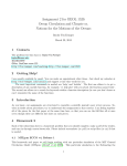
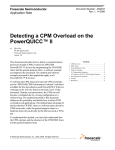
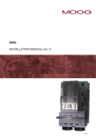
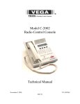
1
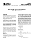
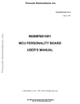
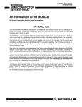
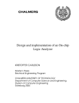
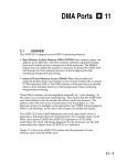
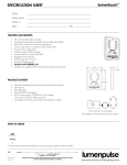
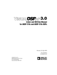
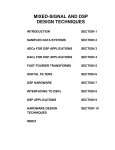
a Engineer To Engineer Note EE-115
Technical Notes on using Analog Devices’ DSP components and development tools
Phone: (800) ANALOG-D, FAX: (781) 461-3010, EMAIL: [email protected], FTP: ftp.analog.com, WEB:
www.analog.com/dsp
ADSP-2189 IDMA Interface to Motorola MC68300
Family of Microprocessors
Note: This is the modified AN-415 Application Note for the ADSP-2189 and the new tools
INTRODUCTION
The speed and mathematical capabilities of DSP
processors, combined with their low cost and
expanded integration, make them a natural choice
for use as signal co-processors in embedded
environments. When paired with a host
microprocessor, a DSP processor allows for a very
powerful and flexible system at a reasonable price.
The ADSP-2189 is an ideal candidate for use in a
co-processing system. The 192K Bytes on chip
RAM, configured as 32K words of on-chip Program
Memory RAM and 48 K words on chip Data Memory
RAM and extensive DMA and peripheral interface
features allow the ADSP-2189 to function with
minimal external support circuitry. In order to realize
the highest possible performance in a co-processor
system, efficient host-DSP communication is vital.
The popular Motorola M68300 Family of
microcontrollers provides a powerful and flexible
bus interface that is easily adaptable to a coprocessing system. This application note describes
an example hardware and software interface
between the Internal DMA (IDMA) Port of the ADSP2189 and the Motorola M68300 Family of
microcontrollers. As each specific system design
has its own requirements and challenges, this
application note does not presume to provide the
only possible solution. Rather it is meant to provide
the system designer a flexible framework of ideas
that can be tailored to meet individual system
requirements.
The DSP memory address is loaded into the IDMA
Address register (IDMAA) shown in Figure 2. This
register contains the 14-bit internal memory
address, along with a bit to specify the type of
transfer: 24-bit Program Memory opcodes, or 16-bit
Data Memory data. The IDMAA register can be
initialized by either the DSP or by a host processor.
The host can initialize this register by performing an
address latch cycle. An address latch cycle is
defined by the host asserting the ALE signal, and
then transferring a 15-bit (14 address bits plus 1
destination memory type bit) value on the IAD pins.
If Bit 15 is set to 0, IDMA latches the address. If Bit
15 is set to 1, IDMA latches into the OVERLAY
register. This register, as shown in Figure 2, is
memory mapped at address DM (0x3FE0). Note
that the host cannot read the latched address
(IDMAA) back.
H o st sta rts ID M A tra n sfe r.
H o st c he c ks IA C K c o ntro llin e
to se e if the D SP is b usy.
H o st use s IS a n d IA L c o ntro llin e s to la tc h e ith e r the D M A
sta rtin g a d d re ss (ID M A A ) o r the PM /D M O V LAY se le c tio n
into the D SP’s ID M A c o ntro l re g iste rs. If Bit 1 5 = 1 , th e
va lu e o f b its 7:0 re p re se n t th e ID M A o ve rla y: Bits 1 4 :8 m u st
b e se t to 0 . If Bit 1 5 = 0 , the va lu e o f b its 1 3:0 re p re se nt th e
sta rtin g a d d re ss o f in te rna lm e m o ry to b e a c c e sse d a n d Bit 1 4
re fle c ts PM o r D M fo r a c c e ss.
C o n tin u e
M o re ?
H o st u se s IS a nd IRD (o r IW R )
to re a d (o r w rite ) D SP inte rna l
m e m o ry (PM o r D M ).
IDMA Operation
External devices can gain access of the ADSP2189’s internal memory through the DSP’s IDMA
Port. Host processors accessing the ADSP-2189
through IDMA can treat the DSP as a memorymapped slave peripheral, and can have access to
all of the DSP’s internal Data Memory (DM) and
Program Memory (PM).
H o st c he c ks IA C K lin e to se e if
th e D SP h a s c o m p le te d the
p re vio us ID M A o p e ra tio n.
D o ne ?
H o st e n d s ID M A tra n sfe r.
Figure1. IDMA Transfer Sequence
To streamline the transfer of large segments of
opcodes or data, an Address Latch Cycle does not
need to be performed for each IDMA access.
Instead, once latched, the address is automatically
incremented after every IDMA word transfer. As the
IDMA Port has a 16-bit bus, 24-bit transfers require
two host accesses. The first access transfers the
The ADSP-2189’s IDMA Port consists of a 16-bit
multiplexed address/data bus (IAD16:0), a select
line ( /IS ), address latch enable (ALE), read ( /IRD ),
write ( /IWR ), and acknowledge ( /IACK ) signals.
The host processor is responsible for initiating all
data transfers. A typical transfer sequence is shown
in Figure 1.
1
Copyright 2000, Analog Devices, Inc. All rights reserved. Analog Devices assumes no responsibility for customer product design or the use or application of
customers’ products or for any infringements of patents or rights of others which may result from Analog Devices assistance. All trademarks and logos are
property of their respective holders. Information furnished by Analog Devices Applications and Development Tools Engineers is believed to be accurate and
reliable, however no responsibility is assumed by Analog Devices regarding the technical accuracy of the content provided in all Analog Devices’ Engineer-toEngineer Notes.
Figure 2. IDMA Control Registers
The 6833x will use this bus to transmit the DSP
memory address, as well as transfer data to and
from the DSP processor. The /IACK signal from the
DSP is routed to both the DSACK1 pin and a
programmable flag pin on the MC6833x. The
DSACK1 pin signals the end of a memory transfer
cycle for the MC6833x, while the programmable flag
pin is used by the MC6833x to check /IACK status
prior to initiating a transfer. The microcontroller
downloader code, presented in the Code Listing
section of this EE note, checks for a low level of the
flag prior to any transfer. The microcontroller’s
address pin A1 is connected directly to the ALE pin
of the IDMA port. To begin a transfer, the
microcontroller must first initialize the DSP’s IDMAA
register through an Address Latch cycle. This is
accomplished by writing the DSP memory address
that the microcontroller wants to access to address
0xbbb2 in the microcontroller’s memory space. The
setting of the base address is described in the next
paragraph. Address pin A1 was used because it is
the lease significant address pin used by the
microcontroller during 16-bit word transfers.
most significant 16 bits, the second access transfers
the least significant 8 bits, right justified, with a zerofilled upper byte. IDMA address increments occur
after the entire 24-bit word has been transferred.
For more information about the IDMA Port see the
ADSP-21xx Family User’s Manual (Third Edition)
and the ADSP-2189 Data Sheet.
INTERFACE HARDWARE DESIGN
The IDMA Port of the ADSP-2189 is mapped into
two locations in the microcontroller’s external
memory space. One location is used by the
microcontroller to set the DSP memory address it
wishes to access, and the other location is used
when transferring data and instruction information.
MC6833x Overview
The Motorola MC6833x Family of microprocessors
use a System Integration Module (SIM) to
communicate to parallel peripherals. The SIM
incorporates separate address and data busses,
along with multiple memory select lines and strobe
lines. The SIM is common (with minor changes) to
all MC6833x processors, and material presented in
this application note should apply to all processors
in the family.
Assigning the base address that the ADSP-2189
IDMA port resides at is accomplished through the
use of the MC68332’s address lines A12 and A13,
in conjunction with the microcontroller’s DS signal.
Or in using one of the MC6833x Chip Select pins. (
see glue logic at the end of this note) These signals
are combined such that the IDMA Port’s /IS signal is
asserted (low) when DS is asserted (low), A12 is
low, and A13 is high. With this combination, the
IDMA Port can be accessed in the microcontroller’s
memory space at addresses 0x2xxx, 0x6xxx,
0xaxxx, and so on. In this application example we
use address 0x2000 for data transfers and 0x2002
Schematic Explanation
Minimal logic is required to connect the external bus
of the MC6833x to the IDMA Port. All logic
necessary for this interface was programmed into a
single GAL20V8B programmable logic device. The
16 data lines from the MC6833x are connected via a
logic level translator to the ADSP-2189’s IAD pins.
2
Copyright 2000, Analog Devices, Inc. All rights reserved. Analog Devices assumes no responsibility for customer product design or the use or application of
customers’ products or for any infringements of patents or rights of others which may result from Analog Devices assistance. All trademarks and logos are
property of their respective holders. Information furnished by Analog Devices Applications and Development Tools Engineers is believed to be accurate and
reliable, however no responsibility is assumed by Analog Devices regarding the technical accuracy of the content provided in all Analog Devices’ Engineer-toEngineer Notes.
for IDMA address transfers. Tighter assignment of
addresses can be accomplished through the use of
additional address lines in the /IS logic. The final
IDMA control lines that need to be driven by the
68332 are /IRD (IDMA Read) and /IWR (IDMA
Write). Since the microcontroller only has a single,
multiplexed R/W (Read/Write ) line, the R/W line is
inverted and then routed to /IRD to generate the
IDMA read signal. The IDMA Write signal, /IWR , is
the OR’ed combination of the microcontroller’s R/W
line, and address line 2. This logic is necessary to
insure that /IWR stays high during n IDMA Address
Latch cycle.
Latch Address
PM(0x0001)
Download First
PM Segment
Download Additional
PM Segments*
SYSTEM DESIGN ISSUES
The physical hardware interface between the
microcontroller and DSP is just the enabling step in
a DSP-based co-processing system. System startup and host-DSP communication issues must be
planned for ahead of time and adequate provisions
for these issues should be included into both the
microcontroller’s and the DSP’s firmware.
Download DM
Segments**
Latch Address
PM(0x0000)
Booting The DSP
The IDMA Port on the DSP can be used to boot
load the DSP on power up. This eliminates the need
for a separate EPROM for the DSP. On the ADSP2189, booting is controlled through the use of the
MODE[A,B,C,D] pins. Booting through the IDMA
port is enabled by holding the MODE B,D pin low,
and the MODE A,C pin high. With this signal
combination, on RESET, the DSP does not activate
its external address bus to access an EPROM.
Instead, the DSP expects a host to begin IDMA
transfers to fill its internal Data and Program
memories. This process consists of the host
performing standard IDMA instruction and data
transfers. Booting is terminated when the DSP
restart vector at DSP Address PM(0x0000) is
written. An efficient boot loading sequence would
consist of the host filling the DSP’s internal Program
Memory starting at location PM(0x0001), and using
the automatic address increment feature on the
IDMA port to speed the transfer of code block in
ascending address order. The host can then
initialize data memory. When all initialization is
complete, the host should then initialize the DSP’s
restart vector and DSP program execution will
commence. This process is shown in Figure 3.
Download
RESART Vector
*Each segment download requires its own address
latch cycle.
**DM segments can be downloaded first, or
intermixed with PM segments.
Figure 3. IDMA Booting Process
words), an address (consisting of the 14 bit internal
address (IDMAA) and the 1 bit IDMAD), to be
written to the IDMA control register. For 218x, there
will be an additional address word, for the overlay
page, after the IDMA control word. Each word will
be represented as four characters encoding a 16-bit
value in hexadecimal format. The data appears one
word per line.
00A8
0001
8000
0001
0002
0001
0002
::
::
::
::
5678
0090
::
::
Generating “Boot” Code
The ADSP-21xx Family operates on 24-bit
instruction opcodes. The IDMA port can only
accept 16-bit values. To transfer instruction
opcodes through the IDMA port, the most
significant 16 bits transferred first, followed by the
least significant 8 bits, right justified with leading
zeros. The DSP IDMA boot files are produced by
the ADSP-21xx Family PROM Splitter (elfspl21).
Use the PROM Splitter Switch “-idma” to generate
a text file suitable for booting an ADSP-2181 or
218x (additional “-218x”) through the IDMA port.
The file will contain a series of IDMA transfer
records, each starting with a count (of 16 bit.
::
FFFF
<—— count value
<—— IDMA control word
<—— IDMA OVERLAY control word (218x)
<—— First Opcode (16 bit MSB), (count -2)
<—— First Opcode ( 8 bit LSB), (count -3)
<—— Second Opcode (16 bit MSB), (count -4)
<—— Second Opcode (8 bit LSB), (count -5)
<—— Last Opcode (16 bit MSB), (count =1)
<—— Last Opcode (8 bit LSB), (count =0)
<—— additional PM or DM Segments
<—— End-of-module specifier
Host Code Generation - Downloading Issues
In order to utilize the data file produced by the
PROM Splitter program, the microcontroller needs
3
Copyright 2000, Analog Devices, Inc. All rights reserved. Analog Devices assumes no responsibility for customer product design or the use or application of
customers’ products or for any infringements of patents or rights of others which may result from Analog Devices assistance. All trademarks and logos are
property of their respective holders. Information furnished by Analog Devices Applications and Development Tools Engineers is believed to be accurate and
reliable, however no responsibility is assumed by Analog Devices regarding the technical accuracy of the content provided in all Analog Devices’ Engineer-toEngineer Notes.
Multiple DSP Processors
In this application note, we focused on connecting a
single ADSP-2189 to a microprocessor. This
scheme can be expanded to multiple DSP
processors without too much trouble. In a multiple
DSP system, all IDMA lines except /IS and /IACK
can be bussed together. Multiple /IS lines are
needed to select each individual DSP processor,
and multiple /IACK lines are needed to monitor the
activity on each individual DSP processor. Each
DSP processor needs two microcontroller memory
space addresses assigned to it, and that address
assignment used to assert the appropriate /IS
signal. Each DSP processor can then be accessed
to be programmed to understand the given format.
The PROM Splitter program produces a IDMA data
file that can be initialized somewhere in the
microcontroller’s memory space.
The first element read from the data file is the
number of 16-bit words to be transferred to the DSP
(remember that each 24- bit PM opcode counts as
two 16-bit words). This value is placed in a data
register and can be used as a loop counter to
control the download function. The next value in the
data file is the DSP starting address of that code or
data segment. This is treated as a single 15-bit
value as described above. Followed by the IDMA
Overlay control word. The next values are the data
or instruction values that need to be transferred.
When the microcontroller has transferred the proper
number of items (as determined by the count), it
gets the next count value from the buffer, the next
DSP address, and so on. The download process
stops when the microcontroller encounters a count
value of 0xffff. This process is shown in Figure 4.
MC68332 assembly code to implement this
download process is presented in the Code Listing
section, download.asm.
Read Count
Value
Read DSP
Starting
Adress
Write DSP Starting
Address to
6833x Address $4002
Host-DSP Message Transfers
In addition to boot-loading the DSP, many systems
require continuous interaction between a host
microcontroller and the DSP computation engine.
The IDMA port of the ADSP-2189 was designed
such that there does not need to be any DSP core
involvement with host microcontroller transfers. The
host processor is expected to manage the data flow
to and from the DSP. No DSP interrupts are
generated during IDMA accesses, and IDMA
transfers occur asynchronously to DSP operation.
The system designer must therefore allocate DSP
internal memory resources and arbitrate host
accesses such that there is no conflict between host
access and DSP access of DSP internal memory
resources. For data transfers, one could allocate an
area of internal memory for “messages”, and
constrain the host to access this area only. For code
transfers other than booting, a software flag set in
this “message” area could be used to signal the host
that the DSP is available for transfer.
Read DSP
OVERLAY
Control Word
Write DSP OVERLAY
Control Word to
6833x Address $4002
Read Data Value from
Buffer and Write to
6833x Address $4000
Count Expired ?
No
Yes
Read Next
Count
or Done
TOPICS FOR FURTHER DISCUSSION
Hardware Signaling
In many instances, it may be desirable for the host
and DSP processors to have additional avenues of
communication. The host can use one of its
programmable flags as an output attached to a
hardware interrupt on the DSP. With this method,
the host can alert the DSP prior to a transfer, or
inform the DSP that a transfer has been completed.
This can be especially useful because there is no
interrupt associated with IDMA operation on the
ADSP-2189. The DSP can likewise use a
programmable flag as an output to signal the host if
there is new data for the host to use, or if new code
is required for download.
No
Count = FFFF
Yes
Done
individually.
Figure 4. MC6833x Download Flow
4
Copyright 2000, Analog Devices, Inc. All rights reserved. Analog Devices assumes no responsibility for customer product design or the use or application of
customers’ products or for any infringements of patents or rights of others which may result from Analog Devices assistance. All trademarks and logos are
property of their respective holders. Information furnished by Analog Devices Applications and Development Tools Engineers is believed to be accurate and
reliable, however no responsibility is assumed by Analog Devices regarding the technical accuracy of the content provided in all Analog Devices’ Engineer-toEngineer Notes.
Tips and Tricks
•
The IDMA boot option in the Visual DSP ICE
debugging tools version 3.0.2.1 does not work
properly. Before you initialize the boot
sequence disconnect the EZ-ICE Target
connector.
•
It might be that your elfspl21 prom splitter
version 1.38 generates a deficient OVERLAY
control word. Contact DSP-Europe for an
accurate version.
; download.asm
;
; This code runs on an MC6833x processor and is used to download
; code and data segments to an ADSP-2189 IDMA port interface.
; This code should be used in combination with the new tools and the scematic below
; Note: The ADSP-2189 is a 3.3V device in order to avoid damage use 5V to 3.3V logic
; level Voltage translator (e.g. QS 3384)
;
SCDR
EQU $fffc0e
;SCI Data Register
SCCR0
EQU $fffc08
;SCI Control Register 0
SCCR1
EQU $fffc0a
;SCI Control Register 1
QMCR
EQU $fffc00
;QSM Configuration Register
SCSR
EQU $fffc0c
;SCI Status Register
SRAMBAH
EQU $fffb44
;SRAM Base Address Register High Word
SRAMMCR
EQU $fffb40
;SRAM Module Configuration Register
FYPCR
EQU $fffa21
;SCIM System Protection Control Register
SIMMCR
EQU $fffa00
;SCIM Configuration Register
CSPAR0
EQU $fffa44
;Chip Select Pin Assignment Register 0
CSPAR1
EQU $fffa46
;Chip Select Pin Assignment Register 1
CSBAR0
EQU $fffa4c
;Chip Select Base Register 0
CSOR0
EQU $fffa4e
;Chip Select Option Register 0
PORTF0
EQU $fffa18
;Port F Data Register
; 6833x MEMORY MAP:
; $000000-$0003FF
Interrupt Vector Table {TRAM}
; $000400-$000DFF
Code Space {TRAM}
; $010000-$0101FF
Variables (left blank) {SRAM}
; $0101FF-Downward
Stack Space {SRAM}
; *********************************************************************************************
; Variables
; DSP Code and Data will be placed here
;*********************************************************************************************
org
$010000
;Opcode and data information for DSP download should be included here
org $000400
;*********************************************************************************************
;Init: Beginning of the CODE segment
;*********************************************************************************************
Init:
move.b #$0,(FYPCR).L
move.l #$101FE,a7
move.w #$0001,(SRAMBAH).L
move.w #$0000,(SRAMMCR).L
;move.w #$0040,(SIMMCR).L
move.w #$3FFF,(CSPAR0).L
move.w #$03FF,(CSPAR1).L
move.w #$0000,(CSBAR0).L
move.w #$3822,(CSOR0).L
; Turn off watchdog timer
; Stack at location $101FE
; Move SRAM to $10000
; Turn on SRAM (Variables/Stack)
; Enable User Mode
; Enable Chip Selects 0-5
; Enable Chip Selects 6-10
; Use Chip Select 0
; Assert Chip Select 0
move.w (PORTF0).l,d1
and.w #$0002,d1
bne top
move.l #$002002,a4
move.l #$002000,a3
move.l #$010000,a2
; Check PF1 to see if /IACK low before
; proceeding
top:
; initialize a4 with Address Latch address
; initialize a3 with data port address
; initialize a2 to start of DSP code/data
5
Copyright 2000, Analog Devices, Inc. All rights reserved. Analog Devices assumes no responsibility for customer product design or the use or application of
customers’ products or for any infringements of patents or rights of others which may result from Analog Devices assistance. All trademarks and logos are
property of their respective holders. Information furnished by Analog Devices Applications and Development Tools Engineers is believed to be accurate and
reliable, however no responsibility is assumed by Analog Devices regarding the technical accuracy of the content provided in all Analog Devices’ Engineer-toEngineer Notes.
move.w (a2)+,d2
; load count value into d2
tx_rx_loop:
move.w (PORTF0).l,d1
and.w #$0002,d1
bne tx_rx_loop
move.w (a2)+,(a4)
move.w (a2)+,(a4)
sub.w #$1,d2
; check PF1 to see if /IACK low
; write starting address to IDMAA
; write IDMA OVERLAY register (218x)
: decrement count
tx_data:
move.w (a2)+,(a3)
; transfer next instruction
wait_data:
move.w (PORTF0).l,d1
and.w #$0002,d1
bne wait_data
dbf d2,tx_data
move (a2),d4
sub.w #$ffff,d4
beq done_data
; check PF1 to see if /IACK low
; decrement count to see if at end of module
; get next count value
; check if end of all modules
; if at end, send Restart vector if booting,
; done otherwise
; get next module count
; go back to transferring DSP information
move (a2)+,d2
bra tx_rx_loop
done_data:
bra done_data
; data file is completed
QS3384
LO
LO
HI
DSACK0
BEA
BEB
BUSB[0]
BUSB[0]
DSACK1
IACK
PF1
DS
1
2
1
BUSB[1]
BUSB[1]
IS
BUSB[2]
BUSB[2]
IRD
BUSB[3]
BUSB[3]
IWR
ADDR[0]
BUSB[4]
BUSB[4]
IAL
DATA[0:15]
BUSA[0:15]
BUSA[0:15]
ADDR [13]
ADDR [12]
1
2
3
2
1
3
2
1
RW
1
2
2
3
IAD[0:15]
MC68332
ADSP-2189M
Title
Size
A
Glue L og ic MC 68332 <-> AD SP-2189M u sing Add ress d eco din g
Document Number
Host Interf ace
Date:
Tuesday , September 05, 2000
Rev
A
Sheet
1
of
1
6
Copyright 2000, Analog Devices, Inc. All rights reserved. Analog Devices assumes no responsibility for customer product design or the use or application of
customers’ products or for any infringements of patents or rights of others which may result from Analog Devices assistance. All trademarks and logos are
property of their respective holders. Information furnished by Analog Devices Applications and Development Tools Engineers is believed to be accurate and
reliable, however no responsibility is assumed by Analog Devices regarding the technical accuracy of the content provided in all Analog Devices’ Engineer-toEngineer Notes.
QS3384
LO
DS
LO
HI
DSACK0
DSACK1
BEA
BEB
BUSB[0]
BUSB[0]
IACK
BUSB[1]
BUSB[1]
IS
BUSB[2]
BUSB[2]
IRD
BUSB[3]
BUSB[3]
IWR
BUSB[4]
BUSB[4]
IAL
BUSA[0:15]
BUSA[0:15]
IAD[0:15]
PF1
ADDR1
CS7
1
U9A
3
2
74LS32
U7A
1
RW
1
2
U4A
74LS04
3
2
74LS32
DATA[0:15]
MC68332
ADSP-2189M
Title
Glue Logic MC68332 <--> ADSP-2189M using Chip Select
Size
A
Document Number
IDMA Host Interf ace
Date:
Rev
A
<STANDARD>
Tuesday , September 05, 2000
Sheet
1
of
1
REFERENCES
AN-415 ADSP-2181 IDMA Interface to Motorola MC68300 Analog Devices Inc.
ADSP-21xx Family User’s Manual, Third Edition (9/95) Analog Devices, Inc.
ADSP-2100 Family Assembler Tools & Simulator Manual Analog Devices, Inc.
ADSP-2100 Family EZ-KIT Lite Reference Manual
Analog Devices, Inc.
M68300 Family CPU32 Reference Manual
Motorola, Inc. (reference number CPU32RM/AD)
Modular Microcontroller Family SIM Reference Manual Motorola, Inc. (reference number SIMRM/AD)
MC68F333 User’s Manual
Motorola, Inc. (reference number MC68F333UM/AD)
68F333 Development Kit User’s Manual, Revision 1.00
P&E Microcomputer Systems, Inc.
SOURCES
Analog Devices
Computer Products Division
1 Technology Way, P.O. Box 9106
Norwood, MA 02062-9106
1-800-ANALOGD (literature and technical support) (617) 461-4258 (BBS)
ftp.analog.com (ftp site)
http://www.analog.com (World Wide Web)
Motorola Literature Distribution
P.O. Box 20912
Phoenix, AZ 85036
1-800-441-2447
P&E Microcomputer Systems, Inc.
P.O. Box 2044
Woburn, MA 01888-0044
(617) 353-9206 (voice)
(617) 353-9205 (fax)
(617) 353-9204 (BBS)
7
Copyright 2000, Analog Devices, Inc. All rights reserved. Analog Devices assumes no responsibility for customer product design or the use or application of
customers’ products or for any infringements of patents or rights of others which may result from Analog Devices assistance. All trademarks and logos are
property of their respective holders. Information furnished by Analog Devices Applications and Development Tools Engineers is believed to be accurate and
reliable, however no responsibility is assumed by Analog Devices regarding the technical accuracy of the content provided in all Analog Devices’ Engineer-toEngineer Notes.
8
Copyright 2000, Analog Devices, Inc. All rights reserved. Analog Devices assumes no responsibility for customer product design or the use or application of
customers’ products or for any infringements of patents or rights of others which may result from Analog Devices assistance. All trademarks and logos are
property of their respective holders. Information furnished by Analog Devices Applications and Development Tools Engineers is believed to be accurate and
reliable, however no responsibility is assumed by Analog Devices regarding the technical accuracy of the content provided in all Analog Devices’ Engineer-toEngineer Notes.