1
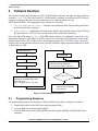
Freescale Semiconductor
Application Note
Document Number: AN2547
Rev. 1, 11/2006
Detecting a CPM Overload on the
PowerQUICC™ II
by
Qiru Zou
NCSD Applications
Freescale Semiconductor, Inc.
Austin, TX
This document describes how to detect a communications
processor module (CPM) overload on MPC8260
PowerQUICC II devices by programming the CPM RISC
timer and the general-purpose timer. A software example
accompanies this document. The method and software
example presented in this application apply to all
PowerQUICC™ II devices.
To estimate the CPM load and to prevent CPM overloads,
use the “MPC8260 CPM Performance Evaluator” tool that is
available for free download on each PowerQUICC II device
web page at the web site listed on the back cover of this
document. Despite your precautions, the CPM can still
become overloaded due to a wrong configuration or a
software bug. The method presented in this document
addresses this possibility and details how to detect CPM
overload in real applications. The method takes advantage of
the fact that the CP RISC timer is a software timer driven by
CPM microcode, while the general-purpose timer is a
hardware timer driven directly by the 60x bus clock or TINx
pin.
To understand this method, you must first understand how
the CPM operates and the structure of the CPM RISC timer
and the general-purpose timer.
© Freescale Semiconductor, Inc., 2003, 2006. All rights reserved.
Contents
CPM Overview . . . . . . . . . . . . . . . . . . . . . . . . . . . . . . .2
RISC Timer . . . . . . . . . . . . . . . . . . . . . . . . . . . . . . . . . 2
General-Purpose Timer . . . . . . . . . . . . . . . . . . . . . . . . .3
Software Example . . . . . . . . . . . . . . . . . . . . . . . . . . . . 4
4.1 Programming Sequence . . . . . . . . . . . . . . . . . . . . .4
4.2 Updates to the FCC ATM Example Software . . . . .5
5 Development Environment . . . . . . . . . . . . . . . . . . . . . .6
6 Testing . . . . . . . . . . . . . . . . . . . . . . . . . . . . . . . . . . . . . .6
7 References . . . . . . . . . . . . . . . . . . . . . . . . . . . . . . . . . . .6
1
2
3
4
CPM Overview
1
CPM Overview
The CPM CP RISC microcontroller (CP) is a 32-bit controller that can perform tasks independently of the
PowerPC core. The CP works with the peripheral controllers and parallel ports to implement
user-programmable protocols and to manage the serial DMA (SDMA) channels that transfer data between
the I/O channels and memory. The CP is a request-driven engine that receives and handles requests from
peripherals from highest priority to lowest priority. Table 14-2 of MPC8260 PowerQUICC™ II Family
Reference Manual shows the order in which the CP handles requests from peripherals according to priority.
As shown in the peripheral prioritization table, the RISC timer is assigned the lowest level and therefore
is the last item in the priority queue (if option 3 of IDMA emulation is not selected).
2
RISC Timer
0
1
Field TIME MCCPR
2
7
1
TIMEP
Reset
R/W
Addr
0X119C4
Reset
2
3
10
11
DR1M DR2M DR1QP
R/W
Field
9
12
EIE
13
SCD
14
2
15
DR2QP
0000_0000_0000_0000
16
1
8
19
ERAM
3
20
21
22
23
24
25
26
27
28
29
30
31
EDM1 EDM2 EDM3 EDM4 DR3M DR4M DR3QP DEM12 DEM34 DR4QP
0000_0000_0000_0000
R/W
R/W
Addr
0X119C6
Reserved on .29μm (HiP3) Rev A.1 and B.3 devices.
Reserved on .29μm devices. See Table 14-3.
ERAM[16-18] and bIt 19 is reserved on .29μm devices.
Figure 1. RISC Controller Configuration Register (RCCR)
The RISC timer is configured using the following registers and data structures:
• RCCR register (Figure 1)—All operations on the RISC timers are based on a fundamental tick of
the CP internal timer that is programmed in the RCCR. The time period of this CP internal tick is
(RCCR[TIMEP] + 1) * 1024 CPM clock cycles. Normally, RISC timer tables are scanned and
updated by microcode during each tick interval.
• RISC Timer Table Parameter RAM—TM_BASE in this parameter table defines the RISC table
base address. If the CP internal timer is enabled (RCCR[TIME] = 1) and the CPM is not
overloaded, the RISC timer internal counter (TM_CNT) is updated by microcode during each tick
interval regardless of whether any of the RISC timers are enabled.
• RISC Timer Table Entries—The 16 timers are located in the block of memory defined by
TM_BASE. All 16 timers are scanned by microcode every tick interval regardless of whether any
are enabled. If any are enabled, microcode updates the RISC timer table entry.
Detecting a CPM Overload on the PowerQUICC™ II, Rev. 1
2
Freescale Semiconductor
General-Purpose Timer
•
•
RTER/RTMR—The RTER is used to report events recognized by the 16 timers and to
generate interrupts. RTMR is the associated mask register.
SET TIMER Command—Enables, disables, and configures the 16 timers in the RISC timer
table. Before issuing the SET TIMER command through the CPCR, you should program
the TM_CMD fields.
For details on RISC timer initialization, consult the MPC8260 PowerQUICC™ II Family
Reference Manual.
As noted earlier, the RISC timer tables have the lowest priority of all CP operations. Therefore, if
the CP is busy with other tasks and does not have time to service the RISC timer during a tick
interval, one or more timers and the RISC timer internal counter (TM_CNT) may not be updated
accurately and therefore run more slowly than expected. This behavior is used to detect a CPM
overload.
3
General-Purpose Timer
The CPM includes four identical 16-bit general-purpose timers or two 32-bit timers (cascade
mode). The general-purpose timer is a hardware timer driven by the bus clock or TINx pin
depended on the setting of TMRx[ICLK]. Therefore, you can use it as the reference timer and
compare it with the RISC timers or TM_CNT to detect whether those software timers are running
slower. To keep the general timer and RISC timer at the same frequency, program one or two of the
general-timers in cascade mode to increase once every CP internal tick, which is (RCCR[TIMEP]
+ 1) * 1024 CPM clock cycles.
To make the general timer (TCNx) increase accordingly, configure the TGCRx and TMRx
properly. Figure 2 shows the clock and prescaler configuration of the general timer. You can
implement three potential clock sources to drive the timer counter: the 60x bus clock directly, the
60x bus clock divided by 16, or the TINx pin in conjunction with an external clock. The prescaler
divides the clock and the resulting frequency drives the timer counter (TCNx).
For details on general-purpose timer configuration, refer to the timers chapter in the MPC8260
PowerQUICC™ II Family Reference Manual.
0
TMRx
7
RRESCALER VALUE
8
9
CE
10
11
12
13 14 15
OM
ORI
FRR ICLK
GE
60x bus clock (CLKIN)
CLKIN/16
Incoming clock/(prescaler value) = count pulse out
TINx Pin
0
15
TCNx
Figure 2. Clock and Prescaler Configuration
Detecting a CPM Overload on the PowerQUICC™ II, Rev. 1
Freescale Semiconductor
3
Software Example
4
Software Example
The software example discussed here uses FCC ATM Example as the base and adds two major functions
from the atm_aalx.c file. The code for the FCC ATM Example is available on each PowerQUICC II device
summary web page at the web site listed on the back cover of this document. Its ID is
MPC8260ADSCOD01. The components of the example are as follows:
1. Init_run_RISC_general_timer()—Initializes and enables the RISC timer and the general timer
to operate at the same frequency.
2. Check_timers()— Samples the real-time values of RISC timer internal counter (TM_CNT) and
the general timer (TCN1||TCN2 in cascade mode), then calculates the difference.
To overload the CPM using atm_aalx.c, ATM CBR channel number 2 is configured to operate at a very
high transmit data rate (1200 Mbps). In CPM overload, you can invoke Check_timers() to see the timer
internal counter (TM_CNT) run more slowly than the general timer (TCN1||TCN2). Figure 3 shows the
software flow for the software detection of an overload, from RISC timer initialization until the overload
is indicated by an LED.
Initialize RISC timer
Overload CPM
Initialize general timer
Sample the difference between
general timer and TM_CNT again
Enable general timer
diff_2= abs (general timer - TM_CNT)
Enable RISC internal timer
Sample the difference between
general timer and RISC timer internal
count (TM_CNT).
diff_1= abs (general timer - TM_CNT)
diff_2 - diff_1 > 5
RISC timer run slower
CPM has been overloaded
Flash red LED
Figure 3. Flow of the Detecting Software
4.1
Programming Sequence
The programming sequence for detecting a CPM overload in this software example is as follows:
1. Establish the pointer to the RISC timer table parameter RAM.
2. Clear the RISC timer table parameter RAM.
3. Clear the RISC timer event register (RTER) and mask register (RTMR) to disable RISC timer
interrupts.
Detecting a CPM Overload on the PowerQUICC™ II, Rev. 1
4
Freescale Semiconductor
Software Example
4. Program the timer global configuration register (TGCR1). General Timers 1 and 2 cascade
to form a 32-bit timer.
5. Program timer mode register (TMR2) to configure timer prescaler value (PS) and to select
the timer input clock source.
In this example, the 60x bus clock divided by 16 is the input clock for general timer, and
the prescaler value is 256. Thus, the cascade timer counter (TCN1||TCN2) increases by one
for every 256 * 16 = 0x1000 60x bus cycles When TGCR1[CAS] = 1, General Times 1 and
2 function as a 32-bit timer. TMR1 is ignored and the modes are defined using TMR2;
erratic behavior may occur if TGCR1 and TGCR2 are not initialized before the TMRs.
6. Clear the cascade timer counter (TCN1 || TCN2).
7. Enable the cascaded general timer through TGCR1[RST2].
8. Program the RISC timer tick by RCCR[TIMEP] and enable the RISC timer by setting
RCCR[TIME]. The RISC timer table is scanned and the RISC timer internal counter
(TM_CNT) is increased by one on each timer tick.
In this example, RCCR[TIMEP] = 7 and the clock ratio of BUS:CPM = 1:2. Thus, a RISC
timer tick is generated on (7 + 1) * 1024 = 0x2000 CPM clock cycles, which is also the
timer period of the general timer counter (0x1000 60x bus cycles).
9. Sample the difference (say diff_1) between the cascade timer counter (TCN1||TCN2) and
the RISC timer internal counter (TM_CNT). diff_1 = abs (TCN1||TCN2 – TM_CNT).
10. Overload the CPM.
11. Sample the difference (say diff_2) between the cascade timer counter (TCN1||TCN2) and
the RISC timer internal counter (TM_CNT) again. Due to a CPM overload at the second
sample point, user can see diff_2 is greater than diff_1.
Steps 1–8 are demonstrated by Init_run_RISC_general_timer() in the atm_aalx.c file. Steps
9 and 11are demonstrated by invoking Check_timers(). For step 10, you can enable the micro
“#define OVERLOAD_CPM” in the fcc_atm.h file. It configures the transmit rate of ATM CBR
channel number 2 to operate at 1200 Mbps, which overdrives ATM pace control and overloads the
CPM.
4.2
Updates to the FCC ATM Example Software
The differences between the current example software and original FCC ATM example software
are as follows:
• The following global declarations and function prototypes are added to the original
atm_aalx.c file:
/* Store the sampled values of difference between general timer and RISC timer
*/
WORD first_sample_point, second_sample_point;
/* The function of sampling the difference between general timer and RISC
timer*/
UWORD Check_timers(void);
/* Initialize and enable RISC timer and general timer to detect CPM overload */
void Init_run_RISC_general_timer(void);
Detecting a CPM Overload on the PowerQUICC™ II, Rev. 1
Freescale Semiconductor
5
Development Environment
/* Disable CPU external interrupt by clearing MSR[EE]*/
void Disable_Exceptions(void);
/* Enable CPU external interrupt by setting MSR[EE]*/
void Enable_Exceptions(void);
•
The following global macro is added to original fcc_atm.h file
/* Enable overload CPM*/
#define OVERLOAD_CPM
For details on the original FCC ATM example software, refer to the 8260_aalx_app.pdf file in this
package.
5
Development Environment
The following development tools were used:
• CodeWarrior™ for Embedded PowerPC version 6.5
• Applied Microsystems WireTap™ probe
• Freescale MPC8260 ADS development board (PILOT version)
• Windows® 2000 platform
6
Testing
All testing used the CodeWarrior debugger environment Version 6.5 and WireTap probe on an
MPC8260ADS development board (PILOT version):
• If #define OVERLOAD_CPM is disabled in the fcc_atm.h file, the CPM is not overloaded.
The Green LED (LD11) should be lighted.
• If #define OVERLOAD_CPM is enabled, the CPM is overloaded. The Red LED (LD12)
should flash.
NOTE
In this testing case, the frequency of BUS/CPM = 66/133 MHz. If
you select a different BUS/CPM ratio, you must modify the
configuration of those two timers accordingly to ensure that the
RISC timer and general timer operate at the same frequency.
7
References
We recommend that you familiarize yourself with the reference materials listed in Table 1, which
are available at the Freescale web site listed on the back cover of this document:
Detecting a CPM Overload on the PowerQUICC™ II, Rev. 1
6
Freescale Semiconductor
References
Table 1. References
Document
Identification Number
MPC8260 PowerQUICC™ II Family Reference Manual:
• Chapter 17, “Timers”
• Section 13.3, “Communications Processor”
• Section 13.6, “RISC Timer Tables”
MPC8260RM
MPC8260 PowerQUICC™ II User’s Manual Errata
MPC8260UMAD
MPC826x Family Device Errata Reference (HiP3)
MPC8260CE
XPC826xA Family Device Errata Reference (HiP4)
XPC8260ACE
Application Note: FCC ATM Example (Works with ENG and PILOT revs of MPC8260ADS) MPC8260ADSCOD01
Detecting a CPM Overload on the PowerQUICC™ II, Rev. 1
Freescale Semiconductor
7
How to Reach Us:
Home Page:
www.freescale.com
email:
[email protected]
USA/Europe or Locations Not Listed:
Freescale Semiconductor
Technical Information Center, CH370
1300 N. Alma School Road
Chandler, Arizona 85224
1-800-521-6274
480-768-2130
[email protected]
Information in this document is provided solely to enable system and software
implementers to use Freescale Semiconductor products. There are no express or
implied copyright licenses granted hereunder to design or fabricate any integrated
circuits or integrated circuits based on the information in this document.
Europe, Middle East, and Africa:
Freescale Halbleiter Deutschland GmbH
Technical Information Center
Schatzbogen 7
81829 Muenchen, Germany
+44 1296 380 456 (English)
+46 8 52200080 (English)
+49 89 92103 559 (German)
+33 1 69 35 48 48 (French)
[email protected]
Freescale Semiconductor reserves the right to make changes without further notice to
Japan:
Freescale Semiconductor Japan Ltd.
Headquarters
ARCO Tower 15F
1-8-1, Shimo-Meguro, Meguro-ku
Tokyo 153-0064, Japan
0120 191014
+81 3 5437 9125
[email protected]
parameters, including “Typicals” must be validated for each customer application by
Asia/Pacific:
Freescale Semiconductor Hong Kong Ltd.
Technical Information Center
2 Dai King Street
Tai Po Industrial Estate,
Tai Po, N.T., Hong Kong
+800 2666 8080
[email protected]
unauthorized application, Buyer shall indemnify and hold Freescale Semiconductor
For Literature Requests Only:
Freescale Semiconductor
Literature Distribution Center
P.O. Box 5405
Denver, Colorado 80217
1-800-441-2447
303-675-2140
Fax: 303-675-2150
LDCForFreescaleSemiconductor
@hibbertgroup.com
Freescale™ and the Freescale logo are trademarks of Freescale Semiconductor, Inc.
The Power Architecture and Power.org word marks and the Power and Power.org
logos and related marks are trademarks and service marks licensed by Power.org. All
other product or service names are the property of their respective owners.
Document Number: AN2547
Rev. 1
11/2006
any products herein. Freescale Semiconductor makes no warranty, representation or
guarantee regarding the suitability of its products for any particular purpose, nor does
Freescale Semiconductor assume any liability arising out of the application or use of
any product or circuit, and specifically disclaims any and all liability, including without
limitation consequential or incidental damages. “Typical” parameters which may be
provided in Freescale Semiconductor data sheets and/or specifications can and do
vary in different applications and actual performance may vary over time. All operating
customer’s technical experts. Freescale Semiconductor does not convey any license
under its patent rights nor the rights of others. Freescale Semiconductor products are
not designed, intended, or authorized for use as components in systems intended for
surgical implant into the body, or other applications intended to support or sustain life,
or for any other application in which the failure of the Freescale Semiconductor product
could create a situation where personal injury or death may occur. Should Buyer
purchase or use Freescale Semiconductor products for any such unintended or
and its officers, employees, subsidiaries, affiliates, and distributors harmless against all
claims, costs, damages, and expenses, and reasonable attorney fees arising out of,
directly or indirectly, any claim of personal injury or death associated with such
unintended or unauthorized use, even if such claim alleges that Freescale
Semiconductor was negligent regarding the design or manufacture of the part.
© Freescale Semiconductor, Inc., 2003, 2006.