1
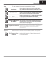
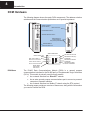
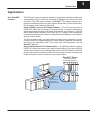
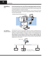
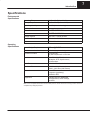
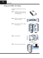
Introduction In This Section. . . . — Overview — DCM Hardware — Applications — Specifications — Using the DCM – Five Steps 1 2 Introduction Overview The Purpose of this Manual This manual is designed to allow you to setup and install your DL405 Data Communications Module (DCM). This is the only manual you will need if you are using the DCM as an extra general purpose communication port for your DL405 PLC system. If you plan on using the DCM as a network master or slave on a DirectNET network, we suggest that you read the DirectNET manual first. The DirectNET manual provides detailed descriptions of network configurations, protocol, and the PLC programs that are necessary to control communications with the DCMs. If you plan on using a personal computer as the network master, it may be helpful to read the DirectNET manual first. In either case, the DirectNET manual can be useful because it provides detailed descriptions of network configurations, various cable connections, etc. Supplemental Manuals Depending on which products you have purchased, there may be other manuals that are necessary or helpful for your application. These are some suggested manuals: User Manuals D DirectNET Network Guide part number DA–DNET–M D DirectSoft Programming Software part number DA–DSOFT–M If you plan to use your D4–DCM to communicate with another PLC, you will need the appropriate user manual for the other PLC. If you plan to use your D4–DCM module as an interface to HMI or PC Control software or to an Operator Interface panel, you will need to refer to the documentation for that product. Who Should Read this Manual If you need an additional communications port for your DL205 PLC and you understand the basics of installing and programming PLCs, this is the right manual for you. This manual gives you the information you need to set up an active port on the D4–DCM module. Quality Technical Manuals and Technical Support We strive to make our manuals the best in the industry. We rely on your feedback to let us know if we are reaching our goal. If you cannot find the solution to your particular application, or, if for any reason you need additional assistance, please call us at 800–633–0405. Our technical support group is glad to work with you in answering your questions. They are available weekdays from 9:00 a.m. to 6:00 p.m. Eastern Time. You can also contact us on the worldwide web at: http://www.plcdirect.com (PLCDirect Web site for general info/file transfers) You can also find a variety of support solutions at our 24–hour per day BBS at: 770–844–4209 If you find a problem with any of our products, services, or manuals, please fill out and return the ’Suggestions’ card that came with this manual. 33 Introduction Steps The main contents of this manual are organized into five steps: 1 Introduction 2 Build the Cable 3 Set the DCM Switches tells you about the Data Communication Module and its uses. It lists other manuals you may need and tells you how to get additional technical assistance, if necessary. guides you through building the necessary communication cable, covering physical and electrical specifications. guides you through the setup of the rotary and DIP switches to select communication parameters and network addressing. It shows the proper method of inserting the module into the base. tells you what to consider when laying out your network 4 Install the DCM and Start cable and how to terminate the individual conductors at the networked devices. It gives you specific cabling examples, the Network 5 introduces the use of the DCM’s status indicator lights as a diagnostic tool. It gives you status indicator light patterns to help you identify problems that could be preventing communications. Appendix A showing pinouts for each device. Verify and Troubleshoot Additional reference information for the D4–DCM is available in this appendix: RLL Communications Programs provides helpful examples of Ladder Logic programs for DCM communications. 4 Introduction DCM Hardware The following diagram shows the major DCM components. The address selection switches and the communication dipswitches are of special importance. Status Indicators (shown below) Base Connector Online/Offline Switch Address Selection Switch DIP Switches for communications and protocol parameters RS232C/RS422 Communication Port Status Indicators Self Test Indicator: ON Module Power: ON NAK: ON if a NAK is either sent or received TOUT: ON if a timeout has occurred in the DCM Send/Receive Enquiry: FLASHING* Send/Receive Header: FLASHING* Send/Receive Data Packet: FLASHING* Master Mode: ON if master OFF if slave DCM Uses The DL405 Data Communications Module (DCM) is a general purpose communications interface for the DL405 family of Programmable Logic Controllers (PLCs). This module is primarily used for three reasons. D As a network interface to a DirectNET network D As an extra general purpose communications port to connect a personal computer or operator interface D As a network interface to a ModbusR network using the RTU protocol The following pages provide an overview of these uses, along with the information you need to connect the DCM. 55 Introduction Applications As a DirectNET Interface The DCM can be used as a network interface for applications that require data to be shared between PLCs, or between PLCs and an intelligent device (such as a host computer). The DCM easily connects to DirectNET. This network allows you to upload or download virtually any type of system data including Timer/Counter data, I/O information, and V-memory information. Using a DCM as part of a PLC Network Master — The DCM can be used in a DL405 PLC station that is serving as a network master. (A master is the network station that initiates requests for data from other stations on the network). The DCM takes communication requests issued from the PLC program and automatically converts these requests into network commands that read data from or write data to another network station. The PLC program is really very simple and only requires a few instructions. You do not have to be a PLC programming guru to use the network. Appendix A provides an overview of the instructions used. (If you want even more information, see the DirectNET Manual). Using a DCM as part of a PLC Network Slave — The DCM can also be used in a DL405 PLC station that is serving as a network slave station. In this case, the DCM “listens” to the network for any messages that contain the DCM’s address. The DCM deciphers the network commands, carries out the request to read or write data, and sends confirmation and/or information to the master station. DirectNET Slaves Slaves respond to the master’s request Communicate with either a PC or DirectNET Slaves 6 Introduction As an Extra Communication Port As an extra communication port, the DCM has specifications similar to the bottom port on the DL405 PLCs. Plus, the DCM can communicate at higher baud rates. If you can connect a device to the bottom port on the DL405 PLC, then you can also connect the same device to the DCM. These devices can be a variety of things, such as operator interfaces or personal computers. Since the DCM does not require any programming, you can simply set the DCM communication parameters, connect the appropriate RS232C or RS422 cables, and start transferring data. Quickly add extra Communication ports* * Number of DCMs is limited by the available power budget As a Modbus Network Interface The DCM can be used as a slave station interface to connect your DL405 system to the Modbus network using the Modbus RTU protocol. The host system must be capable of issuing the Modbus commands to read or write the appropriate data. This manual does not describe the Modbus protocol. You must reference the Gould Modbus Protocol Reference Guide for details (P1-MBUS-300 Rev. B). There may be more recent editions of this manual, so check with your Modbus supplier before ordering the documentation. (A cross reference for the Data Types is supplied later in this manual). Modbus Network using RTU Protocol Network Slave Network Slave DL405 Slave with DCM As a slave station.... responding to network requests 77 Introduction Specifications Environmental Specifications Operating Temperature 32° F to 140° F (0° to 60° C) Storage Temperature –4° F to 158° F (–20° to 80° C) Operating Humidity 5 to 95% (non-condensing) Air Composition No corrosive gases permitted Vibration MIL STD 810C 514.2 Shock MIL STD 810C 516.2 Voltage Isolation 1500 VAC, 1 minute duration Insulation Resistance 10M ohms at 500 VDC Noise NEMA ICS3–304 Power Budget Requirement 500 ma @ 5 VDC Maximum number of modules limited only by power budget Location of module CPU base only any slot except Slot 0 or CPU slot Interface Serial RS232C / RS422 half-duplex, DTE, Asynchronous, 8 bits/character Baud Rates 300 to 38.4K baud, switch selectable Maximum Distance RS232C – 49ft (15 meters) RS422 – 3300 feet (1000 meters) Protocol DirectNET1 K-sequence (proprietary) MODBUS RTU Diagnostics Automatic check of ROM/RAM, communications, switch settings, and LEDs Operating Specifications Note 1: Also compatible with Hostlink and/or CCM2 protocols. These names were used by previous vendors of compatible Koyo designed products. 8 Introduction Using your DCM– Five Steps Complete the following steps to connect the DCM. STEP 1. Familiarize yourself with the communications options of DCM in the Introduction. STEP 2. Build the communication cable that fits your needs. Cable Switches STEP 3. Set the DCM switches. (Baud rate, parity, etc). Install STEP 4. Install the DCM. Verify (Troubleshooting) STEP 5. Verify correct network operation. PWR NAK TOUT MSTR OK ENQ HDR DATA