Transcript
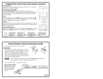
DVS 304 A Digital Video Scaler
The DVS 304 A is a cost-effective, full-featured scaling solution integrated with IP Link® technology. Housed in a 1U full rack, its
primary applications include boardrooms, conference rooms, houses of worship, or any place where multiple displays are installed.
The DVS 304 A incorporates IP Link® technology for control, management, and operation with Ethernet connectivity.
Main Menus and Operation
The DVS 304 A menu system allows the user to navigate menus on the 12 x 2 LCD. The main menu consists of up to nine
submenus:
Installation
•
•
•
•
•
•
•
•
•
1. Turn off power to the DVS 304 A and all other devices that will be connected.
2. If the scaler is to be rack mounted, remove the self-adhesive rubber feet if they have been attached. Refer to the
DVS 304 User's Manual for rack mounting instructions.
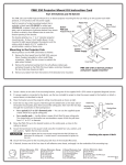
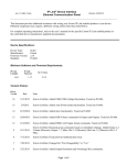
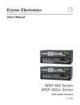
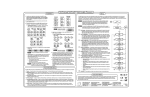
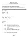
3. Attach the scaler to the input and output devices. See connector diagrams below.
Inputs 1, 2, 3, and 4:
Connect RGB, component video, S-video, or composite video sources to these connectors.
15-pin HD output
Inputs
Input 1: Composite video
SDI input
VID
1
Y
/VID
Y
/VID
H/
HV
Component Video (Y, R-Y, B-Y)
S-video (YC)
B-Y
/C
G
/Y
Outputs
B
/B-Y
RGBS
R
/R-Y
G
/Y
B
/B-Y
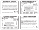
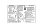
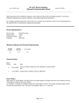
Press the Menu button to move through the menus listed below. From the displayed menu, press the Next button to move
through its submenus. For each submenu, rotate the horizontal ([) and vertical ({) Adjust knobs to make selections.
Refer to the DVS 304 User’s Manual for further information on menus and control buttons on the DVS 304.
RGB/R-Y,Y,B-Y
Input 2: Composite/S-video/component
Composite Video
RGBHV
R
/R-Y
SDI
Y
/VID
B-Y
/C
Input 3: S-video
B-Y
/C
H/
HV
V
R
/R-Y
3
V
Component Video (Y, R-Y, B-Y)
RGsB
G
/Y
B
/B-Y
R
/R-Y
G
/Y
Power
on
B
/B-Y
Input 4: Universal
R-Y
R-Y
2
2
Default Cycle
YC
2 sec.
EXTRON
DVS 304 A
RGB/R-Y, Y, B-Y/YC/VID
2
Start auto image
Input configuration
Picture control
Output configuration
Audio configuration
Memory presets
IP configuration
Advanced configuration
Exit
H/
HV
R-Y
4
V
H/
HV
2 sec.
1
L
L
2
Unbalanced Output
CAUTION
MENU
OUTPUT
CONFIG
6
MENU
INPUT
CONFIG
4
MENU
Tip
Ring
Sleeves
Tip
Ring
7
IP
CONFIG
MENU
MENU
MEMORY
PRESETS
8
ADVANCED
CONFIG
MENU
MENU
9
TO EXIT MENU
PRESS NEXT
NEXT
MENU
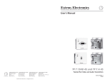
Use the horizontal Adjust knob ([) and the vertical Adjust knob ({) to select the menu options above.
1
Start auto image — Auto imaging allows the selected input to automatically fill the screen using the appropriate size and
centering.
2
Input configuration — The Input Configuration menu allows set up for input 2 (composite video, S-video or component video)
and input 4 (a universal input accepting RGB (RGBcvS, RGBHV, RGBS, RGsB), component video, S-video, and composite video).
This menu also specifies aspect ratio, horizontal/vertical start, total pixels, phase, active pixels, active lines, and film mode.
R
R
NO GROUND HERE
AUDIO
CONFIG
PICTURE
CONTROL
L
L
Sleeves
Tip
5
3
MENU
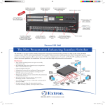
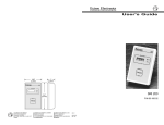
5. For unamplified audio output, connect an audio device to the 3.5 mm, 5-pole captive screw connector using the wiring diagram
below.
NO GROUND HERE
START AUTO
IMAGE ON IN1
Unbalanced Stereo Input
Balanced Stereo Input
Tip
2 sec.
R
R
Tip
Sleeve
2 sec.
OUTPUT
1024 x 768@60
MENU
4. Connect up to four balanced or unbalanced stereo audio input devices to the DVS 304 A. Each audio input has a 3.5 mm,
5-pole captive screw connector. The illustrations below indicate how to wire the connectors for the appropriate audio input type
and impedance.
Tip
Sleeve
2 sec.
INPUT 1
COMPOSITE
V
You can connect both outputs simultaneously to two different displays. The sync format is the same for both outputs.
Tip
Ring
Sleeves
Tip
Ring
60-736-02
FW ver. 1.00
Balanced Output
For unbalanced audio, connect both sleeves to the center contact ground. DO NOT connect the sleeves
to the negative (-) contacts. Do not tin the wires!
6. Plug the scaler, input devices, and output devices into a grounded AC power source.
7. Turn on the input and output devices. Power up the scaler.
8. Use the LCD menu screens to configure the scaler. See “Main Menus and Operation” at right.
3 Picture control — The picture control menu includes all of the picture settings for the scaler including brightness, contrast,
color saturation, tint and detail (sharpness) of the picture, and includes zoom, pan, centering, and sizing.
4
Output configuration — The output configuration menu allows you to select the scaler output rate from different resolution
and refresh rates, sync type, and sync polarity.
Sync polarity can be specified only for RGBHV output.
5
Audio configuration — This menu allows the input level to be adjusted from –15 dB to +9 dB for every audio input. Note that volume
control (0 to 100) is available via SIS™ commands or IR remote control.
6
Memory presets — Allows you to save sizing, centering, and aspect ratio information as presets. There are up to three
presets per input. Input configurations and picture adjustment settings are also stored.
The DVS 304 A front panel contains the following sets of buttons that enable you to control and configure the unit:
7
• Input selection (1- 4) — Select inputs 1 to 4 by pressing the corresponding button. A lit LED indicates the currently
selected input.
IP configuration — IP address of the unit, Subnet and Gateway address can be viewed from the front panel menu. Press
the Input 4 and Next buttons simultaneously for IP address setup.
8
• Menu and Next buttons — Navigate menus on the 12 x 2 LCD by using the Menu and Next buttons. See “Main Menus and
Operation” at right.
Advanced configuration — The advanced configuration menu allows you to configure the global settings, which include
auto image, blue mode, auto switch, RGB delay, test pattern selection, and OSD duration.
9
Exit — Return to the default menu cycle by pressing the Next button, or return to the Start auto image menu by pressing the
Menu button.
Front Panel Buttons
Front Panel Buttons
• Adjustment knobs — Use the horizontal and vertical Adjust knobs to select menu options. See “Main Menus and Operation”
at right.
Executive Mode
To prevent accidental changes to settings, Executive mode locks all panel controls except input control, Preset
Recall/Save, and RS-232 and Ethernet ports. To enable or disable Executive mode, press the Menu and Next buttons
simultaneously, and hold them down for 2 seconds.
Extron Electronics, USA
1230 South Lewis Street
Anaheim, CA 92805
800.633.9876 714.491.1500
FAX 714.491.1517
Extron Electronics, Europe
Beeldschermweg 6C
3821 AH Amersfoort, The Netherlands
+800.3987.6673 +31.33.453.4040
FAX +31.33.453.4050
Extron Electronics, Asia
135 Joo Seng Rd. #04-01
PM Industrial Bldg., Singapore 368363
+800.7339.8766 +65.6383.4400
FAX +65.6383.4664
Extron Electronics, Japan
Kyodo Building, 16 Ichibancho
Chiyoda-ku, Tokyo 102-0082
Japan
+81.3.3511.7655 FAX +81.3.3511.7656
12 06
Rev C
33-1215-02