1
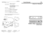
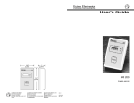
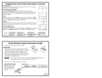
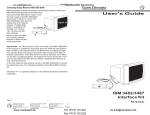
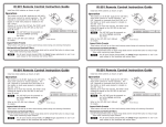
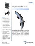
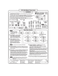
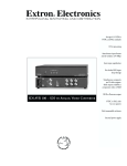
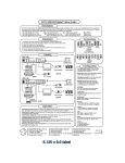
im Vertrieb von
CAMBOARD Electronics
Installation and Operation
User's Guide
Specifications
Input Video Signal
Analog ..... 0.5 to 1.2 volts p-p
ECL ..... 0.8 to 1 volt p-p
Input Sync Signal
..... Sync On Green (RGsB)
..... Composite Sync (RGBS)
..... Separate Horizontal & Vertical (RGBHV)
Output Signal
Video ..... 0.5 to 1 volt p-p
Frequency Compatibility
Horizontal ..... 15-125 kHz
Vertical ..... 30-170 Hz (H & V automatic)
RGB Video Bandwidth ..... 200 MHz (2.1 nS Rise Time)
Power Supply ..... 100-240 VAC 50/60 Hz
..... Internal auto switchable
Dimensions ..... 9.7" W x 7" D x 1.7" H
..... 24.8 cm W x 17.8 cm D x 4.5 cm H
RGB 124 Interface
P/N 60-227-01
Shipping weight ..... 6 lbs. (2.7 kg)
Warranty ..... Two years, parts & labor
Refer to the safety instructions
in the literature that came with
this equipment.
Extron Electronics
1230 South Lewis Street
Anaheim, CA 92805
714-491-1500 FAX 714-491-1517
U.S.A.
Extron Electronics, Europe
Beeldschermweg 6C
3821 AH Amersfoort
+31-33-453-4040 FAX +31-33-453-4050
The Netherlands
www.camboard.de
79-05
Extron Electronics, Asia
68-332-01
41B Kreta Ayer Road
Rev. A
Singapore 089003
+65-226-0015 FAX +65-226-0019
Singapore
Tel. 07131 911201
Fax 07131 911203
[email protected]
im Vertrieb von
Installation and Operation
CAMBOARD Electronics
Installation and Operation
Installation using an MBC cable
Installation using an MBC buffer
1. Use diagram to the right as a guide. Turn off the
computer and its monitor.
2. Disconnect the local Monitor cable from the
computer and connect it to the MBC buffer
connector labeled "Local Monitor" (A).
3. Connect the MBC buffer cable 9-pin connector to
the "Analog/ECL" connector on the RGB 124 (B).
Connect the small plug on the same cable to
"MBC Power Output" on the RGB 124 (B1).
4. Connect the remaining MBC buffer cable to the
computer's video output.
5. Connect RGB 124 Outputs 1 and 2 to output
devices (see Automatic Sync Output below).
6. Apply power to the RGB 124, the CPU and its
monitor, and the output devices.
Operation
RGB 124 operation is covered on Page 2.
1
www.camboard.de
OFF = No power
Dim = Power & no input signal
ON = Power + input signal
Counter-clockwise (CCW) rotation of H CENTER shifts displayed image
to the left, clockwise (CW) rotation shifts displayed image to the right.
CCW rotation
decreases
contrast.
1. Use diagram to the right as a guide. Turn off
the computer and its monitor.
2. Disconnect the local Monitor cable from the
computer and connect it to the MBC cable(A).
3 Connect the MBC cable 9-pin connector to
"Analog/ECL" on the RGB 124 (B).
4. Connect the remaining MBC cable to the
computer's video output (C).
5. Connect RGB 124 Outputs 1 and 2 to output
devices (see Automatic Sync Output below).
6. Apply power to the RGB 124, the CPU and its
monitor, and the output devices.
Tel. 07131 911201
Extron • RGB 124 • User’s Guide
Fax 07131 911203
Extron • RGB 124 • User’s Guide
Automatic Sync Output - Sync output type for both outputs is determined
by the cable connections for output #1 as illustrated below.
CW rotation
increases
contrast.
The Extron RGB 124 is a 200 MHz Dual Output, universal Analog/ECL computer-video
interface designed to connect workstations and PCs to a large screen display system.
With an Extron MBC (monitor breakout cable), the computer’s local monitor may be used
while the RGB/BNC output goes to a large screen. Analog or ECL inputs can be from
VGA, Mac, XGA, XGA-2, Quadra, SUN, SGI, Solbourne, NEC, Siemens, DEC or other
source.
1 = ON = No Sync on Green output
2 = ON = Remove serration pulses
3 = ON = 75 ohms input termination
4 = ON = Always sync negative (-)
5 = ON = LCD sync processing
6 = ON = Always outputs H&V sync
Description
[email protected]
2