1
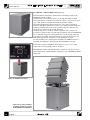
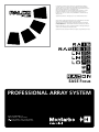
PROFESSIONAL ARRAY SYSTEM
manuale utente | user’s manual
italiano | english
1
user’s manual
I NDEX
1 - AN INTRODUCTION TO "LINE ARRAY" SPEAKER SYSTEMS............42 - 43
1.1 - What makes a lot of stacked speakers boxes a Line-Array.........42
1.2 - Reproduction of low frequencies..................................................43
2 - SYSTEM COMPONENTS.....................................................................44 - 47
2.1 - RA16 - loudspeaker........................................................................44
2.2 - BUMPER - model B1........................................................................45
2.3 - BUMPER LIGHT - model B2.............................................................45
2.4 - RAB1815 - cardioid sub-bass..........................................................46
2.5 - LM24 - digital controller.................................................................47
2.6 - PLM6800 - 'powered controller' 4-channel power amplifier
with digital loudspeaker management ...............................................47
2.7 - EASE FOCUS - Aiming Software....................................................47
3 - RIGGING THE SYSTEM.......................................................................48 - 49
3.1 - Safety standards and regulations.................................................49
3.2 - Safety checks and inspections.......................................................49
4 - SETTING-UP AND ASSEMBLING THE ARRAY....................................50 - 55
5 - SYSTEM WIRING.................................................................................56 - 68
6 - POWER AMPLIFIERS SELECTION........................................................69 - 70
6.1 - PLM6800 - 4-channel power amplifier with digital loudspeaker
management ..........................................................................................70
7 - EASE FOCUS AIMING SOFTWARE.....................................................71 - 72
7.1 - Notes about operating system......................................................71
7.2 - Installation......................................................................................71
7.3 - Program's overview.......................................................................71
8 - PALCOPLUS SYSTEM TECHNICAL DATA............................................73 - 74
APPENDIX.......................................................................................................76
Safety and compliance certification of system's components
english
41
user’s manual
1 - AN INTRODUCTION TO "LINE ARRAY"
SPEAKER SYSTEMS
This document describes the operating principles of the PALCOPLUS
line-array system, as well as its main applications and features.
While not intended to be a complete technical essay about line-array
systems, this chapter will provide a brief summary of the basic theory of
operation and of the benefits of line array systems.
The following chapters will offer a description of the PALCOPLUS system
and its applications, including wiring and flying information.
Understanding the physical principals that determinate the behavior
of these systems will allow the user to optimize its application in mobile
or fixed installations.
The desired result from any sound reinforcement system is high sound
pressure and uniform coverage over the audience area.
This objective has often been addressed by using more powerful speakers, or
a larger number of them.
The problems encountered using this strategy are well known.
Line array systems use a different approach to solve these problems.
1.1 - WHAT MAKES A LOT OF STACKED SPEAKER BOXES A "LINE-ARRAY"?
A
2A
R
2R
Figure 1. Cylindrical wave
A
R
2R
Figure 2. Spherical wave
42
english
4A
The simplest definition of a "line array" is: a number of special independent
units (loudspeakers), vertically stacked and aligned, that operate as a single
sound source and which provide coherent summing, if some conditions
are met.
The vertical stacking achieves a sound field that has a narrow vertical
coverage, with higher directivity and sound pressure than conventional
systems.
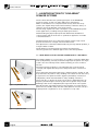
The sound waves emitted are referred as "cylindrical waves" (figure 1), and
they attenuate only 3 dB for every doubling of the distance from the source,
as opposed to the "spherical waves" (figure 2) emitted by conventional
loudspeakers, which attenuate 6 dB for every doubling of distance.
This is true up to a distance from the source which is dependent upon its
frequency and the height of the array, thus the longer the array is made
(building it with more loudspeakers) the longer the throw of the system.
Cylindrical waves only expand in the horizontal plane, not in the vertical
plane. The area doubles every time the radius (distance from the source) is
doubled, which is equivalent to a loss of pressure of only 3 dB.
user’s manual
A
B
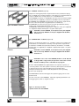
Figure 3. Plane waves: coherent
radiation of multiple wave-guides
Figure 4. Radiation of a curved
array
The loudspeakers ("elements") that make up a "line-array" must meet a
certain set of conditions for the effects to be coherent and acceptable over
a wide frequency range:
1 - The distance between the acoustic centers of the various elements
must be equal to or lower than half the wavelength corresponding to the
maximum frequency to be reproduced.
This means that an array made with small cabinets fitted with small
loudspeakers may be effective to a higher frequency (it is for this reason
that the PALCOPLUS RA16 loudspeaker is fitted with 8" woofers). This is
true for frequencies that are higher than a critical one, that is a function
of the array length. This means that, in order to correctly generate lowfrequency cylindrical waves, the array must be very long.
2 - The separation between the high frequency radiators (wave-guides)
must be minimal: the wave-guides must be tightly spaced. This is the
reason that the array is assembled by tightly coupling the front of the
loudspeakers. The wave-guides must be of special design, because the
sound waves emitted must be time-coherent: they must generate plane
waves. In this way there is no disruptive interference (figure 3 - A) between
radiation from the separate wave-guides: they generate plane waves that
sum coherently (figure 3 - B).
The theoretical line array should be a straight line, but in many cases this
cannot be done, especially when the array must be flown.
A flown, straight array will not give adequate coverage throughout the
audience area and, in practice, it may be necessary to curve the array in
order to achieve sufficient coverage of the nearest areas.
This result in a J-shaped array, where the upper speakers (in a straight line)
are used for the long-throw coverage and the lower speakers, in a curved
line, are used for the short-throw coverage (figure 4).
Each speaker that makes up the line array must incorporate a rigging
system that allows aiming in the vertical plane.
The rigging system, usually an integral part of the units, allows for hinging
at the front of the box so that the separation between the speakers stays
the same, while the rear plates allow for adjusting the angle between
speakers ("splay" angle).
A software program is used to determine the correct angle between the
various speakers of the array. Starting from the geometry of the venue, the
desired coverage and the number of speakers available, this program will
give the correct splay angle between the speakers and the correct rigging
point. For the PALCOPLUS system we supply the custom EASE FOCUS
software.
1.2 - REPRODUCTION OF LOW FREQUENCIES
For the reasons explained above, a line-array's low frequency reproduction
is limited by the array's length (and by it's components).
Special low frequency units are thus used.
To extend the response to the lowest octaves, the PALCOPLUS system
utilizes a specially designed sub-bass unit, model RAB1815.
It's two low frequency woofers, an 18" and a 15", are acoustically loaded
in different ways, while the geometry of the system and the frequency and
phase correction supplied by the LM24 digital controller or by the digital
controller integrated into the PLM6800 'powered controller' transform it
into a directive low-frequency source, with a cardioid directivity pattern.
The RAB1815, due to it's size and weigh, is not intended to be flown.
english
43
user’s manual
2 - SYSTEM COMPONENTS
The PALCOPLUS line array is a system, made up of different components
that must be used together for maximum results:
- RA16 - enclosure
- BUMPER (model B1 or B2)
- RAB1815 - cardioid sub-bass unit
- LM24 - digital controller (with RACon PC software) or, as an alternative,
- PLM6800 'powered controller' 4-channel power amplifier
- LD2.4 - USB interface
- EASE Focus - Aiming Software
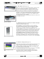
2.1 - RA16 - enclosure (figure 5)
Figure 5. RA16
Figure 6. Integral rigging system
Two-way speaker system, equipped with 2 woofers in a dipole
configuration (8" with 2.5" moving coil, neodymium magnet) and an
HF driver with a 3" titanium diaphragm, neodymium magnet, loaded
by a plane wave guide with 1.4" throat.
The cabinet is built from tough 15 mm Finnish birch with a special coating
providing very high resistance to abrasion; it weights just 18 kg, including
the special steel suspension fittings (figure 6).
For each speaker an external power amplifier is specified, with at least
800 W / 8 ohms for the woofers and 200 W / 16 ohms for the driver.
A two channel amplifier (1600 W / 4 ohm per channel) is suitable for
driving two units.
The frequency range is 70 Hz ÷ 20 kHz, the crossover is at 800 Hz,
24 dB/octave.
Each enclosure is supplied with:
- 2 rear steel plates that allow the assembly of the enclosures in the array
and for adjusting the vertical splay angle between units (figure 7 - A).
- 6 highly resistant quick release pins (figure 7 - B) with ball safety lock
(3/8" x 1/2").
Connection to power amplifiers is by a 4-pole neutrik speakon® socket.
A second socket allows parallel connection of a second speaker (figure 8).
Refer to chapter 5 for wiring details.
Figure 7. Vertical angle
adjustment bars and quick
release pins
Figure 8. RA16 Rear panel
44
english
user’s manual
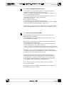
2.2 - BUMPER - model B1 (figure 9)
Figure 9. BUMPER - model B1
Suspension frame (grid) made of high-resistance steel, certified for flying
up to 16 RA16 units and that doubles as lower base for stacked installations
of up to 6 RA16 units on stage surface or on an RAB1815 unit.
If the BUMPER is stacked on an RAB1815, then the user must install suitable
anti-slip feet (not supplied), screwed into the M16 inserts incorporated in
the BUMPER. If the BUMPER is lpositioned on the ground or stage surface,
the use of the anti-slip feet is suggested, but not mandatory.
The BUMPER has several hoisting points, that will give different aiming
angles ("tilt" angles) when the system is flown.
The BUMPER is fitted with 4 fixing plates for 100 mm casters (not supplied).
It is supplied complete with 6 (3/8" x 1") quick release pins.
CAUTION: to fix the BUMPER, use the quick release pins supplied with it exclusively. DO NOT use the pins supplied with the RA16 enclosures !!!
2.3 - BUMPER LIGHT - model B2 (figure 10)
Figure 10. BUMPER LIGHT model B2
Similar to model B1, but lighter. It is certified for flying up to 8 RA16 units
and doubles as a lower base for stacking on the ground or stage surface
a maximum of 4 RA16 units (after the mandatory installation of suitable
anti-slip feet, not supplied). It is supplied complete with 6 (3/8" x 1") quick
release pins.
CAUTION: to fix the BUMPER, use the quick release pins supplied with it exclusively. DO NOT use the pins supplied with the RA16 enclosures !!!
CAUTION: in case of use of the BUMPER (mod. B1 or mod. B2) laid on the ground or stage surface, the position of the center of mass must be verified by means of the EASE Focus program.
Both B1 and B2 BUMPERS are supplied with front suspension plates, for
connecting them to the first speaker of the array. These plates are retained
in their transport position (protected) by two quick release pins.
These pins must be removed to rotate the plates into their operating
position (see chapter 4).
The EASE FOCUS software will suggest the optimal rigging point for the
desired result.
For the correct use of the BUMPERS, especially regarding maximum load
and rigging point, refer to chapters 3 and 4.
Figure 11. An array of 8 RA16
speakers flown from the BUMPER
english
45
user’s manual
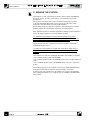
2.4 - RAB1815 - cardioid sub-bass unit (figure 12)
Figure 12. RAB1815
Cardioid sub-bass, designed to extend the low frequency range of the
PALCOPLUS system to 30 Hz.
It employs two low-frequency drivers: an 18-inch (bass-reflex-loaded)
and a 15-inch (horn-loaded), both featuring a 4-inch, long-excursion voice
coil, a dual-spider and a super-ventilated neodymium magnet.
The synergy between the drivers results in a "fast" and accurate bass
response. The drivers' different acoustic loads compensate their frequency
response and extend and correct the system’s response in the very low
range, thus increasing its throw and directivity.
The polar response is "cardioid" within a large band. A conventional
woofer has a response that is practically omni-directional. Instead RAB1815
has a "directive" response, meaning that the acoustic energy is directed
only where it is needed. The reduced emission from the enclosure's rear
helps attenuate the low frequency acoustic feedback on stage.
For each module a two channel power amplifier (2 x 1600 W / 4 ohm) is
specified; this amplifier is driven by the dedicated LM24 controller.
Connection to power amplifiers is by an 8-pole neutrik speakon® socket
(figure 13). For wiring details, refer to chapter 5.
One RAB1815 sub-bass unit may be used as a base for a ground or stage
level stacked array of RA16 speakers, installed on top of BUMPER model B1
(figure 14).
Figure 13. RAB1815 rear panel
Figure 14. An array of 4 RA16
speakers stacked on a model
B1 BUMPER and an RAB1815
46
english
user’s manual
2.5 - LM24 - digital controller (figure 15)
Figure 15. LM24
Thanks to it’s "state-of-the-art" DSP and A/D and D/A converters, this unit
will drive the system’s power amplifiers; operating simultaneously
as a cross-over, equalizer and limiter to optimize the system's response.
It may be used in a free-standing mode, utilizing the front panel's LCD
display and keyboard to operate on factory pre-sets with adjustable
parameters; or it may be controlled by a personal computer that, thanks to
the RACon control software and the LD2.4 USB interface (figure 16), allows
adjustment and configuration of a network of up to 8 LM24 controllers.
For wiring instruction, refer to chapter 5.
For detailed instructions about the LM24 and the RACon PC software, refer
to the LM24 user's manual.
Figura 15b: PLM6800
2.6 - PLM6800 'powered controller' 4-channel power amplifier with digital
loudspeaker management (figure 15 b)
Model PLM6800 is a "powered loudspeaker controller" designed to
be used with the PalcoPlus line-array system. It incorporates a digital
controller (functionally equivalent to the model LM24) and four power
amplifiers, each one capable of delivering up to 1700 W @ 4 ohms.
A single PLM6800 may effortless drive one PALCOPLUS system composed by
two RA16 speakers and one RAB1815 woofer. The system's wiring is made
easy thanks to an 'intelligent' control of the power amps output wiring,
offering a real protection of the system's drivers against wiring errors.
The PLM6800 may be used in free-standing mode by means of the front
panel's LCD display and keyboard, operating on factory pre-sets with
adjustable parameters, or it may be controlled by a personal computer
that, thanks to the RACON control software and the LD2.4 USB interface,
allows adjustment and configuration of a network of up to eight PLM6800.
Figura 16. USB LD2.4 interface
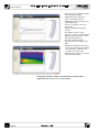
2.7 - EASE Focus - Aiming Software (figure 17)
Figure 17. EASE Focus screen
shot
Dedicated acoustical simulation software: starting from a geometric model
of the actual venue space (geometry of the place, audience position,
number of speakers to be used), it will compute, in an interactive mode,
the array's geometry, calculating the splay angles to be assigned to the
array modules during the array assembly.
It will also indicate the exact position of the hoisting point on the BUMPER,
so that the array will have the correct tilt angle once flown.
For instructions about the software’s installation, refer to chapter 9.
The program includes a complete and detailed on-line help, and we
suggest that the user refer to it for more details.
english
47
user’s manual
3. RIGGING THE SYSTEM
This chapter contains important information about flying a PALCOPLUS
line array system, as well as a description of the elements and safety
precautions.
Our goal is to allow the user to become familiar with the procedures
to be followed while flying the acoustic system, as well as the safety
measures to be taken during set-up and disassembly.
Before performing any operations related to flying the system, read the
present chapter first, and heed the warnings and advice given.
Only experienced persons with the required knowledge of the equipment
and local safety regulations should fly speaker systems.
It is the user’s responsibility to ensure that the systems to be flown
(including flying accessories such as structures, hoists, chains and cables)
comply with applicable government and local regulations.
The working load limits stated in this manual have been certified by
independent laboratories.
It is the user’s responsibility to comply with loads limits, safety factors,
resistance values, periodical checks and all the warnings given in this
manual.
The suspension accessories supplied by Montarbo are suitable for rigging:
• up to 8 RA16 speakers with a B2 BUMPER
• up to 8 RA16 speakers with a B1 BUMPER, when using a single suspension
point
• up to 16 RA16 speakers with a B1 BUMPER, when using two suspension
points.
The loading capacity of the suspension accessories supplied by Montarbo
have been certified by an external structural design consultant.
A partial copy of the certification document is enclosed in the appendix.
The compete document, in it's original form, is available at the Montarbo
main offices.
48
english
user’s manual
3.1 - SAFETY STANDARDS AND REGULATIONS
To this date and to our knowledge, there is no accepted standard or
regulation regarding the flying of acoustic systems.
However, it is common engineering practice to apply 5:1 safety factors
for enclosures and static elements.
For slings and elements exposed to material fatigue due to friction and
load variation, the following ratios must be met:
5:1 for steel cable slings,
4:1 for steel chain slings and
7:1 polyester slings (not allowed in some countries)
Thus, an element such a steel chain, with a breaking load limit of 1000 Kg
may be statically loaded with 250 Kg (4:1 safety factor).
When flying a system, the working load must be lower than the resistance
of each individual flying point in the array, as well as on each enclosure.
3.2 - SAFETY CHECKS AND INSPECTIONS
Hanging hardware should be regularly inspected and suspect units
replaced if there is any doubt.
This is important to avoid injury and damage, and absolutely no risks
should be taken in this respect.
We strongly recommend that an inspection and maintenance program
on flying elements be implemented.
This should be done in a written form and include reports filled out by
the personnel that will carry out the inspections.
In case of accident, local regulations may require you to present evidence
of inspection reports and corrective actions taken after defects were found.
Regulation on hoist and chain maintenance in some countries require
a programmed inspection and maintenance program to be performed by
a Certified Body or by a competent professional.
No risks should be taken with regards to public safety. Absolutely!
When flying enclosures from ceiling support structures, extreme care
should be taken to assure, by calculation and in some cases by actual
measurement, that the load-bearing capabilities of the structures are
not exceeded, so that the installation is absolutely safe.
Do not fly enclosures from unsafe structures. Consult a certified
professional if needed.
All flying accessories that are NOT supplied by Montarbo are the user’s
responsibility. Use at your own risk.
english
49
user’s manual
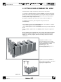
4 - SETTING UP AND ASSEMBLING THE ARRAY
The mechanical set-up of the array is carried out in two phases:
a) assembly of the RA16 speakers and the BUMPER, using the rear rigging
plates (that allow joining the speakers composing the array and adjusting
the splay angle between adjacent speakers) and the quick-release pins,
featuring a ball safety lock (QuickLock).
b) "flying" the system or positioning it on the ground or stage floor.
To simplify the operation, the two phases may be carried out
simultaneously.
The suspension accessories supplied by Montarbo are suitable for rigging:
• up to 8 RA16 speakers with a B2 BUMPER
• up to 8 RA16 speakers with a B1 BUMPER, when using a single suspension
point
• up to 16 RA16 speakers with a B1 BUMPER, when using two suspension
points.
Before beginning the assembly work, the array geometry (the splay angles
between the different RA16 enclosures) must be determined using the
EASE Focus software program, then the following operations must be
carried out:
1) Align on the floor or on a
horizontal plane (e.g. a wooden
board of suitable size and strength)
all the RA16 speakers and the
BUMPER (figure 18.1).
Make sure that their orientation
is correct (top-bottom).
Figure 18.1
2) Make sure that the BUMPER is
placed under the support structure's
rigging point (figure 18.2).
Figure 18.2
50
english
user’s manual
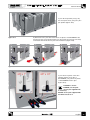
3) Join all the speakers, using only
the front plate holes, using two pins
per speaker (figure 18.3).
Figure 18.3
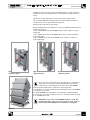
4) Remove the two pins that retain the front plates of the BUMPER in the
transport position. Rotate the plates into the working position (horizontal)
and fasten them with the two pins removed before (figure 18.4).
Figure 18.4
5) Join the front plate of the first
speaker and the front side of
the BUMPER, using the front plates
of the BUMPER and two pins
(figure 18.5).
CAUTION: to fix the BUMPER, use the quick release pins supplied with
it exclusively.
DO NOT use the pins supplied with
the RA16 enclosures !!!
Figure 18.5
english
51
user’s manual
6) Connect the rear side of the BUMPER to the rear of first speaker by
means of 2 plates and 2 pins, using the attachment holes marked for 0°
splay angle (figure 18.6).
CAUTION: to fix the BUMPER, use the quick release pins supplied with it exclusively.
DO NOT use the pins supplied with the RA16 enclosures !!!
Figure 18.6
7) Always verify that the
pins are inserted correctly,
by trying to remove them:
it is mandatory that they cannot
be extracted if the release button
is not pressed (figure 18.7).
Figure 18.7
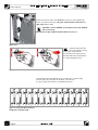
To determine what attachment holes correspond to a certain angle,
refer to figure 19: insert pins in the black colored holes.
A copy of figure 19 is drawn on the RA16 rear panel.
Figure 19. Correspondence between
fixing holes and splay angle
52
english
user’s manual
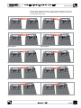
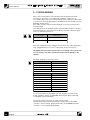
The following images illustrate the correspondence between the holes on
the rear plate and the holes on the RA16 suspension system, as a function
of the desired splay angle.
Splay angle: 0°
Splay angle: 1°
Splay angle: 2°
Splay angle: 3°
Splay angle: 4°
Splay angle: 5°
Splay angle: 6°
Splay angle: 7°
Splay angle: 8°
Splay angle: 9°
english
53
user’s manual
Splay angle: 10°
Splay angle: 11°
Splay angle: 12°
8) Join together the backs of the speakers, starting from the top of the
array: moving from the first to the second, the second with the third,
and so on to the last one, always using 4 pins and 2 plates, and setting
the desired splay angles.
If a splay angle different from 0° is required, after first attaching the
plates to the upper speaker, rotate the lower speaker so that the desired
attachment holes on the plates are aligned with those on the speaker.
The light weight of the speakers allows them to be rotated by holding the
handles of the two adjacent speakers with one hand, as shown in figure 20.
If this procedure turns out to be too difficult or impractical (when the array
is very long or in cases of very marked curvature), it is possible to attach
the BUMPER to the hoist and slowly begin the system rigging, so that the
speakers are at the desired angle (figure 21).
Figure 20
In some cases it may be more practical to assemble blocks of four
loudspeakers, and to fix the first one directly to the rigging structure. After
a partial lift of the structure, other blocks of the array may then be added
(figure 22).
Figure 21
Figure 22
54
english
user’s manual
9) When the whole array has been assembled and still on the ground it is
advisable to attach the speaker cables, as described in chapter 5, before
flying.
10) Once the cables have been connected, the array may be flown.
Follow all the applicable safety precautions (as described in chapter 3),
and be sure to secure safety cables and guy lines.
Check the tilt angle using a clinometer.
Please remember that the suspension accessories supplied by Montarbo are
suitable for rigging:
• up to 8 RA16 units with a B2 BUMPER using a single suspension point
(figure 23)
• up to 8 RA16 units with a B1 BUMPER, when using a single suspension
point (figure 24)
• up to 16 RA16 units with a B1 BUMPER, when using two suspension
points (figure 25).
Figure 23 - BUMPER B2. Single
suspension point
Figure 24 - BUMPER B1. Single
suspension point
Figure 25 - BUMPER B1. Two
suspension points
11) In the case of arrays placed on the stage floor or stacked on a subwoofer, follow the procedures described above, bearing in mind that floor arrays must be inverted and that the BUMPER
must be placed underneath to support the array (figure 26).
It is mandatory to install suitable anti-slip feet when placing a B2 BUMPER
on stage floor or ground.
For the B1 BUMPER, the installation of anti-slip feet is suggested when
positioning it on ground or stage floor, but it is mandatory when stacking
it on an RAB1815 woofer.
CAUTION: in case of use of the BUMPER (mod. B1 or mod. B2) placed on ground or stage surface, the position of the center of mass must be verified by means of the EASE Focus program.
Figure 26
english
55
user’s manual
5 - SYSTEM WIRING
Due to the low impedance of the speakers and the high power levels
involved, it is necessary to use cables with adequate copper section.
For a simpler approach, we recommend the use of 4-conductor cables wired
to neutrik speakon® plugs (type NL-4 for the RA16 enclosures and NL-8 for the
RAB1815 sub-bass units).
Each cable conductor must have the minimum cross section shown in the
following table.
The cables must be of adequate quality, with a flexible insulation, suitable
for the installation's environmental conditions, and with sufficient copper
section to minimize power loss.
Cable length
Cable section
up to 20 meters
2.5 mm2 (AWG 10)
more than 20 meters
4.0 mm2 (AWG 6)
Each pair of RA16 enclosures requires an interconnection cable, 0.5 meters
long, equipped with neutrik speakon® NL-4 plugs, at least 4 x 1.5 mm2.
The high power involved necessitates the correct wiring of the system: any
error in wiring or any cable reversal will result in serious damage to the
speakers.
The array speakers are wired as follows:
Neutrik Speakon® NL- 4 pins
RA16
1+
LF+
1-
LF-
2+
HF+
2-
HF -
Neutrik Speakon® NL- 8 pins
RAB1815
1+
n.c.
1-
n.c.
2+
n.c
2-
n.c.
3+
18" +
3-
18" -
4+
15" +
4-
15" -
(8 ohm)
(16 ohm)
(4 ohm)
(4 ohm)
To connect the mixer to the LM24 controller, and the controller to the
power amplifiers, always use SHEILDED cables (signal cables, balanced),
of adequate section and quality.
The system's wiring is a function of the selected set-up.
The following pages illustrate the wiring corresponding to the LM24
controller's factory Set Up (pages 57-63) and to the PLM6800 powered
controller's factory Set Up (pages 64-68).
56
english
user’s manual
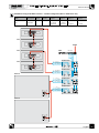
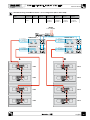
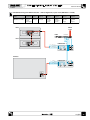
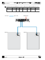
PALCOPLUS wiring with LM24 controller - standard configuration (RA16 + RAB1815 A Flw)
Name
Description
Input A
Input B
Output 1
Output 2
Output 3
Output 4
RA16 + RAB1815 A
Flw
PalcoPlus
Standard
mono
disabled
RA16 HF
(2 couples)
suspended
RA16 LF
(2 couples)
suspended
RAB1815
15"
(1 couple)
RAB1815
18"
(1 couple)
RA16
RA16
MIXER
RA16
LM24
LF+ SPEAKON 1+
LF- SPEAKON 1HF+ SPEAKON 2+
HF- SPEAKON 2-
RA16
4 3 2 1
POWER AMP. 1
- +
A
LF+ SPEAKON 1+
LF- SPEAKON 1HF+ SPEAKON 2+
HF- SPEAKON 2-
RAB1815
A
B
A
B
A
B
A
- +
B
- +
B
POWER AMP. 3
- +
A
1
1
nc
nc
nc
nc
- +
B
POWER AMP. 4
- +
A
- +
B
4
4
2
2
1
1
nc
nc
nc
nc
4
4
3
3
4
4
15”
3
3
18”
4
4
SUBWOOFER SYSTEM
2
2
MADE IN ITALY
Montarbo
18"+ SPEAKON 3+
18"- SPEAKON 315"+ SPEAKON 4+
15"- SPEAKON 4-
A
POWER AMP. 2
- +
18"+ SPEAKON 3+
18"- SPEAKON 315"+ SPEAKON 4+
15"- SPEAKON 4-
B
RAB1815
SUBWOOFER SYSTEM
MADE IN ITALY
Montarbo
15”
18”
english
57
user’s manual
PALCOPLUS wiring with LM24 controller - small configuration (RA16 + RAB1815 A Stk)
Name
Description
Input A
Input B
Output 1
Output 2
Output 3
Output 4
RA16 + RAB1815 A
Stk
PalcoPlus
Reduced
mono
disabled
RA16 HF
(1 couple)
stacked
RA16 LF
(1 couple)
stacked
RAB1815
15"
(single)
RAB1815
18"
(single)
RA16
MIXER
LM24
4 3 2 1
RA16
LF+ SPEAKON 1+
LF- SPEAKON 1HF+ SPEAKON 2+
HF- SPEAKON 2-
POWER AMP. 1
- +
A
B
A
B
A
- +
B
RAB1815
18"+ SPEAKON 3+
18"- SPEAKON 315"+ SPEAKON 4+
15"- SPEAKON 4-
POWER AMP. 2
- +
A
nc
nc
4
4
3
3
4
4
15”
nc
nc
18”
1
1
english
SUBWOOFER SYSTEM
2
2
MADE IN ITALY
Montarbo
58
- +
B
user’s manual
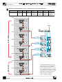
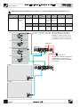
PALCOPLUS wiring with LM24 controller - stereo configuration (RA16 + RA16 A&B)
Name
Description
Input A
Input B
Output 1
Output 2
Output 3
Output 4
RA16 + RA16 A&B
RA16
stereo
L Channel
R Channel
RA16 HF
(2 couples)
suspended - L
RA16 LF
(2 couples)
suspended - L
RA16 HF
(2 couples)
suspended - R
RA16 LF
(2 couples)
suspended - R
MIXER
L - R outputs
LM24
LF+ SPEAKON 1+
LF- SPEAKON 1HF+ SPEAKON 2+
HF- SPEAKON 2-
POWER AMP. 3
B
- +
A
LF+ SPEAKON 1+
LF- SPEAKON 1HF+ SPEAKON 2+
HF- SPEAKON 2-
4 3 2 1 B
A
- +
B
A
B
A
POWER AMP. 1
- +
POWER AMP. 4
- +
LF+ SPEAKON 1+
LF- SPEAKON 1HF+ SPEAKON 2+
HF- SPEAKON 2-
A
LF+ SPEAKON 1+
LF- SPEAKON 1HF+ SPEAKON 2+
HF- SPEAKON 2-
A
B
A
- +
B
POWER AMP. 2
- +
- +
B
L
B
A
- +
B
R
RA16
RA16
RA16
RA16
RA16
RA16
RA16
RA16
english
59
user’s manual
PALCOPLUS wiring with LM24 controller - split RA16 array configuration (RA16 Ch4)
Name
Description
Input A
Input B
Output 1
Output 2
Output 3
RA16 Ch4
RA16
split array
mono
disattivato
RA16 HF
(3 couples)
suspended high
RA16 LF
RA16 HF
(3 couples)
(1 couple)
suspended high suspended low
Output 4
RA16 LF
(1 couple)
suspended low
RA16
RA16
MIXER
LM24
4 3 2 1
LONG THROW
RA16
LF+ SPEAKON 1+
LF- SPEAKON 1HF+ SPEAKON 2+
HF- SPEAKON 2-
RA16
POWER AMP. 1
- +
A
LF+ SPEAKON 1+
LF- SPEAKON 1HF+ SPEAKON 2+
HF- SPEAKON 2-
A
LF+ SPEAKON 1+
LF- SPEAKON 1HF+ SPEAKON 2+
HF- SPEAKON 2-
A
LF+ SPEAKON 1+
LF- SPEAKON 1HF+ SPEAKON 2+
HF- SPEAKON 2-
B
A
B
A
B
A
- +
B
- +
B
POWER AMP. 3
- +
RA16
A
POWER AMP. 2
- +
RA16
B
- +
B
POWER AMP. 4
- +
A
- +
B
NEAR FIELD
RA16
60
english
RA16
This preset is intended to be used
when the venue or the auditorium
is very "deep" and a long-throw
array is required. It allows to control
the "near-field" section of the array
(outputs 3 and 4 of LM24 controller)
with settings different than those
assigned to the "long-throw"
section (outputs 1 and 2).
user’s manual
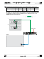
PALCOPLUS wiring with LM24 controller - RAB1815 split (RAB1815 A&B)
Name
Description
Input A
Input B
Output 1
Output 2
Output 3
Output 4
RAB1815 A&B
RAB1815
split array
L Channel
R Channel
RAB1815
15"
R Channel
RAB1815
18"
R Channel
RAB1815
15"
L Channel
RAB1815
18"
L Channel
MIXER
L - R outputs
LM24
18"+ SPEAKON 3+
18"- SPEAKON 315"+ SPEAKON 4+
15"- SPEAKON 4-
4 3 2 1 B
POWER AMP. 2
B
- +
A
18"+ SPEAKON 3+
18"- SPEAKON 315"+ SPEAKON 4+
15"- SPEAKON 4-
A
POWER AMP. 1
B
- +
- +
A
B
L
A
- +
B
R
RAB1815
RAB1815
1
1
nc
nc
3
3
4
2
2
nc
nc
4
4
4
18”
15”
1
1
nc
nc
3
3
4
2
2
nc
nc
4
4
4
MADE IN ITALY
MADE IN ITALY
Montarbo
Montarbo
18”
15”
english
61
user’s manual
PALCOPLUS wiring with LM24 controller - inputs A & B (PalcoPlus in A&B)
Name
Description
Input A
Input B
Output 1
Output 2
Output 3
Output 4
PalcoPlus in A&B
PalcoPlus
Flown
A & B inputs
HF input
LF input
RA16 HF
(2 couples)
Flown
RA16 LF
(2 couples)
Flown
RAB1815
15"
(1 couple)
RAB1815
18"
(1 couple)
RA16
RA16
MIXER
LF HF
RA16
LM24
LF+ SPEAKON 1+
LF- SPEAKON 1HF+ SPEAKON 2+
HF- SPEAKON 2-
RA16
4 3 2 1
POWER AMP. 1
- +
A
LF+ SPEAKON 1+
LF- SPEAKON 1HF+ SPEAKON 2+
HF- SPEAKON 2-
RAB1815
A
A
1
1
nc
nc
nc
nc
4
4
2
2
1
1
nc
nc
nc
nc
4
4
3
3
4
4
15”
3
3
18”
4
4
SUBWOOFER SYSTEM
2
2
MADE IN ITALY
Montarbo
RAB1815
15”
18”
english
SUBWOOFER SYSTEM
MADE IN ITALY
Montarbo
62
B
A
B
A
B
A
- +
B
- +
B
POWER AMP. 3
- +
18"+ SPEAKON 3+
18"- SPEAKON 315"+ SPEAKON 4+
15"- SPEAKON 4-
A
POWER AMP. 2
- +
18"+ SPEAKON 3+
18"- SPEAKON 315"+ SPEAKON 4+
15"- SPEAKON 4-
B
- +
B
POWER AMP. 4
- +
A
- +
B
user’s manual
PALCOPLUS wiring with LM24 controller - small configuration, inputs A & B (MiniPalco+ in A&B)
Name
MiniPalco+ in A&B
Description
Input A
PalcoPlus
HF input
Stacked
A & B inputs
Input B
Output 1
Output 2
Output 3
Output 4
LF input
RA16 HF
(1 couple)
Stacked
RA16 LF
(1 couple)
Stacked
RAB1815
15"
(single)
RAB1815
18"
(single)
RA16
MIXER
LF HF
LM24
4 3 2 1
RA16
LF+ SPEAKON 1+
LF- SPEAKON 1HF+ SPEAKON 2+
HF- SPEAKON 2-
POWER AMP. 1
- +
A
B
A
B
A
- +
B
RAB1815
18"+ SPEAKON 3+
18"- SPEAKON 315"+ SPEAKON 4+
15"- SPEAKON 4-
POWER AMP. 2
- +
A
- +
B
nc
nc
4
4
3
3
4
4
15”
nc
nc
18”
1
1
SUBWOOFER SYSTEM
2
2
MADE IN ITALY
Montarbo
english
63
user’s manual
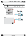
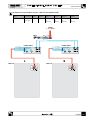
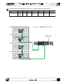
PALCOPLUS wiring with PLM6800 power controller - standard configuration (RA16 + RAB1815 A Flw)
Name
Description PLM6800 n. 1 Input A
RA16 + RAB1815 A Standard
Flw
PalcoPlus
flown
Mono
PLM6800 n. 2 Input A
Mono
RA16
Input B
Ch 1
Disabled
RA16 HF
RA16 LF
RAB1815 no. 1 RAB1815 no. 1
(1 couple) (1 couple) 15"
18"
flown
flown
Input B
Ch 1
Disabled
RA16 HF
RA16 LF
RAB1815 no. 2 RAB1815 no. 2
(1 couple) (1 couple) 15"
18"
flown
flown
Cavo tipo 1
Cavo tipo 2
Type 1 cable
Type 2 cable
Ch 2
Ch 2
Ch 3
Ch 3
Ch 4
Ch 4
This example shows a standard
PalcoPlus system. It is possible to
assemble a reduced system, using
only half of the above components
(1 PLM6800 + 2 RA16 + 1 RAB1815).
RA16
MIXER output
PLM6800 # 1
RA16
Attention!
The InLink configuration parameter
of PLM6800 no. 1 must be set to
LinkOn (default). Refer to PLM6800
user's manual.
RA16
PLM6800 # 2
RAB1815
nc
nc
15”
18”
nc
nc
nc
nc
15”
18”
SUBWOOFER SYSTEM
nc
nc
Montarbo
RAB1815
english
SUBWOOFER SYSTEM
Montarbo
64
user’s manual
PALCOPLUS wiring with PLM6800 power controller - small configuration (RA16 + RAB1815 A Stk)
Name
Description
Input A
Input B
Ch 1
Ch 2
Ch 3
Ch 4
RA16 + RAB1815 A
Stk
PalcoPlus
stacked
Mono
Disabled
RA16 HF
(1 couple)
stacked
RA16 LF
(1 couple)
stacked
RAB1815
15"
RAB1815
18"
This example shows a PalcoPlus system in a small configuration. It is possible to assemble a larger system,
using the double of the above components (2 PLM6800 + 4 RA16 + 2 RAB1815), wiring the second
PLM6800 as described in the preceding page.
Cavo tipo 1
Cavo tipo 2
Type 1 cable
Type 2 cable
RA16
RA16
MIXER output
RAB1815
nc
nc
nc
nc
4
4
3
3
4
4
15”
1
1
18”
2
2
MADE IN ITALY
Montarbo
english
65
user’s manual
PALCOPLUS wiring with PLM6800 power controller - RA16 stereo configuration (RA16 + RA16 A&B)
Name
Description
Input A
Input B
Ch 1
Ch 2
Ch 3
Ch 4
RA16 + RA16 A&B
RA16
(2 couples)
stereo
Ch L
Ch R
RA16 HF
flown - L
RA16 LF
flown - L
RA16 HF
flown - R
RA16 LF
flown - R
Cavo tipo 1
Type 1 cable
MIXER outputs
B
R
66
english
A
L
RA16
RA16
RA16
RA16
user’s manual
PALCOPLUS wiring with PLM6800 power controller - split RA16 configuration (RA16 4Ch in A)
Name
Description
Input A
Input B
Ch 1
Ch 2
Ch 3
Ch 4
RA16 4Ch in A
RA16
(2 couples)
channel A
Mono
Disabled
RA16 HF
(1 couple)
RA16 LF
(1 couple)
RA16 HF
(1 couple)
RA16 LF
(1 couple)
RA16
Cavo tipo 1
Type 1 cable
RA16
MIXER output
RA16
RA16
english
67
user’s manual
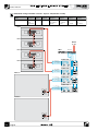
PALCOPLUS wiring with PLM6800 power controller - RAB1815 split configuration (RAB1815 x 2 in A)
Name
Description
Input A
Input B
Ch 1
RAB1815 x 2 in A
RAB1815
split array
Active
Disabled
RAB1815 no. 1 RAB1815 no. 1 RAB1815 no. 2
15"
18"
15"
Cavo tipo 2
Type 2 cable
Ch 2
Ch 3
Ch 4
RAB1815 no. 2
18"
MIXER output
A
RAB1815
RAB1815
SUBWOOFER SYSTEM
68
english
18”
1
1
nc
nc
3
3
4
15”
2
2
nc
nc
4
4
4
1
1
nc
nc
3
3
4
2
2
nc
nc
4
4
4
MADE IN ITALY
MADE IN ITALY
Montarbo
Montarbo
18”
15”
user’s manual
6 - POWER AMPLIFIER SELECTION
When selecting a power amplifier, don't go for "just enough power".
An underpowered amplifier will provide no performance advantages, not
even in terms of reliability (indeed, loudspeakers are more prone to failure
when driven by an underpowered amplifier), and the dynamics of the
whole system may be compromised.
To ensure that a system is operating at top capacity and best expressing its
dynamic, detailed sound image, very powerful amplifiers are required.
The recommended amplifiers for the PALCOPLUS system must have the
following specifications:
Output power at least 1500 W RMS @ 4 ohms
Gain 36 dB
This gain value corresponds to the factory default value for the OutAttn
parameter in the LM24 controller (see chapter 7).
Amplifiers with different gain or input sensitivity values may be used, as
long as the OutAttn value in the controller's configuration is adequately
modified.
Theoretically speaking, the amplifiers used to drive the HF section of the
RA16 enclosures could be of a lower power rating (considering the
8-ohm impedance of two parallel-connected cabinets), but we strongly
suggest employing identical amplifiers for all the system's components.
There are many reasons for this: the system's organization, the wiring and
even the spare parts inventory are thus simplified; plus, there's no need
for a different configuration of some of the controllers.
Other than power rating, there are other amplifier characteristics that are
of primary importance:
- sound quality ("musicality")
- reliability
- small size and weight (this is especially critical in the case of "touring" systems)
In the case of the first and the second characteristics, a good strategy is to
always deal with a reliable, established supplier.
Always keep in mind that a cheap amplifier is more prone to failure, and
a failure of the power amplifier may lead to a serious failure of the system
drivers.
In the case of the third consideration, it is advisable to select switching
amplifiers (class D or similar) with a switching-mode power supply. These
are more compact and weigh less, resulting in smaller and lighter racks.
english
69
user’s manual
Two-ohm operation.
Many professional power amplifiers may operate on very low loads and
some of them are specified for continuous operation on 2-ohm loads.
It would therefore seem possible to employ one of these "low-impedancecapable" amplifiers to drive two parallel-connected RAB1815 subwoofers
(one channel for the two 18", the other for the two 15"), or 4 parallelconnected RA16 enclosures (one channel for the four LF sections, the other
for the four HF sections).
And, although this is certainly possible, it is not recommended for one or
more of the following reasons:
- 2-ohm operation increases the heat generated by output and power
supply stages, reducing the amplifiers' reliability, making them more prone
to catastrophic failures.
- the high current involved calls for a detailed study of the amplifierspeaker wiring, and the wiring will inevitably become more complicated
and complex.
- the failure of one amplifier will result in an "out of service" condition
(a dramatic muting) of twice the number of speakers, and this may
compromise the entire performance in course.
- the dynamic range and the damping factor of an amplifier operating
on a very-low-impedance load are significantly reduced, and this may
compromise the exceptional dynamic and transient response of the
PALCOPLUS system.
6.1 PLM6800 powered controller - 4-channel power amplifier with digital
loudspeaker management
The use of the PLM6800 gives a number of important advantages:
- the internal amplifiers' gain and power have been optimized for the
PALCOPLUS system;
- the small size and weight give a great space saving;
- system wiring is simplified beacuse all the required power connectors
(Speakon® NL4 e NL8) are ready installed on the amplifier's rear panel,
and thus there's no need to fabricate dedicated wiring panels or adapter
cables;
- the 'intelligent' control of the outputs' wiring (the output connectors
are selectively enabled by the digital controller according to the loaded
preset), gives total protection to the speaker's components against wiring
errors.
70
english
user’s manual
7 - EASE Focus AIMING SOFTWARE
This program has been developed by the SDA Company (Software Design
Ahnert GmbH) and the supplied version has been customized for the
PALCOPLUS system, whose acoustical and mechanical parameters are
pre-loaded.
7.1 - NOTES ABOUT OPERATING SYSTEM
The software operates on the Microsoft Windows 2000®,
Windows XP® or Windows VISTA® operating system, with the .NET
Framework version 1.1 redistributable package.
7.2 - INSTALLATION
The software installation may be started automatically, at the end of
the installation process of RACon software, by simply clicking the
Install EASE Focus tab (see chapter 8), or it can be started manually
using the CD supplied with the USB LD 2.4 interface.
EASE Focus requires the Microsoft® ".NET 1.1 " libraries.
If these are not installed on your PC, you can install them by executing
the dotnetfx.exe file present on the supplied CD.
7.3 - PROGRAM OVERVIEW
The purpose of EASE Focus is to provide both the end user, who needs to
set up the array for a show, as well as the developer, with a tool that allows
the easy and quick prediction of the array's performance in a given venue
The software has been developed on the Microsoft® .Net Framework, and
offers ease of use, high performance and portability.
EASE Focus is a software that allows the modeling of acoustic sources, in
particular line arrays, in two dimensions.
It considers the direct field created by the complex addition of the sound
contributions of the individual loudspeakers or array elements.
Based on an intuitive and consistent interface, EASE Focus is designed for
the end user, as well as the R&D engineer.
english
71
user’s manual
- Aiming and color mapping display
- Zoomed rigging display
- Extended report for printing
- Levels over audience areas
- COM and tilt angle calculation for selected pinpoint
- Presets for audience areas and array setup
- English and German language versions
- SPL display in 1/3rd octaves, octaves, 3 octaves, and broadband
- RMS, program (max SPL for short periods) and peak levels
- Flat and A-weighted levels
- Air attenuation according to ISO 9613
- Amplitude shading, that allows to
calculate the attenuation required for the speakers assigned to the coverage of the near areas.
- Optimized SPL calculation routines for interactive aiming.
The program includes a complete and detailed on-line help, and we
suggest that the user refer to it for more details.
72
english
user’s manual
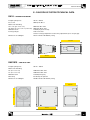
8 - PALCOPLUS SYSTEM TECHNICAL DATA
RA16 - speaker enclosure
Frequency Response
70 Hz ÷ 20 kHz
Cross-over 800 Hz, 24 dB/oct
Max Power Handling
LF: 2 x 8" (2,5" voice coil)
800 watts @ 8 ohms
HF: driver (3" voice coil / 1,4" throat)
200 watts @ 16 ohms
MAX SPL @ 1 m
130 dB (single enclosure)
Coverage Angle
120° Horizontal
Vertical coverage depends from the array adjustment (2 x 6° trap angle)
Dimensions and Weight
W 527 x H 282 x D 440 mm; 18 kg
282 mm.
527 mm.
440 mm.
RAB1815 - sub-bass unit
Frequency Response
30 Hz ÷ 120 Hz
Max Power Handling
18" (4" voice coil)
1600 watts @ 4 ohms
15" (4" voice coil) 1600 watts @ 4 ohms
MAX SPL @ 1m
136 dB (half space)
Directivity Cardioid polar pattern
Dimensions and Weight
W 506 x H 762 x D 748 mm; 58 kg
762 mm.
506 mm.
748 mm.
english
73
user’s manual
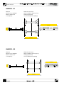
BUMPER - B1
Material
FE360 structural steel
Dimensions and Weight
W 545 x H 90 x D 705 mm; 13 kg
Max allowable load 320 kg (suspended)
Load capacity
max. 16 x RA16 flown (288 kg)
90 mm.
705 mm.
545 mm.
BUMPER - B2
Material
FE360 structural steel
Dimensions and Weight
W 545 x H 90 x D 513 mm; 8,5 kg
Max allowable load 320 kg (suspended)
Load capacity
max. 8 x RA16 flown (144 kg)
90 mm.
513 mm.
545 mm.
74
english
user’s manual
Waste from Electrical and Electronic Equipment
Attention !
The crossed out wheeled bin symbol that can be found on this product means that the product is
covered by the Waste from Electrical and Electronic Equipment Directive. The symbol is intended
to indicate that waste from electrical and electronic equipment must be subject to a selective
collection.
For more details on available collection facilities please contact your local government office or
the retailer where you purchased this product.
The solid bar underneath indicates that the product has been put on the market after 13th
August 2005.
INFORMATION ON PROPER DISPOSAL
Information on Disposal for Users (private households)
In the European Union
Attention: If you want to dispose of this equipment, please do not use the ordinary dust bin!
Used electrical and electronic equipment should not be disposed of via the normal household
waste stream but must be treated separately and in accordance with legislation that requires
proper treatment, recovery and recycling of used electrical and electronic equipment.
Following the implementation by member states, private households within the EU states may
return their used electrical and electronic equipment to designated collection facilities free of
charge*. In some countries* your local retailer may also take back your old product free of
charge if you purchase a similar new one. * Please contact your local authority for further details.
In other Countries outside the EU: If you wish to dispose of this product, please contact
your local authorities and ask for the correct method of disposal.
In Switzerland: Used electrical or electronic equipment can be returned free of charge to the
dealer, even if you don’t purchase a new product. Further collection facilities are listed on the
homepage of www.swico.ch or www.sens.ch.
Information on Disposal for Professional Users
In the European Union
If the product is used for business purposes and you want to discard it: please contact your
Montarbo dealer who will inform you about the take-back of the product. You might be charged
for the costs arising from take-back and recycling. Small products (and small amounts) might be
taken back by your local collection facilities.
In Spain: Please contact the established collection system or your local authority for takeback of
your used products.
In other Countries outside the EU: please contact your local authorities and ask for the correct
method of disposal.
english
75
manuale utente
APPENDI X
Certificazione di sicurezza dei componenti
Safety and compliance certification of system's components
ELETTRONICA MONTARBO S.r.l.
Via G. Di Vittorio n° 13
40057 Cadriano di Granarolo (BO)
Oggetto:
CALCOLO DELLA PORTATA DEGLI ELEMENTI DI
CONNESSIONE MONTARBO IN MICROFUSIONE,
ABBINATI A BUMPER E BUMPER PICCOLO
Calcolatore delle strutture: Dott. Ing. FRANCO FAGGIOTTO
Timbro e Firma
Data: Forlì 04 Dicembre 2008
Dott. Ing. Franco Faggiotto – Via G. Regnoli n. 10 47100 Forlì
Telefono 0543 34961 – Fax 0543 21224 - Cell. 348 3531928
76
italiano
Le informazioni contenute in questo manuale sono state attentamente redatte e
controllate. Tuttavia non si assume alcuna responsabilità per eventuali inesattezze.
Questo manuale non può contenere una risposta a tutti i singoli problemi che possono
presentarsi durante l'installazione e l'uso dell'apparecchio.
Siamo a vostra disposizione per fornirvi eventuali ulteriori informazioni e consigli.
La Elettronica Montarbo srl non può essere ritenuta responsabile per danni o
incidenti a cose o persone, causati o connessi all’utilizzazione o malfunzionamento
dell’apparecchio.
Caratteristiche, dati tecnici e immagini possono essere modificati senza preavviso.
The information contained in this manual have been carefully drawn up and checked.
However no responsibility will be assumed for any incorrectness.
This manual cannot cover all the possible contingencies which may arise during the
product installation and use. Should further information be desired, please contact us
or our local distributor.
Elettronica Montarbo srl can not be considered responsible for damages which may be
caused to people and things when using this product
Specifications, features and pictorial material are subject to change without prior notice.
EASE Focus
PROFESSIONAL ARRAY SYSTEM
Elettronica Montarbo srl
40057 Cadriano - Bologna (Italy)
+39 051 766437 • Fax +39 051 765226
[email protected] • www.montarbo.com


![[en] owner`s manual](http://vs1.manualzilla.com/store/data/006162832_1-909017f8e41cb525dbc302a6f278af8f-150x150.png)