1
ServersCheck
BTS Monitoring Appliance – Quick Overview
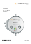
This document is intended to make you familiar with the ServersCheck BTS Monitoring Appliance
Although it is possible, we highly recommend not to install other software on the device as it might
interfere with the Monitoring Software the device was designed for. Installing other software will
void the warranty and support for the device.
1. About the BTS Monitoring Appliance
The ServersCheck Monitoring Software requires a Windows based system to run on. With the
appliance customers get a custom built similar to a PC. Everything is preinstalled so that customers
don’t have to worry about drivers to download, installs or even compatibility issues.
1.1 XPEmbedded
The device runs on XPEmbedded. XPEmbedded (XPe) is a special version of the traditional XP
Professional Operating System that most people are familiar with. XPe is tuned to match
requirements of the system it is designed for so that the ServersCheck software & hardware can run
on this device in the best possible conditions.
XPe has also a much smaller footprint compared to traditional XP versions making it suitable to run on
smaller devices such as the ServersCheck Monitoring Appliance.
By default the appliance is set to following administrator username and password:
Username: Administrator
Password: serverscheck
1.2 Monitoring Software
The version of the ServersCheck Monitoring Software loaded onto the device is the Business 100
Edition. Not only the Operating System but also the monitoring software has been optimized for the
appliance.
License files required for the software to run are preinstalled. A license file is linked to the version it
was issued for. If you want to upgrade the appliance to a higher version, then you need to obtain a
new license file. You can request this from following url:
http://www.serverscheck.com/helpdesk
If you do not yet have a helpdesk account, then following the link to request one. One will be issued
by the next business day or even sooner.
This guide covers the basic installation and features of the appliance. Fine tuning settings, adding
monitors, alerting capabilities, environmental monitoring and other information is available from our
online user manual (wiki) at:
http://wiki.serverscheck.com
The Monitoring Software runs as a service on the appliance. This means that a user does not have to
be logged on to the system to use it and that it is automatically started whenever the appliance is
(re)booted.
Printed June 3, 2010
- Rev 2.1 – PART DOC-MANUAL-APPLIANCE
1
1.3 Other preinstalled software
Next to the Monitoring Software, the following software is installed on the device:
Firefox 3 as web browser (no Internet Explorer on board)
Drivers for Huawei E1552, E169 & E180 modems
Drivers for USB ServersCheck environmental sensors
Drivers for ServersCheck Signal Tower
Drivers for LCD Display (Crystalfontz 634 USB)
.NET 1.1 Framework for ServersCheck’s environmental sensors & security appliance
By having all drivers preinstalled, the user of the appliance does normally not have to look for
compatible drivers for the hardware purchased from ServersCheck (hardware available at the time of
purchase). Hardware released by ServersCheck after the purchase of the appliance may require
additional drivers which are then made available to the user of the appliance through a special url
linked from in the online wiki at http://wiki.serverscheck.com
By default the Windows Firewall is enabled and blocks all inbound connections including those on
port 1272. You need to disable the Windows Firewall or allow incoming connections on port 1272
(see further in this document)
1.4 BTS check types
In this document we will not focus on the different BTS check types supported by the appliance.
Instructions on configuring can be obtained from the main documentation website:
http://wiki.serverscheck.com (under the section of Monitoring Software)
Printed June 3, 2010
- Rev 2.1 – PART DOC-MANUAL-APPLIANCE
2
Visual Product Tour
The front part of the appliance consists of following (from left to right):
Blue led display indicating if appliance is running or not
Yellow led display for disk I/O activity – SSD enabled appliances have no led shown
Gray power button – when running and pressed, it will initiate a shut down cycle. Press for 4
seconds and power will be interrupted (which may cause hard disk damage)
USB port to connect modem for end-user simulation
Printed June 3, 2010
- Rev 2.1 – PART DOC-MANUAL-APPLIANCE
3
The rear consists of following (from left to right):
Plug for power adapter and main power switch under it (under DC-IN 5V label)
PS2 port for Keyboard
PS2 port for mouse
USB Port for second modem with SIM of competitor’s network – this is the alerting modem
RJ45 port for Ethernet cable (10/100)
VGA cable to connect screen
Sensor 1 RS232 for connecting first sensor (temperature & humidity or flooding)
Sensor 2 RS232 for connecting second sensor, security bus or fuel level sensor
When starting up the device, you first need to power through the back button (the dot side of the
button pushed in) and then click on the power button on the front.
Printed June 3, 2010
- Rev 2.1 – PART DOC-MANUAL-APPLIANCE
4
2. Getting Started
2.1. Connecting to the appliance
By default the appliance gets its IP address from the DHCP server in your network. Check on your
DHCP server which IP address was attributed to the appliance. The appliance’s name broadcasted to
the DHCP server is: SERVERSCHECK-AP
If you don’t have a DHCP server or if you want to set the IP address manually then you need to do
exactly the same as for setting an IP address on a normal XP machine. See section 4 on how to
connect to the appliance.
2.2. Accessing the ServersCheck Monitoring Software
The ServersCheck Monitoring Software is a browser and sms based software. For the SMS feature a
GSM modem is required (best connected to the USB port on the back of the appliance). See the
Falcom Samba Quick Install Guide on wiki.serverscheck.com for configuring the GSM modem.
To connect to the appliance, open a browser on your pc and point it to the IP address of the appliance
followed by :1272 as the software runs on port 1272. By default the Windows Firewall is enabled
and blocks all inbound connections including those on port 1272. You need to disable the Windows
Firewall or allow incoming connections on port 1272 (see further in this document)
In the example below the IP address of the appliance is 10.0.0.58
You will be prompted for a username and password once a connection is made to the ServersCheck
web server.
Default settings for the Monitoring Software are:
Username: demo
Password: demo
TIP: username and password are case sensitive. If the web server still does not authenticate then logon
locally to the server using the preinstalled Firefox browser. By default it will open the url
http://localhost:1272. When the webserver is accessed locally, then no credentials are required.
The explanation of the configuration as outlined next is done assuming that your ServersCheck
installation is in English.
Let’s start by performing a first time configuration of the software to set the alerting options.
Printed June 3, 2010
- Rev 2.1 – PART DOC-MANUAL-APPLIANCE
5
Click on Start configuration wizard
Click on the Start Configuration button
After clicking that button it might take a few moments as ServersCheck will try to verify if it can send
out emails on port 25. Many ISP’s block port 25 to outside mail servers and only allow them to use
their own SMTP server (typically in the format of relay.isp.com).
We are now going to submit our email address so that the software can verify if it can use its built-in
mail server.
Printed June 3, 2010
- Rev 2.1 – PART DOC-MANUAL-APPLIANCE
6
If the test fails or if you do not receive the test email then you need to manually configure to the
outgoing mail server. See later in this document on how to set this.
Click on Set Security This brings us to the page where we can change the default username and
password to access the software. Set it to match your preference.
The configuration wizard is now complete. Click on the Go to main screen hyperlink
You will now be shown the Device View which is the default screen of the appliance. If you just use
the appliance for environmental monitoring, then click on All Monitors View
To modify some of the general settings you made earlier, simply click on Configuration and then on
General Settings In the General settings you can also customize the layout of alerts to match your
requirements.
Printed June 3, 2010
- Rev 2.1 – PART DOC-MANUAL-APPLIANCE
7
3.3. Email Alert Settings
Click on Email Settings to modify the email alerts. Best is to set the software use the same outgoing
mail server as you use for your mail client. In smaller organizations this is typically something like
relay.myisp.com
The body of the email alerts can be customized so that you can add custom text into it, modify the
subject or whom it is sent from. If your outgoing mail server requires authentication, then make sure
to set it as well.
Alternatively the system can also use its built-in mail server to send email alerts. Make sure to test it
so that are sure that your network and ISP allow software to send email messages directly out to
target mail servers. ISP’s tend to block this to avoid that bots or similar can send out spam through
their network.
2.4. SMS Alert Settings
See the Falcom SAMBA Quick Install Guide on http://wiki.serverscheck.com for configuring the SMS
alert settings using the Falcom SAMBA GSM Modem.
Printed June 3, 2010
- Rev 2.1 – PART DOC-MANUAL-APPLIANCE
8
When connecting the GSM modem for the first time, you might get an error message stating that the
usbser.sys can’t be found. Click on the Browse button and point to the
c:\Windows\System32\drivers directory
3. Administrating the appliance
As mentioned previously in this guide, the appliance runs on Windows XPembedded, part of the XP
product family. XPe is a special version of XP that is supported by Microsoft for special appliances
like the one you have.
It is administrated in the same way as any other XP based PC. You can connect to the appliance in 2
ways:
1/ connecting a monitor, keyboard and mouse to the appliance and use it like a normal PC
2/ creating a remote desktop connection to the appliance
3.1. Connecting to the appliance as a normal server
On the back of the appliance you can connect a monitor using a standard VGA cable, a PS2 keyboard
and a mouse. If you don’t have a PS2 keyboard then you can also use an USB keyboard using the USB
port on the front. When connected you will be prompted with a standard windows login screen as
shown below.
Printed June 3, 2010
- Rev 2.1 – PART DOC-MANUAL-APPLIANCE
9
By default the administrator username & password are:
Username: Administrator
Password: serverscheck
Click on OK to log in
3.2. Enabling Windows Firewall to allow inbound connections on port 1272
Go to your control panel and open up the Windows Firewall tool by double clicking on the icon.
Click on the Exceptions tab and then on the Add Port button
Printed June 3, 2010
- Rev 2.1 – PART DOC-MANUAL-APPLIANCE
10
3.3. Creating a RDP (Remote Desktop) Connection to the Appliance
To start RDP on a Windows XP based system go to Start > All Programs > Accessories >
Communications > Remote Desktop Connection
A window similar to the following will open. Type the IP address of the appliance and click on
Connect
When using SP3 of XP then you might get following screen. Simply check the box as shown and click
on Connect
The desktop of the appliance will be loaded and you will be prompted for a username and password
Printed June 3, 2010
- Rev 2.1 – PART DOC-MANUAL-APPLIANCE
11
By default the administrator username & password are:
Username: Administrator
Password: serverscheck
Click on OK to log in
TIP: No English keyboard users should be aware that the appliance is set to accept QWERTY keyboard.
If you use a different layout (ie AZERTY, QWERTZ or other), then you need to type as if it is QWERTY.
For example for an AZERTY user you need to press Q for letter A. See QWERTY layout below:
When logged in, you will then be shown with a standard XP desktop where you have full
administrator rights to. You can make it join your company’s network, modify the IP or tune some
settings as per your corporate policy.
When you log in you may experience an HDeck.exe error. This is normal and is due to the fact that
the HDeck software is not designed for running in RDP mode. You may safely ignore this message.
Printed June 3, 2010
- Rev 2.1 – PART DOC-MANUAL-APPLIANCE
12
4. Connecting Peripheral Hardware
ServersCheck’s BTS Monitoring solution has the Monitoring Appliance as central unit. Around this
unit, peripheral hardware can be attached. That hardware can be network based whereby the
appliance communicates over TCP/IP with the peripheral hardware or it can be serial based; in that
event the appliance communicates via serial com with the device that is directly connected to the
appliance.
4.1. Network Enabled Hardware
ServersCheck currently supports 2 different types of network based hardware:
a) PDU’s for performing power shutdowns of devices (put after the rectifier)
b) Cameras for monitoring physical security and O&M activities – ServersCheck supports Axis
network camera’s 209FD or higher
In order to enable the BTS Monitoring Appliance to communicate with the peripheral hardware, a
local network is required. The communication is over TCP/IP.
If a BTS or communication room doesn’t have a network, then ServersCheck recommends the Moxa
EDS-P308 ( http://www.moxa.com/Product/EDS-P308.htm ). Those switches are DIN rail mountable
and offer PoE (required for the Axis network camera’s).
As shown in the above picture, a RJ45 cable is connected from the appliance to the switch. Same
goes for the PDU and camera. For the camera make sure to plug it into of the switche’s PoE ports.
If there is an existing network available in the shelter then the PoE switch would be replaced with the
switch or router currently available. In the event that not enough ports are available, then additional
ports can be created by adding the above PoE switch.
Some shelters have installed equipment that is network enabled. By hooking that equipment to the
same network the BTS Monitoring Appliance is connected to, ServersCheck can monitor those
devices. This would require the monitored devices to support any of the check types available in the
monitoring software on the BTS Monitoring Appliance.
Printed June 3, 2010
- Rev 2.1 – PART DOC-MANUAL-APPLIANCE
13
4.2. Serial Enabled Hardware
ServersCheck supports following serial based hardware:
Temperature & humidity sensor
Security bus for connecting dry contact sensors (smoke, door, glass break, airflow)
Flooding sensor
Fuel level sensor
The BTS Monitoring Appliance has 2 RS232 ports on its back for connecting sensors to it. This means
that out of the box, ServersCheck can support a maximum of 2 sensors connected to it.
In the event that more sensors are required, then we recommend using PoE enabled device servers
such as the IOLAN STS4 D Terminal Server from Perle (http://www.perle.com/products/4-portTerminal-Server.shtml). The PoE enabled version of this device server allows for adding up to 4
additional serial based sensors to the BTS Monitoring Appliance. The device server is IP based
which means that the BTS Monitoring Appliance will communicate over TCP/IP with the device server
through an available switch. Such a device will create so called virtual COM ports on the appliances
that are COM ports but where communication is automatically redirected over TCP/IP.
4.3. Crossover cable trick
If only one networked peripheral has to be connected to the BTS Monitoring Appliance, then the
“crossover cable” trick can be used. This avoids needing to have a switch.
An Ethernet crossover cable is a type of Ethernet cable used to connect computing devices together
directly where they would normally be connected via a network switch, hub or router, such as directly
connecting two personal computers via their network adapters. More info on crossover cables can
be found here: http://en.wikipedia.org/wiki/Ethernet_crossover_cable
To setup a crossover network proceed as follows on the appliance first. Start on the appliance by
launching the Network properties. For that go to Start>Settings>Network Connections
Printed June 3, 2010
- Rev 2.1 – PART DOC-MANUAL-APPLIANCE
14
Double click on the Local Area Connection and then click on Properties
In the next window set an IP address for the appliance. Make sure to leave Gateway and DNS empty
as this is a machine to machine connection over a crossed RJ45 network cable
Now make sure to add the peripheral hardware device in the same network segment. For example
you could give it 10.0.0.31 as an IP address where 10.0.0.32 is the IP address of the appliance.
You have now created a small network between 2 devices without having a switch in the middle.
Printed June 3, 2010
- Rev 2.1 – PART DOC-MANUAL-APPLIANCE
15