1
The Mark of the Professional...
VI. SPEAKER INSTALLATION
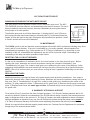
The D-500A is designed to be connected to 4 ohm or 8 ohm speakers directly, or to variable impedance speakers
that match the amplifier’s line output voltage of 25V or 70.7V speaker lines.
CONNECTING FOR DIRECT 4, or 8 OHM OPERATION
Connect 4-ohm speaker(s) to terminals 1 (-) and 2 (+), or 8-ohm speaker(s) to 1 (-) and 3 (+). For proper signal
phasing, observe +/- polarity. NOTE: This is a bridged output. Do not ground either of these terminals.
CONNECTING FOR 25V or 70.7V LINE OPERATION
For 25V output, connect the load to terminals 1 (-) and 4 (+). For 70.7V output, connect the load to terminals 1 (-)
and 5 (+).
NOTE: When using the amp’s 25V or 70.7V line operation, the proper tap setting of the impedance matching
transformer determines the individual speaker’s power level. Using these transformers allows the speakers to be
placed at longer distances from the amplifier without significant power loss. The number of speakers for a linedriven central amplifier system is limited to the power available from the amplifier. The sum of all connected
speakers’ power settings must not exceed 80% of the total power available from the amplifier.
USING THE PROPER WIRE SIZE AND LENGTH
Cable distance should be kept as short as possible to minimize power loss. The chart below can be used as a
general guide showing various wire sizes and the maximum distance related to cable loading that speakers can
be placed from the unit for an approximate -0.5dB loss (-12.5% power). To allow for future expansion and
distributed cable line loss, it is recommended the total system wattage should not exceed 80% of the amplifier’s
rated output. To determine the total system wattage, sum the wattage tap of all speaker(s)/horn(s) used.
2 WIRE COPPER CABLE LENGTHS FOR SPEAKER LINES AT -0.5dB LOSS IN SPL (12.5% POWER LOSS IN WATTS)
AWG
SIZE
4 OHMS 8 OHMS
10
12
14
16
18
20
22
70.7V SPEAKER LINE
(FOR 25V LINE DIVIDE ALL 70.7V LENGTHS BY 8)
NOMINAL POWER IN LOAD
LOW IMPEDANCE
SPEAKER LINE
16
7.5W
15W
30W
60W
100W
125W
250W
400W
500W
120
75
50
30
20
15
240
150
95
60
40
25
480
300
190
120
75
50
10
15
30
7,600
4,800
3,000
1,920
1,200
6,200
3,800
2,400
1,500
960
600
5,000
3,100
1,900
1,200
750
480
300
2,500
1,550
950
600
375
240
150
1,500
940
600
370
230
150
95
1,100
750
450
290
180
110
-
550
375
225
145
90
-
365
230
140
90
-
275
185
110
-
WIRE LENGTHS IN FEET
VII. USING HORN SPEAKERS
ENABLING THE LOW CUT FILTER
If horn speakers are being used, the low cut filter must be activated to protect them. To enable the low cut circuit,
follow these steps. 1) On the same board as the VOX-Mute, look for a tagged jumper that reads, “To activate low
cut filter, cut this jumper.” 2) Cut the jumper and make sure the jumper halves do not touch any of the other part
of the board. The low-cut filter begins to roll off frequencies at 120Hz. NOTE: For complete protection of
compression drivers, or horn diaphrams additional electronic equipment may be necessary.
-5NEW TECHNOLOGY
J.W. Davis & Company
OLD RELIABILITY
• 3030 Canton Street • P.O. Box 710219 • Dallas, Texas 75371-0219
Sales 800-527-5705 • Fax 800-388-9106 • Corp 214-651-7341 • Fax 214-939-0328 • [email protected] • www.jwd.com