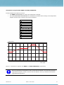
1
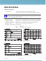
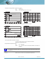
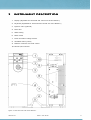
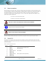
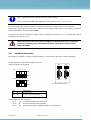
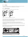
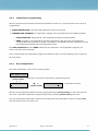
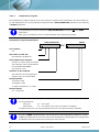
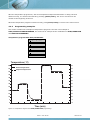
MISTRAL™ USER MANUAL MISTRAL™ temperature calibration values: Calibration 10°C: . °C Calibration 30°C: . °C Calibration 90°C: . °C Serial no Date: Paraph: July 2005 Version 2.5 (0060.063-25) SPARK HOLLAND B.V. SPARK HOLLAND INC. P.O. BOX 388 666 PLAINSBORO ROAD 7800 AJ EMMEN SUITE 1336 THE NETHERLANDS PLAINSBORO, NJ 08536 USA PHONE (31) 591 631700 PHONE (1) 609-799-7250 FAX (31) 591 630035 FAX (1) 609-799-8250 E-MAIL: [email protected] E-MAIL : [email protected] WWW.SPARKHOLLAND.COM Other products by Spark Holland B.V.: • BasicMarathon™ Autosampler • Marathon-XT™ Autosampler • Midas™ Autosampler • Triathlon™ Autosampler • Endurance™ Autosampler • Reliance™ Autosampler • Symbiosis™ • Symbiosis Pharma™ Copyright 2005 Spark Holland BV All rights reserved. No part of this publication may be reproduced, stored in a retrieval system or transmitted in any form by any means, without written permission from Spark Holland BV. Spark Holland BV reserves the right to make changes to the design and specifications of the Mistral™ and this manual without prior notice. DECLARATION OF CONFORMITY We Spark Holland BV, Pieter de Keyserstraat 8, NL-7825 VE Emmen. Declare that the product: Columnthermostat “Mistral™” type 880 is in conformity with the following documents: • EEC directives 89/392 incl. 91/368 and 93/44 (machine safety) and EEC directives 73/23 and 93/68 (low voltage safety), applied with the following standard: EN 61010-1 Safety requirements for laboratory equipment (Class I, Installation cat. II, Pollution degree II) Spark Holland will not accept any liability for damages directly or indirectly caused by connecting this instrument to devices, which do not meet relevant WARNING • safety standards. EEC directives 89/336, 92/31 and 93/68 (EMC requirements), applied with the following standards: EN 61326-1(1997) EMC requirements for electrical equipment and A1(1998) for measurement, control and laboratory use Use shielded cables and connectors for all remote connections. Emmen, May 2002 0060.063-25 Rein van den Berg, QA manager. Mistral™ User Manual 3 2 Mistral™ User Manual 0060.063-25 TABLE OF CONTENTS SPECIFICATIONS 5 1 INTRODUCTION 9 2 INSTRUMENT DESCRIPTION 11 3 INSTALLATION 13 4 3.1 Unpacking 13 3.2 Power connections 14 3.3 Control I/O 14 3.4 MultiLink Connector 15 3.5 Cleaning 16 3.6 Fluid connections 16 OPERATION 17 4.1 How to use the keyboard 17 4.2 Programming 18 4.2.1 Temperature programming 19 4.2.2 Fixed temperature 19 4.2.3 Programming examples 22 4.3 System settings 24 4.3.1 Vapour sensor 24 4.3.2 Temperature calibration 25 4.3.3 Maximum temperature 25 4.4 Serial interface 26 4.5 Alarms and warnings 27 4.5.1 Vapour alarm 27 4.5.2 Temperature alarm 27 4.5.3 Error codes 28 4.5.4 Warnings 28 PROGRAMMING CHART 0060.063-25 Mistral™ User Manual 31 3 4 Mistral™ User Manual 0060.063-25 SPECIFICATIONS TEMPERATURE CONTROL Temperature range: +5°C up to 90°C, with 1°C increments, with cool option. Ambient + 5°C up to 90°C, with 1°C increments, without cool option. The ambient temperature and humidity directly influences the lower temperature limit of the Mistral™. When the temperature and/or the humidity rises, the lower temperature will also rise. Typically a T of 18°C is possible. Temperature accuracy: Better than 0.1°C, measured at 30°C in the center of the compartment Temperature stability: Better than 0.1°C, measured at 30°C in the center of the compartment Temperature reproducibility: Better than 0.1°C, measured in the center of the compartment Temperature gradient: Better than 0.2°C, measured in the column area. Temperature change Mistral™ with cool option: Up: 10°C/min up Down: 3 °C/min down from 70°C to 30°C. Temperature (ºC) 100 90 Temperature (ºC) 80 80 70 Detail A 60 60 50 40 40 30 20 20 2 3 4 5 6 Time (min) Time (min) Detail A 0 0 5 10 15 20 25 7 8 Diagram 1: Temperature from 5°C up to 90°C, measured in Mistral™ with cool option. Temperature (ºC) 100 90 Temperature (ºC) 80 80 70 Detail B 60 60 50 40 40 30 20 20 0 2 4 6 8 Time (min) 0 0 10 20 30 40 50 60 70 80 90 100 Detail B 10 12 14 Time (min) 16 18 20 Diagram 2: Temperature from 90°C down to 5°C, measured in Mistral™ with cool option. 0060.063-25 Mistral™ User Manual 5 Temperature change Mistral™ without cool option: Up: 7°C/min up Down: 0.5 °C/min down from 70°C to 30°C. Temperature (ºC) 100 90 Temperature (ºC) 80 80 70 Detail C 60 60 50 40 40 30 20 20 2 3 4 5 6 Time (min) Time (min) Detail C 0 0 5 10 15 20 25 30 35 7 8 Diagram 3: Temperature from 25°C up to 90°C, measured in Mistral™ without cool option. Temperature (ºC) 100 90 Temperature (ºC) 85 80 80 Detail D 75 60 70 65 40 60 55 20 50 0 2 4 Time (min) 0 0 10 20 30 40 50 60 70 80 90 100 Detail D 6 8 10 12 14 Time (min) 16 18 20 Diagram 4: Temperature from 90°C down to 30°C, measured in Mistral™ without cool option. Time programmable temperature change: Time base, 9hr59 total time with 1-minute increments. Maximal 10 programmable lines. Programmable temperature ramp: Up: 0.1 - 5.0°C/min Down: 0.1 - 1.5°C/min, 90°C to 25°C (Only possible if cool option is installed). It is possible to program a ramp up to 9.9°C/min. Only the above listed ramp ranges can be guaranteed. Memory: 6 Battery back–up memory for programmable parameters. Mistral™ User Manual 0060.063-25 SAFETY Detection: Vapour sensor with selectable alarm settings. Limiter: Temperature limit switch at 125°C. Electronics: Watchdog circuit for microprocessor check. ELECTRICAL Electronics: Communication: 68000 microprocessor system RS232 communication. Outputs: Relay alarm output temperature or vapour sensor. Relay oven ready. Buzzer alarm temperature or sensor. Inputs: Start temperature program. Emergency shut–down. Power requirements: 115/230 Vac, 50/60 Hz Power consumption: 400 VAmax Installation category II (acc. IEC-1010) Pollution degree 2 (acc. IEC-664) DISPLAY Displayed parameters: Actual temperature in 0.1°C. Setpoint temperature in 1°C. Elapsed time in hours and minutes. DIMENSIONS (in vertical position) Dimensions (HxWxD): 514 x 170 x 325 mm, usable in horizontal or vertical position. Oven dimensions (HxWxD): 400 x 110 x 50 mm Weight: 12.5 kg (without cool option) 16 kg (with cool option) GENERAL Operating Temperature: 10 - 35 °C Storage Temperature: -20 up to 60 °C Humidity 30 - 80% RH Storage Humidity 30 - 80% RH 0060.063-25 Mistral™ User Manual 7 8 Mistral™ User Manual 0060.063-25 1 INTRODUCTION The Mistral™ is a column thermostat that provides exact and reproducible temperature control. Large area heating plates guarantee a safe and stable operation at a temperature range from ambient+5°C up to 90°C, while forced air circulation ensures excellent temperature uniformity in the column area. A temperature controlled column area contributes to the reproducibility of retention times. HPLC separations are more consistent at a constant temperature and some times more efficient at elevated or sub–ambient temperatures. With a temperature controlled column area room temperature changes will no longer affect your separations. With the optional Peltier cooling the Mistral™ allows a temperature range from 5°C up to 90°C and temperature changes are achieved in shorter time. An injector is mounted inside the oven to achieve a maximum temperature stability of the HPLC system. With the Mistral™ it is possible to perform temperature gradients to optimize a separation. The Mistral™ column thermostat is compatible with most HPLC instruments. It has a remote I/O connector for communication with other HPLC components. 0060.063-25 Mistral™ User Manual 9 10 Mistral™ User Manual 0060.063-25 2 INSTRUMENT DESCRIPTION 1. Display (adjustable for horizontal and vertical use of the Mistral™) 2. Keyboard (adjustable for horizontal and vertical use of the Mistral™) 3. Injection valve (optional) 4. Oven door 5. Waste tubing 6. Mains switch 7. Fuses and mains voltage selector 8. Ventilation holes (outlet) 9. MultiLink connector for serial control 10. Remote I/O connector Figure 1: Front and rear view of the Mistral™. 0060.063-25 Mistral™ User Manual 11 12 Mistral™ User Manual 0060.063-25 3 3.1 INSTALLATION Unpacking Inspect the Mistral™ for indications of damage. Damage that occurs to the Mistral™ in transit indicated by damaged containers is the responsibility of the carrier and should be reported to the carrier immediately. The carrier should inspect shipping containers if a claim is filed. For contents of shipping containers see packing list in container. The Mistral™ is designed to be placed vertically or horizontally, so it will always find a place beside or under your other HPLC components. In case of horizontal use, order the additional support feet kit (part no 0880.755) by your local Spark distributor and follow the supplied instruction. The Mistral™ is ready to use standard in a vertical position. The display/keyboard unit can be rotated 90° counter clockwise by a service engineer or at the factory. Then the Mistral™ can easy be programmed in a horizontal position. Allow sufficient time to reach ambient temperature before switching ON. The Mistral™ now only needs a power connection to operate. Be sure that the ventilation holes in the rear panel and in the right side panel (Mistral™ in vertical position) are free of blockage, so that proper functioning of the Mistral™ is guaranteed. Leave at least 3 centimeters of free space at the right–hand side and 6 cm at the rear side of the Mistral™. Do not install the Mistral™ in places subject to excessive dust, direct sunlight or shocks and do not place it near any other source of heat: because this will disturb the cooling of the oven. Using this instrument not according these instructions or good laboratory practice WARNING 0060.063-25 may cause unsafe operations. Mistral™ User Manual 13 3.2 Power connections Before plugging in the power cable, check the voltage setting of the Mistral™ at the input socket on the rear panel. Make sure that the voltage setting is identical with the voltage of your local power supply. If the indicated voltage is not correct, select the proper voltage by removing, inverting, and then re– entering the voltage selector cartridge (Figure 1, item 7). Check if the right fuses are installed, if not, replace them with the right fuses. For 115 VAC, use two 5 AT-fuses (slow). For 230 VAC, use two 2.5 AT-fuses (slow). USE ONLY A SUPPLY APPLIANCE WITH PROTECTIVE GROUNDING! All fuses must be UL listed and CSA certified! RISK OF FIRE, REPLACE FUSES AS MARKED! WARNING When the voltage selection and fuses are correct for your power source, plug in the power cable. 3.3 Control I/O The Remote I/O connector on the rear panel of the Mistral™ permits communication with other HPLC components. The following list provides pin-out and functional description for the Remote I/O connector inputs and outputs. Table 1: Remote I/O connector (P1). Pin no. 14 Function 1 GND 2 INPUT 1 Start temperature program (TTL). 3 INPUT 2 Panic stop (TTL). 4 Not used 5 COMM 1 Common 6 COMM 1 NC 7 COMM 1 NO 8 COMM 2 Common 9 COMM 2 NC 10 COMM 2 NO Oven Ready Alarm (Vapour and Temperature) Mistral™ User Manual 0060.063-25 All TTL inputs active low, must be low for at least 1 second. All relay contacts (COMM 1 and COMM 2): Vmax = 28 VDC / VAC , IMAX = 0.25 A. The oven ready relay will be activated if the actual temperature is within ±0.5°C of the setpoint temperature. Once the oven ready relay is activated it will stay activated until a new setpoint is activated or the temperature control is switched OFF. The alarm relay will be activated if a vapour alarm is detected (see section 4.3.1) or a temperature alarm is detected (see section 4.3.3). The manufacturer will not accept any liability for damages directly or indirectly caused by connecting this instrument to devices, which do not meet relevant WARNING 3.4 safety standards. MultiLink Connector The MultiLink connector is used to make the Mistral™ communicate with other software packages. Set the dipswitch S1 and S2 as follows to let the S1 communication work probably: S1 1 2 3 ON S2 DIP ON DIP 4 ON OFF S2 1 2 3 4 OUT ON Figure 2: MultiLink board OFF Port IN Description S1: OUT to next device S2: IN to PC or previous device Connections for 9 pin connector: pin 2 TD Transmitted data to the computer. pin 3 RD Received data from the computer. pin 5 SG Signal ground (Also indicated as GND in some devices) 0060.063-25 Mistral™ User Manual 15 3.5 Cleaning The outside of the Mistral™ and the oven compartment can be cleaned with a dry cloth or with a cloth wetted with some Isopropanol. Be sure no Isopropanol leaks in to the Mistral™. 3.6 Fluid connections To avoid extra void volumes use short tubing connections. Refer to Figure 3. Figure 3: Flow diagram of the Rheodyne Model 7125 valve. When an injection valve is mounted inside the Mistral™, connect the column to port 3 of the valve and mount the column with the column fixation springs on the oven door, see Figure 4. Tubing from the pump should be connected to port 2 of the valve. The factory-installed loop is connected to port 1 and 4 and has a volume of 20 µL. Other loops can be installed. Connect two waste lines from port 5 and 6 to prevent leaking of solvent inside the oven. If no injection valve is installed, mount the column with the column fixation springs in the oven compartment. Remove the column fixation bridge from the oven door and screw it on the rear side of the oven compartment. The inlet tubing from the pump, the outlet tubing to the detector and the waste tubing can be positioned between the edges of the oven compartment and the oven door: the flexible rim of the oven door will prevent air and heat leakage from the oven. Column Column fixation bridge Fixation spring Column Oven door Figure 4: Mounting the column inside the Mistral™. 16 Mistral™ User Manual 0060.063-25 4 OPERATION After power on, the Mistral™ will perform a self test. After the self test without error messages the Mistral™ will show the temperature screen: SELF TEST ↓ ↓ READY (X.X) ↓ 22.8°C22°C If an error is found, the Mistral™ will give an error code on the display. See Table 2 in section 4.5.3 Error codes for code explanation, press any key to continue. ERROR CODE 02 ↓ SEE MANUAL If necessary the Mistral™ will automatically go to the SYSTEM SETTINGS (see section 4.3). If the error will not affect its functioning, the Mistral™ will continue the self test. 4.1 How to use the keyboard The Mistral™ keyboard has five keys to control all its functions: four cursor keys and [menu/enter]. With [menu/enter] it is possible to enter a menu or enter a value. With [ ] and [ ] it is possible to step horizontally through a line. A blinking cursor indicates its position in the line. When the cursor is blinking at the first position of the line, it is Figure 5: Mistral™ keyboard. possible to step vertically through the lines of a menu with [ ] and [ ]. When the cursor is blinking at a numeric value, it can be increased with [ ] and decreased with [ ]. Pressing [ ] and [ ] for a longer period will increase the speed. If the cursor is blinking at a logical value (ON/OFF or START/STOP), the value can be toggled with [ ] or [ ]. 0060.063-25 Mistral™ User Manual 17 4.2 Programming After powering up the Mistral™ will display the temperature screen: 22.8°C25°C actual temp. setpoint This screen shows the actual temperature and the setpoint temperature. If the setpoint temperature is blinking (in the temperature screen shown as 25°C) the temperature control is OFF. Enter the menu screen by pressing [menu/enter]: OFF PROG STOP The cursor is blinking at the P of PROG; with [ ]and [ ] it is possible to highlight one of the other items: ON/OFF: Activating the temperature control With the ON/OFF item the temperature control can be turned ON or OFF: this depends on its actual status. The value displayed is the actual status. PROG: Entering the program menu Highlight the PROG item and press the [menu/enter] key. In the program menu it is possible to program the temperature setpoint and the temperature control program. START/STOP: Starting the temperature program With the START/STOP item the temperature control program can be started or stopped depending on its actual status. The value displayed in the screen is the actual status. Remember that it takes some time before the oven temperature reaches the setpoint temperature. Section 4.2.3 shows an example how a temperature program may look and shows the result of the temperature program on the oven temperature. The temperature program can also be started with an external input (see section 3.3). At the end of the temperature program the temperature control will return to its initial setpoint temperature, if it was ON at the moment of starting. At the end of the temperature program the temperature control will turn OFF, if it was OFF at the moment of starting. 18 Mistral™ User Manual 0060.063-25 4.2.1 Temperature programming After the program menu has been entered as described in section 4.2, you have access to two ways of programming: 1. FIXED TEMPERATURE, only the initial temperature has to be entered. 2. TEMPERATURE PROGRAM, 10 temperature changes can be programmed in two different modes: • STEP/DURATION. Programming a new temperature setpoint and its duration. • RAMP. Program a new temperature and the temperature ramp, this way of programming exactly defines the temperature change. The Mistral™ will calculate the time necessary to reach the programmed setpoint with the programmed ramp. The STEP/DURATION and the RAMP method can be combined in one temperature program, see section 4.2.3 the second example. How to step through the temperature program and editing a value in one programming line is shown on the next pages. 4.2.2 Fixed temperature The initial temperature is the first line of the program: OFF PROG STOP [menu/enter] SETPOINT = 20°C Entering or leaving the temperature programming mode. [ ] SETPOINT = 20°C Temperature setpoint [menu/enter] After the new temperature setpoint has been programmed press [menu/enter] to enter and store the new value. Leave the temperature programming mode by pressing [menu/enter] once more. The new programmed temperature setpoint is activated when the temperature control is switched ON from the menu screen, see section 4.2. 0060.063-25 Mistral™ User Manual 19 4.2.2.1 Temperature program The temperature program consists of 10 lines. Each line consists of four parameters: the line number (09), the elapsed time, the new temperature setpoint and the STEP/DURATION (duration of the setpoint) or RAMP parameters. A programming line will be saved with STEP/DURATION parameters OR with RAMP parameters. Both types of parameters can be combined within the temperature program. Temperature program parameters: STEP/DURATION 0 2h15 50°C 0h45 RAMP [ ][ ] 0 2h15 50°C2.0 Line number: 0-9 Start time for this line. Calculated by the Mistral™. New temperature setpoint: 25-90°C or 5-90°C with cool option. The maximum can be programmed in the SYSTEM SETTINGS (see section 4.3.3). Duration of this setpoint. The total time of the temperature program may not exceed 9h59. Ramp indicator: : Positive ramp : Negative ramp : Same temperature, no ramp. Ramp settings: 0.1 - 9.9°C/min. Although it is possible to program a ramp up to 9.9°C/min, only the following ramp ranges can be guaranteed: Ramp up: 0.1 - 5.0°C/min Ramp down 0.1 - 1.5°C/min (only when cool option is installed) A negative ramp can only be programmed when the cool option has been installed. If a time of 0h00 is programmed in one of the lines in the temperature program or a ramp of 0.0 is programmed in one of the lines of the temperature programthat line is skipped and the Mistral™ will not execute this line and go to the next line. 20 Mistral™ User Manual 0060.063-25 TEMPERATURE PROGRAMMING STRUCTURE: OFF PROG STOP [menu/enter] Entering or leaving the temperature programming mode. Stepping through one programming line: SETPOINT = 20°C [ ] [ ] [ ] [ ] 0 0h00 50°C 0h45 0 0h00 50°C 0h45 Step/duration parameters New temperature [menu/enter] [ ] [ ] 0 0h00 50°C 0h45 [ ] [ ] 0 0h00 50°C [ ] 0h45 Duration [ ] 0 0h00 50°C 0h45 [ ] Previous programming line [ ] [ ] 0 0h00 50°C 0h45 [ ] [ ] next programming line 0 0h00 [ ] 50°C 1.0 [ ] Ramp parameters New temperature [ ] 0 0h00 50°C 1.0 [ ] [ ] 0 0h00 50°C 1.0 [ ] Ramp [ ] 0 0h00 50°C 1.0 [ ] Return to the first screen 1 0h45 60°C 0h30 [ ] [ ] To switch between the Step/duration parameters and the Ramp parameters press [Ì] or [Í] till the required parameters appear in the display. Only the displayed parameters will be executed in the temperature program, which can be a combination of both parameters. 0060.063-25 Mistral™ User Manual 21 After the temperature program line, with new temperature setpoint and duration or ramp, has been edited correctly, it is entered and stored by pressing [menu/enter]. The cursor will return to the number at the beginning of the line. When the temperature program is edited correctly press [menu/enter] to return to the menu screen. 4.2.3 Programming examples This section contains two examples of temperature programs. The first is an example of STEP/DURATION PROGRAMMING, the second is an example of the combination of STEP/DURATION and RAMP PROGRAMMING. Temperature program with STEP/DURATION: 0 0h00 20° 1h00 1 1h00 30° 1h30 2 2h30 05° 2h15 3 4h45 60° 1h30 4 6h15 50° 1h45 Temperature (°C) 60 60 Actual temperature 55 55 Setpoint temperature 50 50 45 45 40 40 35 35 30 30 25 25 20 20 15 15 10 10 5 5 0 0 0 60 120 180 240 300 360 420 480 540 Time (min) Figure 6: Temperature diagram with STEP/DURATION programming. 22 Mistral™ User Manual 0060.063-25 Temperature program with RAMP and STEP/DURATION: In this example both options are used: • The RAMP PROGRAMMING to control the temperature changes • The STEP/DURATION PROGRAMMING for temperature duration after a change. The temperature setpoint of those lines is equal to the previous setpoint. 0 0h00 25° 0h10 1 0h10 35° 0.5 2 0h30 35° 0h20 3 0h50 45° 1.0 4 1h00 45° 0h10 5 1h10 25° 1.0 6 1h30 25° 0h10 Tem perature 50 40 30 20 10 0 0 10 20 30 40 50 60 70 80 90 100 Tim e (m in) Figure 7: Temperature diagram with RAMP and STEP/DURATION programming. When programming a temperature ramp, insure that the Mistral™ can reach the previous programmed setpoint. If that is not the case the Mistral™ will try to follow the theoretical programmed temperature. 0060.063-25 Mistral™ User Manual 23 4.3 System settings The SYSTEM SETTINGS contain: • Temperature calibration parameters • The sensitivity of the vapour detector. • The maximum programmable temperature. To enter the SYSTEM SETTINGS menu press a key during power up. The moment the screen displays SYSTEM SETTINGS release the key and the Mistral™ is in the SYSTEM SETTINGS menu: SYSTEM SETTINGS With [ ] or [ ] you can move through the SYSTEM SETTINGS lines. After all settings have been entered, press [menu/enter] to leave the SYSTEM SETTINGS. 4.3.1 Vapour sensor In the SYSTEM SETTINGS menu it is possible to make the vapour sensor more or less sensitive. The vapour sensor has three values: LOW (LO), STANDARD (STD) and HIGH (HI). VAPOUR SENSOR HI The indication HIGH represents a very sensitive vapour sensor, which will give a vapour alarm at low vapour concentrations in the oven. The indication LOW corresponds with a less sensitive vapour sensor. A more volatile eluent will cause sooner a vapour alarm, in case some eluent is leaking into the oven. The same applies for higher temperatures at which a vapour alarm is detected sooner for smaller amounts of eluent leaking into the oven. To change the vapour sensitivity move the cursor with [ ] or [ ] to the current value and change it to LO, STD or HI with [ ] or [ ]. Enter the value by pressing [menu/enter]. The vapour sensor is not active in the first 2 minutes after power up. See section 4.5.1 for the actions the Mistral™ takes when a vapour alarm occurs. 24 Mistral™ User Manual 0060.063-25 4.3.2 Temperature calibration To insure that the programmed temperatures are equal to the actual temperatures in the oven the Mistral™ has been calibrated at two (Mistral™ without cool option) or three temperatures (Mistral™ with cool option). The calibration can be found on the first page of this manual, on the rear side of the keyboard of the Mistral™ and in the temperature calibration screens. Changing these values will result in improper temperature control of the Mistral™. If the calibration parameters are lost because of a battery back–up error. Re-enter the calibration values, which are on the first page of this manual and on the sticker underneath the keyboard of the Mistral™. Temperature calibration screens with default values: Calibrate 10.0°C (Only Mistral™ with cool option.) Calibrate 30.0°C Calibrate 90.0°C To re-enter the values, move the cursor with [ ] or [ ] to the last digit of the value and change it with [ ] or [ ], Enter the value by pressing [menu/enter]. 4.3.3 Maximum temperature Program the maximum allowed programmable temperature of the column. This can be useful when a column is used which may not be heated above a certain temperature. Max Temp 90.0°C If the maximum temperature is changed and the maximum temperature is lower than one of the programmed temperatures in the temperature program, the Mistral™ will display a warning: CHECK SETPOINTS All temperatures will be set to the default temperature of 25°C. 0060.063-25 Mistral™ User Manual 25 4.4 Serial interface The serial interface enables the Mistral™ to communicate with other devices or a personal computer. To enter the communication menu and activate the serial interface, you have to toggle from the PROG item to the COMM items and press [menu/enter]. The SERIAL MODE is now active. In the SERIAL MODE the device identifier of the Mistral™ can be changed, see programming chart below. OFF COMM [ ] ON STOP [ ][ ] [ ] COMM STOP OFF PROG [ ] [ ][ ] OFF STOP [ ][ ] [ ] COMM STOP OFF COMM [ ] [ ][ ] OFF [ ][ ] SERIAL ID: COMM STOP [ ] START [menu/enter] SERIAL [ ] 22.8°C [ ] SERIAL ID: 50 50 While changing the device identifier, serial communication and external I/O control are not possible. When the Mistral™ is 'RUNNING' a temperature program it is not possible to change the device identifier. The SERIAL MODE can be exited by pressing [menu/enter]. The Mistral™ will return to the menu screen and all running activities of the Mistral™ will be stopped. 26 Mistral™ User Manual 0060.063-25 4.5 Alarms and warnings 4.5.1 Vapour alarm When a vapour alarm is detected the Mistral™ responds with the following actions: • The alarm buzzer will sound. • A message is displayed: VAPOUR ALARM ! • The alarm relay is activated. • The temperature control is turned OFF • The temperature program is stopped if running. After pressing a key the Mistral™ will reset the alarm and return to the temperature menu. The vapour sensor is again disabled for 2 minutes. See also section 4.3.1, Vapour sensor. 4.5.2 Temperature alarm The Mistral™ has a protection against incorrect functioning of the oven. This temperature alarm will not be activated if the maximum temperature settings (SYSTEM SETTINGS, see section 4.3.3) are exceeded, but it detects any irregularities in the temperature control. The alarm will be activated when any of the following phenomena occurs: • The actual temperature drops below 2°C. • The actual temperature rises above 95°C. • When the temperature control is on full power and no temperature change of more than 2°C occurs within 1 minute (E.g., if the oven door is not closed). When a temperature alarm is detected the Mistral™ responds with the following actions: • The alarm buzzer will sound. • The temperature alarm screen is displayed TEMP ALARM ! • The alarm relay is activated. • The temperature control is turned OFF and the temperature program is stopped if running. After pressing a key, the Mistral™ will reset the alarm and return to the temperature menu. 0060.063-25 Mistral™ User Manual 27 4.5.3 Error codes Error codes displayed during power up: ERROR CODE 02 An error is found, the Mistral™ will give an error code on the display. See Table 2 for code explanation, press any key to continue. Table 2: Error codes of Mistral™. Error Cause Action Battery power low No action required, Mistral™ will continue with self test code: 01 - potential data loss 02 Battery back–up error - all values reset to 4.5.4 after pressing a key. Check temperature calibration values, see first page of manual for values. default If the error happens frequently, call service engineer. 03 RAM test error Call service engineer. 04 EPROM test error Call service engineer. 05 Reserved 06 Reserved Warnings When programming a new temperature setpoint the following messages may be displayed: MINIMUM = 5°C You are trying to program a temperature value, which is below 5°C, in case of a Mistral™ with cool option. MINIMUM = 25°C You are trying to program a temperature value, which is below 25°C, in case of a Mistral™ without cool option. MAXIMUM = 90°C You are trying to program a temperature value, which exceeds the maximum temperature programmed in the SYSTEM SETTINGS (default 90°C). 28 Mistral™ User Manual 0060.063-25 When programming a duration the following message may be displayed: MAXIMUM VALUE ! You are trying to enter a duration with which the total time of the ten lines exceeds 9h59. Increase the temperature duration to reduce the total time of the temperature program. When programming a ramp the following messages may be displayed: EXIT RAMP RANGE! You are entering a positive ramp larger than 5.0°C/min or a negative ramp larger than 1.5°C/.min. Larger values are allowed but it is not guaranteed the Mistral™ can perform the programmed ramp. MINIMUM = 0.1 ! MAXIMUM = 9.9 ! You are trying to enter a ramp smaller than 0.1°C/min or larger than 9.9°C/min, the Mistral™ will not allow it. MAX TIME > 9h59! You are trying to enter a ramp, which result in a total time that exceeds 9h59; the Mistral™ will not allow it. Increase the temperature ramp to reduce the total time. NO COOL NO RAMP You are trying to program a negative ramp when there is no cool option installed. NO RAMP IF <25°C You are trying to program a negative ramp to a temperature setpoint lower than 25°C, this is not allowed. Warning when programming a maximum temperature in the SYSTEM SETTINGS: CHECK SETPOINTS The maximum temperature is changed and the maximum temperature is lower than one of the programmed temperatures in the temperature program. All temperatures will be set to the default temperature of 25°C. 0060.063-25 Mistral™ User Manual 29 30 Mistral™ User Manual 0060.063-25 PROGRAMMING CHART SELF TEST READY (X.X) Temperature screen: 22.8°C25°C [menu/enter] OFF PROG [ ] ON PROG STOP [ ][ ] OFF PROG [ ] STOP [ ][ ] PROG [ ] [menu/enter] STOP OFF OFF COMM STOP [ ] START SETPOINT = 20°C [ ] [ ] 0 0h00 50°C 0h45 [ ] [ ][ ] [ ] 1 0h45 40°C 0h45 1 0h00 50°C1.0 [ ] [ ][ ] [ ] 1 0h30 40°C0.5 [ ] [ ] [ ] [ ] [ ] [ ] [ ] [ ] 9 8h45 40°C 0h45 [ ][ ] 9 8h45 20°C1.0 [ ][ ] OFF [menu / enter] OFF PROG STOP [ ][ ] OFF PROG [ ] OFF STOP STOP [ ] COMM PROG STOP [menu/enter] SERIAL [ ] 22.8°C [ ] SERIAL ID: 0060.063-25 Mistral™ User Manual 50 [ ][ ] SERIAL ID: 50 31