1
LC-32LE631
LC-40LE631
LC-46LE631
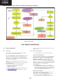
Service Modes, Error Codes, and Fault Finding (continued)
5.5
Error Codes
5.5.1
Introduction
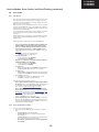
The error code buffer contains all detected errors since the last
time the buffer was erased. The buffer is written from left to
right, new errors are logged at the left side, and all other errors
shift one position to the right.
When an error occurs, it is added to the list of errors, provided
the list is not full. When an error occurs and the error buffer is
full, then the new error is not added, and the error buffer stays
intact (history is maintained).
To prevent that an occasional error stays in the list forever, the
error is removed from the list after more than 50 hrs. of
operation.
When multiple errors occur (errors occurred within a short time
span), there is a high probability that there is some relation
between them.
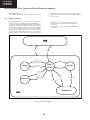
New in this chassis is the way errors can be displayed:
•
•
•
•
•
•
•
If no errors are there, the LED should not blink at all in
CSM or SDM. No spacer must be displayed as well.
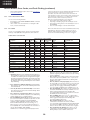
There is a simple blinking LED procedure for board
level repair (home repair) so called LAYER 1 errors
next to the existing errors which are LAYER 2 errors (see
Table 5-2).
– LAYER 1 errors are one digit errors.
– LAYER 2 errors are 2 digit errors.
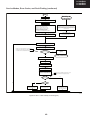
In protection mode.
– From consumer mode: LAYER 1.
– From SDM mode: LAYER 2.
Fatal errors, if I2C bus is blocked and the set reboots,
CSM and SAM are not selectable.
– From consumer mode: LAYER 1.
– From SDM mode: LAYER 2.
In CSM mode.
– When entering CSM: error LAYER 1 will be displayed
by blinking LED. Only the latest error is shown.
In SDM mode.
– When SDM is entered via Remote Control code or the
hardware pins, LAYER 2 is displayed via blinking LED.
Error display on screen.
– In CSM no error codes are displayed on screen.
– In SAM the complete error list is shown.
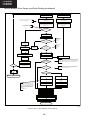
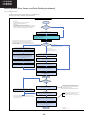
Basically there are three kinds of errors:
• Errors detected by the Stand-by software which lead to
protection. These errors will always lead to protection and
an automatic start of the blinking LED LAYER 1 error.
(see section “5.6 The Blinking LED Procedure”).
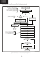
• Errors detected by the Stand-by software which not
lead to protection. In this case the front LED should blink
the involved error. See also section “5.5 Error Codes, 5.5.4
Error Buffer”. Note that it can take up several minutes
before the TV starts blinking the error (e.g. LAYER 1
error = 2, LAYER 2 error = 15 or 53).
•
5.5.2
Errors detected by main software (MIPS). In this case
the error will be logged into the error buffer and can be
read out via blinking LED method LAYER 1-2 error, or in
case picture is visible, via SAM.
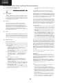
How to Read the Error Buffer
Use one of the following methods:
• On screen via the SAM (only when a picture is visible).
E.g.:
– 00 00 00 00 00: No errors detected
– 23 00 00 00 00: Error code 23 is the last and only
detected error.
– 37 23 00 00 00: Error code 23 was first detected and
error code 37 is the last detected error.
– Note that no protection errors can be logged in the
error buffer.
55