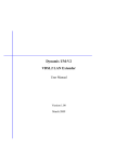
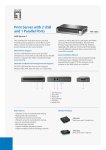
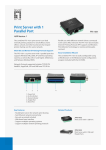
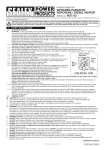
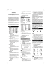
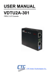
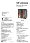
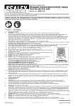
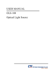
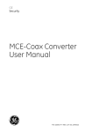
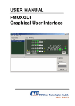
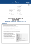
1
VDTU2-B110 VDSL2 LAN Extender 1 Copyright by CTC UNION Communications Inc., all right reserved The information in this document has been checked carefully and is believed to be correct as of the date of publication. CTC UNION Communications Inc. reserves the right to make changes in the product of specification, or both, presented in this publication at any time without notice. CTC UNION Communications assumes no responsibility or liability arising from the specification listed herein. CTC UNION Communications make no representations that the use of its products in the manner described in this publication will not infringe on existing or future patents, trademark, copyright, or rights of third parties. Implication or other under any patent or patent rights of CTC UNION Communications Ins. grants no license. All other trademarks and registered trademarks are the property of their respective holders. CTC Union Technologies Co., Ltd. Far Eastern Vienna Technology Center (Neihu Technology Park) 8F, No. 60, Zhouzi St. Neihu, Taipei, 114 Taiwan Phone: +886-2-2659-1021 FAX: +886-2-2799-1355 User Manual Version 2.00 March 2013 This document is the current official release manual. Please check CTC Union's website for any updated manual or contact us by E-mail at [email protected]. Please address any comments for improving this manual or to point out omissions or errors to [email protected]. Thank you. 2 Table of Contents Chapter 1 Introduction .............................................................................................................................. 4 1.1 Features ........................................................................................................................................................ 4 1.2 Specification .................................................................................................................................................. 5 1.3 Applications................................................................................................................................................... 6 Chapter 2 Hardware Installation................................................................................................................ 7 2.1 Front Panel .................................................................................................................................................... 7 2.2 Rear Panel ................................................................................................................................................... 10 2.3 Installation .................................................................................................................................................. 11 Appendix I ................................................................................................................................................12 Appendix II ...............................................................................................................................................14 3 Chapter 1 Introduction 100M VDSL2 Ethernet Extender is a high-speed Ethernet Extender with one Ethernet port (RJ-45 connector) and one VDSL port (RJ-45 connector). It is a bridge mode modem, well accommodating VDSL2 (Very-high-data-rate Digital Subscriber Loop) technology to extend Ethernet service over single-pair phone line. It is compliant to ITU-T G.993.2 standard and supports VDSL2 30a profile that features 100Mbps of symmetric data rate over the existing copper wires. Supporting both symmetric and asymmetric transmission, it can reach up to 100/100 Mbps bandwidth (line rate) within 300M or 10/10 Mbps (line rate) for 1 Km long range connections. By providing ultra-high speed, the VDSL2 100M Ethernet Extender makes your telephone line achieve its best performance than before. It has the advantage of minimum installation time (simply as plug-n-play) and minimum expense by allowing video streaming and data to share the same telephone pair without interference. 100M VDSL2 Ethernet Extender delivers everything needed to quickly deploy a high-speed IP-based network for providing high-speed Internet access, video-on demand services and voice services. The resulting compact, cost-effective form factor offers Systems Integrators, small business owners an attractive Long Reach Ethernet solution. 1.1 Features Cost effective bridge function to connect two Ethernet LAN Support flow control on Fast Ethernet port via PAUSE frame or Back Pressure IEEE 802.1Q VLAN tag transparent Easy installation via simple plug-and-play Selectable CPE and CO mode via DIP switch: Two working modes are built in the same unit, which keep the flexibility of installation and easy provision of service but lower inventory of service provider Selectable VDSL2 profile mode (17a or 30a): Support up to VDSL2 30a profile to ensure high data rate. Selectable target band plan: Symmetric: Support the band plan G.997 and provide the symmetric transmission on both downstream and upstream. Asymmetric: Provides highest line rate in short range in asymmetric mode. Selectable target SNR margin Compatible with the 724M/708M DSLAM & third party DSLAM. Compatible with the 2U 19-inch, 17-slot chassis. 4 1.2 Specification 4-position DIP Switch LAN Interface: Selectable CO or CPE mode RJ-45 connector Selectable 30a or 17a (VDSL2 Profile) Complying with IEEE Selectable Band plan (Symmetric or Asymmetric) Selectable target SNR margin (6dB or 9dB) 802.3/802.3u/802.3x LED: 10/100 Base-T Auto-Negotiation, Auto-MDI/MDI-X. LAN: ACT/LNK,10/100Mpbs, Half/Full Duplex VDSL: Power On/Off, CO/CPE, Idle/Trained/Link Performance* (AWG24 Wire) Downstream/ Upstream 17a Profile 600M 1000M 42/46 Mbps 18/13 Mbps 1500M 12/3 Mbps 40/45 Mbps 22/19 Mbps 1200M 16/7 Mbps 1800M 2100M 8/2 Mbps 5/2 Mbps RJ-45 connector DMT Encoding Complying with ITU-T G993.1/993.2/G.997.1 2000M 5/2 Mbps 30a Profile 600M 900M VDSL Interface: On-board surge protection Regulatory Compliance CE FCC Part 15 Class B EN60950 Power supply: DC single 12 Volt over 2.0 mm DC jack; 4.2 Watt maximum. Dimension: 73.4mm x 96.2mm x 22.8mm Temperature: 0°C ~45°C Humidity: 0%~95%RH (non-condensing) *The above performance data is for reference only, the actual data rate may vary depending on the quality of the copper wire and environmental factors. 5 1.3 Applications LAN Extender Application 6 Chapter 2 Hardware Installation This chapter shows the front panel and how to install the hardware. 2.1 Front Panel Front panel can be separated into five parts from left to right: (1) DIP switch (2) RJ-45 connector for Ethernet (3) LEDs for Ethernet (4) LEDs for VDSL (5) RJ-45 connector for VDSL 7 1. The RJ-45 is designed to connect to the Local Network with the Unshielded Twisted Pair (UTP) cable. The LEDs on top of RJ-45 connector show the status below: 2. LEDs for LAN blinking Activity LED PWR(Power LED) LNK(Ethernet LED) LNK RT(VDSL Link) FUL 100(LAN Link) Color Green Green Green Green Green Green Green Green Green Green Green Status On Off On Blinking Off On Blinking Off On Blinking Off On Off Link UP Link UP 100Mbps 10Mbps Full Duplex Half Duplex Descriptions Lights to indicate that the VDSL2 bridge had power The device is not ready or has malfunctioned. The device has good Ethernet connection. The device is sending or receiving data. The LAN not connected. RT mode. Handshaking/Transmit & Received data The device not ready. The device is link on 100M Full duplex and ready. The device is sending or receiving data. The device is link on 10M Full duplex and ready. 8 3. The following table describes the DIP Switches’ setting. Pin 1 Pin 2 Pin 3 Pin 4 Side Channel Rate Limit SNR Off OT 30a Symmetric 9dB On RT 17a Asymmetric 6dB Pin 1: OT, RT switch OT: LAN Extender acts as Central Office (CO) side. RT: LAN Extender acts as Customer Premise Equipment (CPE) side. Pin 2: Impulse noise protection 30a: High Speed Mode. Provides communication protection for up to 250ms impulse noise with latency less than 6 ms. 17a: Long Reach Mode. Direct data transmission with latency less than 1 ms. Pin 3: Band Plan Symmetric: Support the band plan G.997 and provide the symmetric transmission on both downstream and upstream. Asymmetric: Provides highest line rate in short range in asymmetric mode. Pin 4: General protection 9dB: Better channel noise protection with SNR up to 9 dB 6dB: Original channel noise protection with 6 dB SNR. 9 4. The following table describes the LEDs’ function of the product. LEDs for VDSL blinking Slow: Fast: Idle Training On Off Device Power ON Device Power OFF CPE-mode CO-mode Linked Off line 2.2 Rear Panel The DC Jack on the rear panel can be connected to power supply adaptor with the DC input. 10 2.3 Installation Please see the illustration below 11 Appendix I Connector Architecture Ethernet Port Connector (RJ-45) The Ethernet Port interface is an 8 position Modular Jack. The table below displays the pin out assignments. Pin Number Assignment (MDI-X) 1 RX+; Receive data + 2 RX-; Receive data - 3 TX+; Transmit data + 4 Not used 5 Not used 6 TX-; Transmit Data - 7 Not used 8 Not used Figure 1 8 1 8 Front View Top 12 View VDSL Interface Pin Assignments (RJ-45) The VDSL interface is standard eight-pin modular jack. The table below displays the pin out assignments. Pin Number Description 1 Not used 2 Not used 3 Not used 4 ANALOG Input/Output 5 ANALOG Input/Output 6 Not used 7 Not used 8 Not used Figure 1 8 1 8 Front View Top 13 View VDSL LAN Extender User Manual V200 Appendix II Chassis Accessory There is also the Chassis solution for application on the rack in CO side. The major feature of the Chassis is listed below: • 2U, 19”, 17-Slot rack • • Support 17-slot in one unit Power Input: AC: 100 ~240V or DC48: 36 ~ 60V • • Cross flow cooling fan built-in 100M units are hot swappable Specifications Power Input: AC : 100 ~240V or DC48 : 36 ~ 60V Power Consumption: >60W Dimensions: 76 X 212 X 88 mm (D x W x H ) Weight: 7.9Kg Temperature: 0 ~ 50°C (Operating), -10 ~ 70°C (Storage) Humidity: 10 ~ 90% non-condensing Certification; CE, FCC, RoHS Compliant MTBF: 65,000 hrs 14