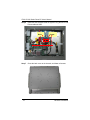
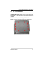
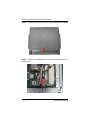
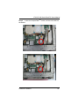
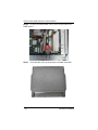
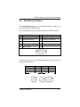
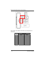
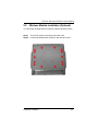
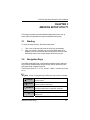
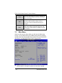
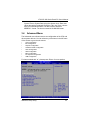
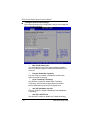
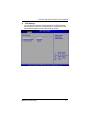
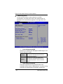
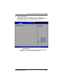
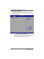
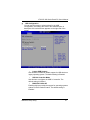
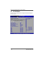
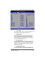
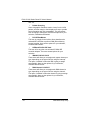
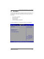
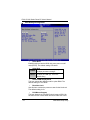
1
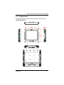
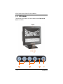
IFO2175-830 Series All-In-One 17” Super Slim & Fanless Panel Computer User’s Manual Disclaimers This manual has been carefully checked and believed to contain accurate information. AXIOMTEK Co., Ltd. assumes no responsibility for any infringements of patents or any third party’s rights, and any liability arising from such use. AXIOMTEK does not warrant or assume any legal liability or responsibility for the accuracy, completeness or usefulness of any information in this document. AXIOMTEK does not make any commitment to update the information in this manual. AXIOMTEK reserves the right to change or revise this document and/or product at any time without notice. No part of this document may be reproduced, stored in a retrieval system, or transmitted, in any form or by any means, electronic, mechanical, photocopying, recording, or otherwise, without the prior written permission of AXIOMTEK Co., Ltd. ©Copyright 2010 AXIOMTEK Co., Ltd. All Rights Reserved May 2010, Version A2 Printed in Taiwan ii Safety Approvals CE Marking FCC Class A FCC Compliance This equipment has been tested in compliance with the limits for a Class A digital device, pursuant to Part 15 of the FCC Rules. These limits are meant to provide reasonable protection against harmful interference in a residential installation. If not installed and used in accordance with proper instructions, this equipment might generate or radiate radio frequency energy and cause harmful interference to radio communications. However, there is no guarantee that interference will not occur in a particular installation. If this equipment does cause harmful interference to radio or television reception, which can be determined by turning the equipment off and on, the user is encouraged to try to correct the interference by one or more of the following methods: 1. Reorient or relocate the receiving antenna. 2. Increase the separation between the equipment and receiver. 3. Connect the equipment to another outlet of a circuit that doesn’t connect with the receiver. 4. Consult the dealer or an experienced radio/TV technician for help. Shielded interface cables must be used in order to comply with the emission limits. iii Safety Precautions Before getting started, read the following important safety precautions. 1. 2. 3. 4. 5. 6. 7. 8. 9. 10. iv The IFO2175-830 Series does not come equipped with an operating system. An operating system must be loaded first before installing any software into the computer. Be sure to ground yourself to prevent static charge when installing the internal components. Use a grounding wrist strap and place all electronic components in any staticshielded devices. Most electronic components are sensitive to static electrical charge. Disconnect the power cord from the IFO2175-830 Series before any installation. Be sure both the system and external devices are turned OFF. A sudden surge of power could ruin sensitive components that the IFO2175-830 Series must be properly grounded. Make sure it is the correct voltage of the power source before connecting the equipment to the power outlet. The brightness of the flat panel display will be getting weaker as a result of frequent usage. However, the operating period varies depending on the application environment. Turn OFF the system power before cleaning. Clean the system using a cloth only. Do not spray any liquid cleaner directly onto the screen. The IFO2175-830 Series may come with or w/o a touchscreen. Although the touchscreen is chemical resistant, it is recommended that you spray the liquid cleaner on a cloth first before wiping the screen. In case your system comes without the touchscreen, you must follow the same procedure and not spray any cleaner on the flat panel directly. Avoid using sharp objects to operate the touchscreen. Scratches on the touchscreen may cause malfunction or internal failure to the touchscreen. The flat panel display is not susceptible to shock or vibration. When assembling the IFO2175-830 Series, make sure it is securely installed. Do not leave this equipment in an uncontrolled environment where the storage temperature is below -20℃ or above 60℃. It may damage the equipment. External equipment intended for connection to signal 11. input/out or other connectors shall comply with relevant UL/IEC standard. Do not open the system’s back cover. If opening the cover for maintenance is a must, only a trained technician is allowed to do so. Integrated circuits on computer boards are sensitive to static electricity. To avoid damaging chips from electrostatic discharge, observe the following precautions: z Before handling a board or integrated circuit, touch an unpainted portion of the system unit chassis for a few seconds. This will help to discharge any static electricity on your body. z When handling boards and components, wear a wristgrounding strap, available from most electronic component stores. Classification 1. 2. 3. 4. 5. Degree of production against electric shock: not classified Degree of protection against the ingress of water: IPX1 Equipment not suitable for use in the presence of a flammable anesthetic mixture with air or with oxygen or nitrous oxide. Mode of operation: Continuous Type of protection against electric shock: Class I equipment v General Cleaning Tips You may need the following precautions before you begin to clean the computer. When you clean any single part or component for the computer, please read and understand the details below fully. 1. 2. 3. 4. 5. 6. When you need to clean the device, please rub it with a piece of dry cloth. Be cautious of the tiny removable components when you use a vacuum cleaner to absorb the dirt on the floor. Turn the system off before you start to clean up the component or computer. Never drop the components inside the computer or get circuit board damp or wet. Be cautious of all kinds of cleaning solvents or chemicals when you use it for the sake of cleaning. Some individuals may be allergic to the ingredients. Try not to put any food, drink or cigarette around the computer. Cleaning Tools: Although many companies have created products to help improve the process of cleaning your computer and peripherals users can also use household items to clean their computers and peripherals. Below is a listing of items you may need or want to use while cleaning your computer or computer peripherals. Keep in mind that some components in your computer may only be able to be cleaned using a product designed for cleaning that component, if this is the case it will be mentioned in the cleaning. z Cloth: A piece of cloth is the best tool to use when rubbing up a component. Although paper towels or tissues can be used on most hardware as well, we still recommend you to rub it with a piece of cloth. z Water or rubbing alcohol: You may moisten a piece of cloth a bit with some water or rubbing alcohol and rub it on the computer. Unknown solvents may be harmful to the plastics parts. z Vacuum cleaner: Absorb the dust, dirt, hair, cigarette particles, and other particles out of a computer can be one of the best methods of cleaning a computer. Over time these items can restrict the airflow in a computer and cause circuitry to corrode. vi z z Cotton swabs: Cotton swaps moistened with rubbing alcohol or water are excellent tools for wiping hard to reach areas in your keyboard, mouse, and other locations. Foam swabs: Whenever possible it is better to use lint free swabs such as foam swabs. Note We strongly recommended that you should shut down the system before you start to clean any single components. Please follow the steps below: 1. Close all application programs 2. Close operating software 3. Turn off power switch 4. Remove all device 5. Pull out power cable vii Scrap Computer Recycling If the computer equipments need the maintenance or are beyond repair, we strongly recommended that you should inform your Axiomtek distributor as soon as possible for the suitable solution. For the computers that are no longer useful or no longer work well, please contact your Axiomtek distributor for recycling and we will make the proper arrangement. Trademarks Acknowledgments AXIOMTEK is a trademark of AXIOMTEK Co., Ltd. IBM, PC/AT, PS/2, VGA are trademarks of International Business Machines Corporation. ® ® Intel and Pentium are registered trademarks of Intel Corporation. MS-DOS, Microsoft C and QuickBASIC are trademarks of Microsoft Corporation. VIA is a trademark of VIA Technologies, Inc. SST is a trademark of Silicon Storage Technology, Inc. UMC is a trademark of United Microelectronics Corporation. Other brand names and trademarks are the properties and registered brands of their respective owners. viii Table of Contents Disclaimers ....................................................................................ii Safety Approvals .......................................................................... iii Safety Precautions .......................................................................iv Classification .................................................................................v General Cleaning Tips..................................................................vi Scrap Computer Recycling......................................................... viii CHAPTER 1 INTRODUCTION.......................................................... 1 1.1 General Description .................................................... 1 1.2 Features...................................................................... 2 1.3 System Specifications................................................. 2 1.4 Dimensions ................................................................. 5 1.5 I/O Outlets................................................................... 6 1.6 Packing List................................................................. 8 1.7 Power Switch ............................. 錯誤! 尚未定義書籤。 CHAPTER 2 HARDWARE INSTALLATION .................................. 10 2.1 DRAM Installation ..................................................... 10 2.2 Hard Disk Drive Installation ...................................... 13 2.3 CF Card Installation .................................................. 17 2.4 Serial Ports Interface ................................................ 21 2.5 Wireless Module Installation (Optional) .................... 23 2.6 Mountings (Optional) ................................................ 27 2.6.1 Wallmount (Optional) ................................................ 27 2.6.2 VESA Mount (Optional) ............................................ 28 2.6.3 Desktop Stand (Optional) ......................................... 29 CHAPTER 3 AMI BIOS SETUP UTILITY ....................................... 33 3.1 Starting...................................................................... 33 3.2 Navigation Keys ........................................................ 33 3.3 Main Menu ................................................................ 34 3.4 Advanced Menu ........................................................ 35 3.5 PCI PnP Menu .......................................................... 48 3.6 Boot Menu................................................................. 51 3.7 Security Menu ........................................................... 56 3.8 Chipset Menu............................................................ 58 3.9 Exit Menu .................................................................. 63 ix CHAPTER 4 DRIVER INSTALLATION .......................................... 65 4.1 System ...................................................................... 65 4.2 Touch Screen............................................................ 66 4.2.1 Specification.............................................................. 66 4.2.2 Driver Installation ...................................................... 67 x MEMO xi IFO2175-830 Series Panel PC User’s Manual CHAPTER 1 INTRODUCTION This chapter contains general information and detailed specifications of the IFO2175-830 Series. Chapter 1 includes the following sections: 1.1 General Description Features System Specification Dimensions I/O Outlets Package List General Description The IFO2175-830 is an ultra slim panel computer equipped with 17inch 300nits high brightness SXGA LCD display and supports superior Intel○R AtomTM N270 1.6GHz processor with FSB 533MHz. ® Powered by Intel 945GSE +ICH7M core logic chipset, this panel computer has better graphic performance. The panel also supports Dual View and multiple I/O options including 4 USB 2.0, 4 RS-232 ports. Furthermore, the IFO2175-830 supports antenna for wireless (802.11 b/g) expansion. The IFO2175-830 is designed to work with low noise, low power consumption, high reliability and high performance applications. Besides, excellent ID (industrial design) and user friendly interface design make the IFO2175-830 perfect with super slim, professional outlook, better user interface, and excellent protection at once! This safe, reliable & user-friendly panel computer can ensure customer’s project success and best suited for PIO/POS/kiosk, media content display, and HMI solutions. Introduction 1 IFO2175-830 Series Panel PC User’s Manual 1.2 1.3 Features ¾ 17” high brightness ( 380nits) SXGA TFT LCD ¾ Intel○R AtomTM N270 1.6GHz processor with FSB 533MHz onboard ¾ NEMA 4/12 (IP65) - compliant front bezel ¾ IPx1 – whole enclosure ¾ Fanless and noiseless operation ¾ Optional 1.3 mega pixels camera ¾ Optional wireless (802.11 b/g) antenna System Specifications FRONT BEZEL PLASTIC ABS LCD PANEL DISPLAY TYPE BRIGHTNESS (cd/m²) RESOLUTION VIEWING ANGLE (H/V) 2 17" SXGA TFT 380 nits 1280 x 1024 160º/160º Introduction IFO2175-830 Series Panel PC User’s Manual MAIN SYSTEM CPU Intel○R AtomTM N270 1.6GHz processor with FSB 533MHz CHIPSET INTEL 945GSE+ICH7M SYSTEM MEMORY STORAGE OPTICAL DRIVE ® SUPPORTS 1 DDR2 SODIMM MEMORY UP TO 2 GB 1 x 2.5" SATA HDD DRIVE BAY OPTIONAL 1 COMPACT COMBO DRIVE 1 x RS-232/RS-422/RS-485 (COM 1) 3 x RS-232 4 x USB 2.0 I/O CONNECTORS 1 x PS/2 MOUSE AND KEYBOARD 1 x AUDIO (MIC-IN/LINE-OUT) 1 x VGA 2 x 10/100/1000Mbps ETHERNET 1 x 12V DC-IN POWER CONNECTOR CAMERA 1 x 1.3 MEGA PIXELS CAMERA (option) RESISTIVE TYPE TOUCHSCREEN LIGHT TRANSMISSION: 80% TOUCH LIFETIME: 35 MILLION TOUCHES POWER SUPPLY 12VDC, w/ AC-DC POWER ADAPTOR 437.98mm (17.24") (W) x 76.5mm (3.01") (D) x DIMENSIONS 376.41mm (14.81") (H) 7.65kg (16.85 lb) WEIGHT Introduction 3 IFO2175-830 Series Panel PC User’s Manual OPERATION TEMPERATURE: 0ºC~40ºC (32ºF~104ºF) ENVIRONMENTA RELATIVE HUMIDITY: 10%~95%, NONL CONDESING SHOCK: 10G PEAK ACCELERATION (11 SEC. DURATION) CERTIFICATION CE NOTE All specifications and images are subject to change without notice. NOTE If it is operated in high temperature environment, the wide temperature DRAM and HDD are recommended. 4 Introduction IFO2175-830 Series Panel PC User’s Manual 1.4 Dimensions The following diagrams show you dimensions and outlines of the IFO2175-830 Series. Introduction 5 IFO2175-830 Series Panel PC User’s Manual 1.5 I/O Outlets The following figures show you the locations of the IFO2175-830 Series I/O outlets. ○ 1 6 ○ 2 ○ 3 ○ 4 Introduction IFO2175-830 Series Panel PC User’s Manual ¾ I/O Outlets Introduction NO CONNECTOR 1 2 3 4 5 6 7 8 9 10 11 12 13 14 BRIGHTNESS ADJUST BUTTONS VOLUME ADJUST BUTTONS POWER LED POWER SWITCH DC-IN POWER CONNECTOR COM 1 (RS-232/422/485) COM 2 (RS-232) VGA ETHERNET USB 2.0 x 2 AUDIO (LINE-OUT) USB 2.0 x 2 COM 3 (RS-232) COM 4 (RS-232) 7 IFO2175-830 Series Panel PC User’s Manual 1.6 Packing List The package bundled with your IFO2175-830 should contain the following items: IFO2175-830 Series Unit x 1 12VDC, w/ AC-DC Power Adaptor Power Cord x 1 CD x 1 (For Driver and User’s Manual) DVD-combo Cover x 2 (For within DVD-combo) (option) SATA cable x 1 Cable Management Kit x 2 Fuse x 1 Wall-Mount Bracket x 1 M4 x 8 Screws x 4 (for VESA Mounting) M3 x 5 Screws x 2 (for Cable Management Kit) z z z z z z z z z z z If you can not find this package or any items are missing, please contact AXIOMTEK distributors immediately. 8 Introduction IFO2175-830 Series Panel PC User’s Manual MEMO Introduction 9 IFO2175-830 Series Panel PC User’s Manual CHAPTER 2 HARDWARE INSTALLATION The IFO2175-830 Series are convenient for your various hardware configurations, such as CPU (Central Processing Unit) and HDD (Hard Disk Drive). The chapter 2 will show you how to install the hardware. It includes: 2.1 DRAM Installation The IFO2175-830 provides one 200-pin DDR2 SODIMM sockets that support system memory up to 2GB. Please follow steps below to install the memory modules: Step 1 Turn off the system, and unplug the Power cord. Step 2 Locate and release these screws to open the back cover 10 Hardware Installation IFO2175-830 Series Panel PC User’s Manual Step 3 Please open the back cover by lifting the joint part as marked. Step 4 Open the back cover and find mainboard Hardware Installation 11 IFO2175-830 Series Panel PC User’s Manual Step 5 Push down latches on each side of the DIMM socket. Step 6 Install the memory module into the socket and push it firmly down until it is fully seated. The socket latches are levered upwards and clipped on to the edges of the DIMM. 12 Hardware Installation IFO2175-830 Series Panel PC User’s Manual 2.2 Hard Disk Drive Installation The IFO2175-830 Series offers a convenient drive bay module for users to install HDD. The system offers users one 2.5” Hard Disk Drive for installation. Please follow the steps: Step 1 Turn off the system, and unplug the Power cord. Step 2 Locate and release these screws to open the back cover. Hardware Installation 13 IFO2175-830 Series Panel PC User’s Manual Step 3 Please open the back cover by lifting the joint part as marked. Step 4 Locate the HDD socket as marked. 14 Hardware Installation IFO2175-830 Series Panel PC User’s Manual Step 5 Use assembly parts to fix HDD with the bracket. 1. HDD Bracket x1 2. 2.5 inch Hard-disk 3. Screw x 4 4. Assembly the HDD with the bracket. ATTENTION Please follow the direction of Hard-disk installation. “Hard-disk PCB facesup”. Hardware Installation 15 IFO2175-830 Series Panel PC User’s Manual Step 6 Install the HDD bracket inside the system. Plug the SATA and Power cables in HDD. Data Step 7 16 Power Close the back cover to the chassis, and fasten all screws. Hardware Installation IFO2175-830 Series Panel PC User’s Manual 2.3 CF Card Installation The IFO2175-830 series provides one CF slot for users to install CompactFlash™ card. Please refer to the following instructions for installation: Step 1 Turn off the system, and unplug the Power cord. Step 2 Locate and release these screws to open the back cover. Hardware Installation 17 IFO2175-830 Series Panel PC User’s Manual Step 3 Please open the back cover by lifting the joint part as marked. Step 4 Unplug the CD-ROM Power cord, if IFO2175-830 is with CDROM version. 18 Hardware Installation IFO2175-830 Series Panel PC User’s Manual Step 5 Locate the CompactFlash the socket. Hardware Installation TM socket, and insert the card into 19 IFO2175-830 Series Panel PC User’s Manual Step 6 Plug the CD-ROM Power cord, if IFO2175-830 is with CDROM version. Step 7 20 Close the back cover to the chassis, and fasten all screws. Hardware Installation IFO2175-830 Series Panel PC User’s Manual 2.4 Serial Ports Interface The IFO2175-830 series has two onboard serial ports, COM1 (RS232/ 422/ 485) and COM2 (RS-232). The following table shows you the pin assignments of this connector: Pin Signal Pin Signal 1 Data Carrier Detect (DCD) 6 Data Set Ready (DSR) 2 Receive Data (RXD) 7 Request To Send (RTS) 3 Transmit Data (TXD) 8 Clear To Send (CTS) 4 Data Terminal Ready (DTR) 9 Ring Indicator (RI) 5 Ground (GND) In addition, COM1 can be set for RS-232/422/485 by jumper. The jump setting is listed as below: COM1 JP11 JP12 JP13 RS-232 (default) RS-422 RS-485 3-5, 4-6 1-3, 2-4 1-3, 2-4 3-5, 4-6 1-3, 2-4 1-3, 2-4 1-2 3-4, 7-8 5-6, 7-8 Hardware Installation 21 IFO2175-830 Series Panel PC User’s Manual When COM1 is set to RS-422 or RS-485, the pin assignments are listed below: Pin # 1 2 3 4 5 6 7 8 9 22 Signal Name RS-422 RS-485 TXTX+ RX+ RXNo connector No connector No connector No connector GND DATADATA+ No connector No connector No connector No connector No connector No connector GND Hardware Installation IFO2175-830 Series Panel PC User’s Manual 2.5 Wireless Module Installation (Optional) You can follow the steps below to install an optional wireless module. Step 1 Turn off the system, and unplug the Power cord. Step 2 Locate and release these screws to open the back cover. Hardware Installation 23 IFO2175-830 Series Panel PC User’s Manual Step 3 Please open the back cover by lifting the joint part as marked. Step 4 Open the back cover and find mainboard (SBC87830). 24 Hardware Installation IFO2175-830 Series Panel PC User’s Manual Step 5 The socket latches are clipped on to the edges of the Mini card. Install wireless LAN card to the socket. ○ 1 ○ 2 Step 6 There are two choices of antennas which are installed in IFO2175-830 series. One is build-in antennas. The other is external antennas. Please follow the steps: Hardware Installation 25 IFO2175-830 Series Panel PC User’s Manual Step 7 Find the built-in Antenna cable which is tied with other cables on the bottom of the device. There are two connectors on wireless LAN card. One is MAIN, and the other is AUX. Connect antenna cable to MAIN connector on wireless LAN card. Step 8 26 Close the back cover to the chassis, and fasten all screws. Hardware Installation IFO2175-830 Series Panel PC User’s Manual 2.6 Mountings (Optional) There are several mounting ways for the IFO2175-830 Series, Wallmount, VESA and Desktop mountings as below: 2.6.1 Wallmount (Optional) The mounting for IFO2175-830 Series is Wallmount as below: Step 1 Prepare all parts for installing the wallmount kit. Step 2 Assemble the mallmount kit by using screws to fix the backplane. 1 ○ Hardware Installation 2 ○ 27 IFO2175-830 Series Panel PC User’s Manual 2.6.2 VESA Mount (Optional) The mounting for IFO2175-830 Series is VESA-Arm as below: Assemble the VESA-Arm by using screws to fix the backplane. 28 Hardware Installation IFO2175-830 Series Panel PC User’s Manual 2.6.3 Desktop Stand (Optional) The IFO2175-830 Series provides you with an optional Desktop Stand that you can follow the steps below: Step 1 Prepare the parts of desktop stand. Screw A Screw B Screw C Hinge Cover Hardware Installation 29 IFO2175-830 Series Panel PC User’s Manual Step 2 Assemble the desktop stand. Fix the screws as marked on the bottom side of chassis. (Use Screw A) Step 3 Fix the screws as marked on the back side of chassis (Use Screw B). 30 Hardware Installation IFO2175-830 Series Panel PC User’s Manual Step 3 Fix the desktop stand firmly. Rear View Front View Hardware Installation 31 IFO2175-830 Series Panel PC User’s Manual MEMO 32 Hardware Installation IFO2175-830 Series Panel PC User’s Manual CHAPTER 3 AMI BIOS SETUP UTILITY This chapter provides users with detailed description how to set up basic system configuration through the AMI BIOS setup utility. 3.1 Starting To enter the setup screens, follow the steps below: 1. 2. Turn on the computer and press the <Del> key immediately. After you press the <Delete> key, the main BIOS setup menu displays. You can access the other setup screens from the main BIOS setup menu, such as the Chipset and Power menus. 3.2 Navigation Keys The BIOS setup/utility uses a key-based navigation system called hot keys. Most of the BIOS setup utility hot keys can be used at any time during the setup navigation process. These keys include <F1>, <F10>, <Enter>, <ESC>, <Arrow> keys, and so on. Note Some of navigation keys differ from one screen to another. Å Left/Right The Left and Right <Arrow> keys allow you to select a setup screen. ÇÈ Up/Down The Up and Down <Arrow> keys allow you to select a setup screen or sub-screen. +− Plus/Minus The Plus and Minus <Arrow> keys allow you to change the field value of a particular setup item. Tab F1 The <Tab> key allows you to select setup fields. The <F1> key allows you to display the General Help screen. AMI BIOS Setup Utility 33 IFO2175-830 Series Panel PC User’s Manual F10 The <F10> key allows you to save any changes you have made and exit Setup. Press the <F10> key to save your changes. Esc The <Esc> key allows you to discard any changes you have made and exit the Setup. Press the <Esc> key to exit the setup without saving your changes. Enter 3.3 The <Enter> key allows you to display or change the setup option listed for a particular setup item. The <Enter> key can also allow you to display the setup sub- screens. Main Menu When you first enter the Setup Utility, you will enter the Main setup screen. You can always return to the Main setup screen by selecting the Main tab. There are two Main Setup options. They are described in this section. The Main BIOS Setup screen is shown below. z System Time/Date Use this option to change the system time and date. Highlight 34 AMI BIOS Setup Utility IFO2175-830 Series Panel PC User’s Manual System Time or System Date using the <Arrow> keys. Enter new values through the keyboard. Press the <Tab> key or the <Arrow> keys to move between fields. The date must be entered in MM/DD/YY format. The time is entered in HH:MM:SS format. 3.4 Advanced Menu The Advanced menu allows users to set configuration of the CPU and other system devices. You can select any of the items in the left frame of the screen to go to the sub menus: y y y y y y y y y CPU Configuration IDE Configuration SuperIO Configuration Hardware Health Configuration ACPI Configuration APM Configuration MPS Configuration PCI Express Configuration USB Configuration For items marked with “f”, please press <Enter> for more options. AMI BIOS Setup Utility 35 IFO2175-830 Series Panel PC User’s Manual z Configure advanced CPU settings This screen shows the CPU Configuration, and you can change the value of the selected option. ¾ Max CPUID Value Limit You can enable this item to let legacy operating systems boot even without support for CPUs with extended CPU ID functions. ¾ Execute-Disable Bit Capability This item helps you enable or disable the No-Execution Page Protection Technology. ¾ Hyper Threading Technology Use this item to enable or disable Hyper-Threading Technology, which makes a single physical processor perform multi-tasking function as two logical ones. ¾ Intel (R) SpeedStep (tm) tech This item helps you enable or disable the Intel SpeedStep Technology. ¾ Intel (R) C-STATE tech Use this item to enable or disable the C-State technology. 36 AMI BIOS Setup Utility IFO2175-830 Series Panel PC User’s Manual ¾ Enhanced C-States This item allows you to enable or disable any available enhanced C-states (C1E, C2E, C3E, C4E and Hard C4E). z IDE Configuration You can use this screen to select options for the IDE Configuration, and change the value of the selected option. A description of the selected item appears on the right side of the screen. For items marked with “f”, please press <Enter> for more options. ¾ Primary/Secondary/Third IDE Master/Slave Select one of the hard disk drives to configure IDE devices installed in the system by pressing <Enter> for more options. SuperIO Configuration You can use this screen to select options for the SuperIO Configuration, and change the value of the selected option. A description of the selected item appears on the right side of the screen. z AMI BIOS Setup Utility 37 IFO2175-830 Series Panel PC User’s Manual ¾ Serial Port1 Address This item specifies the base I/O port address and Interrupt Request address of serial port 1. The Optimal setting is 3F8/IRQ4. The Fail-Safe default setting is 3F8. ¾ Serial Port1 IRQ This item specifies the IRQ used by the serial port 1. Serial Port2 Address This item specifies the base I/O port address and Interrupt Request address of serial port 2. The Optimal setting is 2F8/IRQ3. The Fail-Safe setting is 2F8. ¾ ¾ Serial Port2 IRQ This item specifies the IRQ used by the serial port 2. ¾ Serial Port3 Address This item specifies the base I/O port address and Interrupt Request address of serial port 3. ¾ Serial Port3 IRQ This item specifies the IRQ used by the serial port 3. 38 AMI BIOS Setup Utility IFO2175-830 Series Panel PC User’s Manual ¾ Serial Port4 Address This item specifies the base I/O port address and Interrupt Request address of serial port 4. ¾ Serial Port4 IRQ This item specifies the IRQ used by the serial port 4. AMI BIOS Setup Utility 39 IFO2175-830 Series Panel PC User’s Manual z Hardware Health Configuration This screen shows the Hardware Health Configuration, and a description of the selected item appears on the right side of the screen. ¾ System Temperature/CPU Temperature These items display the temperature of CPU and System, Vcore, etc. 40 AMI BIOS Setup Utility IFO2175-830 Series Panel PC User’s Manual z ACPI Settings You can use this screen to select options for the ACPI Settings, and change the value of the selected option. A description of the selected item appears on the right side of the screen. AMI BIOS Setup Utility 41 IFO2175-830 Series Panel PC User’s Manual z APM Configuration You can use this screen to select options for the APM Configuration, and change the value of the selected option. A description of the selected item appears on the right side of the screen. ¾ Power Management/APM Set this item to allow Power Management/APM support. The default setting is Enabled. Disabled Set this item to prevent the chipset power management and APM (Advanced Power Management) features. Enabled Set this item to allow the chipset power management and APM (Advanced Power Management) features. This is the default setting. Video Power Down Mode This option specifies the Power State that the video subsystem enters when the BIOS places it in a power saving state after the specified period of display inactivity has ¾ 42 AMI BIOS Setup Utility IFO2175-830 Series Panel PC User’s Manual expired. The default setting is Suspend. Disabled This setting prevents the BIOS from initiating any power saving modes concerned with the video display or monitor. Suspend This option places the monitor into suspend mode after the specified period of display inactivity has expired. This means the monitor is not off. The screen will appear blacked out. The standards do not cite specific power ratings because they vary from monitor to monitor, but this setting use less power than Standby mode. This is the default setting. ¾ Hard Disk Drive Power Down Mode This option specifies the power conserving state that the hard disk drive enters after the specified period of hard drive inactivity has expired. The default setting is Suspend. Disabled Suspend This setting prevents hard disk drive power down mode. This option cuts the power to the hard disk drives during a system suspend. This is the default setting. ¾ Suspend Time Out (Minute) This option specifies the length of time the system waits before it enters suspend mode. The default setting is Disabled. Disabled 1 Min 4 Min 10 Min This setting prevents the system from entering suspend mode. This is the default setting. Set this item to allow the computer system to enter suspend mode after being inactive for 1 minute. Set this item to allow the computer system to enter suspend mode after being inactive for 4 minutes. Set this item to allow the computer system to enter suspend mode after being inactive for 10 minutes. ¾ Throttle Slow Clock Ratio Use this item to specify the speed of the system clock when running the power saving states. ¾ Power Button Mode This option specifies how the externally mounted power AMI BIOS Setup Utility 43 IFO2175-830 Series Panel PC User’s Manual button on the front of the computer chassis is used. The default setting is On/Off. On/Off Pushing the power button turns the computer on or off. This is the default setting. This is the default setting. Suspend Pushing the power button places the computer in Suspend mode or Full On power mode. *** Advanced Resume Event Controls *** ¾ Resume On Ring This item enables or disables the function of Resume On Ring that resumes the system through incoming calls. ¾ Resume On RTC Alarm You can set “Resume On RTC Alarm” item to enabled and key in Data/time to power on system. 44 AMI BIOS Setup Utility IFO2175-830 Series Panel PC User’s Manual z MPS Configuration This screen shows the MPS (Multi Processor Specification) Configuration, and you can change its value. A description of the selected item appears on the right side of the screen. ¾ MPS Revision Use this item to select MPS (Multi Processor Specification) Revision 1.1 or 1.4. The default setting is 1.4. AMI BIOS Setup Utility 45 IFO2175-830 Series Panel PC User’s Manual z PCI Express Configuration This screen shows the PCI Express Configuration, and you can change its value. A description of the selected item appears on the right side of the screen. ¾ Active State Power-Management Use this item to enable or disable the function of Active State Power-Management to provide you with lower power consumption. The default setting is Disabled. 46 AMI BIOS Setup Utility IFO2175-830 Series Panel PC User’s Manual z USB Configuration You can use this screen to select options for the USB Configuration, and change the value of the selected option. A description of the selected item appears on the right side of the screen. ¾ Legacy USB Support Use this item to enable or disable support for USB device on legacy operating system. The default setting is Enabled. ¾ USB 2.0 Controller Mode Use this item to configure the USB 2.0 controller. The default setting is HiSpeed. ¾ BIOS EHCI Hand-Off Enabling this item provide the support for operating systems without an EHCI hand-off feature. The default setting is Enabled. AMI BIOS Setup Utility 47 IFO2175-830 Series Panel PC User’s Manual 3.5 PCI PnP Menu The PCI PnP menu allows users to change the advanced settings for PCI/PnP devices. (1) 48 AMI BIOS Setup Utility IFO2175-830 Series Panel PC User’s Manual (2) ¾ Clear NVRAM Use this item to clear the data in the NVRAM (CMOS). Here are the options for your selection, No and Yes. ¾ Plug & Play O/S When the setting is No, Use this item to configure all the devices in the system. When the setting is Yes and if you install a Plug and Play operating system, the operating system configures the Plug and Play devices not required for boot. The default setting is Yes. ¾ PCI Latency Timer This item controls how long a PCI device can hold the PCI bus before another takes over. The longer the latency, the longer the PCI device can retain control of the bus before handing it over to another PCI device. There are several options for your selection. ¾ Allocate IRQ to PCI VGA This item allows BIOS to choose an IRQ to assign for the PCI VGA card. Here are the options for your selection, No AMI BIOS Setup Utility 49 IFO2175-830 Series Panel PC User’s Manual and Yes. Palette Snooping Some old graphic controllers need to “snoop” on the VGA palette, and then map it to their display as a way to provide boot information and VGA compatibility. This item allows such snooping to take place. Here are the options for your selection, Disabled and Enabled. ¾ ¾ PCI IDE BusMaster This item is a toggle for the built-in driver that allows the onboard IDE controller to perform DMA (Direct Memory Access) transfer. Here are the options for your selection, Disabled and Enabled. ¾ OffBoard PCI/ISA IDE Card This item is for any other non-onboard PCI/ISA IDE controller adapter. There are several options for your selection. ¾ IRQ3/4/5/7/9/10/11/14/15 These items will allow you to assign each system interrupt a type, depending on the type of device using the interrupt. The option “Available” means the IRQ is going to assign automatically. Here are the options for your selection, Available and Reserved. ¾ DMA Channel 0/1/3/5/6/7 These items will allow you to assign each DMA channel a type, depending on the type of device using the channel. The option “Available” means the channel is going to assign automatically. Here are the options for your selection, Available and Reserved. 50 AMI BIOS Setup Utility IFO2175-830 Series Panel PC User’s Manual 3.6 Boot Menu The Boot menu allows users to change boot options of the system. You can select any of the items in the left frame of the screen to go to the sub menus: y y y y Boot Settings Configuration Boot Device Priority Removable Drives Lan Boot Settings Configuration For items marked with “f”, please press <Enter> for more options. AMI BIOS Setup Utility 51 IFO2175-830 Series Panel PC User’s Manual Boot Settings Configuration z ¾ Quick Boot Enabling this item lets the BIOS skip some power on self tests (POST). The default setting is Enabled. ¾ Quiet Boot Disabled Enabled Set this item to allow the computer system to display the POST messages. Set this item to allow the computer system to display the OEM logo. This is the default setting. ¾ AddOn ROM Display Mode This item selects the display mode for option ROM. The default setting is Force BIOS. ¾ Boot Num-Lock Use this item to select the power-on state for the NumLock. The default setting is On. ¾ PS/2 Mouse Support This item determines if the BIOS should reserve IRQ12 for the PS/2 mouse or allow other devices to make use of this 52 AMI BIOS Setup Utility IFO2175-830 Series Panel PC User’s Manual IRQ. Here are the options for your selection, Auto, Enabled and Disabled. ¾ Wait For ‘F1’ If Error If this item is enabled, the system waits for the F1 key to be pressed when error occurs. The default setting is Enabled. ¾ Hit ‘DEL’ Message Display If this item is enabled, the system displays the message “Press DEL to run Setup” during POST. The default setting is Enabled. z Boot Device Priority The Boot Device Priority screen specifies the the boot device priority sequence from the available devices. AMI BIOS Setup Utility 53 IFO2175-830 Series Panel PC User’s Manual z Removable Drives Use this screen to view the removable drives in the system. The BIOS will attempt to arrange the removable drive boot sequence automatically. You can also change the booting sequence. 54 AMI BIOS Setup Utility IFO2175-830 Series Panel PC User’s Manual z Lan Boot Settings Configuration The Lan Boot Settings Configuration can enable or disable Lan Boot ROM to allow the system boot on LAN. AMI BIOS Setup Utility 55 IFO2175-830 Series Panel PC User’s Manual 3.7 Security Menu The Security menu allows users to change the security settings for the system. ¾ Supervisor Password This item indicates whether a supervisor password has been set. If the password has been installed, Installed displays. If not, Not Installed displays. ¾ User Password This item indicates whether a user password has been set. If the password has been installed, Installed displays. If not, Not Installed displays. ¾ Change Supervisor Password Select this option and press <Enter> to access the sub menu. You can use the sub menu to change the supervisor password. ¾ Change User Password Select this option and press <Enter> to access the sub menu. You can use the sub menu to change the user 56 AMI BIOS Setup Utility IFO2175-830 Series Panel PC User’s Manual password. ¾ Boot Sector Virus Protection This option is near the bottom of the Security Setup screen. The default setting is Disabled. Disabled Enabled AMI BIOS Setup Utility Set this item to prevent the Boot Sector Virus Protection. This is the default setting. Select Enabled to enable boot sector protection. It displays a warning when any program (or virus) issues a Disk Format command or attempts to write to the boot sector of the hard disk drive. If enabled, the following appears when a write is attempted to the boot sector. You may have to type N several times to prevent the boot sector write. Boot Sector Write! Possible VIRUS: Continue (Y/N)? _ The following appears after any attempt to format any cylinder, head, or sector of any hard disk drive via the BIOS INT 13 Hard disk drive Service: Format!!! Possible VIRUS: Continue (Y/N)? 57 IFO2175-830 Series Panel PC User’s Manual 3.8 Chipset Menu The Chipset menu allows users to change the advanced chipset settings. You can select any of the items in the left frame of the screen to go to the sub menus: y North Bridge Configuration South Bridge Configuration y For items marked with “f”, please press <Enter> for more options. 58 AMI BIOS Setup Utility IFO2175-830 Series Panel PC User’s Manual z North Bridge Configuration ¾ DRAM Frequency This item allows you to control the Memory Clock. Configure DRAM Timing by SPD This item can enable or disable DRAM timing by SPD (Serial Presence Detect) device, which is a small EEPROM chip on the memory module, containing important information about the module speed, size, addressing mode and various parameters. ¾ ¾ Boot Graphic Adapter Priority This item allows you to select the graphics controller as the primary boot device. ¾ Internal Graphics Mode Select This item allows you to select the amount of system memory used by the internal graphics device. ¾ Video Function Configuration Press <Enter> for the sub-menu for setting up video function. AMI BIOS Setup Utility 59 IFO2175-830 Series Panel PC User’s Manual 60 AMI BIOS Setup Utility IFO2175-830 Series Panel PC User’s Manual z South Bridge Configuration (1) AMI BIOS Setup Utility 61 IFO2175-830 Series Panel PC User’s Manual (2) ¾ USB Function This item allows you to enable or disable USB function. ¾ USB 2.0 Controller This item allows you to enable or disable the USB 2.0 controller. ¾ Audio Controller This item allows you to enable or disable the audio support. ¾ SLP_S4# Min. Assertion Width This item allows you to set the SLP_S4# Assertion Width. ¾ Restore on AC Power Loss This item can control how the PC will behave once power is restored following a power outage, or other unexpected shutdown. ¾ PCIE Port Configuration This item allows you to set or disable the PCI Express Ports. 62 AMI BIOS Setup Utility IFO2175-830 Series Panel PC User’s Manual 3.9 Exit Menu The Exit menu allows users to load your system configuration with optimal or failsafe default values 0 ¾ Save Changes and Exit When you have completed the system configuration changes, select this option to leave Setup and reboot the computer so the new system configuration parameters can take effect. Select Save Changes and Exit from the Exit menu and press <Enter>. Select Ok to save changes and exit. ¾ Discard Changes and Exit Select this option to quit Setup without making any permanent changes to the system configuration. Select Discard Changes and Exit from the Exit menu and press <Enter>. Select Ok to discard changes and exit. ¾ Discard Changes Use this item to abandon all changes. AMI BIOS Setup Utility 63 IFO2175-830 Series Panel PC User’s Manual ¾ Load Optimal Defaults It automatically sets all Setup options to a complete set of default settings when you select this option. The Optimal settings are designed for maximum system performance, but may not work best for all computer applications. In particular, do not use the Optimal Setup options if your computer is experiencing system configuration problems. Select Load Optimal Defaults from the Exit menu and press <Enter>. ¾ Load Fail-Safe Defaults It automatically sets all Setup options to a complete set of default settings when you select this option. The Fail-Safe settings are designed for maximum system stability, but not maximum performance. Select the Fail-Safe Setup options if your computer is experiencing system configuration problems. Select Load Fail-Safe Defaults from the Exit menu and press <Enter>. Select Ok to load Fail-Safe defaults. 64 AMI BIOS Setup Utility IFO2175-830 Series Panel PC User’s Manual CHAPTER 4 DRIVER INSTALLATION 4.1 System IFO2175-830 supports Windows XP/ Windows Vista to facilitate the installation of system driver, please carefully read the instructions in this chapter before start installing. 1. Insert Driver CD in the disk, and select the \IFO2175-830\Driver\.. 2. Please follow folder Step 1 to Step 7 for IFO2175-830 driver installation. Appendix 65 IFO2175-830 Series Panel PC User’s Manual 4.2 Touch Screen 4.2.1 Specification Touch Screen For 5-wire analog resistive type Touch Screen Controller PenMount 6000 microcontroller Communications USB Full-speed, 12Mbps Baud Rate 19200/ 9600 Resolution 1024 x 1024 Power Input 5V Power Consumption Standby Mode : 13.4mA; Active Mode: 24.6mA (VCC=5V, Top sheet Panel Resistance: 274 ohm, Bottom sheet Panel Resistance: 770 ohm) Board Size 60 x 26 mm Portrait Support 90o, 180o and 270o screen rotation 66 AMI BIOS Setup Utility IFO2175-830 Series Panel PC User’s Manual 4.2.2 Driver Installation The IFO2175-830 Series provides a driver of the touch screen that users can install it under operating system Windows XP/ Windows Vista. To facilitate this touch screen driver installation, users should read the instructions in this chapter carefully before start the installation. 1. Insert Driver CD and select the D:\IFO2175-830\Driver\Step6 Touch\Driver\Win2000-XP\setup.exe 2. Follow the installing procedure and press OK. 3. Click Start menu and select “PenMount Utilities”, and then a “PenMount Control Panel” pops out. 4. Click the “Standard Calibration” button. Appendix 67 IFO2175-830 Series Panel PC User’s Manual 5. Calibration: To adjust the display with touch panel, click “Calibration” and follow the calibrate point to do calibration; there are five points on screen for calibration. 6. Press OK. 68 AMI BIOS Setup Utility


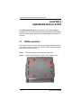
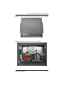

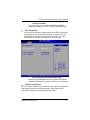
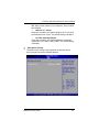
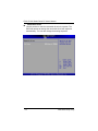
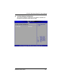
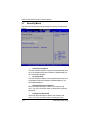
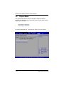
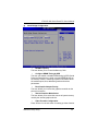
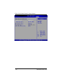
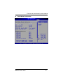
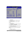
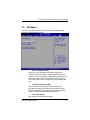
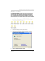
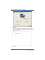


![[U4.22.01] Opérateur DEFI_GROUP](http://vs1.manualzilla.com/store/data/006355074_1-4d718b3e611764055ebba019faad5ff6-150x150.png)