1
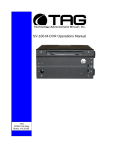
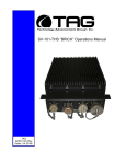
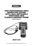
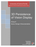
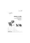
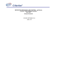
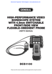
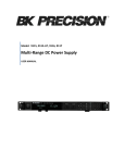
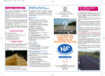
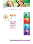
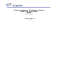
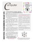
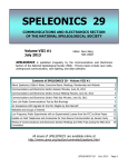
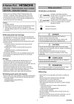
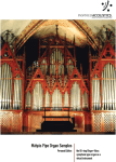
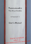
XV International PhD Workshop
OWD 2013, 19–22 October 2013
Development of a custom retro game console
Nóra Haláchy BSc student, Viktor Devecseri PhD student, Péter Korondi DSc,
Budapest University of Technology and Economics
Abstract
In this paper the development of a complex
mechatronic product through the example of a
custom retro game console including the integration
of the electronic components, programming, and
manufacturing is presented. There is an overview
and a comparison of the available components. As a
result of this comparison the best components can
be chosen to the game console. Through the
explanation of the functional block diagram the
functionality of the device can be easily explained.
Beyond the electrical part a minimal framework for
game and application programming is presented.
Finally some highlights about how an idea evolved
into a real product through design and construction
is shown.
system on a chip, which includes an ARM 700 MHz
processor. Model B has 512 MB of RAM, it uses an
SD card for booting and long term storage.
1. Intro
Fig. 1. Raspberr y Pi (Mod el B)
Recently, the goal for the manufacturers of the
games is to achieve maximum gaming experience
using maximum technical parameters. Now games
can be played in 3D, or in very high resolution,
which results in very realistic games, but we think the
maximum gaming experience doesn’t depend on the
technical parameters. In opinion, the gameplay is up
to the game’s atmosphere.
In spirit of this our product was developed, and
the goal was to provide classic games such as Snake.
Simple games, but unique gaming experience is
guaranteed.
This product is completely developed by us, and
consists of a game controller, an 8x10 LED matrix,
and a central logic unit. This kind of game controller
can’t be found commercially.
1.1
Available components
Choosing the right microcontroller was the first
step, because this can strongly influences the course
of the development and the outcome too. Taking
into account the project’s specialties three boards are
found to be suitable for the final construction.
1.1.1
Raspberry Pi (Model B)
The Raspberry Pi is a credit card sized singleboard computer (Fig. 1.), has a Broadcom BCM2835
It has 8 GPIO pins, +5V, +3,3V, ground, but
even if the 700MHz [1] clock speed is amazing, the 8
GPIO pins is not enough for this project. The
TLC5940 LED driver needs 5 pins, and one
controller has at least 4 pushbuttons. Connecting
more than one controller to the Raspberry Pi is
harder because the number of available GPIO pins.
The Raspberry Pi can run different operation
systems for free, such as Linux, Raspbian. For
prototyping another board can be more efficient
without an operation system.
1.1.2
PIC boards
EasyPIC boards were equipped with PIC16 chip
[3], but this new version (EasyPIC v7) is equipped
with PIC18. It has 16 MIPS operation, 64K bytes of
linear program memory, 3896 bytes of linear data
memory, and support for a wide range of power
supply from 1.8V to 5V. It’s loaded with great
modules: 36 General purpose I/O pins, 30 Analog
Input pins (AD), Digital-To-Analog Converter
(DAC), support for Capacitive Touch Sensing using
Charge Time Measurement Unit (CTMU), three 8bit timers and four 16-bit timers. It also has pair of
CCP, Comparators and MSSP modules (which can
be either SPI or I2C).
302
assist the development. On the other hand, there are
plenty of pins to use, and this structure of the
hardware and software is ideal for this type of
prototyping.
Tab. 1.
Comparison of t he available boards
Arduino
Mega2560
Clock spd
RAM
Pins
Price
Fig. 2. Easy PIC v7
By using this board the developer has a bunch of
opportunity. In this board there is a built in Liquid
Chrystal Display, LEDs, buttons, 7-segment display,
and of course a lot of other sensors and output
devices (Fig.2.).
1.1.3
Arduino
Arduino is an open-source electronics
prototyping platform based on flexible, easy-to-use
hardware and software. It's intended for artists,
designers, hobbyists and anyone interested in
creating interactive objects or environments.
16 MHz
256 Kb
54
39 EUR
PIC
EasyPIC
v7
20 MHz
64 Kb
36
113 EUR
Raspberry
Pi Model B
700 MHz
256 Mb
14
27 EUR
Now, we know which will be the brain of the
game controller, let’s see the other parts. The other
main parts are presented on Fig. 4.
In the second chapter the details of the electrical
part will be shown, including the hardware. In the
third chapter the software part will be discussed, and
then in the fourth chapter the physical
implementation of the construction will be
presented. In the end there will be a short summary
of the whole project.
Controller
Arduino
LED driver
LED matrix
Fig. 4. Overview
2. Electronics
On Fig. 5 the functional block diagram is shown.
The controlling unit is an Arduino board, which is
controlling the LED drivers. In contrary the
illustration, there are 5 LED drivers in the real
circuit.
Fig. 3. Arduino Mega 2560
The microcontroller on the board is programmed
using the Arduino programming language (based on
Wiring) and the Arduino development environment
(based on Processing). Arduino projects can be
stand-alone or they can communicate with software
running on a computer (e.g. Flash, Processing).
One of the most popular boards is the Arduino
Mega 2560 (Fig. 3.). It has 54 digital I/O pins [2], of
which 15 provides PWM, 16MHz clock speed, and
256 KB flash memory.
1.2
Conclusion
As in the previous sections it has also been
presented, these boards provide a very wide range of
opportunities for technical terms (Tab. 1.). To make
this into a successful project, appropriate software,
and support is required too. Thus, the choice have
fallen on the Arduino board, because of the existing
libraries, discussion forums, sample programs to
Fig.5. The fu nctional block diagram of t he s yst em
The TLC 5940 (Fig. 6.) is a 16 channel constantcurrent sink LED driver. It has a 12 bit (4096 steps)
grayscale PWM control, and a 6 bit (64 steps) dot
303
correction. LED power supply voltage is up to 17 V,
communicates via Serial Data Interface [4].
NT PACKAGE
(TOP VIEW)
OUT1
1
28
OUT0
OUT2
2
27
VPRG
OUT3
3
26
SIN
OUT4
4
25
SCLK
OUT5
5
24
XLAT
OUT6
6
23
BLANK
OUT7
7
22
GND
OUT8
8
21
VCC
OUT9
9
20
IREF
OUT10
10
19
DCPRG
OUT11
11
18
GSCLK
OUT12
12
17
SOUT
OUT13
13
16
XERR
OUT14
14
15
OUT15
control the LED driver. The LED matrix library
controls the LEDs through the TLC library.
The Controller library makes easier to get
information about each button’s state. Using a
pushbutton the bounce button phenomenon needs
to be avoided. With the controller library the button
state is only a boolean variable, which value is
debounced by processing the button events.
3.1.
Fig. 6. Chann els of th e LED dr iver [4 ]
This device makes it possible to control 16 LEDs
using 5 pins (not counting the VCC and GND) in
the Arduino board. It’s possible to chain these
drivers if more than one is needed. In this case the
number of requested pins on the Arduino is not
increasing, but the number of the connected LEDs
are increased.
The controller contains 8 pushbuttons, and one
LED for checking the connection with the Arduino
board. This LED is turned on, if the controller is
connected to the board.
For the LED matrix we used blue 3 mm LEDs.
Luminous intensity is between 3000 and 4000
millicandelas. The beam angle is 20°, so one LED’s
luminous flux can be easily calculated. The number
of lumens (lm) per LED is 0,38.
Game logic
After the initialization the game’s main loop
starts. The first task is to check the input via the
Controller library. If there is any input, the program
handles it, and the internal state of the game is
updated. If there isn’t any event from the user, the
game’s internal state will be also updated (for
example the snake is moving forward naturally
without interruption). Then the display will be
refreshed, which means that the output (the LED
matrix) will be physically refreshed, and the internal
state will be the same as the external.
4. Physical implementation
The main material of the body and the controller
is wood. On Fig. 8 one moment of the Snake game
is shown. Behind the white plastic planes there are
blue LEDs. Owing to the small white plastic planes,
each LED provides a homogenous, diffuse light. At
the bottom there is an “N” character. This is lighten
if the game controller is switched on, and it’s dark, if
it’s switched off. This is a feedback to the user and a
design element too.
3. Software
Hardware
Software
On Fig 7. the software architecture is shown. The
darker cells are implemented by us, and the white
cells are open source components.
Fig 8. Main body concept
Fig. 7. The archit ectur e of th e software
To use the hardware of Arduino, Wiring gives an
easy to use Object Orientated interface (for example
easier handling of pins, timers, PWM etc.).
The TLC library hides the details of the SDI
communication, and provides a simpler interface to
304
not in use. Furthermore built in speakers, and sound
effects can increase the gaming experience.
6. Bibliography
[1] Raspberry Pi: http://www.raspberrypi.org/, the
official page of the Raspberry Pi
[2] Arduino:
Official
Arduino
page,
http://www.arduino.cc
[3] Mikroelektronika: EasyPIC v7 user manual,
http://www.mikroe.com
[4] Texas Instruments: TLC5940NT datasheet,
http://www.ti.com/lit/ds/symlink/tlc5940.pdf
[5] Efunda: Laminated Object Manufacturing,
http://www.efunda.com/processes/rapid_prot
otyping/lom.cfm
Fig. 9. Controller conc ept
The controller (Fig. 9.) is made with LOM
(Laminated Object Manufacturing). This is a rapid
prototyping system [5]. First the appropriate shape
must be cut. The body is divided by layers. In one
step only one layer can be made, so the whole body
will be ready, if the layers are glued together
successfully. For cutting the layers we used a laser
cutter machine. Then the layers need to be skived
together, so this way the edges of the individual
layers can be hided.
Authors:
Nóra Haláchy
Budapest
University
and
Technology and Economics
Bertalan Lajos Street 4-6
1111 Budapest
tel. +36 1 463-2602
fax +36 1 463-3787
email: [email protected]
MSc. Viktor Devecseri
Budapest University and
Technology and Economics
Bertalan Lajos Street 4-6
1111 Budapest
tel. +36 1 463-2602
fax +36 1 463-3787
email: [email protected]
Fig. 10. The display with th e controller
The main body’s physical size will probably
approach an average television (Fig. 10.), but not
with 16:9 aspect ratio, it’s around 4:3. The controller
is almost the same size with the other existing game
controllers in the market.
5. Summary
This project needed a lot of knowledge and
experience from different areas, and it’s started
totally from zero. In a few weeks from blueprints,
and schematics it’s became something real,
something concrete.
The point was to make something simple, but
giving high gaming experience. We reached our goal
and we hope other people will enjoy this game too.
In the future we’d like to make a little bit bigger
display with RBG LEDs, and make the body
foldable, and saving place, when the game console is
305
DSc. Péter Korondi
Budapest
University
Technology and Economics
Bertalan Lajos Street 4-6
1111 Budapest
tel. +36 1 463-2602
fax +36 1 463-3787
email: [email protected]
and