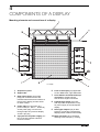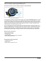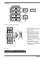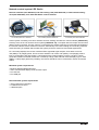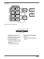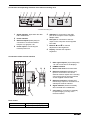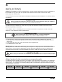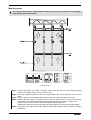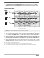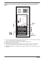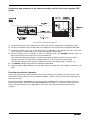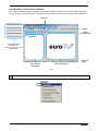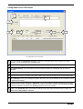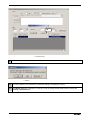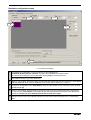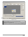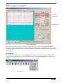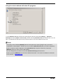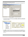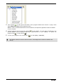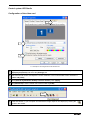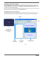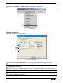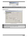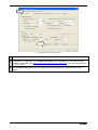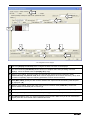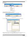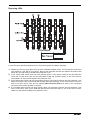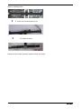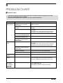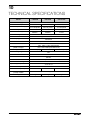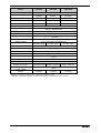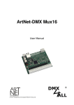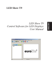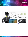
1
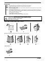
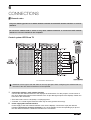
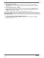
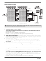
MKII
USER MANUAL
www.eurolite.de
LSD LED SOFT DISPLAYS ECO
• Inexpensive economy version of the successful LED soft displays
• Flexible displays with tri-color RGB LEDs (type SMD 3528) for bright and colorful projection of videos and graphics
• Modular display concept allows the build-up of large areas, ideal for outdoor use with large viewing distances
• Bendable and foldable PVC material suitable for various shapes, e.g. columns, circles, angles
• Proven connector system with push buttons and hook-and-loop connections
• Fast and uncomplicated installation, indoor and outdoor (IP 44)
• Truss suspension via built-in belts
• Water-repellent and flame-resistant
• Low weight and small volume for convenient transport
• Easy maintenance - LEDs can be replaced without difficulty
• Controllable via optional network components and PC software
• All-in-one control system T9 (80503300): network interface and software LED Show T9 - ideal system for mobile use with notebooks
with 1-gigabit NIC
• Control system LED studio: receiver interface (80503311), PCI sending card and software LED Studio (80503130)
• Recommended media software: MADRIX
• Switch-mode power supply for operation between 100 and 240 Volts
• Power output for passing on the power supply
• Available in different sizes and pixel pitches
• Custom sizes available upon request
..............................................................................................................................................................................
TABLE OF CONTENTS
INTRODUCTION ................................................................................................................................................3
SAFETY INSTRUCTIONS .................................................................................................................................4
OPERATING DETERMINATIONS .....................................................................................................................5
COMPONENTS OF A DISPLAY ........................................................................................................................6
MOUNTING ......................................................................................................................................................12
CONNECTIONS ...............................................................................................................................................15
INSTALLATION AND CONFIGURATION OF THE CONTROL SYSTEMS ...................................................21
CLEANING AND MAINTENANCE ..................................................................................................................39
PROBLEM CHART ..........................................................................................................................................44
TECHNICAL SPECIFICATIONS......................................................................................................................45
www.eurolite.de
2
1
INTRODUCTION
Thank you for having chosen a EUROLITE product. If you follow the instructions given in this manual, we are
sure that you will enjoy this device for a long period of time. Please keep this manual for future needs.
CAUTION!
Keep this device away from rain and moisture!
>>
For your own safety, please read this user manual carefully before you initially start-up.
This user manual is valid for the article numbers 80503270, 80503275, 80503274, 80503273,
80503272, 80503271. You can find the latest update at: www.eurolite.de
Every person involved with the installation, operation and maintenance of this device has to
- be qualified
- follow the instructions of this manual
- consider this manual to be part of the total product
- keep this manual for the entire service life of the product
- pass this manual on to every further owner or user of the product
- download the latest version of the user manual from the internet
Underlying information and preparation
LED Show T9
For this user manual, [LED Show T9] was used with [Version 10.48].
Please have the installation DVD at hand which comes with the all-in-one network control system. The DVD
includes the:
• installation file [Eurolite_LEDShow_10.48_Installer.exe]
• configuration file [EUROLITE_Default_Presets_T9.DAT]
• software's user manual [Version 10.48]
These files are also available for download:
• [Eurolite_LEDShow_10.48_Installer.exe]: http://download.showtechnic.de/?id=00053163
• [EUROLITE_Default_Presets_T9.DAT]: http://download.showtechnic.de/?id=00049488
• Software's user manual [Version 10.48]: http://download.showtechnic.de/?id=00055872
LED Studio
For this user manual, [LED Studio] was used with [Version 10].
The software's user manual comes with the network control system (item 80503130 or 80503309).
Please have the installation DVD at hand which comes with the respective network control system. The DVD
includes the:
• installation file [LEDStudio10.exe]
• configuration files in RCG formats (e.g. [112x128.RCG])
These files are also available for download:
• [LEDStudio10.exe]: http://download.showtechnic.de/?id=00061373
• RCG configuration files: http://download.showtechnic.de/?id=00049489
• Software's user manual [Version 8.26]: http://download.showtechnic.de/?id=00049519
www.eurolite.de
3
2
SAFETY INSTRUCTIONS
CAUTION!
Be careful with your operations. With a dangerous voltage you can suffer a dangerous
electric shock when touching the wires!
This device has left our premises in absolutely perfect condition. In order to maintain this condition
and to ensure a safe operation, it is absolutely necessary for the user to follow the safety
instructions and warning notes written in this user manual. Damages caused by the disregard of this
user manual are not subject to warranty. The dealer will not accept liability for any resulting defects
or problems.
Taking into Operation
Please make sure that there are no obvious transport
damages. Should you notice any damages on the
power unit or on the casing, do not take the device into
operation and immediately consult your local dealer.
If the device has been exposed to drastic temperature
fluctuation (e.g. after transportation), do not switch it on
immediately. The arising condensation water might
damage your device. Leave the device switched off until
it has reached room temperature.
operation, disconnected and then be cleaned with a dry
cloth. Dust can reduce the insulation which may lead to
mortal electrical shock. More severe dirt in and at the
device should only be removed by a specialist.
Liquid and Objects
There must never enter any liquid into power outlets,
extension cords or any holes in the housing of the
device. If you suppose that also a minimal amount of
liquid may have entered the device, it must immediately
be disconnected. This is also valid, if the device was
exposed to high humidity. Also if the device is still
running, the device must be checked by a specialist if
the liquid has reduced any insulation. Reduced
insulation can cause mortal electrical shock. There
must never be any objects entering into the device. This
is especially valid for metal parts. If any metal parts like
staples or coarse metal chips enter into the device, the
device must be taken out of operation and disconnected
immediately. Malfunction or short-circuits caused by
metal parts may cause mortal injuries.
Protection Class
This device falls under protection class II and features a
protective insulation. The voltage and frequency must
exactly be the same as stated on the device. Wrong
voltages or power outlets can lead to the destruction of
the device and to mortal electrical shock..
Power Cord
Always plug in the power plug least. The power plug
must always be inserted without force. Make sure that
the plug is tightly connected with the outlet. Never let
the power cord come into contact with other cables!
Handle the power-cord and all connections with the
mains with particular caution! Never touch them with
wet hands, as this could lead to mortal electrical shock.
Never modify, bend, strain mechanically, put pressure
on, pull or heat up the power cord. Never operate next
to sources of heat or cold. Disregard can lead to power
cord damages, fire or mortal electrical shock. The cable
insert or the female part in the device must never be
strained. There must always be sufficient cable to the
device. Otherwise, the cable may be damaged which
may lead to mortal damage. Make sure that the power
cord is never crimped or damaged by sharp edges.
Check the device and the power cord from time to time.
If extension cords are used, make sure that the core
diameter is sufficient for the required power
consumption of the device. All warnings concerning the
power cords are also valid for possible extension cords.
Children and Amateurs
Keep away children and amateurs! Never leave this
device running unattended.
Maintenance and Service
There are no serviceable parts inside the speaker
system. Maintenance and service operations are only to
be carried out by authorized dealers!
Cleaning
Always disconnect from the mains, when the device is
not in use or before cleaning it. Only handle the power
cord by the plug. Never pull out the plug by tugging the
power cord. Otherwise, the cable or plug can be
damaged leading to mortal electrical shock. If the power
plug or the power switch is not accessible, the device
must be disconnected via the mains. If the power plug
or the device is dusty, the device must be taken out of
www.eurolite.de
4
3
OPERATING DETERMINATIONS
The flexible displays of the LSD series were specially designed for projection of videos and graphics
synchronous to the computer. The inexpensive economy version is equipped with tri-color RGB LEDs type
SMD 3528. The dispalys are made of bendable and foldable PVC material and can be easily suspended
from truss systems. The modular design allows the horizontal and vertical built-up of video screens, indoor
and outdoor. Control is via special PC software and network components (optionally available).
Modifications and Guarantee
Please consider that unauthorized modifications on the
speaker system are forbidden due to safety reasons! If
this speaker system will be operated in any way
different to the one described in this manual, the
product may suffer damages and the guarantee
becomes void. Furthermore, any other operation may
lead to dangers like crashes, hearing loss etc.
Power
This product is only allowed to be operated with the
voltage given on the type plate.
IP Rating
This device is splash-proof (IP 44) and therefore
qualified for indoor and outdoor use. For outdoor use,
the installer must always make sure to connect a rubber
cable HO5RR-F. All valid instructions concerning the
installation of cables outdoors or in the ground must be
adhered.
Installation
Do not shake the device. Avoid brute force when
installing or operating the device. Before installing the
system, make sure that the installation area can hold a
minimum point load of 4 times the system's load (e.g.
weight 20 kg - point load 80 kg). For overhead use
(mounting height >100 cm), always secure the
installation with an appropriate secondary safety
element (e.g. steel rope). Make sure the area below the
installation place is cordoned off when rigging,
derigging or servicing the device. Do not connect
displays to the mains while they are folded.
Ambient Conditions
The ambient temperature must always be between -10°
C and +45° C. Keep away from direct insulation
(particularly in cars) and heaters. The maximum relative
humidity is 100 % with an ambient temperature of 25°
C. This device must only be operated in an altitude
between -20 and 2000 m over NN. The F-symbol
means: this device can be installed on normal
- - -m
inflammable surfaces. The symbol
determines the minimum distance from lighted objects.
The minimum distance between light output and the
illuminated surface must be more than the given value.
The maximum ambient temperature Ta must never be
exceeded.
Taking into Operation
Operate the device only after having familiarized with its
functions. Do not permit operation by persons not
qualified for operating the device. Most damages are
the result of unprofessional operation!
Cleaning and Storage
Never use solvents or aggressive detergents in order to
clean the device! Rather use a soft and damp cloth.
Serial Barcode
Never remove the serial barcode from the device as this
would make the guarantee void.
Transport
Please use the original packaging if the device is to be
transported.
www.eurolite.de
5
4
COMPONENTS OF A DISPLAY
Mounting elements and connections of a display
4-1 Display
1
2
3
4
5
Suspension point
6
Front of the display, equipped with
tri-color RGB LEDs, type SMD 3528
7
Press buttons and hook-and-loop
connectors, models LSD-25,
LSD-20 have angled connectors
8
Feed-through output (2-pin jack
with cap under the protective cover)
for power supply of the subsequent
display
9
Data signal outputs (15-pin DIN
jacks) for connecting a subsequent
display (number varies for each model)
Support bar
Data signal inputs (15-pin DIN
plugs) for connection to the AIO
network interface/receiver interface or
the previous display (number varies
for each model)
Power cable for connection to a
power outlet (90 - 260 V ~, 50/60 Hz)
via the power plug or to the feedthrough output of a previous display
via the 2-pin plug
10 Belts with hook, have combined
2-pin jack for the power supply (5 V
DC) of the AIO network interface/
receiver interface
www.eurolite.de
Working Load Limit (WLL) of 36 kg
6
All-in-one network control system LED Show T9
AIO network interface and control software LED Show T9 (item 80503300)
4-2 Included parts item 80503300
This complete set consisting of network interface and the control software [LED Show T9] allows for control
of the displays together with a Windows PC and a gigabit ethernet network card (1000 Mbps). This system
does not require a further video card with DVI output, which makes it ideally suitable for mobile use with a
notebook. The transmission of the data signals with a screen resolution of up to 1280 x 1024 pixels from the
computer to the network interface is done via the supplied network cable. If needed, a standard CAT5e
network cable up to 100 meters long may be used.
For connecting displays the network interface offers eight data signal outputs, each allows control of 128
(width) x 16 (height) pixels. So one network interface can control 128 (width) x 128 (height) pixels in total. A
configuration with 256 (width) x 128 (height) pixels is also possible, however, results in a lower grayscale
resolution and data refresh rate. To built-up a large video wall with several displays (up to 1280 (width) x
1024 (height) pixels are possible), the network interfaces can be connected in series via network cables.
Minimum system requirements
• Windows 2000/XP/Vista/7
• Dual-core CPU >1.8 GHz
• >1 GB disk space
• Separate gigabit ethernet connection (1000 Mbps)
• 1024 x 768 screen resolution
Recommended system requirements
• 2.9 GHz dual-core CPU
• 4 GB disk space
• Realtek network card with RTL chip
www.eurolite.de
7
Block diagram
4-3 Block diagram LED Show T9
Connections of the AIO network interface
4-4 AIO network interface
Pixel control
per data cable
per AIO network interface
www.eurolite.de
128 (width) x 16 (height) pixels
128 (width) x 128 (height) pixels
8
1
Data signal outputs (15-pin DIN jacks)
1 to 8 for connection to the displays
2
3
4
POWER indicator
5
Ethernet connection 1 (RJ45 jack),
input for connection to the ethernet
network output (1000 Mbps are
required) of a computer or the previous
AIO network interface via the supplied
network cable
6
Signal indicator, flashes constantly
when the data link is established
7
2-pin plug for connection to a display
for power supply (5 V DC) of the AIO
network interface
Button Test mode for function tests
Ethernet connection 2 (RJ45 jack),
feed-through output for connection to a
subsequent AIO network interface
Network control system LED Studio
Receiver interface (item 80503310) and PCI sending card (item 80503130) or external DVI sending
card (item 80503309), each with LED Studio control software
4-5 Included parts item 80503311
4-6 Included parts item 80503130
4-7 Included parts item 80503309
Control system consisting of receiver interface and PCI sending card with the control software [LED Studio].
Contrary to the all-in-one network control system [LED Show T9], a computer with DVI output card and dual
display mode is required. The DVI output is connected to the sending card DVI input and then transmitted to
the receiver interface via the ethernet connectors. Alternatively to the PCI sending card a sending card with
external housing is available which makes the system perfect for rental use and mobile applications.
For connecting displays the receiver interface offers eight data signal outputs, each allows control of
128 (width) x 16 (height) pixels. So one receiver interface can control 128 (width) x 128 (height) pixels in
total. A configuration with 256 (width) x 128 (height) pixels is also possible, however, results in a lower
grayscale resolution and data refresh rate. To built-up a large video wall with several displays (up to 1280
(width) x 1024 (height) pixels are possible), the receiver interfaces can be connected in series via network
cables.
Minimum system requirements
• Windows 98/me/2000/NT/XP/Vista
• Video card with dual display mode and DVI output
• Free PCI slot
• Free USB port
Recommended system requirements
• 1024 x 768 screen resolution
• 2.9 GHz dual-core CPU
• 4 GB disk space
www.eurolite.de
9
Block diagram
4-8 Block diagram LED Studio
Connections of the PCI sending card
4-9 PCI sending card
1
Status LEDs, red: power supply failure,
green: normal working mode
2
Gigabit ethernet outputs (RJ45 jacks)
for connection to a receiver interface
left jack = U, right jack = D
3
Input for power supply (5 V DC) from
an external source (optional accessory)
with low-voltage plug (center contact =
positive pole)
Only used if the sending card is
operated externally of a computer
www.eurolite.de
10
4
USB port for connection to the USB
port on the computer via the supplied
adapter cable
5
DVI input for connection to the DVI
output on the computer via the supplied
DVI cable
Connections and operating elements of the external sending card
4-10 External sending card
1
Signal indicator, lights when the data
link is established
2
Power indicator
3
Ethernet outputs (RJ45 jacks) for
connection to a receiver interface
left jack = U, right jack = D
4
Power input for connecting the
included power unit
5
USB port for connection to the USB
port on the computer via the supplied
adapter cable
6
DVI input for connection to the DVI
output on the computer via the supplied
DVI cable
7
Buttons
and
for manual
adjustment of the brightness
8
Display, indicates the adjusted
brightness
Connections of the receiver interface
4-11 Receiver interface
Pixel control
per data cable
per receiver interface
www.eurolite.de
128 (width) x 16 (height) pixels
128 (width) x 128 (height) pixels
11
1
Data signal outputs (15-pin DIN jacks)
1 to 8 for connection to the displays
2
3
4
POWER indicator
5
Ethernet connection 1 (RJ45 jack),
feed-through output for connection to a
subsequent receiver interface
6
Signal indicator, flashes constantly
when the data link is established
7
2-pin plug for connection to a display
for power supply (5 V DC) of the
receiver interface
Button Test mode for function tests
Ethernet connection 2 (RJ45 jack),
input for connection to one of the
ethernet network outputs of the sending
card or the previous receiver interface
via the supplied network cable
5
MOUNTING
Caution! For installation in public or industrial areas, a series of safety instructions have to be followed that
this manual can only give in part. The operator must therefore inform himself on the current safety
instructions and consider them.
The manufacturer cannot be made liable for damages caused by incorrect installations or insufficient safety
precautions!
DANGER TO LIFE!
Please consider the EN 60598-2-17and the respective national standards during the installation!
The installation must only be carried out by an authorized dealer!
The device has to be installed out of the reach of people and should be installed outside areas where
persons may walk by or be seated.
The installation area for the display has to be built and constructed in a way that it can hold 4 times the
weight for 1 hour without any harming deformation.
DANGER OF FIRE!
When installing the device, make sure there is no highly-inflammable
material (decoration articles, etc.) within a distance of min. 0.5 m.
The operator has to make sure that safety-relating and machine-technical installations are approved
• by an expert before taking into operation for the first time and after changes before taking into operation
another time.
• by an expert after every four year in the course of an acceptance test.
• by a skilled person once a year.
IMPORTANT! Overhead rigging requires extensive experience, including (but not limited to) calculating
working load limits, installation material being used, and periodic safety inspection of all installation material
and the device. If you lack these qualifications, do not attempt the installation yourself, but instead use a
professional structural rigger. Improper installation can result in bodily injury and or damage to property.
DANGER TO LIFE!
Before taking into operation for the first time, the installation has to be approved by an expert!
Allowed number of units connected on one suspension point
The allowed number of displays that can be connected in vertical direction and mounted on one suspension
point is limited. The combined Working Load Limit (WLL) of the belts of each model (including customized
sizes) is 36 kg. Use crossbars to set up larger display walls. The table below gives the maximum number of
units allowed for each model.
LSD-100E
LSD-75E
LSD-50E
LSD-37.5E
LSD-25E
LSD-20E
6
4
3
2
2
1
www.eurolite.de
12
Mounting steps
The supplied DVD includes a demonstration video which shows the installation of the displays:
[LSD Assembly Instructions.AVI].
5-1 Mounting steps
Step 1: Unpack the display and unfold it carefully. Place each belt with its hook pointing upwards
between the loops at the top of the protective cover.
Step 2: Insert the supplied support bar into the corresponding loops of the protective cover and the
belts.
Step 3: Loop the belts around suitable suspension point such as a truss and fasten the hooks.
Step 4: Models LSD-100, LSD-75, LSD-50, LSD-37.5: Use the press buttons and the hook-and-loop
connectors to connect several displays horizontally and vertically to built-up a large area.
Models LSD-25, LSD-20 can be connected via their angled connectors.
Additionally, fasten each hook on the belt of the lower display to the belt of the upper display.
Step 5: The length of the belts and thus the distance between the displays can be adjusted by sliding
the buckles.
www.eurolite.de
13
Disassembly
Step 1:
Step 2:
Step 3:
Step 4:
Disconnect all power connections and all data signal connections.
Loosen all push buttons and then all hook-and-loop connections.
Release all hooks and belts.
Take off the displays from the truss and put them with the back on the ground. You do not have
to pull out the support bars.
Step 5: The displays can either be folded or rolled. Always be careful and do not apply any pressure.
Do not bend the circuit boards but fold the displays in the spaces between the circuit boards. It
is best to store the displays in a case.
Two models are an exception:
• Model LSD-20 should be rolled only.
• Model LSD-18.25 should only be folded in half vertically.
EXTEND LIFE SPAN AND PREVENT DAMAGE!
• Always fold displays lengthwise with the surface face to face.
• Never fold crosswise or back to back.
• Do not bend circuit boards!
• Models LSD-100, LSD-75, LSD-50, LSD-37.5, LSD-25:
With larger models that must be folded several times, proceed as follows:
• Model LSD-20:
www.eurolite.de
14
6
CONNECTIONS
General notes
Only use cables type CAT-5e or better between network card and AIO network interface or receiver
interface.
Do not use a network hub or switch or any other network extension to connect the AIO network
interface or receiver interface to the computer.
Control system LED Show T9
6-1 Connections LED Show T9
Data flow is from right to left and starts on the top right part. When configuring the software later on,
the order of the AIO network interface must be specified.
1
Connection displays – AIO network interface
Connect the AIO network interface to the displays as shown above. For this purpose, connect each of
the 15-pin data signal outputs of the interface to the 15-pin data signal inputs of the displays: Fasten the
locknuts on the connectors.
•
•
2
Each data cable controls 128 (width) x 16 (height) pixels.
If needed, a 1.5 meter signal extension cable may be used (optional accessory).
Power supply AIO network interface
Power supply of the AIO network interface is via one the displays. Connect the 2-pin jack with the
indication [Connect to receiving controller] of one of the displays to the corresponding 2-pin jack of
the AIO network interface. Fasten the locknuts on the connectors.
www.eurolite.de
15
3
Connection display – display
Data signals can be relayed horizontally. For this purpose, connect each of the 15-pin data signal
outputs of a display to the 15-pin data signal inputs of the subsequent display. Fasten the locknuts on
the connectors.
4
Connection network interface – computer
Connect the AIO network interface to a computer. Connect the data signal input [Signal input] of the
interface to the gigabit ethernet port (RJ45 jack) of the computer via the supplied network cable. The
[SIGNAL] LED will be flashing constantly.
•
If needed, a standard CAT5e network cable up to 100 meters long may be used.
Only use a gigabit network card (1000 Mbps). Network cards with transfer rates of 100 Mbps or
less will not work.
5
Connection AIO network interface – AIO network interface
The network interface's output [Signal Transfer] serves for relaying the data signal to the [Signal
Input] on the next interface.
www.eurolite.de
16
Control system LED Studio
6-2 Connections LED Studio
Data flow is from right to left and starts on the top right part. When configuring the software later on,
the order of the AIO network interface must be specified.
1
Connection displays – receiver interface
Connect the receiver interface to the displays as shown above. For this purpose, connect each of the
15-pin data signal outputs of the interface to the 15-pin data signal inputs of the displays. Fasten the
locknuts on the connectors.
•
•
Each data cable controls 128 (width) x 16 (height) pixels.
If needed, a 1.5 meter signal extension cable may be used (optional accessory).
2
Power supply receiver interface
Power supply of the receiver interface is via one the displays. Connect the 2-pin jack with the indication
[Connect to receiving controller] of one of the displays to the corresponding 2-pin jack of the receiver
interface. Fasten the locknuts on the connectors.
3
Connection display – display
Data signals can be relayed horizontally. For this purpose, connect each of the 15-pin data signal
outputs of a display to the 15-pin data signal inputs of the subsequent display. Fasten the locknuts on
the connectors.
4
Connection receiver interface – PCI sending card or external sending card
Connect the receiver interface to the PCI sending card.
•
Prior to the connection, read section 6.4 which describes the procedure how to install the PCI sending
card.
Alternatively to the PCI sending card the receiver interface can also be connected to the external
sending card.
•
Prior to the connection, read section 6.5 which describes the connection of the external sending card to
a computer.
Connect the data signal input [Signal Input] of the receiver interface to one of the ethernet ports (RJ45
jacks) of the sending card via the supplied network cable. The [SIGNAL] LED will be flashing
constantly. Both jacks can be used as desired. When configuring the software later on, the jack used
must be specified: left jack = [U], right jack = [D].
•
If needed, a standard CAT5e network cable up to 100 meters long may be used.
www.eurolite.de
17
5
Connection receiver interface – receiver interface
The receiver interface's output [Signal Transfer] serves for relaying the data signal to the [Signal
Input] on the next interface. With [LED Studio], four receiver interfaces can be connected in series.
Connection to the mains
6-3 Example of power cabling
Caution! Do not connect displays to the mains while they are folded.
1
After having connected all components, connect the power plug of the first display to the mains (90-260
V AC, 50/60 Hz). The [POWER] indicator on the AIO network interface or receiver interface lights up
red.
2
For relaying the power supply, remove the cable part with the power plug on the power cables of the
subsequent displays. On all displays, pull out the feed-through cable marked [AC 90~260 V AC] from
protective cover and remove the protective caps.
3
Connect the feed-through output of the first display to the 2-pin plug on the power cable of the next
display etc. until you have connected a maximum of 5 displays. The next 5 displays must be connected
to the mains separately.
4
Make sure all connectors are locked firmly.
5
If needed, a 1.5 meter power extension cable may be used (optional accessory).
6
After operation, disconnect the displays from the mains and then loosen all cable connections.
www.eurolite.de
18
Installation and connection of the PCI sending card for the control system LED
studio
6-4 Installation of the PCI sending card
1 Turn off the computer, disconnect the power plug and remove the case. Take anti-static precautions
(e.g. touch a metal object) to avoid damage to the computer.
2 Insert the sending card into a free PCI slot of the computer. Replace the case.
3 Apply power to the computer and start it.
4 Connect the DVI and USB ports of the sending card to the computer's ports via the supplied cables.
The computer's graphics card must be configured for use with the sending card (➝ chapter 7.3).
5 If the green status LED of the sending card is flashing constantly, power supply and data link are
established.
www.eurolite.de
19
Connection and operation of the external sending card for the control system LED
Studio
6-5 Connection of the external sending card
1 Connect the DVI port of the sending card to the DVI port of the computer via the supplied DVI cable.
2 Connect the USB port of the sending card to the USB port of the computer via the supplied USB cable.
3 Connect the power supply unit to the power input jack [DC 5V] on the sending card and connect the
power cable to the power supply unit. Plug the mains plug to a mains outlet.
4 Thus the sending card is powered on and is in standby mode. The [POWER] indicator lights. By
disconnecting the unit from the mains it can be switched off.
Use only the included power supply unit. Always disconnect the mains connector when you wish to
change connections, move the unit to a different place or if it is not used for a longer period.
The computer's graphics card must be configured for use with the sending card (➝ chapter 7.3).
5 The [SIGNAL] indicator lights when the data link is established.
6 With the buttons [ ] and [ ] you can manually adjust the brightness of the displays connected in 16
steps.
Function test with the interfaces
After connecting the AIO network interface or the receiver interface to the displays, you can perform a first
functional test without having to run the respective software. Therefore you can check if all components are
connected correctly.
By pressing the button [Test mode] you can successively call different color and test programs which are
shown on the displays. Keep the button [Test mode] pressed for approx. 7 seconds to exit the test mode.
Please note that this mode is only applicable for color tests. There may be deviations when running
programs.
www.eurolite.de
20
7
INSTALLATION AND CONFIGURATION
OF THE CONTROL SYSTEMS
Depending on the control system, the matching PC program must be installed before taking the displays into
operation. This chapter is a quick guide for setting up both control systems. Please refer to the
corresponding user manuals for further information regarding installation, configuration and operation. The
manuals are included in the delivery and are also available for download on the internet.
As drivers and software are constantly being developed, your installation screens and procedures
may vary slightly from those described in this user manual.
Control system LED Show T9
Attention! Prior to installing the control software, make sure you have assigned a static IP address to
your computer, or use a separate network card for operating the control system [LED Show T9]. If
your computer does not have a static IP address or if the IP address is allocated via DHCP (Dynamic Host
Configuration Protocol), the control software LED Show T9 automatically assigns the IP address
192.192.192.111 and you can no longer access the network. The IP address remains assigned even after
closing the software so that you have to manually restore your original network settings in order to reaccess
the network.
Installation of the control software
Connect the displays as described under 6.1 and connect the AIO network interface to your computer. As
soon as an ethernet connection is established, the computer displays a dialog window in the lower right
corner of the screen (possibly limited connectivity is displayed, nevertheless, the ethernet connection is
sufficient for operation). The signal indicator on the AIO network interface will be flashing constantly.
Now install the control software [LED Show T9] on your computer. For this purpose, start the installation
program on the supplied DVD and follow the instructions of the installation program.
•
In order to install the control software you must log on to your computer as administrator or user with
administrator rights.
www.eurolite.de
21
Configuration of the control software
The control software must be configured for use with the displays, network card and AIO network interface.
For this purpose, start the program. The graphical user interface and the preview window will be displayed.
Menu bar
Toolbar
Toolbar
for programing
Preview window
The content is
synchronously displayed on
the displays
Software
status
Tree structure
of programs
Program paramters
7-1 GUI
> Call menu item [Control] ➝ [LED Admin] to start with the configuration.
www.eurolite.de
22
Configuration menu LED Admin
1
2
3
4
5
6
7
8
7-2 Configuration menu LED Admin
1 The control software [LED Show T9] allows control of a complete video wall (consisting of several
displays). Leave the default value for [LED] at [1].
2 Select the correct gigabit network card.
3 Click [NIC assistant]. The connection to the AIO network interface is established and its version is
indicated.
4 Enter the start position for the preview window on the computer monitor in fields [startx] and [starty].
5 Specify the size for the complete video wall in pixels: Enter width and height in the corresponding fields.
6 Click [Change] to store your settings for position and size. The preview window on the computer monitor
is adjusted accordingly.
7 The basic setting for the data path is [right-left]. If you have cabled the displays differently or the image
output is mirror-inverted, change the direction accordingly using the dropdown menu [direction (front)].
If you have made any changes, click [Change] again to store your settings.
8 Finally, click [parameter set]. The hardware settings for the AIO network interface will be called. The
dialog window [Key Input] is displayed.
www.eurolite.de
23
T9
7-3 Password entry
9 Now enter the admin password [T9]. Observe the correct spelling.
7-4 Dialog
10 You will be asked if you would like to customize settings. Click [Yes] to confirm.
11 The [Board Type] tab is displayed. In this tab, leave all settings at their default values. Select the
[receiver connection] tab.
www.eurolite.de
24
Hardware configuration menu
2
3
4
5
1
7-5 Tab [receiver connection]
1 To facilitate the configuration, use the preset file on the supplied DVD
[EUROLITE_Default_Presets_T9.DAT]. This file is also available for download under
http://download.showtechnic.de/?id=00049488. Click [Load] to load the preset file.
Note: Make a backup copy of this preset file.
2 Based on your cabling, enter the number of horizontal and vertical AIO network interfaces in fields [card
row] and [card col]. Now a field is displayed for each AIO network interface (➝ point 4).
3 As before in configuration menu [LED Admin], enter the start position on the computer monitor in fields
[to left] and [to up].
4 Based on your cabling, click the fields to specify the order of the AIO network interfaces. Alternatively,
you may use the field [number] on the right side. Set the first AIO network interface in the data path to
number [1]. Contrary to your cabling, the direction is from left to right.
5 Specify the size for each AIO network interface in pixels: Enter width and height in the corresponding
fields.
www.eurolite.de
25
6
7
7-6 Tab [receiver connection]
6 Transfer your settings to the AIO network interface by clicking [Send]. The progress bar is displayed.
The dialog [send complete] will inform you about the successful data transmission.
7 Click [Save] to store your personal settings in DAT format. Make sure you do not overwrite the original
preset file. Save the file under a different file name.
8 The configuration is now complete and you can close the [receiver connection] and [LED Admin] tabs.
www.eurolite.de
26
Manual adjustment of parameters
Frequency
Refresh rate
Gamma value
7-7 Tab [receiver param]
Some of the AIO network interface's parameters can be adjusted manually in the [receiver param] tab.
Generally, parameter do not require any adjustment thanks to the preset file loaded before. However, should
you notice irregular behavior of LEDs, you can correct errors in particular by adjusting the frequency and the
refresh rate.
Function test
For various function tests, call menu item [Debug]. Should you notice irregular behavior of LEDs, you can
correct errors by adjusting AIO network interface parameters in the [receiver param] tab (➝ see previous
section).
7-8 Function test
www.eurolite.de
27
Using the control software with other PC programs
7-9 [Caputre screen mode]
To use [LED Show T9] with another PC media program call menu menu item [Setting] ➝ [Software
Settings] and check [capture screen mode]. Please note that [LED Show T9] must remain active. You can
also e.g. deactivate the background in the preview window or the cursor display in this menu.
Notes
The lighting control software [MADRIX] features a DVI patch from version [2.12] for easy control and
configuration of LSD displays. Therefore you can do without [LED Show T9] after your initial configuration.
Please note that an initial configuration under [LED Show T9] is required nevertheless. Otherwise
[MADRIX] cannot be used to control LSD displays.
You can disregard the procedure in menu item [Software Settings] describe above.
Please consult the [MADRIX] user manual for detailed information. The manual is available for download
on the internet ➝ www.madrix.com.
www.eurolite.de
28
Testing LED Show T9 and playing a video file
You can project videos and graphics in all popular formats on your LSD displays. Some example files come
with the supplied DVD.
7-10 Creating a program
1 At first, create a new program. In the toolbar, click symbol [
] and [Blank Page]. [Normal Page1]
will be displayed in the tree structure. In the right section, different attributes such as name, background
and duration can be adjusted.
2 Click [
] or the right mouse button to create a new program window. Select [File Window] in the
dropdown menu. A program can consist of multiple program windows. A program window can extend
over the entire video wall or just a section. You can specify the position and size of a window by
dragging the mouse in the preview window or enter them among other basic attributes in the [Window
Attr.] section.
www.eurolite.de
29
3 Click symbol [
] or the right mouse button to fill a program window with contents. To play a video
select [Add Video files] from the dropdown menu.
Note: In order to create MS Office files with the software, the respective applications must be installed
on your computer.
4 Load the desired video file and click symbol [
preview window on your computer monitor and
], to stop it click [
].
program click [
5 To save your program in CLT format click [
] in the toolbar. The video will be displayed in the
synchronously on your displays. To pause the
] or select [File] ➝ [Save As].
The software features numerous other functions. A full-fledged user manual is included in the
delivery.
www.eurolite.de
30
Control system LED Studio
Configuration of the video card
1
2
3
7-11 Example for the configuration under Windows XP
1 For [LED Studio] it is necessary to activate the second output of your video card. Go to [Control Panel]
➝ [Display Properties] and select the [Settings] tab.
2 Select the second monitor and adjust the screen resolution. The recommended screen resolution is
[1024 x 768 pixels].
3 Check [Extend my Windows desktop onto this monitor]. Click [Apply].
4 Click [Advanced] to set the refresh rate of the monitor to [60 Hz].
5
5 Install LED Studio on your computer and activate the image output on the displays by clicking the [
symbol in the toolbar.
www.eurolite.de
31
]
Installation of the control software
After completing the data cabling of the displays and establishing an ethernet connection, install the control
software [LED Studio] on your computer. For this purpose, insert the supplied DVD into your drive. The
installation start window will be displayed. Select [English] and [Installing LED play software] and follow
the instructions of the installation program.
Note: The DVD starts running automatically if auto start mode is enabled for your drive. If this is not the case
open the DVD and start the installation program [LEDStudio10.exe].
Configuration of the control software
The control software must be configured for use with the displays, sending card and network interface. For
this purpose, start the program. The graphical user interface and the preview window will be displayed.
Menu bar
Toolbar
Preview window
The content is
synchronously displayed on
the displays
Toolbar
for programing
Program paramters
Tree structure
of programs
7-12 GUI
www.eurolite.de
32
> Call menu item [Option] ➝ [Software Setup] to start with the configuration.
7-13 Software Setup
Software parameters
The software configuration menu is shown:
1
3
2
4
7-14 Software configuration menu
1 The control software [LED Studio] allows control of a complete video wall (consisting of several
displays). Leave the default value for [LED Numb] at [1].
2 In the [Play Window] tab, enter the start position for the preview window on the computer monitor in
fields [Start X] and [Start Y].
3 Specify the size for the complete video wall in pixels: Enter width and height in the corresponding fields.
4 Check [Alwayon top] if you do not want the preview window to be superimposed by other applications.
5 After your settings, type the password [linsn] on the keyboard. Observe the correct spelling. Notice there
is no field or indication on the screen.
www.eurolite.de
33
7-15 Password entry
6 The dialog window for password entry is displayed. The password is [168]. Click [Ok].
Hardware Parameters
If you have entered the correct passwords, the following hardware configuration menu is displayed:
1
2
7-16 Configuration of the sending card
1 Select the [Sender] tab and enter the computer monitor's screen resolution under [Display Mode]
(➝ 7.3.1).
2 Transfer your settings to the sending card by clicking [Save on sender].
Note: If the LED displays' brightness suddenly dims without any reason, restore all default settings: click
[Default] and [Save on sender].
www.eurolite.de
34
1
3
7-17 Configuration of the receiver interface
1 Select the [Receiver] tab to configure the receiver interface.
2 To facilitate the configuration, use the [RCG preset files] on the supplied DVD. These files are also
available for download under http://download.showtechnic.de/?id=00049489. Store and extract the files
on your computer.
3 Click [Load from Files] and select the configuration file that matches the output resolution of the
displays.
www.eurolite.de
35
1
2
3
3a
5
4
8
6
7
8
7-18 Configuration of the displays
1 Select the [Display Connection] tab to configure the data connection to the displays.
2 The control software [LED Studio] allows control of a complete video wall (consisting of several
displays). Leave the default value for [Display QTY] at [1].
3 Based on your cabling, enter the number of horizontal and vertical receiver interfaces in fields
[Horizontal card] and [Vertical card]. Now a field is displayed for each receiver interface (➝3 a). Click
the fields to separately adjust the following parameters of each receiver interface.
4 Under [Main cable], specify for each receiver interface the output used at the sending card: left jack =
[U], right jack = [D].
5 Based on your cabling, specify the order of the receiver interfaces under [Order No.]. Set the first
receiver interface in the data path to number [1].
6 Specify the size for each receiver interface in pixels: Enter width and height in the corresponding fields.
7 Transfer your settings to the receiver interface by clicking [Send to receiver].
8 Click [Save to file] to store your personal settings in RCG format. Make sure you do not overwrite the
original preset file. Save the file under a different file name.
www.eurolite.de
36
Function test
For various function tests, select menu item [Test].
7-19 Function test
Testing LED Studio and playing a video file
You can project videos and graphics in all popular formats on your LSD displays.
7-20 Programming mode
1 Click the [
] symbol in the toolbar to display the tools and fields required for programming.
7-21 Creating a program
2 First, create a new program by clicking [
]. [Step1] will be displayed in the tree structure. In the
right section, different attributes such as name, background and duration can be adjusted.
www.eurolite.de
37
7-22 Creating a program window
3 Click [
] to create a new program window. Select [File Window] in the dropdown menu. A program
can consist of multiple program windows. A program window can extend over the entire video wall or just
a section. You can specify the position and size of a window by dragging the mouse in the preview
window or enter them among other basic attributes in the right section.
4 To fill a program window with contents, click [
] and specify the path of your file. Below, you can
adjust different parameters depending on the file type, including background, position, text, play time and
effects. If you want to apply the parameters adjusted to all files in this program window, click [
].
5 To save your program in CLT format click [
] or select [File] ➝ [Save As...].
6 To play your program click [
] in the toolbar. The video will be displayed in the preview window on
your computer monitor and synchronously on your displays. To pause the program click [
], to stop
it click [
].
The software features numerous other functions. A full-fledged user manual is included in the
delivery.
www.eurolite.de
38
8
CLEANING AND MAINTENANCE
DANGER TO LIFE!
Disconnect from mains before starting maintenance operation!
We recommend a frequent cleaning of the device. Please use a soft lint-free and moistened cloth. Never use
alcohol or solvents!
Should you need any spare parts, please use genuine parts.
WARNING!
Maintenance and service operations are only to be carried out by authorized dealers!
Replacing a power adaptor
The power adaptors are located at the back of the displays and are connected in series.
www.eurolite.de
39
If the connectors are not properly connected or one of the adaptors is broken, the following situations may
occur:
1 If this power adaptor is broken the LEDs in the dashed are will not work.
2 If this power adaptor is broken the LEDs in the dashed are will not work.
www.eurolite.de
40
In case one of the situations occurs, follow these steps:
1 Disconnect all displays from mains power.
2 Remove the rear protection cover.
3 Check if all connectors are fastened in the area where the LEDs are not working. Then reconnect the
4
5
displays to mains power for testing.
If the problem still persists use a multimeter to test whether the AC and DC output voltage is steady. If
there is not output voltage or unsteady voltage replace the power adaptor: Plug out the connectors at
both ends of the power adaptor and remove the broken the broken power adaptor from its pocket. Insert
a now power adaptor and fasten the connectors with their locknuts.
Make sure that the new power adaptor is correctly connected and reconnect the displays to mains power
for testing. Reattach the protective cover.
www.eurolite.de
41
Replacing LEDs
In case one of the following situations occurs check and replace the LEDs if necessary:
1 Replace the LED if a single pixel does not work or displays irregular colors. For this purpose, remove the
2
3
4
rear protection cover with a screw driver, take out the PCB with the LED and replace the broken LED
with a new one and solder it. Reattach the protection cover.
If one vertical LED column does not work properly (point 1 in the figure): Remove the rear protection
cover with a screw driver, take out the PCB with the LED and check the wiring. If one of the wires is
loose solder it on the PCB and reattach the protection cover.
If two vertical LED columns do not work properly (point 2 in the figure): Remove the rear protection cover
with a screw driver, take out the PCB with the LED and check the wiring. If none of the wires is loose or if
there is no short circuit, open the box marked [Data Processor Box] and check if the counterpart
connector on the PCB is properly connected.
If a horizontal LED row does not work properly (point 3 in the figure): Remove the rear protection cover
with a screw driver, take out the PCB with the LED and check the wiring. If one of the wires is loose,
solder it on the PCB and reattach the protection cover.
www.eurolite.de
42
Steps for replacing LEDs:
9
1 Screw out rear black plastic cover.
9
2 Solder the wires.
Should you have further questions, please contact your dealer.
www.eurolite.de
43
9
PROBLEM CHART
General notes
•
•
•
If the entire display is without image, make sure all network cable are properly connected.
Only use cables type CAT-5e or better.
Do not use a network hub or switch or any other network extension.
PROBLEM
Entire display
without image
Partially no
image
POSSIBLE CAUSE
Network cable between PC and
interface is not connected
appropriately.
Sending card or interface is out
of order.
System settings are wrong.
[LED Show T9]: Network card
is not connected appropriately.
[LED Studio]: DVI cable is not
connected to sending card.
Monitor under Windows is not
activated or image output in
[LED Studio].
System settings are wrong.
REMEDY
Check the network cable connection and change
cable if necessary.
Check if the sending card and interface are correctly
installed.
Reconfigure the control software and your computer if
necessary.
Reconfigure the system with respective preset file.
Deinstall the control software and install it again.
Deactivate your firewall or network bridge.
Check the DVI connection.
Activate the monitor extension or image output.
Reconfigure the control software and your computer if
necessary.
Reconfigure the system with respective preset file.
Deinstall the control software and install it again.
Check the wiring of data processor to PCB.
Data processor at the back of
the display is without input or
output signal.
Display and interface are not
properly connected.
Power adaptor is broken.
Check the connectors, fasten the locknut again. Plug
and jack must be connected appropriately.
Replace power adaptor (➝8).
Single pixel is not
working
LED is broken
Replace LED (➝8).
LED row is not
working
Pixels are not properly wired.
Remove the rear protective cover of the display,
check the wiring of the LED row and renew it if
necessary. Reattach the protective cover (➝8).
Single pixels
react erratic
(e.g. shadows
under [LED
Show T9])
System settings are wrong.
Refer to section [Manual adjustment of parameters]
under [LED Show T9].
If the problem persists, contact your dealer.
www.eurolite.de
44
10
TECHNICAL SPECIFICATIONS
Model
LSD-20E
Power supply:
LSD-25E
LSD-37.5E
90 - 260 V AC, 50/60 Hz ~
Power consumption:
60 W/m²
40 W/m²
16 W/m²
Resolution (width x height):
64 x 128 pixels
48 x 64 pixels
32 x 64 pixels
Pixel pitch:
20 mm
25 mm
37.5 mm
Pixel density:
2500/m²
1600/m²
711/m²
Pixel configuration:
tri-color RGB LEDs, type SMD 3528
Lifetime:
approx. 100,000 hours
Display port:
DVI/RJ45
Control mode:
synchronous to video source
Drive mode:
1/8 scan
max. 1280 x 1024 (LED Studio)
max. 1024 x 896 (LED Show T9)
Screen resolution
(width x height):
Brightness:
940 cd/m² (nits)
585 cd/m² (nits)
260 cd/m² (nits)
Viewing angle:
120°
Frame rate:
60 Hz
Data refresh rate:
600 Hz
Colors:
16.7 million (R 256, G 256, B 256)
Protection rating:
IP 44
Operating temperature:
-10 to 45 °C
Humidity:
10 to 90 %
Dimensions (WxH):
Max. load WLL
(4-fold) of belts:
Weight:
www.eurolite.de
1280 x 2560 mm
1200 x 1600 mm
1200 x 2400 mm
36 kg
7.8 kg/m²
6.5 kg/m²
45
4 kg/m²
Model
LSD-50E
LSD-75E
Power supply:
LSD-100E
90 - 260 V AC, 50/60 Hz ~
Power consumption:
10 W/m²
4 W/m²
2.5 W/m²
Resolution (width x height):
32 x 48 pixels
16 x 32 pixels
16 x 16 pixels
Pixel pitch:
50 mm
75 mm
100 mm
Pixel density:
400/m²
177/m²
100/m²
Pixel configuration:
tri-color RGB LEDs, type SMD 3528
Lifetime:
approx. 100,000 hours
Display port:
DVI/RJ45
Control mode:
synchronous to video source
Drive mode:
1/8 scan
max. 1280 x 1024 (LED Studio)
max. 1024 x 896 (LED Show T9)
Screen resolution
(width x height):
Brightness:
150 cd/m² (nits)
75 cd/m² (nits)
40 cd/m² (nits)
Viewing angle:
120°
Frame rate:
60 Hz
Data refresh rate:
600 Hz
Colors:
16.7 million (R 256, G 256, B 256)
Protection rating:
IP 44
Operating temperature:
-10 to 45 °C
Humidity:
10 to 90 %
Dimensions (WxH):
Max. load WLL
(4-fold) of belts:
Weight:
1600 x 2400 mm 12600 x 2400 mm
1600 x 1600 mm
36 kg
2.5 kg/m²
2.2 kg/m²
1.8 kg/m²
*MADRIX is a trademark of inoage trade - Hertel, Pinzer, Wissmann GbR.
**Windows is a registered trademark of the Microsoft Corporation in the USA and other countries.
www.eurolite.de
46
www.eurolite.de
47
© EUROLITE 2014
Technische Änderungen und Irrtum vorbehalten.
Every information is subject to change without prior notice.
00085338.DOCX
Version 1.0