1
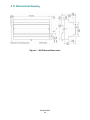
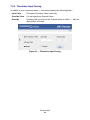
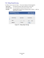
6.4 Pulse Inputs
A variation on contact closure inputs is pulse inputs. In this situation speed is critical so
the input filtering that limits the time response is removed. When an input is configured
for Pulse Input, a pulse rate up to 40 Hz can be measured, assuming a 50% duty cycle.
The pulse device could have an opto-isolated open-collector NPN transistor output
stage like the one identified under Contact Closure, or it could provide an active
sinusoidal output signal that needs to be detected. Data can be in the form of frequency
or pulse count.
The Pulse Input voltage range is 0–10 VDC and the installer can set both the lowthreshold and high-threshold on the Pulse Input web page. The difference in the two
thresholds is the hysteresis. You can detect sinusoidal input signals by setting the high
threshold below the positive peak and the low threshold above the negative peak.
Setting the two thresholds well toward the center of the sinusoidal waveform (rather than
near its peaks) offers some noise immunity. It is not necessary for the input signal to
swing from zero to 10 V. Any substantial swing within this range can be detected. The
input impedance using Pulse Input is 100 kΩ. Connect the output of the pulse device to
point A and the common to BAS Remote common as shown in Figure 10.
Figure 10 — Pulse Input Connections
The pulse output could be sinusoidal with no DC offset so the BAS Remote could
experience both positive and negative excursions of the signal. The BAS Remote can
only detect positive voltages so the negative excursions will be ignored. It is still
possible to detect the input signal by only sensing the positive excursions.
TD040300-0MC
23