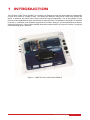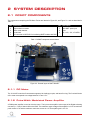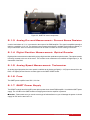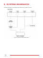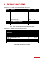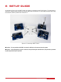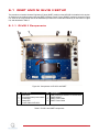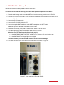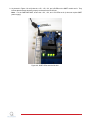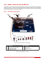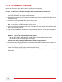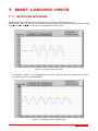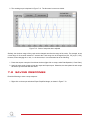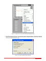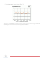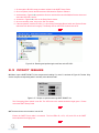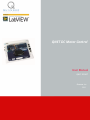
1
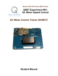
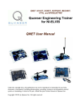
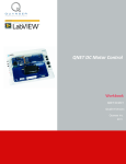
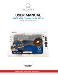
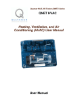
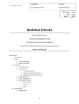
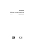
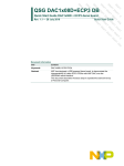
QNET DC Motor Control
User Manual
QNET DCMCT
Quanser Inc.
2011
c 2011 Quanser Inc., All rights reserved.
⃝
Quanser Inc.
119 Spy Court
Markham, Ontario
L3R 5H6
Canada
[email protected]
Phone: 1-905-940-3575
Fax: 1-905-940-3576
Printed in Markham, Ontario.
For more information on the solutions Quanser Inc. offers, please visit the web site at:
http://www.quanser.com
This document and the software described in it are provided subject to a license agreement. Neither the software nor this document may be
used or copied except as specified under the terms of that license agreement. All rights are reserved and no part may be reproduced, stored in
a retrieval system or transmitted in any form or by any means, electronic, mechanical, photocopying, recording, or otherwise, without the prior
written permission of Quanser Inc.
QNET DCMCT- User Manual
2
Contents
1
Introduction
4
2
System Description
2.1
DCMCT Components
5
5
3
System Schematic
7
4
Specifications
8
5
Environmental
9
6
Setup Guide
6.1
QNET and NI ELVIS II Setup
6.2
QNET and NI ELVIS Setup
10
11
14
7
QNET LabVIEW Hints
7.1
Scaling Scopes
7.2
Saving Response
16
16
17
8
Troubleshooting
8.1
General Software Issues
8.2
General Hardware Issues
8.3
DCMCT Issues
20
20
20
21
9
Technical Support
22
QNET DCMCT- User Manual
v 1.0
1
INTRODUCTION
The DC Motor Control Trainer (DCMCT) is a versatile unit designed to teach and demonstrate the fundamentals
of motor servo control in a variety of ways. The system can readily be configured to control motor position and
speed. In particular, the system can be used to teach PID control fundamentals. This is done using a PC with
real-time control capabilities and either the NI ELVIS I and the NI ELVIS II. The hardware of the DCMCT is described
in Section 2. A schematic of the hardware components is included in Section 3, and the specifications are listed in
Section 4 and Section 5. Some helpful LabVIEW hints when using the QNET VIs are given in Section 7 along with
a troubleshooting guide in Section 8.
Figure 1.1: QNET DC motor control trainer (DCMCT)
QNET DCMCT- User Manual
4
2
SYSTEM DESCRIPTION
2.1 DCMCT COMPONENTS
The components comprising the DC Motor Trainer are labeled in Figure 2.2, and Figure 2.3. and are described in
Table 1.
ID#
1
2
3
4
5
Description
DC Motor
High-resolution encoder
Motor metal chamber
Inertial load
PCI connector to NI ELVIS: for interfacing QNET module with DAC
ID#
6
7
8
9
Description
QNET PWM/Encoder board
24V QNET power jack
Fuse
+B, +15V, -15V, +5V LEDs
Table 1: DCMCT component nomenclature
Figure 2.2: General layout of QNET DCMCT
2.1.1 DC Motor
The 12-Volt DC motor has 5 commutator segments, 64 windings per pole, and has a flux ring. The Coulomb friction
of the motor corresponds to a voltage between 0.5 and 1.5 V.
2.1.2 Pulse-Width Modulated Power Amplifier
A PWM power amplifier is used to drive the motor. The input to the amplifier is the output of the Digital-to-Analog
converter (i.e. D/A) of channel #0 on the DAQ. The maximum output voltage of the amplifier is 24 V. Its maximum
peak current is 5 A and the maximum continuous current is 4 A. The amplifier gain is 2.3 V/V.
QNET DCMCT- User Manual
v 1.0
Figure 2.3: QNET DC motor components
2.1.3 Analog Current Measurement: Current Sense Resistor
A series load resistor of 0.1 Ω is connected to the output of the PWM amplifier. The signal is amplified internally to
result in a sensitivity of 1.0 V/A. The obtained current measurement signal is available at the Analog-to-Digital (i.e.
A/D) of channel #0. Such a current measurement can be used to monitor the current running in the motor.
2.1.4 Digital Position Measurement: Optical Encoder
Digital position measurement is obtained by using a high-resolution quadrature optical encoder. This optical encoder
is directly mounted to the rear of the motor. The encoder count measurement is available at Digital Input (i.e. DI)
channel #0 of the DAQ.
2.1.5 Analog Speed Measurement: Tachometer
An analog signal proportional to motor speed is available at the Analog-to-Digital (i.e. A/D) Input channel #4 on the
DAQ. It is digitally derived from the encoder signal on the QNET DCMCT board.
2.1.6 Fuse
The QNET power amplifier has a 250 V, 3 A fuse.
2.1.7 QNET Power Supply
The DCMCT module has a 24-Volt DC power jack to power the on-board PWM amplifier. It is called the QNET power
supply. The +B LED on the QNET board turns bright green when the amplifier is powered.
Caution: Please make sure you use the correct type of wall transformer or you will damage the system. It should
supply 24 VDC and be rated at 3.0 A.
QNET DCMCT- User Manual
6
3
SYSTEM SCHEMATIC
A schematic of the DCMCT system interfaced with a DAQ device is provided in Figure 3.4.
Figure 3.4: Schematic of QNET-DCMCT system
QNET DCMCT- User Manual
v 1.0
4
SPECIFICATIONS
The specifications of the DCMCT system model parameters are given in Table 2.
Symbol
Rm
Kt
Km
Jm
Ml
rl
VM AX
Description
Value
Unit
Motor:
Motor armature resistance
Motor current-torque constant
Motor back-emf constant (same as Kt in SI units)
Moment of intertia of motor rotor
Maximum continuous torque
Maximum power rating
Maximum continuous current
Inertial load disk mass
Inertial load disk radius
8.7
0.03334
0.03334
1.80 × 10⁻⁶
0.10
20.0
1.0
0.033
0.0242
Ω
N·m
V/(rad/s)
kg·m2
N·m
W
A
kg
m
Pulse-Width Modulated Amplifier:
PWM amplifier maximum output voltage
PWM amplifier maximum output current
PWM amplifier gain
24
5
2.3
V
A
V/V
Table 2: DCMCT model parameter and PWM power amplifier specifications
The specifications on the DCMCT system sensors are given in Table 3.
Description
Value
Unit
Current Sense:
Current Calibration
Current sense resistor
1.0
0.1
A/V
Ω
Motor Encoder:
Encoder line count
Encoder resolution (in quadrature mode)
Encoder type
Encoder signals
360
0.25
TTL
A,B
lines/rev
deg/count
Tachometer:
Tachometer calibration at QNET A/D input
2987
RPM/V
Table 3: DCMCT sensor parameter specifications
QNET DCMCT- User Manual
8
5
ENVIRONMENTAL
The DC motor control trainer environmental operating conditions are given in Table 4.
Description
Operating temperature
Humidity
Value
15 to 35
20 to 90
Unit
◦
C
%
Table 4: QNET DC motor control trainer environmental operating conditions
Caution: Ensure the unit is operated under the temperature and humidity conditions given in Table 4. Otherwise,
there may be some issues with the motion control results.
QNET DCMCT- User Manual
v 1.0
6
SETUP GUIDE
As illustrated in Figure 6.5, the QNET boards can easily be connected to an NI ELVIS system. The instructions in
Section 6.1 detail the setup procedure for using a QNET with an NI ELVIS II. For the setup procedure when using
the NI ELVIS I platform, please refer to Section 6.2.
Figure 6.5: Connecting a QNET Trainer
Caution: Do not position the ELVIS II so that it is difficult to disconnect the main power.
Caution: If the equipment is used in a manner not specified by the manufacturer, the protection provided
by the equipment may be impaired.
QNET DCMCT- User Manual
10
6.1 QNET AND NI ELVIS II SETUP
The procedure to install a Quanser Engineering Trainer (QNET) module on the NI ELVIS II is detailed in this section.
An example of an installed system using the QNET DC Motor Control Trainer (DCMCT) module is pictured in Figure
6.6. Some of the components used in the installation procedure are located and marked by an ID number in Figure
6.6, and described in Table 5.
6.1.1 ELVIS II Components
Figure 6.6: Components on ELVIS II and QNET
ID#
1
2
3
4
5
Description
NI ELVIS II
Prototyping board power switch
Power LED
Ready LED
Power Cable for ELVIS II
ID#
6
7
8
9
Description
USB Connection between PC and ELVIS II
QNET DCMCT
QNET Power LEDs
QNET Power Cable
Table 5: ELVIS II and QNET components
QNET DCMCT- User Manual
v 1.0
6.1.2 ELVIS II Setup Procedure
Follow these instructions to setup a QNET board on an ELVIS II:
Caution: Do NOT make the following connections while power is supplied to the hardware!
1. Place the small opening on the front of the QNET board over the mounting bracket on the NI ELVIS II.
2. Slide the PCI connector of the QNET module end into the female connector on the NI ELVIS II. Make sure it is
connected properly.
3. Connect the ELVIS II power cable.
4. Connect the ELVIS II USB cable to the PC.
5. Connect the supplied QNET transformer to the QNET power jack on the QNET module.
Note: Not required for the QNET mechatronic sensors trainer.
6. Power the NI ELVIS II by turning ON the System Power Switch on the rear panel.
7. Turn ON the Prototyping Board Power switch, ID #2 shown in Figure 6.6.
Caution: Turn OFF the Prototyping Board Power switch if
• On the QNET-DCMCT, QNET-ROTPENT, or QNET-VTOL Trainer the DC motor begins to turn
• On the QNET-HVACT the halogen light turns on brightly
Take extra care when powering the QNET module to avoid causing any damage!
8. The Power and Ready LEDs of the NI ELVIS II unit should be lit as shown in Figure 6.7.
Figure 6.7: Ready and Power LEDs on NI ELVIS II
QNET DCMCT- User Manual
12
9. As pictured in Figure 6.8, verify that the +15V, -15V, +5V, and +B LEDs on the QNET module are lit. They
indicate that the board has been properly connected to the ELVIS unit.
Note: For the QNET-MECHKIT, ensure the +15V, -15V, and +5V LEDs are lit (it does not require QNET
power supply).
Figure 6.8: QNET LEDs should all be ON
QNET DCMCT- User Manual
v 1.0
6.2 QNET AND NI ELVIS SETUP
The procedure to install a Quanser Engineering Trainer (QNET) module on the traditional NI ELVIS (ELVIS I) is
detailed in this section. An example of an installed system using the QNET DC Motor Control Trainer (DCMCT)
module is pictured in Figure 6.9. Some of the components used in the installation procedure are located and marked
by an ID number in Figure 6.9, and described in Table 6.
6.2.1 ELVIS Components
Figure 6.9: ELVIS and QNET setup components
ID#
1
2
3
4
Description
NI ELVIS Benchtop Workstation (ELVIS I)
Prototyping board power switch
Communications Switch
Power Cable for ELVIS I
ID#
5
6
7
Description
68-Pin E-Series or M-Series DACB Cable
QNET DCMCT
QNET Power Cable
Table 6: ELVIS and QNET components
QNET DCMCT- User Manual
14
6.2.2 ELVIS Setup Procedure
Follow these instructions to setup a QNET board on an traditional ELVIS (ELVIS I):
Caution: Do NOT make the following connections while power is supplied to the hardware!
1. Place the small opening on the front of the QNET board over the mounting bracket on the NI ELVIS (note that
some ELVIS workstations may not have mounting brackets).
2. Slide the PCI connector of the QNET module end into the female connector on the NI ELVIS. Make sure it is
connected properly.
3. Connect the NI ELVIS power cable shown as ID #4 in Figure 6.9.
4. Connect the QNET power cable labeled ID #7 in Figure 6.9.
Note: Not required for the QNET mechatronic sensors trainer.
5. Ensure the Prototyping Board Power switch, ID #2, is set to the OFF position and the Communications switch,
ID #3, is set to the BYPASS mode.
6. Power the NI ELVIS Benchtop Workstation by turning the Standby Switch on the rear panel of the system to
ON.
7. Turn ON the Prototyping Board Power switch.
Caution: Turn OFF the Prototyping Board Power switch if
• On the QNET-DCMCT, QNET-ROTPENT, or QNET-VTOL Trainer the DC motor begins to turn
• On the QNET-HVACT the halogen light turns on brightly
Take extra care when powering the QNET module to avoid causing any damage!
8. The System Power, Prototyping Board, and Communications LEDs situated on the front panel of the NI ELVIS
unit should all be lit.
9. As pictured in Figure 6.8, verify that the +15V, -15V, +5V, and +B LEDs on the QNET module are lit. They
indicate that the board has been properly connected to the ELVIS unit.
Note: For the QNET-MECHKIT, ensure the +15V, -15V, and +5V LEDs are lit (it does not require QNET
power supply).
QNET DCMCT- User Manual
v 1.0
7
QNET LABVIEW HINTS
7.1 SCALING SCOPES
This section describes a handy method of changing the x or y axis in a LabVIEW scope using
QNET DCMCT Swing Up Control VI as an example. Read the steps below to reduce the y-axis range of the Angle
(deg) scope shown in Figure 7.10 in order to see the blue trace more up close.
Figure 7.10: Scope needs to be scaled
1. As illustrated in Figure 7.11, to decrease the positive range of the scope down to 40, double-click on '100' in
the y-axis, type in '40', and press ENTER.
Figure 7.11: Changing scale of LabVIEW scope
QNET DCMCT- User Manual
16
2. The resulting scope is depicted in Figure 7.12. The blue trace is now more visible.
Figure 7.12: Y-axis of scope has been adjusted
Similarly, the minimum range of the y-axis can be changed as well as the range of the x-axis. For example, to see
a time range of 10 seconds instead of 5 seconds the x-axis range can be changed from [0.0, 5.0] to [0.0, 10.0].
However, when changing the x -axis, i.e. the time-scale, it is recommended to do the following:
1. Pause the scopes or stop the VI and clear the chart (right-click on scope, select Data Operation | Clear Chart).
2. Apply the same scale change to both the output and input scopes. Otherwise, the data plotted in each scope
will not be synchronized with each other.
7.2 SAVING RESPONSE
Read the following to save a scope response:
1. Right-click on the scope and select Export Simplified Image, as shown in Figure 7.13
QNET DCMCT- User Manual
v 1.0
Figure 7.13: Right-click on scope and select Export Simplified Image
2. The dialog box shown in Figure 7.14 opens and gives various image export options. One way is to export the
image to the clipboard as a bitmap. This can then be pasted in a graphical software (e.g MS Paint, Irfanview)
and saved to a desired format (e.g. png).
Figure 7.14: Export Simplified Image dialog box
QNET DCMCT- User Manual
18
3. The resulting image that is saved is shown in Figure 7.15.
Figure 7.15: Sample saved response
The scope can be saved whether or not the VI is running. However, typically it is easier to stop the VI when the
desired response is collected and then export the image as instructed above.
QNET DCMCT- User Manual
v 1.0
8
TROUBLESHOOTING
8.1 GENERAL SOFTWARE ISSUES
Q1 When I try to open a QNET VI, it says there are some missing VIs and they have a ''CD'' or ''Sim'' in the
name?
The LabVIEW Control Design and Simulation Module is not installed.
Q2 When I open a QNET VI a message prompts that a VI with ''ELVIS'' in the name cannot be found?
• ELVIS I: The QNET VIs use drivers that are installed from the ELVIS 3.0 or later CD. Make sure it
is installed. If the folder ''\National Instruments\NI ELVIS 3.0'' does not exist then it is not installed
(available for download at www.ni.com as well).
• ELVIS II: The QNET VIs use the ELVISmx drivers. Make sure you install the contents of the ELVIS II
CD before attempting to open any of the QNET VIs (available for download at www.ni.com as well).
8.2 GENERAL HARDWARE ISSUES
Q1 None of the LEDs on the QNET board are lit?
Make sure both the System Power switch, which is located on the back of the ELVIS I and II units, and the
Prototyping Board Power switch, which is situated on the front panel of the ELVIS I and on the top-right
corner of the ELVIS II, are ON. See the QNET Setup Guide for more information.
Q2 On the QNET board, the +15V, -15V, and +5V LEDs are bright green but the +B LED is not lit?
Ensure the QNET power connector on the QNET board is connected with the supplied QNET power
cable. See the QNET Setup Guide for more information.
Q3 At least one of the +B, +15V, -15V, and +5V LEDs on the QNET board is not lit?
• See Q2 if only the +B is not lit.
• If one or more of the +15V, -15V, and +5V LEDs is not lit then a +/-15V or +5V fuse(s) on the
Protection Board of the NI-ELVIS I is burnt. Similarly, if the +B LED is still not lit after connecting
the QNET power then the Variable Power Supplies Fuses on the ELVIS Protection Board are burnt.
See the Protection Board Fuses in the NI ELVIS User Manual and replace the fuses as directed.
Q4 The Ready LED on the ELVIS II does not go on?
QNET DCMCT- User Manual
20
1. Go through the ELVIS II setup procedure outlined in the QNET Setup Guide
2. Once completed, launch the Measurement & Automation Explorer software.
3. As illustrated in Figure 8.16, expand the Devices and Interfaces and NI-DAQmx Devices items and
select the NI ELVIS II device.
4. As shown in Figure 8.16, click on the Reset Device button.
5. Once successfully reset, click on the Self-Test button.
6. If the test passed, reset the ELVIS II (i.e. shut off the Prototyping Board switch and System Power
switch and turn them back on again). The Ready LED on the ELVIS II should now be lit.
Figure 8.16: Reseting and performing the self-test on the ELVIS II
8.3 DCMCT ISSUES
Q1 When I open a QNET-DCMCT VI, the scopes are all reading '0' or near '0', as shown in Figure 8.17 below. Why
are the scopes not responding when I manually move the disk load?
Figure 8.17: Scopes on speed-measuring QNET-DCMCT VIs
The Prototyping Board switch is not ON. The LED next to the switch should be bright green. Please
review the QNET Steup Guide.
Q2 The motor does not move when I run the VI?
Ensure the QNET Power cable is connected. The four LEDs +B, +15V, -15V, and +5V on the QNET
board should all be bright green.
QNET DCMCT- User Manual
v 1.0
9
TECHNICAL SUPPORT
To obtain support from Quanser, go to http://www.quanser.com/ and click on the Tech Support link. Fill in the form
with all the requested software and hardware information as well as a description of the problem encountered. Also,
make sure your e-mail address and telephone number are included. Submit the form and a technical support person
will contact you.
QNET DCMCT- User Manual
22