1
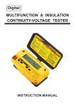
CPS Energy Balancer Installation and Operation Manual Version: 1.0 CHINT POWER SYSTEMS AMERICA CO., LTD. Address: 700 International Parkway, Suite 102 Richardson, Texas Zip Code: 75081 Web: www.chintpower.com/na Email: [email protected] Service Hotline: 855-584-7168 SHANGHAI CHINT POWER SYSTEMS CO., LTD. All rights reserved. Specifications and designs included in this manual are subject to change without notice. CHINT POWER 2013/08-MKT PN: 9.0020.0134B0 Table of Contents Before You Start… ......................................................................................1 IMPORTANT SAFETY INSTRUCTIONS ......................................................2 Chapter 1 Overview ..................................................................................5 1.1 Application of CPS Energy Balancer .............................................5 1.2 Appearance description of CPS Energy Balancer .........................6 Chapter 2 Installation ...............................................................................7 2.1 Basic requirements ........................................................................8 2.2 Mechanical installation ..................................................................9 2.3 Electrical installation ......................................................................12 2.3.1 Set the output voltage ...........................................................14 2.3.2 DC connection ......................................................................15 2.3.3 AC and ground connection ....................................................17 2.3.4 Installation of conduit ............................................................17 2.3.5 Output dry contact connection ..............................................18 2.3.6 Recommended fuses ............................................................18 Chapter 3 Operation .................................................................................19 3.1 Start-up ..........................................................................................19 3.2 Shut-down .....................................................................................19 3.3 Status of indicator lights ................................................................19 3.4 Troubleshooting .............................................................................21 Chapter 4 Technical Data .........................................................................23 Chapter 5 Limited Warranty.....................................................................25 Before You Start… This manual contains important information regarding installation and safe operation of this unit. Be sure to read this manual carefully before using. Thanks for choosing CPS Energy Balancer (referred to in this manual as “The Energy Balancer”). CPS Energy Balancer is a highly reliable product due to its innovative design and perfect quality control. If you encounter any problems during installation or operation of this unit, first check this manual before contacting your local dealer or supplier. Instructions inside this manual will help you solve most installation and operation difficulties. Please keep this manual on hand for quick reference. 1 IMPORTANT SAFETY INSTRUCTIONS (SAVE THESE INSTRUCTIONS) Please read this user manual carefully before undertaking the installation. CPS reserves the right to refuse warranty claims for equipment damage if the user fails to install the equipment as per the instructions in this manual. Warnings and symbols in this document DANGER: DANGER indicates a hazardous situation which, if not avoided, will result in death or serious injury. WARNING: WARNING indicates a hazardous situation which, if not avoided, could result in death or serious injury. CAUTION: CAUTION indicates a hazardous situation which, if not avoided, could result in minor or moderate injury. NOTICE: NOTICE indicates a hazardous situation which, if not avoided, could result in equipment working abnormally or property loss. INSTRUCTION: INSTRUCTION indicates important supplementary information or provides skills or tips that can be used to help you solve a problem or 2 save you time. The meaning of mark on the product EARTH GROUND: This symbol marks the location of grounding terminal, which must be securely connected to the earth through the PE (protective earthing) cable to ensure operational safety. DANGER: Please disconnect the Energy Balancer from DC and AC sides before opening the cover of the device. Make sure hazardous high voltage and energy inside the device has been discharged. Do not operate or maintain the Energy Balancer until at least 5 minutes after disconnecting all sources from DC and AC sides. WARNING: All the installation and cable connections should be performed only by qualified technical personnel. Disconnect the Energy Balancer from both DC and AC sides and make sure it is safely grounded 3 before maintaining and operating the device. NOTICE: CPS Energy Balancer can NOT be applied in the energy storage PV system. NOTICE: Do not install the Energy Balancer under direct sunlight to avoid conversion efficiency de-rating caused by excessively high temperature. CAUTION: Although designed to meet international safety standards, the Energy Balancer can become hot during operation. Do not touch the heat sink or peripheral surfaces during or shortly after operation. 4 Chapter 1 Overview 1.1 Application of CPS Energy Balancer The Potential Induced Degration (PID) phenomenon of crystalline silicon PV modules can directly affect and obviously reduce the output power of PV modules. The Energy Balancer can impose 400V~950V high voltage on the PV modules and protecting earthing (PE) to effectively recover the PID problem. Figure 2-1 Diagram of CPS Energy Balancer connection 5 1.2 Appearance description of CPS Energy Balancer 1 3 2 Figure 2-2 Appearance of CPS Energy Balancer Description of main items of CPS Energy Balancer (see Figure 2-2): 1. LED indicator lights: show the status of CPS Energy Balancer 2. Knockout hole for AC input cable entry 3. Knockout hole for DC output cable entry 6 Chapter 2 Installation Below is the installation instruction of the Energy Balancer. Please read carefully and install the product step-by-step. Check and make sure that the following items are included in the package before installation, as shown in Table 3-1. Table 3-1 Main items No. (1) (2) Item Q’ty CPS EB-2 1 Installation and 1 Operation manual (3) Warranty card 1 (4) Expansion screws 4 (5) Packing list 1 7 Note 2.1 Basic requirements NOTICE: Do not install the Energy Balancer under direct sunlight to avoid conversion efficiency de-rating caused by excessively high temperature. Check and make sure that the ambient temperature of the installation location is -86°F to +140°F / -30°C ~ +60°C; Make sure that the power grid voltage is within normal range; Permission of grid connection has been granted by the local electric power authority; Installation personnel must be qualified electricians or people who have received professional training; Sufficient convection space; Away from flammable and explosive substances. 8 2.2 Mechanical installation (1) Dimensions 150mm(5.90in) 250mm(9.84in) The dimensions of the Energy Balancer are shown in Figure 3-1. 80mm (3.15in) 320mm(12.60in) Figure 3-1 Dimensions of CPS SC20KTL-DO/US-480 (2) Check whether the wall to install the Energy Balancer is solid enough: (a) The Energy Balancer supports vertical installation for cables coming out from the downside; (b) The Energy Balancer supports slanting installation by 15°to 90°; Cable ° -90 15° Cable Cable Figure 3-2 Mounting the Energy Balancer properly 9 (3) Space required for the Energy Balancer mounting on the wall (as shown in Figure 3-3) The Energy Balancer should be mounted vertically. The distances between the inverter and the surrounding objects should meet the following conditions: two sides from the walls ≥100mm (3.94in.); top distance ≥100mm 3.94in. 100mm (3.94in.); bottom distance ≥300mm (11.81in.). 11.81in. 100mm 3.94in. 300mm 100mm 3.94in. Figure 3-3 Inverter mounting dimensions (4) Install the Energy Balancer: (a) Mark the 4 expansion screw holes for mounting the device; 10 DANGER: The natural gas pipe or electric cable may be located behind the mounting wall. The pipe or cable can be damaged when drilling the holes. Please check and make sure the installation place is secure without pipe or cable to avoid the risk of electric shock or explosion. (b) Drill the holes on the mounting wall; Table 3-2 Specifications of drilling holes Diameter 6mm (0.24in.) Length 30mm (1.18in.) (c) Fix the Energy Balancer on the wall with expansion screws; Figure 3-4 Install the Energy Balancer on the wall 11 2.3 Electrical installation The cable connection terminals of the Energy Balancer are shown in Figure 3-5: S30 L N NO P10 NO PV1 PV2 - + - + GND P15 -+ P11 P16 2 3 1 4 [*] [*] P13 Figure 3-5 The cable connection terminals of the Energy Balancer Recommend PositionDescription Torque Tool cable (N.m) 4mm P10 Connector for AC input flat #18~10AWG 1.2 screwdriver Connector for P11 PV1 4mm #18~10AWG voltage detection P13 flat 1.2 screwdriver Terminal for PV output #18~10AWG 12 #2 cross 2 grounding screwdriver Connector for Output dry P15 3mm flat #22~18AWG contact Connector PV2 voltage P16 0.5 screwdriver 4mm flat #18~10AWG detection 1.2 screwdriver Terminal for Protection #2 #18~10AWG grounding 2 screwdriver 13 cross 2.3.1 Set the output voltage The output voltage of the Energy Balancer can be configured by the DIP switch (S30). Each DIP switch in Figure 3-6 corresponds with the output voltage as below: 2 3 4 2 3 4 1 NO [*] 1 [*] NO [] 2 3 4 1 2 3 4 NO [*] NO Figure 3-6 Configuration of the output voltage A 400V output voltage B 600V output voltage C 800V output voltage D 950V output voltage 14 1 [*] DIP Switch S30 √ Note:The default output voltage of the Energy Balancer is set to 400V. Please follow the guidelines when setting the output voltage: (a) It is forbidden to configure the dip switch when the Energy Balancer is energized. Disconnect the device from all electrical connections to avoid the risk of high voltage hazard. (b) Check and make sure the output voltage of the Energy Balancer is lower than the withstand voltage of the Y capacitor on the DC side of the inverter to avoid damaging the inverter. 2.3.2 DC connection (1) Please follow the guidelines to achieve the optimized effect of the Energy Balancer: (a) Make sure the Voc of the PV strings is lower than 1000Vdc under any conditions; (b) One Energy Balancer can only work with one inverter, and the equivalent capacity load of PV strings should be ≤1.2uF. (c) Connect the PV1 cables from the PV strings to the P11 socket of the Energy Balancer and the PV2 cables to the P16 socket. Make sure the polarities of PV cable match the positive and negative marks on the sockets. 15 (d) The ground cable from PV strings should be connected to the P13 PV output grounding terminal. (e) When connecting the inverter, check and make sure the output voltage of the Energy Balancer is lower than the withstand voltage of the Y capacitor on the DC side of the inverter to avoid damaging the inverter. (2) Please choose the corresponding cable connection way according to the MPPT working mode of the inverter. (a) When connecting the inverter that works with one MPPT, please short circuit the PV2+ terminal with the PV2- terminal on the socket of the Energy Balancer, as shown below: Figure 3-7 The cable connection with the inverter working with 1 MPPT 16 (b) When connecting the inverter that works with two MPPTs, please connect the cables, as shown below: Figure 3-7 The cable connection with the inverter working with 2 MPPTs 2.3.3 AC and ground connection Connect the L and N cables to the P10 socket, and connect the ground cable to the grounding terminal of the Energy Balancer. 2.3.4 Installation of conduit Please select the EMT or ENT as the conduit for cable connection. The size of conduit should be 1inch or 1.25inch. If conduits are not used for installation, please make sure the same protection level as follows: (a) The Energy Balancer meets the waterproof and dustproof level. 17 (b) The cables are free from tension. 2.3.5 Output dry contact connection The Energy Balancer has an output dry contact port through which the fault can be reported to the inverter. It is recommended to connect a 5KΩ resistance to the positive terminal of the P15 socket to raise the voltage to 15V, and connect a 15V Gnd cable to the negative terminal of the P15 socket. 2.3.6 Recommended fuses Please disconnect the AC and DC sources before replacing the fuses: Table 3-5 Recommended fuses for Energy Balancer Specification Type Brand AC fuse 500Vac @3.15A 04773.15MXP Littelfuse DC fuse 1000Vdc @3A 3A10F Bussmann 18 Chapter 3 Operation 3.1 Start-up Automatic start-up: When the output voltage of PV strings is lower than 50V, the AC grid is normal, and the environmental termperature is within operating range, the Energy Balancer will start up automatically. 3.2 Shut-down Automatic shut-down: The Energy Balancer will shut down automatically when any one of the following conditions happens: 1. The output voltage of PV strings exceeds 75V; 2. Reverse connection of polarities of PV cables; 3. Over-load or short circuit of DC output; 4. Fault of AC grid; 5. Environmental temperature exceeds normal range; 6. Disconnection of PV voltage sampling cables 3.3 Status of indicator lights The Energy Balancer has 3 working modes. Each mode has a corresponding indicator status, as shown below : 19 Table 5-1 LED Indication LED Description State Meaning Sign Light Energized by AC power Work power supply up indicator light Light No working power off supply Light In charging and resetting Grid connection operation up state indicator light Light Standby or no working off power supply POWER RUN Light Fault occurs up FAULT Fault state indicator light Light No fault or no working off power supply (1) Standby mode, the POWER indicator lights up. In this mode, the Energy Balancer stands by to check whether the start-up conditions are met to start up working normally. 20 (2) Normal operation mode : the POWER and RUN indicators light up. In this mode, the Energy Balancer is in normal operation. (3) Fault mode : the POWER and FAULT indicators light up. In this mode, the Energy Balancer will disconnect the output and enter the fault mode. WARNING: All the installation and wiring connections should be performed only by qualified technical personnel. Disconnect the Energy Balancer from PV strings and the AC grid before maintaining and operating the equipment. 3.4 Troubleshooting The LED indication and fault of the ENERGY BALANCER : LED state Fault Description RUN lights off Reverse The voltage of reverse FAULT lights up connection of the connection is higher than 70V. polarities of PV1 Fault shutdown ; FAULT keeps and PV2 lighting up. 21 Over temperature When the environmental temperature is higher than 60℃ ; FAULT keeps lighting up ; When the environmental temperature is lower than 50℃ ; the power will recover. RUN lights off Over-load or Fault shutdown ; If the over-load FAULT blinks once Short circuit of DC or short circuit persists, the output FAULT will blink once every 90s. Over voltage of Fault shutdown ; If the DC output overvoltage persists, the FAULT will blink once every 90s. Open circuit of Fault shutdown ; If the open PV1 and PV2 circuit persists, the FAULT will voltage sampling blink once every 90s. circuit 22 Chapter 4 Technical Data Model Name CPS EB-2 Input Nominal Input Power 10W Max. Input Power <15W Max. Input Current <300mA Norminal Grid Voltage 208-277Vac Single phase Allowable Grid Voltage 166-318Vac Rated Grid Frequency 50-60Hz Output Max. Output Voltage 1000Vdc Output Voltage Range 400-950Vdc 1 Max. Output Current 2×3mA Max. Output Number 2 System Protection Degree NEMA 4 (IP65) Operating Temperature Range -22°F to +140°F / - 30°C to +60°C Cooling Natural cooling Operating Altitude 13123ft / 4000m Operating Humidity 0-95%, non-condensing Stand-by / Night Consumption <3.5W Display Display LED Mechanical Data Dimensions (WxHxD) 12.6×9.9×3.2 in / 320×250×80 mm 1 CPS Energy Balancer has two channels of PV output. The Max. Output Current is 6mA in total. The two channels may not share the same current because of the difference of PV strings. 23 Weight 4Ibs / 1.8kg 24 Chapter 5 Limited Warranty The warranty policy of this product is specified in the contract; otherwise, the warranty period is 5 years. For service, Chint Power Systems America will provide local support. For Warranty terms, please refer to the CPS America standard warranty policy in place at time of purchase. 25