1
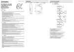
α Series Simple Application Controllers
4.2
What You Should Know Before Starting to Program 4
The Function Block Diagram (FBD) Window
The Function Block Diagram (FBD) window is used to program the α series controller. The
FBD window consists of a large wiring area (lime green by default), a title box and input and
output rectangles vertically along the right and left hand sides, respectively. Programming
components are placed on the wiring area or in the rectangles, and connected by single wires
to construct the program for the α series. The FBD window is also known as FBD Wiring area.
Title bar
Output
Input
Edit program area
The user can perform the following ten operations using FBD window. Refer to Chapter 6 for
more details. The size for edit program area can be changed by the operation of mouse.
1) Place the I/O signals and functions using the Accessories Toolbar.
2) Assign parameters to functions.
3) Wire the various program components together (with the help of Wiring Analyser).
4) Writes the Program logic and I/O device’s information to the α series.
5) Invoke Auto FBD Wizard to begin to program with guidance.
6) Test the program logic with Internal Devices (Input and Output signals placed in the FBD
wiring area).
7)
Simulate and check the programming logic off-line without connecting an
user can:
α
series. The
- force input signals ON/OFF
- change function parameters (timers, counters, analog data, etc.)
- display comments or function values on screen
- Monitor component status via changing wire colors (ex. Red Wire = OFF, Blue Wire =
ON)
8) Read information from an α series and recreate the Program on the FBD window.
9) Monitor an α series on-line.
10) Print the FBD screen and component information shown on the FBD window.
4-3